

Page 1

DVS 605
HDCP-Compliant Scaler
(with Seamless Switching)
User Guide
SCALERS AND SIGNAL PROCESSORS
DVS 605
DVS 605 AD
68-2110-01 Rev. B
05 13
Page 2
Safety Instructions
Safety Instructions • English
WARNING: This symbol, , when used on the product, is intended
to alert the user of the presence of uninsulated dangerous voltage
within the product’s enclosure that may present a risk of electric
shock.
ATTENTION: This symbol, , when used on the product, is intended
to alert the user of important operating and maintenance (servicing)
instructions in the literature provided with the equipment.
For information on safety guidelines, regulatory compliances, EMI/EMF
compatibility, accessibility, and related topics, see the Extron Safety and
Regulatory Compliance Guide, part number 68-290-01, on the Extron
website, www.extron.com.
Instructions de sécurité • Français
avertissement: Ce pictogramme, , lorsqu’il est utilisé sur le
produit, signale à l’utilisateur la présence à l’intérieur du boîtier
du produit d’une tension électrique dangereuse susceptible de
provoquer un choc électrique.
ATTENTION: Ce pictogramme, , lorsqu’il est utilisé sur le produit,
signale à l’utilisateur des instructions d’utilisation ou de maintenance
importantes qui se trouvent dans la documentation fournie avec le
matériel.
Pour en savoir plus sur les règles de sécurité, la conformité à la
réglementation, la compatibilité EMI/EMF, l’accessibilité, et autres sujets
connexes, lisez les informations de sécurité et de conformité Extron,
réf. 68-290-01, sur le site Extron, www.extron.fr.
Sicherheitsanweisungen • Deutsch
WARNUNG: Dieses Symbol auf dem Produkt soll den
Benutzer darauf aufmerksam machen, dass im Inneren des
Gehäuses dieses Produktes gefährliche Spannungen herrschen,
die nicht isoliert sind und die einen elektrischen Schlag
verursachen können.
Chinese Simplified(简体中文)
警告: 产品上的这个标志意在警告用户该产品机壳内有暴露的危险
电 压 ,有 触 电 危 险 。
注意: 产品上的这个标志意在提示用户设备随附的用户手册中有
重要的操作和维护(维修)说明。
关于我们产品的安全指南、遵循的规范、
使用的特性等相关内容,敬请访问 Extron
安全规范指南,产品编号 68-290-01
EMI/EMF 的兼容性、无障碍
网站 www.extron.cn,参见 Extron
。
Chinese Traditional(繁體中文)
警告: 若產品上使用此符號,是為了提醒使用者,產品機殼內存在著
可能會導致觸電之風險的未絕緣危險電壓。
注意 若產品上使用此符號,是為了提醒使用者。
有關安全性指導方針、法規遵守、EMI/EMF 相容性、存取範圍和相關主題的詳細
資訊,請瀏覽 Extron 網站:www.extron.cn,然後參閱《Extron 安全性與法規
遵守手冊》,準則編號 68-290-01。
Japanese
警告: この記 号 が製品上に表示されている場合は、筐体内に絶縁されて
いない高電圧が流れ、感電の危険があることを示しています。
注意: この 記号 が製品上に表示されている場合は、本機の取扱説明書に
記載されている重要な操 作と保守(整備 )の指示についてユーザーの
注意を喚起するものです。
VORSICHT: Dieses Symbol auf dem Produkt soll dem Benutzer in
der im Lieferumfang enthaltenen Dokumentation besonders wichtige
Hinweise zur Bedienung und Wartung (Instandhaltung) geben.
Weitere Informationen über die Sicherheitsrichtlinien, Produkthandhabung,
EMI/EMF-Kompatibilität, Zugänglichkeit und verwandte Themen finden Sie
in den Extron-Richtlinien für Sicherheit und Handhabung (Artikelnummer
68-290-01) auf der Extron-Website, www.extron.de.
Instrucciones de seguridad • Español
ADVERTENCIA: Este símbolo, , cuando se utiliza en el producto,
avisa al usuario de la presencia de voltaje peligroso sin aislar dentro
del producto, lo que puede representar un riesgo de descarga
eléctrica.
ATENCIÓN: Este símbolo, , cuando se utiliza en el producto, avisa
al usuario de la presencia de importantes instrucciones de uso y
mantenimiento recogidas en la documentación proporcionada con
el equipo.
Para obtener información sobre directrices de seguridad, cumplimiento
de normativas, compatibilidad electromagnética, accesibilidad y
temas relacionados, consulte la Guía de cumplimiento de normativas
y seguridad de Extron, referencia 68-290-01, en el sitio Web de Extron,
www.extron.es.
安全上のご注意、法規厳守、EMI/EMF適合性、その他の関連項目に
つ い て は 、エ ク ストロ ン の ウ ェブ サ イト www.extron.jpより
『Extron Safety and Regulatory Compliance Guide 』 (P/N 68-290-01) をご覧くだ さ い 。
Korean
경고: 이 기호 , 가 제품에 사용될 경우, 제품의 인클로저 내에 있는 접지되지
않은 위험한 전류로 인해 사용자가 감전될 위험이 있음을 경고합니다.
주의: 이 기호 , 가 제품에 사용될 경우, 장비와 함께 제공된 책자에 나와
있는 주요 운영 및 유지보수(정비) 지침을 경고합니다.
안전 가이드라인, 규제 준수, EMI/EMF 호환성, 접근성, 그리고 관련
항목에 대한 자세한 내용은 Extron 웹 사이트(www.extron.co.kr)의
Extron 안전 및 규제 준수 안내서, 68-290-01 조항을 참조하십시오.
Page 3

FCC Class A Notice
This equipment has been tested and found to comply with the limits for a Class A digital device,
pursuant to part15 of the FCC rules. The ClassA limits provide reasonable protection against harmful
interference when the equipment is operated in a commercial environment. This equipment generates,
uses, and can radiate radio frequency energy and, if not installed and used in accordance with the
instruction manual, may cause harmful interference to radio communications. Operation of this
equipment in a residential area is likely to cause interference; the user must correct the interference at
his own expense.
NOTE: For more information on safety guidelines, regulatory compliances, EMI/EMF
compatibility, accessibility, and related topics, see the “Extron Safety and Regulatory
Compliance Guide” on the Extron website.
Copyright
© 2013 Extron Electronics. All rights reserved.
Trademarks
All trademarks mentioned in this guide are the properties of their respective owners.
The following registered trademarks
(®)
, registered service marks
(SM)
, and trademarks
(TM)
are the property of
RGBSystems, Inc. or Extron Electronics:
Registered Trademarks
AVTrac, Cable Cubby, CrossPoint, eBUS, EDID Manager, EDID Minder, Extron, Flat Field, GlobalViewer, Hideaway, Inline, IPIntercom, IPLink,
Key Minder, LockIt, MediaLink, PoleVault, PowerCage, PURE3, Quantum, SoundField, SpeedSwitch, System Integrator, TeamWork, TouchLink,
V‑Lock, VersaTools, VN‑Matrix, VoiceLift, WallVault, WindoWall
Registered Service Mark
AAP, AFL (Accu‑Rate Frame Lock), ADSP (Advanced Digital Sync Processing), AIS (Advanced Instruction Set), Auto‑Image, CDRS (Class D
Ripple Suppression), DDSP (Digital Display Sync Processing), DMI (Dynamic Motion Interpolation), DriverConfigurator, DSPConfigurator, DSVP
(Digital Sync Validation Processing), FastBite, FOXBOX, IP Intercom HelpDesk, MAAP, MicroDigital, ProDSP, QS‑FPC (QuickSwitch Front Panel
Controller), Scope‑Trigger, SIS, Simple Instruction Set, Skew‑Free, SpeedMount, SpeedNav, Triple‑Action Switching, XTP, XTP Systems, XTRA,
ZipCaddy, ZipClip
(SM)
: S3 Service Support Solutions
Trademarks
(®)
(™)
Page 4

Conventions Used in this Guide
Notifications
The following notifications are used in this guide:
DANGER: A danger indicates a situation that will result in death or severe injury.
WARNING: A warning indicates a situation that has the potential to result in death or
severe injury.
CAUTION: A caution indicates a situation that may result in minor injury.
ATTENTION: Attention indicates a situation that may damage or destroy the product or
associated equipment.
NOTE: A note draws attention to important information.
TIP: A tip provides a suggestion to make working with the application easier.
Software Commands
Commands are written in the fonts shown here:
^AR Merge Scene,,Op1 scene 1,1 ^B 51 ^W^C
[01] R 0004 00300 00400 00800 00600 [02] 35 [17] [03]
E X! *X1&* X2)* X2#* X2! CE}
NOTE: For commands and examples of computer or device responses mentioned
in this guide, the character “0” is used for the number zero and “O” represents the
capital letter “o.”
Computer responses and directory paths that do not have variables are written in the font
shown here:
Reply from 208.132.180.48: bytes=32 times=2ms TTL=32
C:\Program Files\Extron
Variables are written in slanted form as shown here:
ping xxx.xxx.xxx.xxx —t
SOH R Data STX Command ETB ETX
Selectable items, such as menu names, menu options, buttons, tabs, and field names are
written in the font shown here:
From the File menu, select New.
Click the OK button.
Specifications Availability
Product specifications are available on the Extron website, www.extron.com.
Page 5

Contents
Introduction............................................................ 1
DVS 605 Series Description
Licensed Third‑party Software Used in the DVS
605 ................................................................... 2
Key Features
Video Inputs
Video Outputs
Audio
General ........................................................... 4
Controlling the DVS 605
...................................................... 3
................................................... 3
................................................ 3
.............................................................. 4
................................ 1
..................................... 6
Rear Panel Connections ..................................... 7
Rear Panel Cabling
............................................. 7
Operation .............................................................. 12
Front Panel Overview
Powering Up
The DVS 605 Menu System — Configuration and
Adjustments
Menu Navigation Using Front Panel Controls
Menu Overview ............................................. 14
User Presets
Picture Control
Input Configuration
Output Configuration
Audio Configuration (All Models) ................... 22
Advanced Configuration
View Comm Settings
Exit Menu
Front Panel Lockout (Executive Modes)
Window vs. Image Size Position — An Overview 28
Picture‑in‑picture (PIP) Mode ............................ 29
Front Panel Activation ................................... 29
PIP Presets
Other DVS 605 Operating Features .................. 31
Screen Save ................................................. 31
Power Save
Custom EDID/Custom Output Resolution ..... 31
The OSD Bug
Hardwired IR Port ......................................... 32
Resetting the Unit ............................................. 33
................................................... 13
.................................................... 13
..................................................... 26
........................................ 12
13
................................................. 16
.............................................. 16
....................................... 17
.................................... 18
............................... 23
.................................... 26
............ 27
.................................................. 30
................................................. 31
............................................... 32
SIS Communication and Control .................... 34
Host to Scaler Communications
Scaler‑initiated Messages ............................. 34
Copyright Information ................................... 34
Password Information ................................... 35
Error Responses ........................................... 35
Error Response References
Commands and Responses
Using the Command and Response Tables .. 35
Symbol Definitions ........................................ 36
SIS Command and Response Table ................. 42
SIS Command and Response Table for IP
Control Port ................................................. 56
....................... 34
.......................... 35
............................. 35
Using the Default Web Pages ......................... 61
Accessing the Default Web Pages .................... 61
Turning Off Compatibility Mode ..................... 62
Navigating the Default Web Pages .................... 62
Configuration Pages ......................................... 63
AV Controls Panel ........................................ 63
Input/Output Configuration Page — Input
Configuration Panel ..................................... 65
Input/Output Configuration Page — Output
Configuration Panel ..................................... 67
EDID Minder Page ........................................ 69
Image Settings Page..................................... 71
PIP Settings Page ......................................... 74
Audio Settings Page ..................................... 77
Preset Management Page ............................ 79
Device Settings Page .................................... 80
Hardware Pages ............................................... 83
Unit Information Page ................................... 83
Device Name Page ....................................... 84
Connection Settings Page ............................ 84
Firmware Loader Page .................................. 85
Executive/Power Mode Page ........................ 86
Date and Time Page ..................................... 87
Password Page
............................................ 88
DVS 605 • Contents v
Page 6

Mounting ............................................................... 90
Mounting the DVS 605 ..................................... 90
Tabletop Placement ...................................... 90
UL Guidelines for Rack Mounted Devices .... 90
Rack Mounting ............................................. 91
Furniture Mounting........................................ 91
Warranty................................................................ 92
Contact Information ........................................... 92
DVS 605 • Contents vi
Page 7

Introduction
This manual contains information about the Extron DVS 605 scalers with instructions for
experienced installers on how to install, configure, and operate the equipment.
In this manual the terms “DVS,” “digital video scaler,” and “scaler” are used
interchangeably and refer to any DVS 605 model.
DVS 605 Series Description
The DVS 605 series of digital video scalers is comprised of:
• DVS 605, standard model
• DVS 605 A, with audio switching
• DVS 605 D, with 3G/HD‑SDI output
• DVS 605 AD, with 3G/HD‑SDI output and audio switching
All models are full rack width, and are available with optional 3G/HD‑SDI outputs (DVS
605 D and DVS 605 AD) and balanced/unbalanced audio (DVS 605 A and DVS 605 AD).
All models are high performance video scalers that include three HDMI inputs, two
universal analog video inputs, and simultaneous HDMI and analog high resolution
outputs. The DVS 605 models accept a wide variety of video formats including HDMI with
HDCP, HDTV, RGB, and standard definition video. They feature advanced Extron video
signal processing with 1080i de‑interlacing, Deep Color processing, and true seamless
switching for professional‑quality presentations. The DVS 605 models offer flexible control
options including Ethernet, RS‑232, USB, hardwired IR, and contact closure.
The five inputs of all DVS 605 models accommodate a variety of sources. The analog
inputs can automatically detect and process RGB computer‑video, HDTV, component
video, S‑video, and composite video. The DVS 605 provides the capability to integrate
digital and analog video devices, with HDCP compliance to enable integration of Blu‑
Ray Disc players and cable or satellite HD receivers. Auto‑switching between inputs
streamlines system operation as well as integration with presentation switchers or matrix
switchers.
Output scan rates are available from VGA (640x480) to 1920x1200 resolution, as well as
HDTV at 720p, 1080i, 1080p/60 Hz, and 2k/60 Hz.
NOTE: See the Resolution and Refresh Rates table on page 18 for a complete
list.
The DVS 605 models feature EDID Minder and Key Minder. EDID Minder automatically
manages Extended Digital Identification Data (EDID) communications between the display
device and all the HDMI and VGA computer‑video input sources.
For HDMI signals with protected content, Key Minder authenticates and maintains
continuous HDCP encryption between input and output devices to ensure quick and
reliable switching in professional AV environments.
DVS 605 models with audio switching feature HDMI audio embedding and
de‑embedding. Any input audio signal can be embedded onto the HDMI output.
DVS 605 audio models can also extract embedded HDMI audio to analog and digital
S/PDIF outputs. The DVS 605 AD, with audio switching plus 3G‑SDI/HD‑SDI output, can
embed up to eight channels of audio onto the SDI output.
DVS 605 • Introduction 1
Page 8

Licensed Third-party Software Used in the DVS 605
The DVS 605 uses various licensed third‑party software during operation. To view details
about third‑party packages and associated licensing, click the License Information
button on the Unit Information page of the Default web pages (see the Unit Information
Page on page 82). The DVS605 License Information
dialog box opens.
To view a copy of a listed package license, in the dialog
box, click the link in the License column for the relevant
package. This opens in a separate window a copy of the
package license.
Click Close to close the dialog box.
The table below lists the licensed third‑party software
used by the DVS 605.
NOTE: Licensed third‑party software used by the
DVS 605 is subject to change without notice.
Licensed Third-party Software Used in the DVS 605
Package License Package License
avahi GNU LGPL v2.1
bstrib BSD lighttpd BSD
busybox GNU GPL v2 Linux
bzip2 BSD
cjson MIT
expat BSD luafilesystem MIT
ExtJS4 Sencha Commercial License luasocket MIT
fcgi fcgi
freetype Free Type License mtd GNU GPL v2
gnupg-1.4.7 GNU LGPL v2.1
gpgme GNU LGPL openssh BSD
ifplugd GNU GPL openssl OpenSSL
jpeg libjpeg
libassuan GNU LGPL
libcgicc 3.2.3
libcurl ICS qt
libdaemon
libdnet BSD
libgpg
libcap BSD xinetd Custom
net‑snmp BSD
GNU LGPL v2.1
GNU GPL v2.1
GNU GPL v2.1
libpng libpng license
GNU GPL v2
lua MIT
lua‑cjson MIT
luastruct MIT
ncurses MIT
PAM BSD
pcre BSD
psmisc GNU GPL v2
GNU LGPL v2.1
socat
spawn‑fcgi BSD
sqlite Public Domain
GNU GPL v2
DVS 605 • Introduction 2
Page 9

Key Features
Video Inputs
• Three HDMI and two universal analog video inputs — The two universal 15‑pin
HD inputs automatically detect incoming RGB, HD component video, YUVi, S‑video,
or composite video signals. The DVS 605 allows for seamless switching between
HDMI and analog video sources.
• Auto input format detection — For the universal analog video inputs, the DVS 605
detects the incoming signal format, automatically reconfiguring the scaler to provide
the appropriate decoding and signal processing.
• Auto-switching between inputs — The DVS 605 can automatically switch between
input sources. The unit can be set up to automatically switch to an active input, by
giving priority to the highest active input (51), or to the lowest active input (15).
This allows for simple, automated control of the DVS 605 when a control system is
not in use.
Auto Switch feature detects “active” video inputs by the presence of valid Horizontal
and Vertical sync inputs, and not by the presence of an input cable, or +5 VDC from
a source that is currently not outputting active video. Using simultaneous video input
detection on all inputs, the DVS 605 will switch to the active input depending on the
configured order of precedence (highlow vs. lowhigh).
With auto‑switching, the DVS 605 can accommodate additional inputs when
connected to the outputs of a larger presentation switcher, or can be used for
unmanaged switching, or as an upstream matrix switcher.
Video Outputs
NOTE: When Auto Switch mode is active, PIP mode cannot be enabled. Similarly,
if PIP mode is currently active, Auto Switch mode cannot be enabled.
• True seamless switching — Seamless cut and dissolve transition effects are
available for inputs 1 to 4. Input 5 features glitch‑free switching with a fade through to
black.
• 3G/HD-SDI output — Active only if the current resolution is set to 720p, 1080i,
1080p, or 2k 23.98/24/25 Hz. All video outputs (HDMI, VGA, SDI) share a common
output resolution and display the same content.
• Simultaneous scaled outputs for HDMI, HD-SDI, and analog RGB or HD
component video — HDMI and high resolution analog RGB or component video
outputs are available for driving two displays.
• Selectable output rates — Available output rates include computer video (640x480 )
up to 1920x1200, HDTV rates up to 1080p/60 Hz, and 2048x1080 (2k/60 Hz).
• Picture-in-picture (PIP) — For inputs 1 to 4, the DVS 605 provides unrestricted
two‑window display of standard definition and high resolution digital and analog video
sources. Multiple PIP presets are available, including side‑by‑side windows. The
main and PIP windows can be dynamically sized, positioned, and magnified. In audio
models, audio switching can be set to follow either the main or PIP window.
DVS 605 • Introduction 3
Page 10

Audio
• Audio switching — The DVS 605 A and DVS 605 AD feature audio switching for five
analog stereo balanced or unbalanced inputs.
• Output volume control — DVS 605 audio models provide master volume control.
Fixed and variable line level outputs are available, and each output can be balanced
or unbalanced. Stereo input signals can be output as dual mono. The DVS 605 audio
models also include a S/PDIF digital audio output.
• Audio input gain and attenuation — Gain or attenuation can be adjusted for each
analog audio input to eliminate noticeable differences when switching between
sources.
• Audio breakaway — Provides the capability to break an analog audio signal away
from its corresponding video signal and route to the audio outputs, allowing the
analog audio channels to be operated as a separate switcher.
• Audio switching transitions — A transition technique can be applied during
switches that lowers the audio of the switched‑out source while simultaneously
bringing up the audio of the activated source. The duration of the audio crossfade
matches the duration of the video switching transition.
• Integrated audio delay — The DVS automatically delays all analog and digital audio
inputs to compensate for internal video processing delay. Occasionally additional
audio delay is required to account for other signal processors, scalers, or display
devices in a system. For these situations, the DVS 605 offers an additional 0‑255 ms
static global audio delay that can be set via SIS command or internal web pages to
eliminate audio “lip sync” issues.
• HDMI audio embedding and de-embedding — For DVS 605 models with audio,
analog input audio signals can be embedded onto the HDMI output signal.
The DVS 605 can also extract PCM embedded HDMI audio signals. Encoded
bitstream audio for Dolby® Digital or DTS® Digital Surround a can be passed to the
HDMI and S/PDIF outputs.
General
• HDCP compliance — features include data rates up to 6.75 Gbps, Deep Color, and
HD lossless audio formats.
• HDCP authentication and signal presence confirmation — The DVS 605 provides
real‑time verification via RS‑232 or Ethernet of the HDCP status for each digital video
input and output. This allows for signal and HDCP verification through USB, RS‑232,
or Ethernet, providing feedback to a system operator or helpdesk support staff.
• HDCP visual confirmation — This provides a green signal when encrypted content
is sent to a non‑compliant display, providing immediate visual confirmation that
protected content cannot be viewed on the display.
• Key Minder — This feature continuously verifies HDCP compliance for quick, reliable
switching. It authenticates and maintains continuous HDCP encryption between input
and output devices to ensure quick and reliable switching while enabling simultaneous
distribution of a single source signal to one or more displays.
• Advanced scaling engine — The DVS 605 features a high performance 30‑bit
scaling engine with the ability to scale high resolution computer‑video and HDTV as
well as standard definition video up or down in resolution.
• EDID Minder — This feature automatically manages EDID communication between
connected devices, ensuring all sources power up properly and reliably output
content for display.
DVS 605 • Introduction 4
Page 11

• AFL - Accu-RATE Frame Lock — A patented technology exclusive to Extron that
eliminates image tearing caused by frame rate conversion.
• Image freeze control — A live image can be frozen using control via USB, RS‑232
serial, Ethernet, or IR control.
• Auto-Image setup — When activated, the unit automatically detects the resolution of
the incoming video signal and sets the total pixels, active pixels, and active lines, as
well as the horizontal and vertical starting points.
• Auto Input Memory — When activated, the DVS 605 automatically stores size,
position, and picture settings based on the incoming signal. When the same signal is
detected again, these image settings are automatically recalled from memory.
• On-screen display — The DVS 605 features an on‑screen display that displays
status information of the currently selected input.
• On-screen input labels — An on‑screen text label may be assigned to each input.
The label can be up to 16 characters and input via RS‑232 or Ethernet.
• Power screen saver mode and standby modes — The DVS 605 can be set to
automatically mute video and sync output to the display device when no active input
signal is detected. This allows the projector or flat‑panel display to automatically enter
into standby mode to save energy and enhance lamp or panel life.
• Picture controls — These include brightness, contrast, color, tint, and detail, as
well as horizontal and vertical positioning, and sizing. 16 user memory presets are
available for each input to store all image settings.
• Automatic 3:2 and 2:2 pulldown detection — The DVS 605 offers advanced film
mode processing techniques that help maximize image detail and sharpness for
NTSC, PAL, and HDTV 1080i sources that originated from film.
• Motion adaptive 1080i and SD de-interlacing — The DVS 605 provides high
performance de‑interlacing for 1080i and standard definition signals from sources
including cable or satellite set‑top boxes, delivering optimized image quality through
advanced motion compensation.
• Aspect ratio control — The aspect ratio of the video output can be controlled by
selecting a Fill mode, which provides a full screen output, or a Follow mode, which
preserves the original aspect ratio of the input signal.
• Quad standard video decoding — The DVS 605 uses a digital, 3D adaptive comb
filter to decode NTSC 3.58, NTSC 4.43, PAL, and SECAM signals for integration into
systems worldwide.
• Internal test patterns for calibration and setup — The DVS 605 offers 14 test
patterns; crop pattern, crosshatch, 16 bar grayscale, color bars, alternating pixels,
ramp, white field, 4 x 4 crosshatch, and four aspect ratio patterns – 1.33, 1.78, 1.85,
and 2.35.
• Optional 3G/HD-SDI output with genlock — This output complies with SMPTE
292M and 424M, and ITU digital video standards. Genlock allows synchronization to
an external reference signal for integration into broadcast and production applications.
• Front panel security lockout — This feature locks out all front panel functions
except for input selection; all functions however, are available through USB, RS‑232,
or Ethernet control.
• Hardwired IR connection — The DVS 605 features a rear panel hardwired IR port
for connection to Extron MediaLink Controllers, IP Link Control Processors, or IR
receivers for additional control flexibility.
• Ethernet monitoring and control — The DVS 605 can be controlled and proactively
monitored over a LAN, WAN, or the Internet. An intuitive web interface is included for
setup and control.
DVS 605 • Introduction 5
Page 12

• RS-232 control port — Using serial commands, the DVS 605 can be controlled and
configured via the embedded web pages, or integrated into a control system. Extron
products use the SIS ‑ Simple Instruction Set command protocol, a set of basic ASCII
code commands that allow for quick and easy programming.
• Front panel USB configuration port — Enables easy configuration without having to
access the rear panel.
• Contact closure ports — These can be used for external control of source
switching.
• Rack-mountable — The DVS 605 has a 1U, full rack width metal enclosure.
• LockIt HDMI cable lacing brackets — These brackets are included and are used to
secure HDMI cables to the device.
• Internal universal power supply — The 100‑240 VAC, 50‑60 Hz, international
power supply provides worldwide power compatibility.
Controlling the DVS 605
All DVS 605 Series units can be controlled using one or more of the following methods:
• The front panel controls.
• A computer, a touch screen panel, or any other device that can send and receive
serial communications through the USB, RS‑232 or Ethernet port. The Extron Simple
Instruction Set (SIS) is a set of simple keystroke commands that can be used with any
such devices.
• Embedded web pages provide a web browser‑style interface for controlling the scaler
from a computer over a LAN network.
• Hardwired IR.
• Ethernet control via IP Link, enabling the scaler to be controlled and actively
monitored over a LAN, WAN, or the Internet.
DVS 605 • Introduction 6
Page 13
Rear Panel Connections
This section describes how to connect cables to a DVS 605 scaler.
Rear Panel Cabling
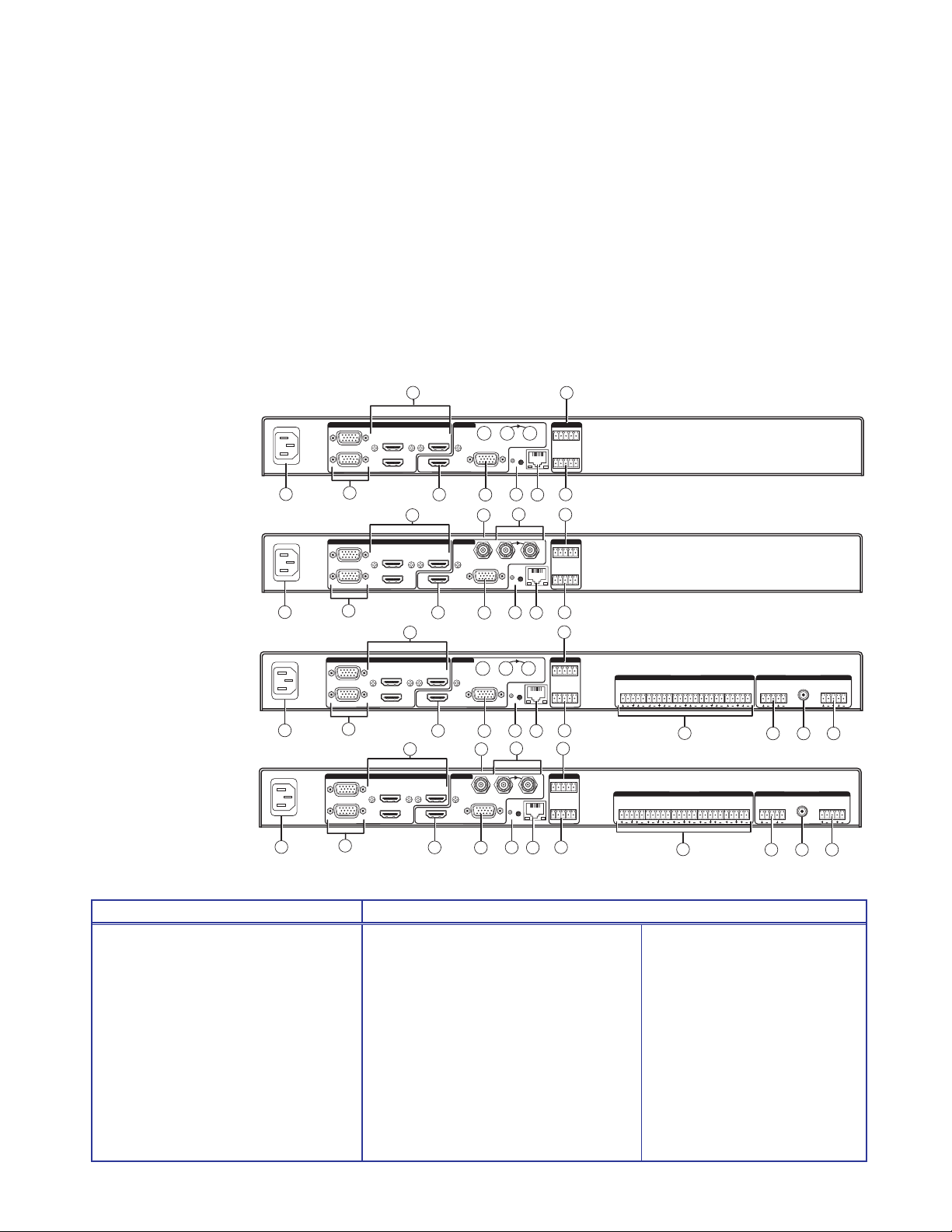
The illustration below shows all the possible rear panel features of the audio (DVS 605 A
and DVS 605 AD) and the non‑audio (DVS 605 and DVS 605 D) models.
DVS 605
1
3
UNIVERSAL
2
1
2
1
2
1
2
UNIVERSAL
UNIVERSAL
UNIVERSAL
2
4
2
3
4
2
3
4
2
3
4
100-240 VAC ~ .7A MAX
50/60Hz
1
DVS 605 D
100-240 VAC ~ .7A MAX
50/60Hz
1
DVS 605 A
100-240 VAC ~ .7A MAX
50/60Hz
1
DVS 605 AD
100-240 VAC ~ .7A MAX
50/60Hz
1
3
INPUT OUTPUTS REMOTE
5
AUX
HDMI
3
INPUT OUTPUTS REMOTE
5
HDMI
3G/HD - SDI
RGB/R-Y, Y, B-Y
HDMI
5
6
7
AUX
3G/HD - SDI
RGB/R-Y, Y, B-Y
HDMI
5
6
3
INPUT OUTPUTS REMOTE
5
AUX
3G/HD - SDI
HDMI
HDMI
5
3
INPUT OUTPUTS REMOTE
5
AUX
HDMI
HDMI
5
RGB/R-Y, Y, B-Y
6
7
3G/HD - SDI
RGB/R-Y, Y, B-Y
6
GENLOCK
GENLOCK
12
GENLOCK
RESET
12
GENLOCK
RESET
12
RESET
12
8
RESET
12345
CONTACT
RS-232 IR
Tx Rx SGG
LAN
13
15
8
1 2345
CONTACT
RS-232 IR
Tx Rx SGG
LAN
14
13
15
12345
CONTACT
RS-232 IR
Tx Rx SGG
LAN
14
13
15
12345
CONTACT
RS-232 IR
Tx Rx SGG
LAN
14
13
15
14
L1R L2R L3R L4R L5R L
AUDIO INPUTS AUDIO OUTPUTS
4
AUDIO INPUTS AUDIO OUTPUTS
L1R L2R L3R L4R L5R L
4
FIXED
R
9 10
FIXED
R
9 10
FIXED
VARIABLE
L
R
S/PDIF
11
FIXED
VARIABLE
L
R
S/PDIF
11
Figure 1. DVS 605 Rear Panel Features — All Models
Power and video input connections Output and control connections
a AC power connector
b Universal analog 15-pin VGA connectors
— inputs 1 and 2
e
HDMI connector
RGB/R-Y,Y, B-Y component 15-pin VGA
f
connector
k Audio out (variable), 5-pole
captive screw connector
(audio models only)
l Reset button and LED
c HDMI connectors — inputs 3-5
(Note: PIP is not available on input 5)
d Audio 5-pole captive screw connectors
— inputs 1- 5 (audio models only)
g 3G/HD-SDI connector (optional)
(SDI models only)
h Genlock connectors — input and loop
(SDI models only)
i Audio out (fixed), 5-pole captive
screw connector (audio models only)
m RJ-45 LAN connector
n RS-232 and IR 5-pole captive
screw connector
o Contact closure 5-pole captive
screw connector (shares a ground
with RS-232)
j RCA audio (S/PDIF) out connector
(audio models only)
DVS 605 • Rear Panel Connections 7
Page 14
a Power input — Connect the standard IEC power cord from a 100 to 240 VAC,
50‑60 Hz power source into this connector. The front panel control and input
selection buttons light in sequence during power‑up.
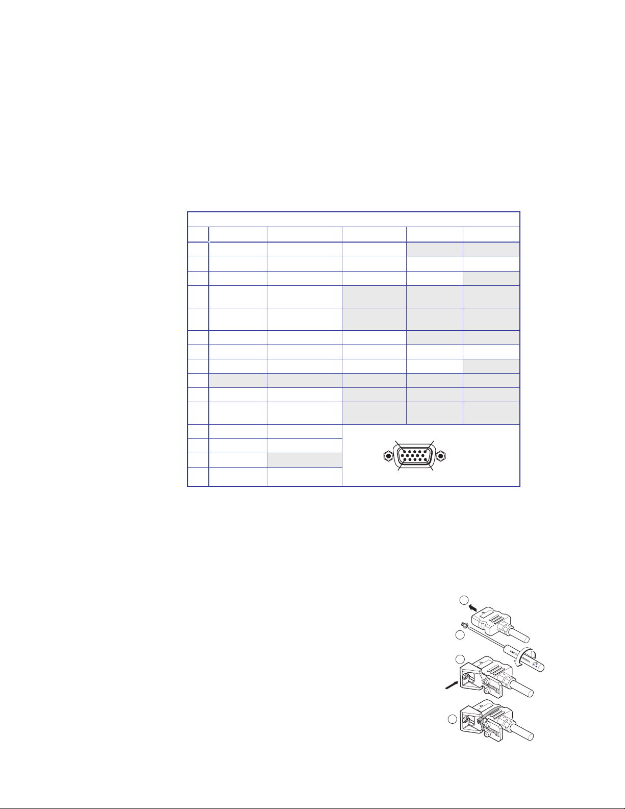
b Inputs 1 and 2 — Connect suitable inputs to these two universal analog input ports
(15‑pin HD [VGA] connectors) for auto‑detection of RGB, HD component video, YUVi,
S‑video, or composite video signals.
These universal analog input ports can be configured to accept RGB (RGBHV, RGBs),
component video (bi‑ or tri‑level), S‑video, or composite video signals. The default
setting is for auto detect. The table below shows the pinouts for each format type on
the 15‑pin HD (VGA) connector. The 15‑pin HD supports EDID emulation.
Pinout Table for 15-pin HD Connector
Pin RGBHV RGBs Component S-video Composite
1 Red Red R-Y
2 Green Green Y Luma Video
3 Blue Blue B-Y Chroma
4 No
Connection
5 No
Connection
6 Red Return Red Return R-Y Return
7 Green Return Green Return Y Return L Return Video Return
8 Blue Return Blue Return B-Y Return C Return
9
10 Ground Ground
11 No
Connection
12 EDID/DDC EDID/DDC
13 H Sync C Sync
14 V Sync
15 EDID/DDC EDID/DDC
No
Connection
No
Connection
No
Connection
15
15
11
c Inputs 3 to 5 — Connect HDMI sources to these three HDMI connectors.
Audio from the HDMI inputs can be de‑embeded from the HDMI source. This allows
the user to choose to select audio either from the HDMI inputs or the analog audio
captive screw inputs. Once an audio source is selected, the unselected source is
disabled. The default selection is 2‑channel digital audio from the HDMI inputs.
Connect up to three digital HDMI and DVD‑D inputs to the HDMI connectors c.
Connect DVI‑D sources using an adapter cable and secure the connectors to the
DVS using the LockIt™ bracket as follows:
1. Plug the HDMI cables into the panel connections.
2. Loosen the side HDMI connection mounting screw
from the panel enough to allow the LockIt
lacing bracket to be placed over it.
3. Place the LockIt lacing bracket onto the screw and
slide it up against the HDMI connector. Tighten the
screw to secure the bracket.
4. Loosely place the included tie wrap around the
HDMI connector and LockIt lacing bracket.
DVS 605 • Rear Panel Connections 8
1
2
3
4
Page 15
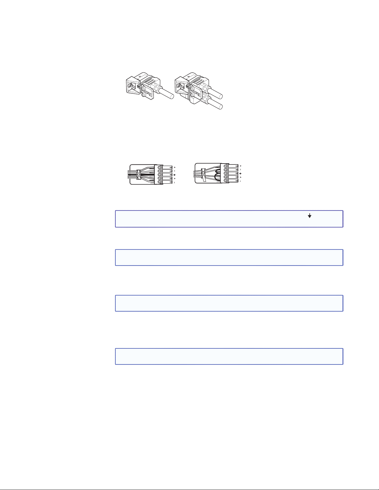
5. While holding the connector securely against the lacing bracket, tighten the tie
wrap, then remove any excess length.
The LockIt bracket can also be used in a stacked formation, as shown below.
Side Mounted
Stacked
Figure 2. LockIt Bracket Mounting Options
d Audio inputs 1-5 (audio models only) — Connect audio sources to these 5‑pole
captive screw connectors. Wire the connector for line level, balanced or unbalanced,
analog stereo as shown below.
Tip
Ring
Sleeves
Tip
Ring
Balanced Stereo Input
LR
Tip
Sleeve
Tip
Sleeve
Unbalanced Stereo Input
LR
Figure 3. Audio Input Connector Wiring
NOTE: Control signal ground pins are labeled “G”. Audio ground pins are as .
The wiring and function are the same, whichever way your product is labeled.
e HDMI output — Connect an HDMI display device to this HDMI connector.
NOTE: All video outputs (HDMI, VGA, SDI) share a common output resolution and display
the same content.
f RGB or HD component (R-Y, Y, B-Y) 15-pin HD video output — Connect an RGB
video display or HD component video display to this HD 15‑pin connector.
NOTE: Simultaneous identical scaled outputs for HDMI and analog RGB or HD
component video are available.
g Optional 3G-SDI/HD-SDI output connector — Connect an SDI (serial digital
interface) display to this female BNC connector for SDI output. This complies with
SMPTE 292M and 424M and ITU video digital standards.
NOTE: 3G/HD‑SDI output is only active if the current resolution is set to 720p, 1080i,
1080p, or 2k 23.98/24/25 hz.
h Genlock connector and loop through (SDI models only) — Connect an external
reference signal for synchronization of the SDI output. The loop through can be used
to synchronize additional devices.
DVS 605 • Rear Panel Connections 9
Page 16
i Audio output (fixed, audio models only) — Connect audio output devices to this
5‑pole, captive screw connector for line level, balanced or unbalanced, analog stereo.
Wire the connectors as shown below.
Tip
Ring
Sleeves
Tip
Ring
Balanced Audio Output
LR
No Ground Here
Tip
Sleeves
Tip
No Ground Here
Unbalanced Audio Output
LR
Do not tin the wires!
Figure 4. Audio Output Connector Wiring
j RCA audio output (S/PDIF, fixed, audio models only) — Plug in an S/PDIF audio
output device into this female RCA connector. This connector outputs digital S/PDIF
audio formats (2‑channel LPCM, Dolby Digital, or DTS).
k Audio output (variable, audio models only) — Connect audio output devices to this
5‑pole, captive screw connector for line level, balanced or unbalanced, analog stereo.
Wire the connectors as shown below.
Tip
Ring
Sleeves
Tip
Ring
Balanced Audio Output
LR
No Ground Here
Tip
Sleeves
Tip
No Ground Here
Unbalanced Audio Output
LR
Do not tin the wires!
Figure 5. Audio Output Connector Wiring
l Reset button and LED — Using an Extron Tweeker, pointed stylus, or ballpoint pen,
press this recessed button for manual resets. The unit has four modes of reset (see
“Resetting the Unit” on page 33 for additional information). The green LED flashes
to show the reset mode indications and that power is on.
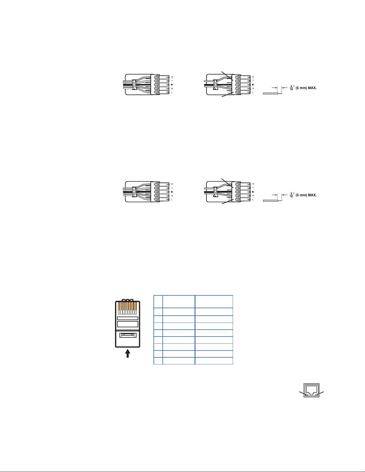
m LAN connector — Plug an RJ‑45 jack into this socket to connect the unit to a
computer network. Use a patch cable to connect to a switch, hub, or router.
Wire the connector as shown below.
Link LED — The green LED lights to indicate a good LAN
Pins:
12345678
Pin
Insert Twisted
Pair Wires
T568A T568B
Wire color
1
White-green
2
Green
3
White-orange
4
Blue
5
White-blue
6
Orange
7
White-brown
8
Brown
Wire color
White-orange
Orange
White-green
Blue
White-blue
Green
White-brown
Brown
RJ-45 Connector
Figure 6. RJ-45 LAN Connector Wiring
LAN Activity LED — A blinking yellow LED indicates LAN activity.
connection.
Activity
Link
LAN
DVS 605 • Rear Panel Connections 10
Page 17

n RS-232/IR port — For serial RS‑232 control, connect a host computer or control
system to the 5‑pole captive screw connector. This port is also a hard wired IR control
for use with an external IR controller.
The default RS‑232 protocol is 9600 baud, 1 stop bit, no parity, 8 data bits, no flow
control.
By default the IR port is disabled. When enbled, the IR port accepts 38 kHz to 1 MHz,
modulated signals at TTL level (0‑5 V)
o Remote contact closure port — For remote input selection of any of the five
inputs, connect a suitable contact closure control device to this 5‑pole captive screw
connector. The contact closure port and the RS‑232 port share a common ground.
DVS 605 • Rear Panel Connections 11
Page 18
Operation
This section of the manual discusses the operation of a DVS 605 device.
Topics covered include:
• Front Panel Overview
• Powering Up
• The DVS 605 Menu System — Configuration and Adjustments
• Front Panel Lockout (Executive Modes)
• Window vs. Image Size Position — An Overview
• Picture-in-Picture (PIP) Mode
• Other DVS 605 Operating Features
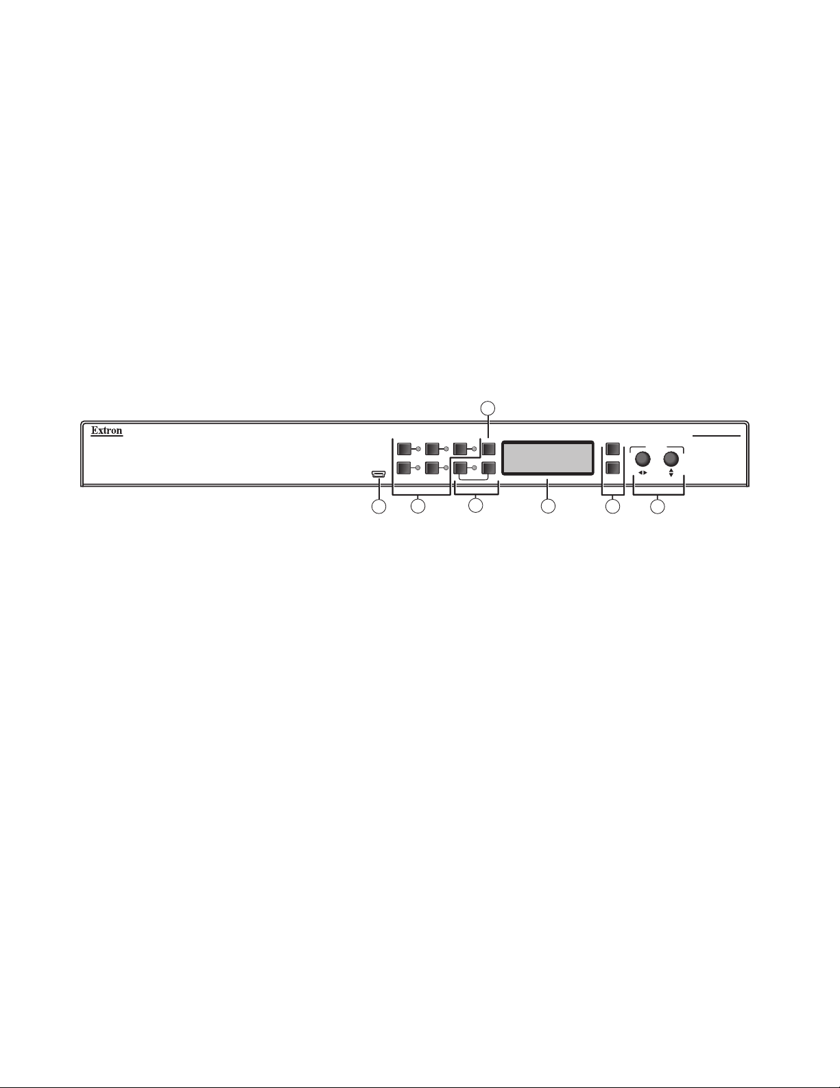
Front Panel Overview
CONFIG
1 2 3
4 5 PIP
AUTO
SWAP
3
DVS 605
DIGITAL VIDEO SCALER
EXTRON
DVS 605
MENU
ADJUST
NEXT
2
1
4
5
6
7
Figure 7. DVS 605 Front Panel Features
a Mini USB configuration port — Connect a control system or computer to this front
panel mini USB port for device configuration, control, and firmware upgrades.
b Input selection buttons and LEDs (1-5) —
Input LEDs — The LED of the selected input lights when the button is pressed. A
blinking LED indicates an audio breakaway input (audio models only).
Inputs 1 and 2 (universal input buttons) — Inputs 1 and 2 select Auto detect, RGB
scaled (RGBHV, RGBS, RGsB), Auto-YUV, RGBcvS, S-video, and composite video inputs.
Inputs 3, 4, and 5 (HDMI/DVI buttons) — Inputs 3, 4, and 5 select HDMI/DVI inputs
c Auto-Image button — Use this to start an Auto-Image function which automatically
sizes and centers an input signal.
d PIP (Picture-In-Picture) button and Swap image button — The PIP button enables
or disables the PIP mode. The Swap button allows the user to swap the two current
inputs displayed in the main and PIP windows.
e LCD display — Displays configuration menus and status information. See “The DVS
605 Menu System — Configuration and Adjustments” section on page 13 for
details.
f Menu navigation buttons (Menu and Next) —
Menu — Use this button to enter and move through the main menu system.
Next — Use this button to step through the submenus of the scaler menu system.
See the “The DVS 605 Menu System — Configuration and Adjustments” section
on the next page for details.
g Adjustment knobs (horizontal [and vertical {) — Using the menu system, rotate
either of these two knobs to scroll through the menu and to make any adjustments.
DVS 605 • Operation 12
Page 19
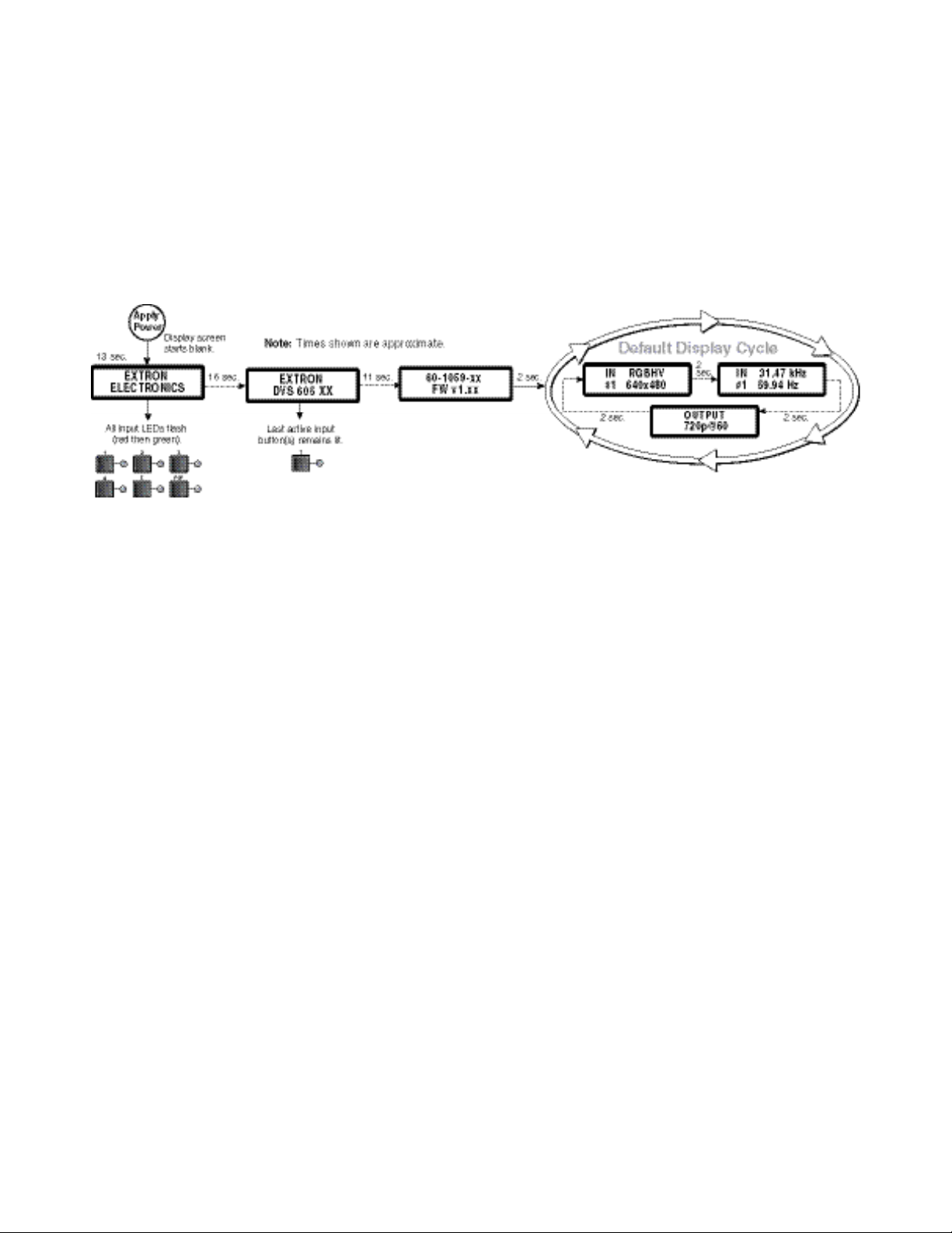
Powering Up
Default Display Cycle
When applying power to the DVS 605, the unit undergoes a start‑up self testing sequence
(see image below) and then the LCD displays the default display cycle.
When in use but not in any menu mode, the LCD screen defaults to cycling through the
input/output configuration currently installed. The displayed content may vary, depending
on the input video signal type. See figure 8 for a typical default display cycle.
Figure 8. Typical Default Display Cycle
The default display cycle shows the scaler output rate and refresh rates for the currently
selected input.
The DVS 605 Menu System — Configuration and Adjustments
Scaler configuration and adjustments can be performed by using the embedded web
pages (see “Using Default Web Pages” starting on page 60 ), the Extron Simple
Instruction Set (SIS) of commands (see “SIS Communication and Control” starting on
page 34), or by using the front panel controls and the menus displayed on the DVS unit’s
Menu Navigation Using Front Panel Controls
LCD screen. These menus are used primarily when the scaler is first set up.
Menu button — Press the Menu button to activate menus and scroll through the eight
main menus.
Next button — Press the Next button to move between the submenus of a selected
main menu item.
Adjust ([,{) knobs — In configuration mode, rotate the Adjust horizontal ([) knob
and Adjust vertical ({) knob to scroll through submenu options and to make adjustment
selections. See the flowcharts in this chapter for explanations on knob adjustments.
DVS 605 • Operation 13
Page 20
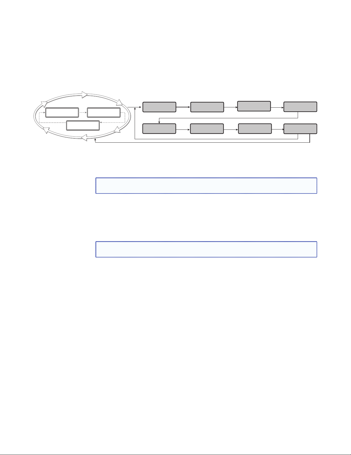
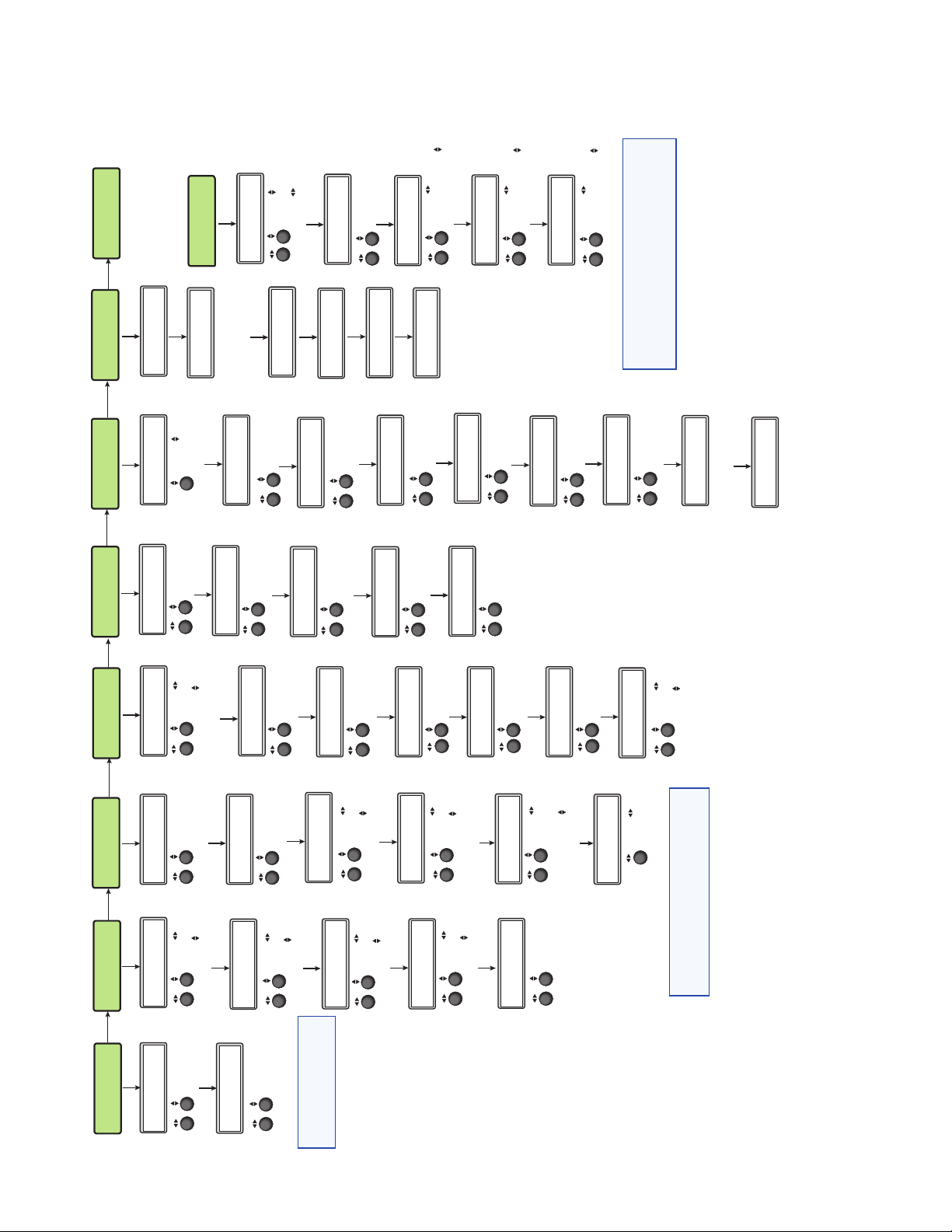
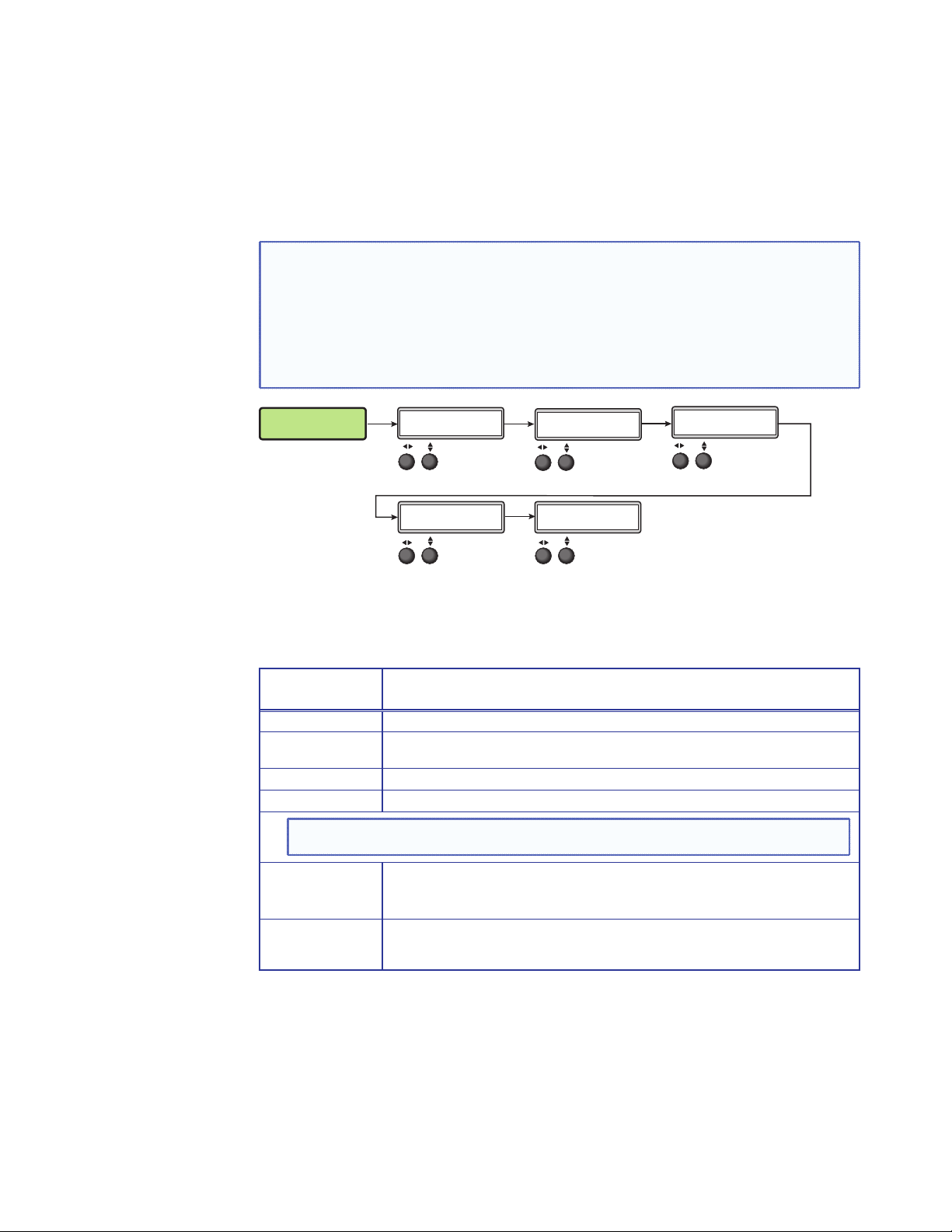
Menu Overview
2 sec.
2
.
640x480
z
z
OUTPU
0
2 sec.
After start‑up, and when no adjustments are actively being made, the “default cycle”
appears on the LCD. The screens cycle between the screen that shows the number and
video format of the active input and the current output resolution.
Pressing the Menu button once brings up the first of eight main (top level) menus, as
shown below. Each successive press of the Menu button goes to the next main menu.
Default Display Cycle
#1
RGBHV
sec
720p@6
IN 31.47 kH
#1 59.94 H
T
Menu
Next
Menu
USER
PRESETS
AUDIO
CONFIG
Menu
Menu
PICTURE
CONTROL
ADVANCED
CONFIG
Menu
Menu
INPUT
CONFIG
VIEW COMM
SETTINGS
Menu
Menu
Menu
Menu
OUTPUT
CONFIG
EXIT MENU?
PRESS NEXT
Next
Figure 9. Top Level Menus
A fourth default cycle menu appears only when genlock is enabled. See “Genlock/AFL
Mode”on page 20) for details.
NOTE: From any menu or submenu, after 20 seconds of inactivity the DVS will save
all adjustment settings and time‑out to the default cycle.
The flowchart shown on page 15 provides an overview of the complete menu system,
with configuration submenus and the options for each setting. In the flow charts the use
of “x”, (for example in (x) or Inx) indicates an input number.
Use the Menu button to scroll between top level menus and press Next to enter the
submenus.
NOTE: If no signal is present on the currently selected input, NO SIGNAL appears in
place of the input type. For example, INPUT 4 NO SIGNAL.
Details of each of the menus are on subsequent pages after the main flow chart.
DVS 605 • Operation 14
Page 21
EXIT MENU?
PRESS NEXT
Menu
Next
SETTINGS
EDIT COMM
“Hidden” Menu *
Rotate to select
RS-232 mode.
Rotate to change
baud rate.
SERIAL PORT
9600 RS232
Next
<ON>
DHCP MODE
Next
Rotate either to turn
DHCP mode on or off.
I 192.168
P 254.254
Next
Rotate to select
octet field. Rotate
to change IP address.
S 255.255
Next
Rotate to select
octet field. Rotate
to change Subnet address.
M 000.000
Rotate to select
octet field. Rotate
to change Gateway address.
G 192.168
W 000.000
Next
SETTINGS
VIEW COMM
SERIAL PORT
Next
9600 RS232
Next
MAC ADRESS
005A6078CEC
This is set at the factory
and cannot be changed
in “Edit Comm Settings”
menu.
Next
On
DHCP MODE
I 192.168
Next
P 254.254
IP address
Next
S 255.255
M 000.000
G 192.168
W 000.000
Subnet mask
Gateway address
*NOTE: To activate the hidden menu “Edit Comms”,
press and hold input 5 and Next buttons
simultaneously for three seconds.
To exit the Edit Comms menu press Menu.
Menu
Next
CONFIG
ADVANCED
AUTO IMAGE
Rotate to turn
Auto Image mode
Input #x OFF
Next
on or off.
Next
Rotate either to select
aspect ratio mode.
IN#x FILL
ASPECT RATIO
Next
Rotate either to turn
auto memory on
or off for selected input.
IN#x ON
AUTO MEMORY
OVERSCAN
Next
Rotate either to set
the overscan mode.
S-VIDEO 5.0%
SWITCH TYPE
Next
Rotate either to
change switch type.
DISSOLVE
Next
Rotate either to
change test pattern.
COLOR BARS
TEST PATTERN
Next
Rotate either to
change OSD
duration.
125 SEC
OSD DURATION
Next
96 F 35 C
TEMPERATURE
Indicates internal temperature
FACT. RESET
(not adjustable).
HOLD AUTO
Press and hold Auto button
to reset unit to factory settings.
Menu
AUDIO
CONFIG
Next
Rotate either to
set volume level.
-30dB
VOLUME
Next
Rotate either to
turn audio mute on
<OFF> ON
AUDIO MUTE
or off.
Next
0 dB
INx GAIN/ATT
Next
Rotate either to
set gain and
attenuation level.
DIGITAL
INx FORMAT
Next
Rotate either to
select input
audio format.
Rotate either to
select audio
output format.
STEREO
AUDIO OUTPUT
Menu
Next
CONFIG
OUTPUT
Rotate to select
1080p@60
RESOLUTION
Next
resolution.
Rotate to select
refresh rate
RGBHV
VGA FORMAT
Next
Rotate either to
select the VGA
format.
Rotate either to
SYNC
H- V-
Next
set sync values.
HDMI FORMAT
Rotate either to
AUTO
Next
set HDMI format.
HDCP NOTE
OFF <ON>
Next
Rotate either to
turn HDCP note
on or off.
GENLOCK/AFL
Rotate either to
set genlock mode.
OFF
Next
110 75
H OFFSET V
Rotate to adjust
horizontal offset.
Rotate to adjust
vertical offset.
Menu
Next
INPUT
CONFIG
Menu
Next
PICTURE
CONTROL
Menu
Next
USER
PRESETS
Rotate either to
select input
signal type.
RGB
INPUT #x
Rotate to adjust
horizontal position.
Rotate to adjust
+00000+00000
(x)H POS V
Rotate either to
select a preset to
recall settings.
<N/A>
INx RECALL
Next
OFF
(x)FILM MODE
Next
vertical position.
00000 00000
(x)H SIZE V
Next
<02>
INx SAVE
Next
Rotate either to
turn film mode
off or to Auto.
Rotate to adjust
horizontal size.
Rotate to adjust
vertical size.
Rotate either
to select a preset
to save current
settings to.
Next
Rotate to adjust
horizontal start.
Rotate to adjust
vertical start.
128 128
(x)H START V
Next
Rotate to adjust
064* *064
(x)BRIT CONT
NOTE: Where used in this
flow chart “x” indicates
the input number.
(x)H ACT V
Next
brightness.
Rotate to adjust
contrast (* = default).
Rotate to adjust
horizontal active pixels.
Rotate to adjust
vertical active pixels
(* = default).
1024* *0768
Rotate to adjust
color.
Rotate to adjust
tint (* = default).
064* *064
(x)COL TINT
Next
Rotate to adjust
1344* 01
(x)TPIX PHAS
Next
Rotate either to
DETAIL
*064
(x)
total pixels
(* = default).
Rotate to adjust
phase.
set detail level
(* = default).
Next
INx EDID
1600x1200@60
Rotate to set an
EDID value for the
active input.
NOTE: The Input Configuration submenus are
input specific and some menus may not
be available depending on the input type.
DVS 605 • Operation 15
Figure 10. Main Menu
Page 22
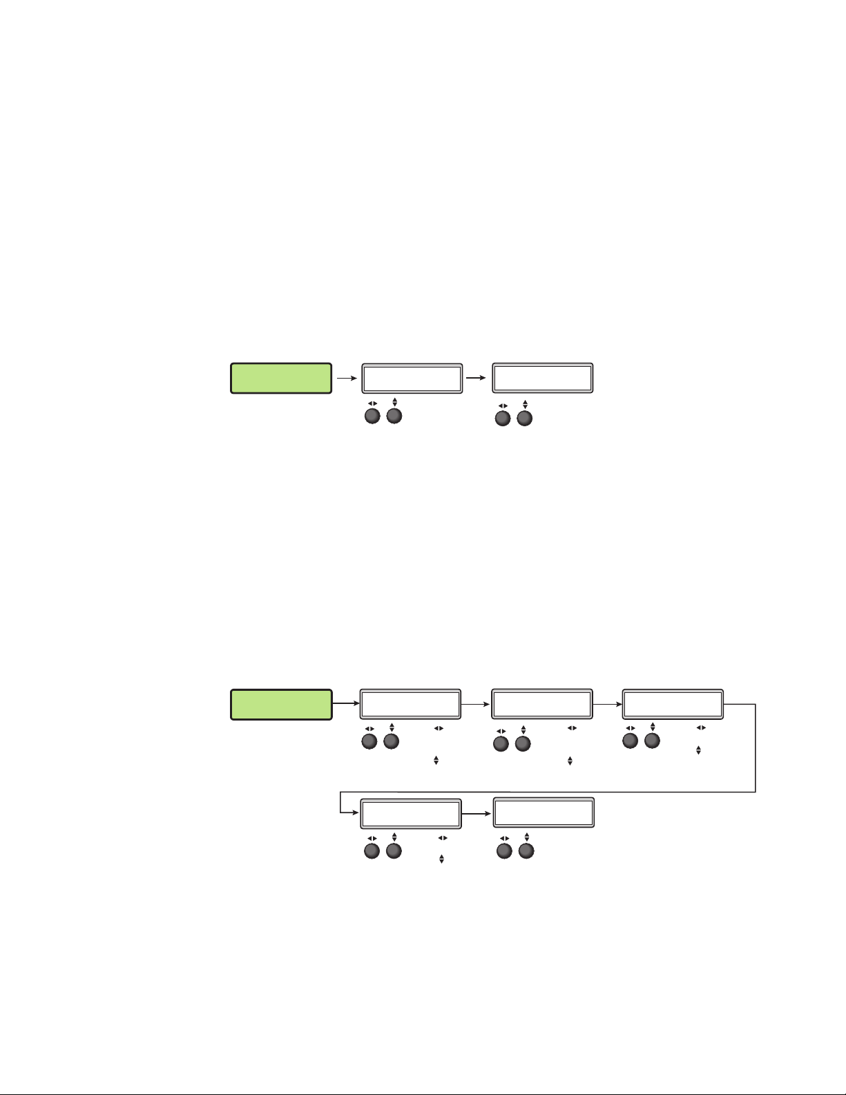
User Presets
To return to the default cycle from within any menu, press the Menu button repeatedly
until the Exit menu appears, then press the Next button. Alternatively, allow the DVS 605
to time‑out (after 20 seconds).
Submenus are accessed from a main menu by pressing the Next button. When within a
submenu, press the Menu button to go out of the submenu and back to the active main
menu.
This menu alows the user save or recall up to 16 presets for the selected input, shown as
INx on the LCD screen.
To use this menu press Next to get the relevant submenu, Recall or Save.
When within the submenu use the Adjust knobs to select the preset to save or recall.
Press Menu to exit the submenu.
USER
PRESETS
Next
INx RECALL
<N/A>
Rotate either to
select a preset to
recall settings.
Next
INx SAVE
<02>
Rotate either
to select a preset
to save current
settings to.
Figure 11. User Preset Menu
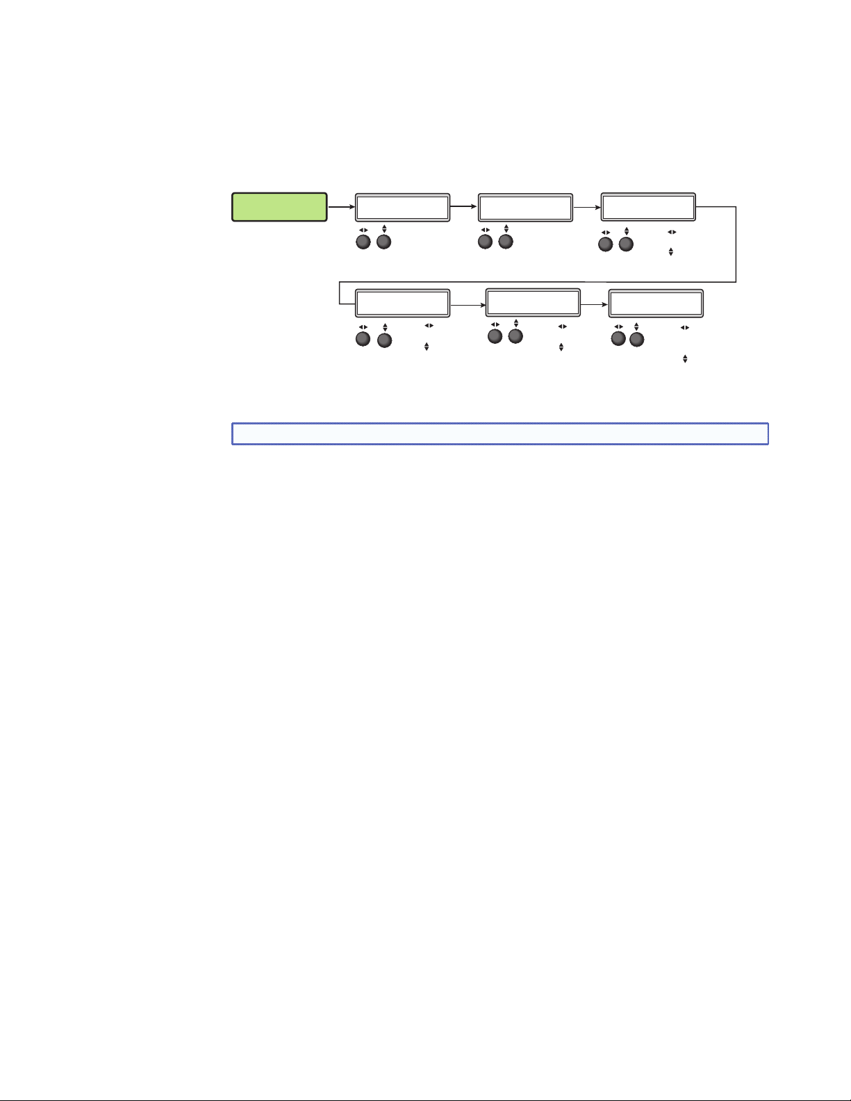
Picture Control
This menu allows the user to adjust various picture control settings such as horizontal and
vertical window positioning, horizontal and vertical window size, brightness and contrast,
color and tint, and detail settings for the selected input. The selected input is shown as (x)
on the LCD screen.
To use this menu press Next to get the relevant submenu.
When within the submenu use the adjust knobs to select and then adjust the values as
desired.
Press Menu to exit the submenu.
PICTURE
CONTROL
Next
Next Next
(x)H POS V
+00000+00000
Rotate to adjust
window horizontal
position.
Rotate to adjust
window vertical
position.
(x)COL TINT
064* *064
Rotate to adjust
color.
Rotate to adjust
tint (* = default).
Figure 12. Picture Control Menu
(x)H SIZE V
00000 00000
Rotate to adjust
window horizontal
size.
Rotate to adjust
window vertical size.
(x)
DETAIL
*064
Rotate either to
set detail level
(* = default).
NextNext
(x)BRIT CONT
064* *064
Next
Rotate to adjust
brightness.
Rotate to adjust
contrast (* = default).
DVS 605 • Operation 16
Page 23
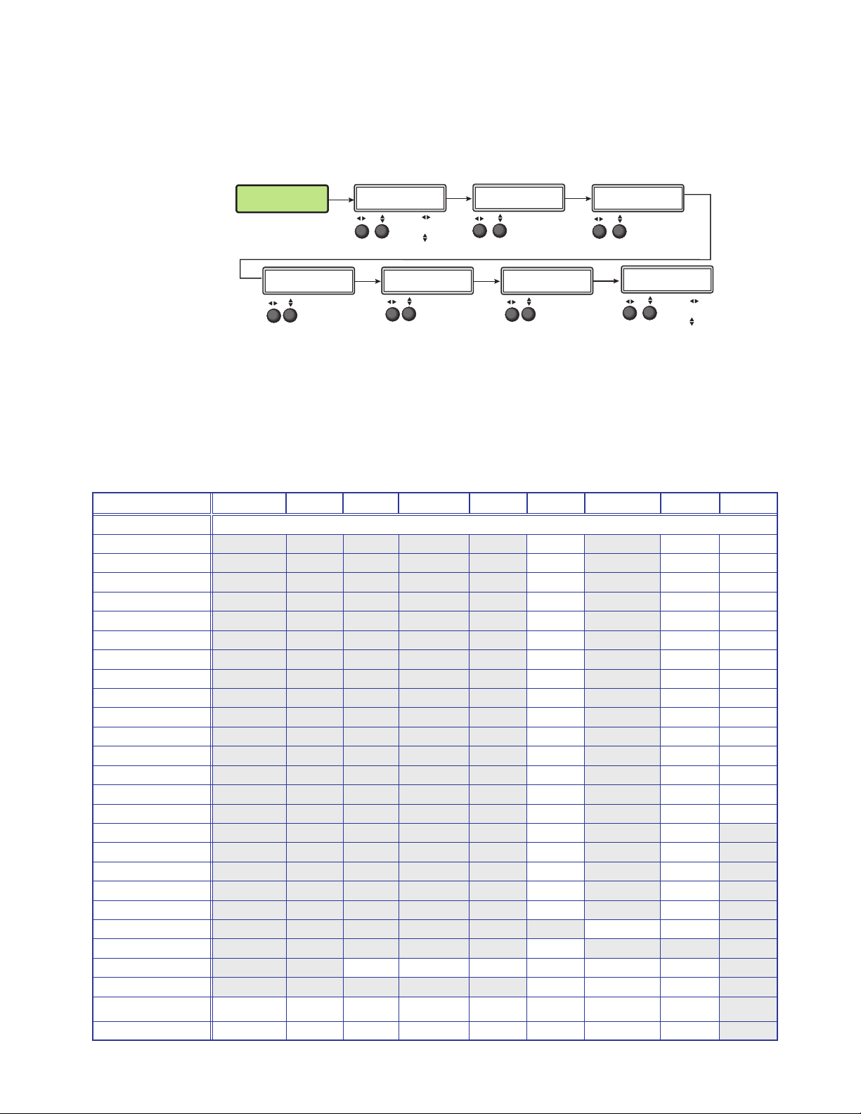
Input Configuration
This menu allows the user to adjust various input configuration settings such as video
signal type, film mode, horizontal and vertical start position, horizontal and vertical active
pixels, total pixel number, phase, and EDID settings for the selected input. The selected
input is shown as (x) on the LCD screen images.
INPUT
CONFIG
Next
INPUT #x
RGB
Rotate either to
select input
signal type.
Next
(x)FILM MODE
OFF
Rotate either to
turn film mode
off or to Auto.
Next
(x)H START V
027 029
Next
Rotate to adjust
horizontal start position.
Rotate to adjust
vertical start position.
Next
(x)H ACT V
1024* *0768
Rotate to adjust
horizontal active pixels.
Rotate to adjust
vertical active pixels
(* = default).
Next
(x)TPIX PHAS
1344* 01
Rotate to adjust
total pixels.
Rotate to adjust
phase (* = default).
Next
INx EDID
1600x1200@60
Rotate to set
EDID resolution for
the active input.
Rotate to set
refresh rate.
Figure 13. Input Configuration Menu
NOTE: Only inputs 1 and 2 offer selectable video types.
Input video types
Rotate either the Adjust horizontal ([) or Adjust vertical ({) knob while in any of the Input
submenus to select the appropriate video format.
Input 1
Input 1 is a universal analog input for RGB scaled, Auto YUV, RGBcvS, S‑video and
composite video.
When input 1 is set to YUV Auto, the scaler detects if YUVi or YUVp/HDTV is applied and
sets the input accordingly.
It can also be set to autodetect the incoming input signal type. This is the default setting.
Input 2
Input 2 is a universal analog input for RGB scaled, Auto YUV, RGBcvS, S‑video and
composite video.
When input 2 is set to YUV Auto, the scaler detects if YUVi or YUVp/HDTV is applied and
sets the input accordingly.
It can also be set to autodetect the incoming input signal type. This is the default setting.
Inputs 3-5
Input 3 through 5 are digital inputs for HDMI or DVI input signals.
DVS 605 • Operation 17
Page 24
Output Configuration
The output configuration menu allows selection of output resolution and refresh rates,
analog output types (RGBHV, RGBS, RGsB and Y, B‑Y, R‑Y), sync polarity, HDMI format,
HDCP notification display, genlock setting, and offset values.
OUTPUT
CONFIG
Next
RESOLUTION
1365x1024@60
Rotate to select
a resolution.
Rotate to select
a refresh rate.
VGA FORMAT
RGBHV
Rotate either to
select VGA
format.
NextNext
SYNC
H- V-
Rotate either to
set sync values.
Next
HDMI FORMAT
AUTO
Rotate either to
set HDMI format.
Next
HDCP NOTE
OFF <ON>
Rotate either to
tun HDCP note
on or off.
Next
GENLOCK/AFL
OFF
Rotate either to
set genlock mode.
Next
H OFFSET V
110 75
Rotate to adjust
horizontal offset.
Rotate to adjust
vertical offset.
Figure 14. Output Configuration Menu
Resolutions and Refresh Rates
Rotate the horizontal ([) knob to select a resolution, and the vertical ({) knob for refresh
rates. The default resolution and rate is 720p/60 Hz.
There are also 5 custom, user‑defined/captured rates available (C1 ‑ C5). When no rate is
captured or uploaded to any of the 5 custom memory slots, they default to 720p/60 Hz.
Resolution 23.98 Hz 24 Hz 25 Hz 29.97 Hz 30 Hz 50 Hz 59.94 Hz 60 Hz 75 Hz
Custom 1 through 5 For captured or uploaded EDID tables
640 x 480 X X X
800 x 600 X X X
852 x 480 X X X
1024 x 768 X X X
1024 x 852 X X X
1024 x 1024 X X X
1280 x 768 X X X
1280 x 800 X X X
1280 x 1024 X X X
1360 x 765 X X X
1360 x 768 X X X
1365 x 768 X X X
1366 x 768 X X X
1365 x 1024 X X X
1440 x 900 X X X
1400 x1050 X X
1600 x 900 X X
1680 x 1050 X X
1600 x 1200 X X
1920x1200 X X
480p X X
576p X
720p X X X X X X
1080i X X X
1080p X X X X X X X X
2k X X X X X X X X
DVS 605 • Operation 18
Page 25

When a new custom rate has been captured or uploaded, the on‑screen display (OSD)
dynamically updates with the new rate for that custom slot. For example if a custom 480p
EDID is uploaded to slot C1, the LCD would read “C1: 720x480”. These five custom slots
are shared between custom output resolutions (based on preferred timings 1 block) and
custom EDID tables, which can be assigned to any DVS input.
Analog Output Format
Using either of the Adjust knobs ([ {), select the output video format required by the
display: RGBHV (default), RGBS, RGsB, YUV bi‑level, and YUV tri‑level.
Sync Polarity
Some display devices may require a particular combination of horizontal (H) and vertical
(V) sync signal polarities. Select the appropriate combination of positive or negative H and
V sync by rotating either the Adjust horizontal ([) or the Adjust vertical ({) knob.
NOTE: If the output format was specified as RGsB or YUV, or RGBS, this submenu
will not be displayed because this menu is only applicable for RGBHV.
HDMI Format
Using either of the Adjust knobs ([ {), select the HDMI format as follows:
• Auto — (based on sink EDID), default
• DVI RGB 444
• HDMI RGB 444 FULL (0‑255, audio, InfoFrames)
• HDMI YUV 444 FULL (0‑255, audio, InfoFrames)
• HDMI YUV 444 LIMT (16‑235, audio, InfoFrames)
• HDMI YUV 422 FULL (0‑255, audio, InfoFrames)
• HDMI YUV 422 LIMT (16‑235, audio, InfoFrames)
HDCP Notification
The HDCP Notification provides a means of determining if HDCP content restrictions are
preventing a video signal from passing. The DVS 605 has the ability to notify the user that
they are currently trying to view HDCP protected content through a non‑HDCP compliant
output port (15‑pin HD or 3G/HD‑SDI) or a non‑HDCP compliant HDMI/DVI display. The
options presented to the user during this scenario are the ability to show a green screen
with a moving “OSD bug” (see page 32) reading “HDCP CONTENT,” or to disable this
message, and instead output muted (black) video on non‑HDCP compliant displays.
The HDCP Notification setting can be adjusted via the front panel menu by using either
of the Adjust knobs ([ {), to turn HDCP notification on or off.
HDCP CONTENT
Figure 15. Green HDCP Notification Screen
It can also be adjusted via the internal web pages or SIS commands.
DVS 605 • Operation 19
Page 26

HDCP Status: Inputs & Outputs
Through a series of SIS commands (see “SIS Communication and Control” starting on
page 34) the DVS 605 has the ability to report HDCP status of the HDMI input signals as
well as connected HDMI sink devices. When the unit is queried, it reports feedback on the
specified input (source) or output (sink) as follows:
• There is no sink or source attached.
• The connected sink supports HDCP, or the connected source is currently providing a
HDCP encrypted signal.
• The connected sink does not support HDCP, or the connected source is currently
providing an unencrypted signal.
HDCP status of the current input can be viewed on the OSD bug. If the input is encrypted
the OSD bug displays an HDCP padlock symbol. The HDCP status of the currently
selected input, and the capabilities of the connected HDMI sink device, can also be
viewed on the AV Controls bar within the internal web pages of the unit.
HDCP Authorized
The HDCP Authorized function allows the DVS 605 HDMI inputs to be able to report
as an HDCP authorized sink or a non‑HDCP authorized sink device to a source. This is
especially useful for sources that will encrypt their output even if the source material does
not require HDCP encryption, which would then prevent content from being displayed on
non‑HDCP compliant displays.
For example, if the user wanted to show a non‑HDCP protected presentation from a PC
using the HDMI output of the PC, there is a chance that the PC will encrypt the HDMI,
because it can see that the DVS 605 HDMI input supports HDCP authorization. If the user
were only going to use the HDMI output of the DVS 605 to a display (sink) that supported
HDCP, there would be no issue; however, if the user wanted to use the DVS 605 analog
15‑pin HD output to an analog sink (display), the green HDCP notification screen would
be displayed, due to the source unnecessarily enabling encryption on its HDMI output.
By disabling HDCP authorization on one of the DVS 605 HDMI inputs, the PC with non‑
HDCP protected content will determine that the signal path does not support HDCP, and
therefore will not encrypt its output. With HDCP authorization disabled on the DVS 605’s
input, the user will be able to view their non‑HDCP protected content from any video
output of the DVS 605. With HDCP authorized disabled on an input, if HDCP protected
content is selected on the source, the source will either simply mute its video output to
black, or display a warning message to the user.
Genlock/AFL Modes
The DVS 605 has the ability to lock the output vertical refresh rate to the selected input
signal vertical refresh rate (AFL), or to an applied SDI Genlock signal (SDI models only).
The 3 available modes for genlock are:
• Off — A free running pixel clock is generated internally by the DVS 605.
• Input AFL — This mode locks the output vertical refresh rate to the vertical refresh
rate of the currently selected input using Extron Accu‑Rate Frame Lock technology to
ensure no frames of the input are repeated or dropped due to frame rate conversion.
This mode will result in glitches / interruptions in output sync when a new DVS 605
input is selected, or when a new signal has been routed to the DVS 605 selected
input, as the DVS 605 locks to the vertical refresh rate of the new input. If no input
signal is detected, or if locking to the input signal would result in a >165 MHz pixel
clock, a free running pixel clock is generated by the DVS 605.
DVS 605 • Operation 20
Page 27

• SDI Genlock (SDI models only) — This locks the output vertical refresh rate to the
2 sec
sec
Default Display Cycle
e
IN
V
#1
640x480
IN
kHz
Hz
O
0
2 sec
2 sec.
applied analog genlock input on the SDI models. In the SDI Genlock mode, the output
resolution and refresh rate of the DVS 605 must be set to exactly match the applied
analog genlock signal to ensure a true genlock to the applied SDI Genlock signal.
If the applied SDI Genlock signal does not exactly match the resolution and refresh
rate of the DVS 605 output resolution, the DVS 605 will lock its output vertical refresh
to that of the applied SDI reference (frame lock), which may result in more jitter.
If no SDI Genlock signal is detected, or if the detected SDI Genlock signal would
result in a >165 MHz pixel clock, a free running pixel clock is generated by the
DVS 605.
If either Genlock/AFL mode has been enabled, a conditional “Genlock/AFL Locked”
“Genlock/AFL Not Locked” LCD menu will be added to the DVS 605 default menu
cycle to indicate the current Genlock/AFL status. The Genlock/AFL status can also be
queried via SIS command.
When using the SDI genlock, the output rate of the DVS 605 must be set to match the
applied SDI genlock reference signal, for example 1080i at 59.94 Hz
NOTE: When the DVS 605 is set for input signal lock, a glitch in output sync may
be experienced when switching between inputs as the scaler locks to the input
reference.
If either genlock mode is enabled, but no genlock or reference input signal is being
applied to the scaler, the DVS 605 defaults to an internally generated vertical refresh rate
that matches the current output resolution setting.
Genlock/AFL can be enabled via the front panel menu system by using either of the Adjust
knobs ([ {), to turn Genlock/AFL off, set to Input AFL signal, or set to SDI Genlock
(where applicable).
When genlock/AFL is enabled a fourth default cycle menu appears.
UTPUT
720p@6
.
31.47
#1 59.94
GENLOCK/AFL
.
LOCKED
2 sec.
OR
GENLOCK/AFL
NOT LOCKED
RGBH
.
Figure 16. Fourth Default Display Item — Genlock/AFL Menu
This menu is only visible when genlock is enabled.
Genlock/AFL Offset Description
When used in a genlocked system, the DVS 605 can be adjusted +/‑ one frame of video
on a per pixel basis, for perfect genlock alignment with the remainder of the system.
This offset adjustment can help compensate for long cable runs, or delays generated by
upstream equipment. The adjustment can be made using SIS commands, or found in
the Output Config Menu, and is only available on –D or –AD models with SDI GENLOCK
enabled, and locked to a reference signal.
NOTE: Adjustment of the genlock offset may result in a brief loss of genlock as the
DVS 605 applies the desired pixel/line offset with regard to the applied genlock
reference.
DVS 605 • Operation 21
Page 28
Audio Configuration (All Models)
Audio Configuration allows the user to set volume level (0 dB to ‑100 dB range), turn
audio mute on or off, adjust input gain and attenuation levels (–53 dB to +9 dB range) for
the current analog input. It also allows selection of an input audio format (none, analog,
2‑channel digital, full digital, 2‑channel auto, or full auto), and the audio output type (stereo
or dual mono), which can be adjusted for each input.
NOTE: Volume level and input gain and attenuation adjustments are only available on
audio models (DVS 605 A and DVS 605 AD).
• For analog inputs 1 and 2, the choice of input audio format is analog or none.
• For non‑audio models format selection for inputs 3 through 5 is limited to
none, 2‑channel digital, or full digital.
• For inputs 3, 4, and 5, when in auto mode, digital audio is used when
present. If no digital audio is present it defaults to analog audio.
AUDIO
CONFIG
Next Next
Next
VOLUME
-75dB
Rotate either to
set volume level.
IN4 FORMAT
DIGITAL
Rotate either to
select input
audio format.
AUDIO MUTE
Next
AUDIO OUTPUT
<OFF> ON
Rotate either to
turn audio mute
on or off.
STEREO
Rotate either to
select audio
output format.
Next
IN4 GAIN/ATT
0 dB
Rotate either to
set gain and
attenuation level.
Next
Figure 17. Audio Configuration Menu
Use the Next button to scroll to the applicable submenu, and user both Adjust knobs
([ {) to change the settings as needed.
Input Audio
Description
Format
None All audio for the input is muted: 128 byte EDID (VGA/DVI) is presented to the source.
Analog
2‑channel digital 256 byte EDID (HDMI) is presented to the source requesting 2CH PCM audio.
Full digital 256 byte EDID (HDMI) is presented to the source allowing for all digital audio formats.
NOTE: DVS 605 anlog audio outputs are active only if analog or PCM audio is detected on HDMI
inputs 3,4, and 5.
5‑pole captive screw connector is used for audio input: 128 byte EDID (VGA/DVI) is
presented to the source.
2‑channel auto 256 byte EDID (HDMI) is presented to the source requesting 2CH PCM audio.
If digital audio is not present this automatically defaults to the 5‑pole captive screw
analog audio input.
Full auto 256 byte EDID (HDMI) is presented to the source allowing for all digital audio formats.
If digital audio is not present this automatically defaults to the 5‑pole captive screw
analog audio input.
Audio Delay Setting
The DVS automatically delays all analog and digital audio inputs to compensate for
internal video processing delay. Occasionally additional audio delay is required to account
for other signal processors, scalers, or display devices in a system. For these situations,
the DVS 605 offers an additional 0‑255 ms static global audio delay which can be set via
SIS command or internal web pages to eliminate audio “lip sync” issues.
DVS 605 • Operation 22
Page 29
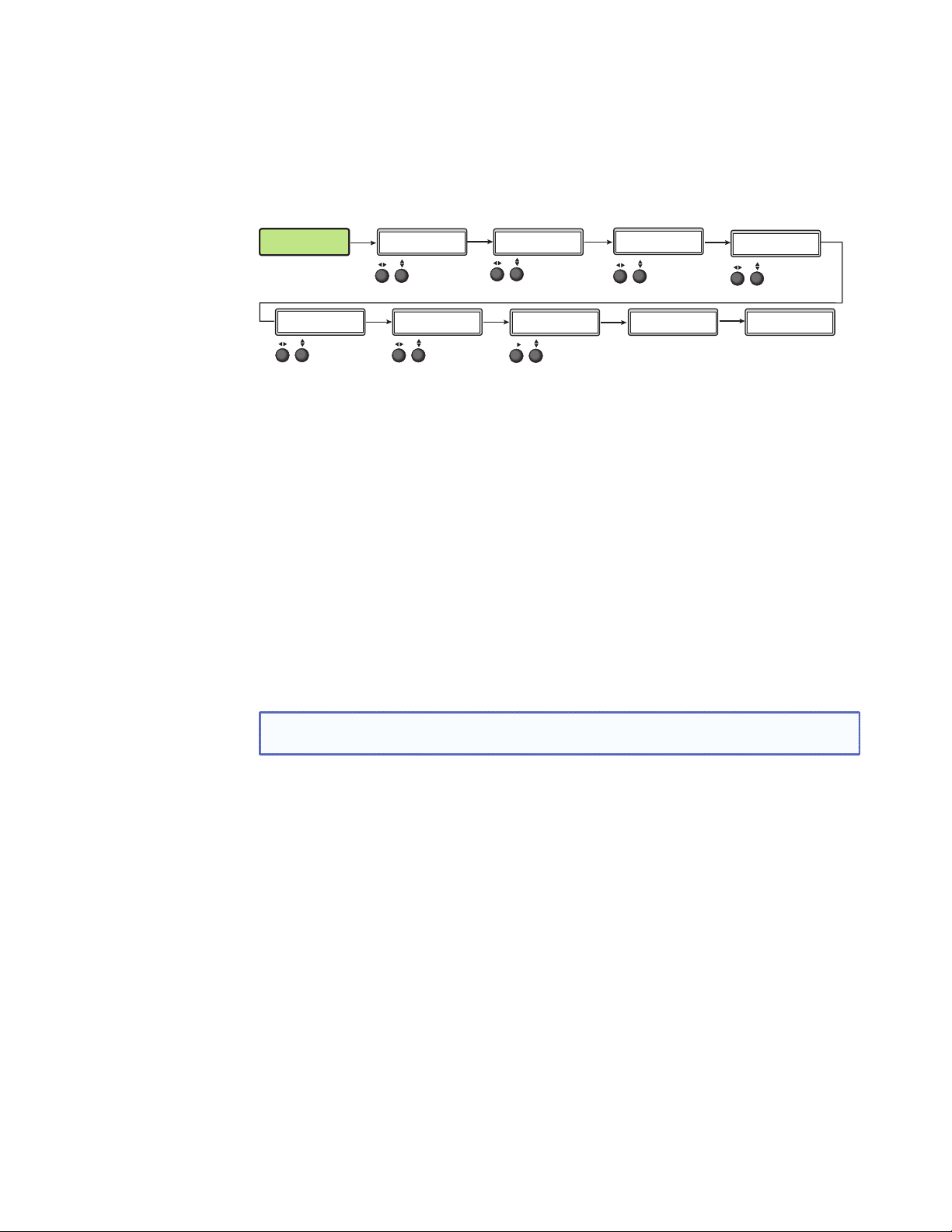
Advanced Configuration
The following flowchart provides an overview of the Advanced Configuration submenu
The options are Auto‑Image (on or off), aspect ratio (fill or follow), auto memory (on or off),
overscan (none, 2.5%, and 5.0%), switch type (dissolve or cut), test patterns (see table on
page 25), OSD duration, temperature (device reading only) and factory reset.
ADVANCED
CONFIG
SWITCH TYPE
DISSOLVE
Rotate either to
change switch
type.
Next
Next
AUTO IMAGE
IN#x Off
Rotate either to
turn Auto Image
mode on or off.
TEST PATTERN
COLOR BARS
Rotate either to
change test pattern.
Next
Next
ASPECT RATIO
IN#x FILL
Rotate either to select
aspect ratio mode.
OSD DURATION
125 SEC
Next
Rotate either to
set OSD duration.
AUTO MEMORY
IN#x ON
Rotate either to
turn auto memory
on or off.
Next
TEMPERATURE
96 F 35 C
Indicates internal temperature
(not adjustable).
Next
OVERSCAN
S-VIDEO 5.0%
Rotate either to set
overscan value.
Next
FACT. RESET
HOLD AUTO
Press and hold Auto button
to reset unit to factory settings.
Next
Figure 18. Advanced Configuration Menu
Aspect Ratio
Use either Adjust knob ([ {) to set the aspect ratio to Fill or Follow.
The aspect ratio setting is per input, and allows the user to select between each input
signal filling the entire output raster (Fill ‑ default setting), or for each input rate to be
displayed with its native aspect ratio (Follow ‑ 4:3, 5:4, 15:9, 16:9, 16:10) with the correct
letter box or pillar box settings visible under the Image Size and Image Position Picture
Controls.
When in the Fill mode, if an aspect ratio adjustment for a single input rate is desired, the
correct size and center can be set up using Image Size and Image Position under Picture
Controls, using one of the aspect ratio test patterns for a template. If auto memory is
enabled, then these settings are saved and recalled the next time the signal is detected.
The DVS 605 clears the previous size and position settings whenever the aspect ratio
setting for an input is adjusted.
NOTE: Unique SIS commands can set the device to Auto‑Image and Fill or
Auto‑Image and Follow, regardless of the current aspect ratio.
DVS 605 • Operation 23
Page 30

Auto-Image
Use either Adjust knob ([ {) to turn Auto‑Image on or off (default).
When enabled and a new input frequency is detected, the DVS first applies an existing
Auto Memory for the signal (if Auto Memory is enabled), or, if no entry exists, performs an
automatic Auto‑Image on the new signal. This automatically attempts to size/position the
image to fill the screen, with respect to the current aspect ratio setting.
With Auto‑Image disabled, the DVS 605 will apply default values to a new input if no
Auto Memory exists (if Auto Memory is enabled).
Auto-Image threshold settings
By default, the Auto‑Image function considers any analog video with a >25% brightness
to be active video. Some video sources, such as dark PC backgrounds, or dark borders
around a presentation, may require a lower “Auto‑Image threshold,” to ensure incoming
video is properly sized and centered by the Auto‑Image function. Other scenarios, such
as upstream analog twisted pair extension products, may require a greater Auto‑Image
Threshold setting in order to allow the DVS 605 to ignore extraneous sync pulses that
may have been embedded in the RGB signals.
A global analog video Auto‑Image threshold value can be set via an SIS command or
using internal web pages.
The range is 0% (black / ~0.0 VDC) to 100% (white / ~0.7 VDC), with a default value of
25%.
NOTE: The Auto‑Image threshold setting only affects analog input signals, and has no
effect on digital inputs, which are sized and centered automatically.
Auto Memory
Use either Adjust knob ([ {) to turn Auto Memory on (default) or off.
The DVS 605 stores 32 auto memories per input, with input configuration and picture
control data for each input. The default settings enable these memories to automatically
Auto Memory Auto-Image Information
recall input and picture controls for signals that have been previously applied. When auto
memories are disabled, the DVS treats every newly applied input as a new source. Default
for Auto Memory is on.
How Auto Memory and Auto-Image Interact
On On “New” signals/rates that have not been previously detected by the DVS are initially
On
(Default)
Off On Each change in input sync, input switch, or power cycle triggers an automatic Auto-
Off Off Each change in input sync causes default values to be applied to the rate. Any manual
Off
(Default)
set up using default parameters, then Auto-Image is automatically applied and values
stored. The next time that signal is detected, the values stored in the auto memory
location are applied.
“New” signals/rates that have not been previously detected by the DVS are set up using
default parameters. If manual input and/or picture settings are made to the input, an
auto memory location is created and recalled each successive time the input is detected.
Image. When auto memory is disabled, each change in sync is treated as a new signal
and an automatic Auto-Image is triggered. Any manual changes made to the image and
picture controls are lost each time a new rate is detected.
changes made to the image and picture controls are lost when a new rate is applied.
Figure 19. Auto Memory and Auto-Image Details
DVS 605 • Operation 24
Page 31

Overscan
Use the horizontal Adjust knob ([) to select input video type (RGB, YUV, RGBcvS,
S‑video, composite, or HDMI), and the vertical Adjust knob ({) to select the overscan
mode (None, 2.5% or 5.0%).
Overscan is specific to each input signal type. This zooms and crops SMPTE inputs to
mask edge effects and ancillary data that are common in broadcast signals. Issuing an
Auto‑Image with overscan enabled, runs an Auto Phase routine (YUV and RGB only) and
centers and sizes the input according to table values.
NOTE: Overscan is valid only on SMPTE input rates (NTSC, PAL, 480p, 576p, 720p,
1080i, or 1080p).
Switch type
This enables a video switch transition (cut or dissolve) when switching between inputs.
Use either of the Adjust knobs ([ {) to select the switch type as desired.
NOTE: Input switches between input 4 and input 5 use a fade through black
transition.
Test pattern
The built‑in test patterns are useful for calibrating a display to the DVS 605 output.
Choose a test pattern such as crop, alternating pixels, and color bars to adjust the image.
Color Bars
White Field
Figure 20. Test Pattern Choices
• Alternating Pixels — Used to calibrate input sampling of the display devices to the
Crosshatch
Crop
4x4 Crosshatch
1.33 Aspect
Grayscale
1.78 Aspect
Ramp
1.85 Aspect 2.35 Aspect
Alternating
Pixels
Alternating
Lines
Blue Mode
device output. Use this pattern to adjust the clocking and phasing at the display until
no more vertical bands are visible.
• Crop — Used to center the output on the display device: adjust H and V to
center the display until all four crop lines are visible.
• Color Bars — Used to calibrate color settings on the display and to confirm
proper system wiring.
• Blue Mode — This assists the user in setting up the color and tint levels
Use either the Adjust horizontal ([) or Adjust vertical ({) knob to select a test pattern. The
default state is Off.
OSD duration
The DVS 605 displays a small OSD “bug” in the upper left corner when switching between
input. This bug contains information regarding the detected input rate and format, the
HDCP status of the selected input, and an indication of Main vs. PIP inputs. The duration
that the OSD bug is on‑screen (in seconds) can be set from 1 to 500 seconds via the front
panel menu. It can also be set to “No OSD” or Always On”.
The duration can also be set via the internal web pages, or by SIS commands.
DVS 605 • Operation 25
Page 32

Temperature
This is a read‑only menu that gives the internal temperature (degrees C and F) of the
connected device. No adjustments can be made.
Factory Reset
This menu allows the user to reset the device to the factory default settings.
Press and hold the Auto‑Image button until the display changes. Release and press
Auto‑Image again to confirm that a reset is desired. The device will be reset.
View Comm Settings
The current RS‑232 and IP settings are read‑only with this menu. To make any setting
adjustments, the “hidden” Edit Comm Settings menu must be accessed (see below).
Press Next to go through each sublevel to view the following: serial port (baud rate and
communication type), MAC address (cannot be changed), DHCP status (on or off),
IP address, subnet mask, and gateway address.
NOTE: To enter the “hidden” Edit Comms Settings menu, press and hold in the input
5 and Next buttons simultaneously. The Edit Comms Settings menu appears.
Next
I 192.168
P 254.254
Rotate to select
octet field. Rotate
to change IP address.
Next
Next
SERIAL PORT
9600 RS232
Rotate to
change baud rate.
S 255.255
M 000.000
Rotate to select
octet field. Rotate
to change subnet
mask address.
EDIT COMM
SETTINGS
“Hidden” Menu
Figure 21. Edit Comm Settings Menu
Next
Next
DHCP MODE
<On>
Rotate either to
turn DHCP mode
On or Off.
G 192.168
W 000.000
Rotate to select
octet field. Rotate
to change gateway
address.
Next
Exit Menu
From this submenu, press the Menu button to return to the User Presets menu cycle, or
press the Next button to exit the menu and return to the default cycle.
DVS 605 • Operation 26
Page 33

Front Panel Lockout (Executive Modes)
sec.
V
80
z
720p
To prevent accidental changes to settings, press the Menu and Next buttons
simultaneously for 2 seconds to enable front panel lockout mode (executive mode 2).
The menu system returns to the default menu within 10 seconds.
Executive mode 2 locks all front panel functions except input switching, PIP enable and
PIP swap, and Auto‑Image. Menu and Next buttons and the Adjust knobs are disabled.
When executive mode 2 is active, all functions and adjustments can still be made
through USB, RS‑232, or Ethernet control. For details on remote control, see “SIS
Communications and Control” starting on page 34.
To disable executive mode 2, press the Menu and Next buttons simultaneously for
2 seconds. See the flowchart below.
In RGBH
#1 640x4
Output
Press both for
2 seconds
Menu
Next
EXEC. MODE 2
ENABLED
3 sec.
timeout
Enable Executive Mode
In 31.47 kHz
#1 59.94 H
@60
Press both for
2 seconds
Next
Menu
3 sec.
timeout
EXEC. MODE 2
DISABLED
Disable Executive Mode
Figure 22. Front Panel Lockout
Executive mode 1 locks all front panel functions completely. This mode can be enabled
or disabled by SIS commands only.
DVS 605 • Operation 27
Page 34

Window vs. Image Size Position — An Overview
The DVS 605 provides users the ability to adjust a window size/position and the
image’s (the content) size/position independently with regards to the output raster. This
independent control is available for both the Main and PIP windows allowing the user
comprehensive flexibility in output configurations.
The first example below demonstrates how a single sliver of an input (such as a stock
ticker or RSS Feed) can be displayed, while the remainder of the input is masked, by
setting the image size greater than the window size.
The second example demonstrates the flexibility of PIP mode. The Main window on the
left has the image size set to 4 x the window size, which effectively zooms into the top
right corner of the input, while masking the remainder of the input. The PIP window on the
right demonstrates the automatic aspect ratio compensation of the “Follow” mode, where
the image size and center are automatically adjusted to allow for the input to be shown at
its native aspect ratio
Figure 23. Examples of Window vs Image Size Position
NOTE: In PIP mode, the Fill and Follow calculations take place at each input switch,
power cycle, or whenever a new input signal is routed to the current input. The Fill
/ Follow calculations will adjust the image size and position in order to maintain the
input’s native aspect ratio with regard to the current window size.
DVS 605 • Operation 28
Page 35

Picture-in-picture (PIP) Mode
The DVS 605 can display two images on the screen simultaneously.
The PIP window can be activated using front panel PIP button, discrete SIS commands,
PIP presets, or the device embedded web pages. See “SIS Communication and
Control” starting on page 34, or “Using the Default Web Pages” starting on page 61
for details.
NOTE: Input 5 is not available for PIP mode.
Front Panel Activation
When the PIP window is enabled,
• the front panel PIP LED lights red.
• the PIP input LED lights red.
• the input LED for the main window lights green.
NOTES:
• Inputs 1 through 4 can be used in any combination for PIP mode.
• Input 5 is not selectable for PIP operation.
• Attempting to activate PIP mode while input 5 is selected results in the input 5 LED
blinking red/green for one second — LCD reads “IN5 PIP NOT AVAILABLE”.
• Attempting to select input 5 for the PIP input while PIP mode is active results
in the input 5 LED flashing red/off for one second — LCD reads “IN5 PIP
NOT AVAILABLE”.
• When in PIP mode, audio breakaway is not supported. Audio follows either
the main window or the PIP window, and is selectable via SIS command.
To start picture-in-picture mode:
1. Select an input for the main window input signal. The LED lights green.
2. Press the PIP button. The LED lights red, and the LED for input 1 or input 2 lights red.
3. Select another input as the PIP input, as desired. The corresponding LED lights red.
While the PIP mode is active, all front panel input selection, input configuration, and
picture control adjustments will affect the PIP window only.
When PIP is activated from the front panel, or via SIS command (not using PIP presets),
the DVS will automatically set up the last PIP layout with sizing and centering for the main
window, main image, PIP window, and PIP image. On a new unit, or after a reset, the DVS
defaults to the layout saved in PIP Preset #1
The inputs in the windows can be swapped using the front panel Swap button or a single
SIS command. See “SIS Communication and Control” for command details.
To swap between PIP and main inputs:
Press the Swap button. The input for the main window now becomes the new PIP input
and the LED changes from green to red. The previous PIP input becomes the new main
window input and the LED changes from red to green.
When PIP mode is not active, the Swap button swaps the current main input with the
previously selected main input.
DVS 605 • Operation 29
Page 36

PIP Presets
A PIP preset contains settings for the size and position of PIP window and which main
and PIP inputs that were active when the preset was saved. PIP presets are used to
quickly recall a group of settings that relate to the main and PIP windows and content
settings. Sixteen global PIP presets are available for the DVS 605.
A set of 10 factory default layouts exist and can be overwritten by saving new presets.
PIP presets can only be restored to factory defaults and not deleted.
1 234
PIP
MAIN
PIPPIP
5 678
MAIN MAIN
PIPPIP
MAIN MAIN
PIP PIP
MAINMAIN
910
PIP
MAIN
MAIN
PIP
MAIN
PIP
Figure 24. Default Main and PIP Window Layouts
A PIP preset can be created and saved using SIS commands or the embedded web
pages. See “SIS Communication and Control” starting on page 34, or “Using the
Default Web Pages” starting on page 61 for details.
PIP presets save the main and PIP inputs that were active when the preset was saved.
PIP presets can be recalled with or without inputs.
Presets
Setting Input Presets User Presets PIP Presets Auto Memory
Horizontal/Vertical Start Yes Yes
Active Pixels Yes Yes
Active Lines Yes Yes
Total Pixels Yes Yes
Phase Yes Yes
Brightness and Contrast Yes Yes Yes
Color and Tint Yes Yes Yes
Detail Yes Ye s Ye s
Input Type Yes
Audio Gain and Attenuation Yes
Main Window Size and Position Yes Ye s
PIP Window Size and Position Yes
Preset Name Yes Ye s Yes
Main Input Yes
PIP input Yes
Film Mode Yes
Presets Available 128 global 32 per input channel 16 per input
16 global
channel
Recall Location Any input that can support
the input type saved in
Automatically recalled
based in incoming signal
Current input Any input except
input 5
the preset
DVS 605 • Operation 30
Page 37

Other DVS 605 Operating Features
Screen Save
Screen Save mode allows the user to configure what will be displayed on the video
output, and for what duration, when the selected DVS 605 input loses an active video
signal. By default, the DVS 605 will continue to output muted (black) video and sync
indefinitely. Alternatively, users have the ability to display a blue screen with a moving text
“bug” that indicates that there is no active signal on the selected DVS 605 input.
A screen save duration can also be configured, which allows the user to set a duration
that the black or blue output video will be displayed, before output sync is disabled. By
disabling the output video sync, connected display devices can enter a low‑power, or
standby state to save lamp/panel life. The default duration is for output sync to never
timeout, but it can be configured to disable sync 0‑500 seconds after detecting no
active video input. Screen Save mode can be configured via the internal web pages (see
“Screen Saver Settings” section on page 81), or by SIS command (see “Screen saver
mode” commands, on page 48).
Power Save
The power save mode allows the user the ability to put the DVS 605 into a low power
state, via SIS command (see “Power Save Mode” on page 47), or the internal web
pages (see Executive/Power Mode Page on page 86). This state effectively cuts the
power consumption of the DVS 605 in half. While in this mode, no audio or video input
processing takes place, and all audio and video outputs are disabled. While in Power
Save mode, all front panel LEDs and LCD backlight are disabled, and the LCD will read
“STANDBY MODE.” The user has the ability to exit Power Save mode via front panel
button press, SIS command, or internal web pages. The Power Save state is entered
instantly after the associated command has been received, but 5‑10 seconds are required
to resume from the Power Save state.
Custom EDID/Custom Output Resolution
The user has the ability to capture EDID or import/upload EDID files to make custom EDID
available for emulation on inputs, or for the generation of custom output resolutions. The
user can import a 128 or 256 byte EDID “.bin” file from a PC, or can capture the EDID
from an attached sink (display) device. This EDID can then be saved and stored in one of
five custom EDID slots, which are then available for custom EDID emulation, or custom
output rate generation (custom rate based on the EDID preferred timings 1). These
functions are available via SIS (see “Input EDID” on page 42), or the internal web pages.
NOTE: Custom EDIDs do not have the audio blocks edited by the audio format setting.
Typically the audio capabilities presented in an HDMI input’s EDID are automatically
determined by the current audio format setting for the input. For example, when None or
Analog audio are set, the CEA extension block is omitted from the HDMI input EDID, to
ensure a source device provides audio on its analog outputs. In the 2Ch Digital and 2CH
Auto modes, a CEA EDID extension is emulated that contains support for only 2Ch LPCM
digital audio formats. In the Full Digital and Full Auto modes, a CEA EDID extension is
emulated that allows for all possible digital audio formats.
However, if a custom uploaded, or captured EDID is used for EDID emulation, the current
audio input setting of the HDMI input has no effect on the described audio capabilities
contained within the custom EDID file. The DVS 605 simply presents the custom EDID file
without any modifications. The Audio Format setting continues to determine which audio
source is used for the HDMI input (none, analog audio, or embedded digital audio).
DVS 605 • Operation 31
Page 38

Audio Format Audio Source Analog Input Digital Inputs EDID
None Muted Yes Yes No CEA
Analog
LPCM-2Ch Embedded Digital No Ye s
5‑Pole Captive Yes Yes No CEA
LPCM‑2Ch CEA
Multi-Ch Embedded Digital No Ye s Multi‑Ch CEA
LPCM-2Ch Auto Embedded Digital
No Ye s LPCM‑2Ch CEA
(when present), else
5‑Pole Captive
Multi-Ch Auto Embedded Digital
No Ye s Multi‑Ch CEA
(when present), else
5‑Pole Captive
NOTE: If one of the custom EDID slots is in use, the audio format setting will have no
effect on the emulated EDID table.
It is important that care should be taken when assigning custom EDID files, as the
user can potentially assign an analog (VGA) EDID to a digital (HDMI) input, or vice versa. If
an EDID file listing support for the incorrect video format has been assigned, the attached
source may not output any video, or unexpected behavior may result.
The OSD Bug
When switching between inputs, the DVS 605 will display a small OSD “bug” in the upper
left corner. This bug contains information regarding the detected input rate and format,
the HDCP status of the selected input, and an indication of Main vs. PIP inputs. The OSD
bug can be disabled by setting the OSD duration to 0.0 seconds via the front panel, the
internal web pages, or by SIS commands.
The items displayed are:
• Main vs. PIP
• Detected input rate
• HDCP Lock
Hardwired IR Port
The DVS 605 includes a hardwired IR input, to be used with a hardwired IR output from
an Extron MLC, IPL, or similar controller. This port allows for simple, unidirectional control
of the DVS 605 from a host controller that has no available RS‑232 ports, but does have
available hardwired IR outputs.
Using the DVS 605 IR driver, available from the Extron website, basic controls include:
• Input Switching
• Auto‑Image, Auto‑Image + Fill, Auto‑Image + Follow
• Audio Mute, Video Mute, A/V Mute
• Volume
• PIP On/Off, PIP Swap
• User Presets Recall 1, 2, and 3 (for the selected input)
• PIP Preset Recall 1 – 6 (with or without input)
• Show Informational On Screen Display (OSD)
NOTE: There is no available IR remote for the DVS 605.
DVS 605 • Operation 32
Page 39

Resetting the Unit
There are three unit reset modes (numbered 1, 4, and 5), These are available by pressing
the recessed Reset button on the rear panel with a pointed stylus, pen, or similar item to
access it. See the following table for a summary of the reset modes.
ATTENTION: Review the reset modes carefully. Using the wrong reset mode may
NOTE: The reset modes listed closes all open IP and Telnet connections and all
Mode Activation Result Purpose and Notes
Hold down the recessed Reset
1
button while applying power to the
unit.
result in unintended loss of flash memory programming, port reassignment, or
processor reboot.
sockets. Each mode is a separate function, and not a continuation from mode 1
to mode 5.
DVS 605 Reset Mode Summary
The unit reverts to the factory default
firmware:
a) Reverts to the factory default firmware
for a single power cycle.
b) All user files and settings (drivers, audio
and video adjustments, IP settings, etc.)
are maintained.
Use mode 1 to revert to the factory
default version if incompatibility
issues arise with user‑loaded
firmware.
NOTE: After a mode 1 reset
is performed, update the
firmware of the unit to the
latest version. Do not operate
the device firmware version
Use Factory Firmware
4
Settings
Reset All IP
5
Reset to Factory Defaults
that results from the mode 1
reset. This temporarily resets
the unit to factory default until
power is recycled. If you want
to use the factory default
firmware, you must upload
that version again.
Hold down the Reset button for
about 6 seconds until the LED blinks
twice (once at 3 seconds, once at 6
seconds). Then, release and press
Reset momentarily (for <1 second)
within 1 second*.
Hold down the Reset button for
about 9 seconds until the LED blinks
three times (once at 3 seconds, once
at 6 seconds, once at 9 seconds).
Then, release and press Reset
momentarily (for <1 second) within 1
second*.
NOTE: If you do not want to update
firmware, or you performed a mode 1
reset by mistake, cycle power to the
unit to return to the firmware version
that was running prior to the mode
1 reset. Use the 0Q SIS command
to confirm that the factory default
firmware is no longer running (look for
asterisks following the version number).
a) Sets port mapping back to factory default
b) Turns DHCP off ‑ sets IP to default address
(192.168.254.254)
c) Reset LED flashes four times in quick
succession during reset.
Mode 5 performs a complete reset to factory
defaults except the firmware.
a) Does everything mode 4 does.
b) Resets all user modifiable configuration to
default values including IP settings and
real‑time adjustments.
c) Deletes all user loaded files.
d) The Reset LED flashes 4 times in quick
succession during the reset.
Mode 4 resets all IP settngs back
to factory defaults.
Mode 5 is useful if you want to
restart with default configuration.
Equivalent to SIS command ZQQQ.
NOTE: *For modes 4 and 5, nothing happens if the momentary press does not occur within 1 second
Figure 25. Reset Mode Comparison
DVS 605 • Operation 33
Page 40

SIS Communication and Control
The DVS 605 can be configured and controlled via a host computer or other device (such
as a control system) attached to the rear panel RS-232 connector or the LAN port or the
front panel USB port. Control is made using the Extron Simple Instruction Set (SIS) of
commands, or the DVS default web pages.
Commands can be entered using a Telnet application such as the Extron DataViewer,
available at www.extron.com. See the DataViewer Help file for use.
This section describes SIS communication and control. Topics that are covered include:
• Host to Scaler Communications
• Commands and Responses
The scaler uses a protocol of 9600 baud, 1 stop bit, no parity, and no flow control and the
rear panel RS-232 captive screw connector has the pin assignments as shown.
Host to Scaler Communications
RS-232 / IR
Tx Rx
GG
IR
SIS commands consist of one or more characters per field. No special characters are
required to begin or end a command sequence. When the DVS 605 determines that a
command is valid, it executes the command and sends a response to the host device.
All responses from the scaler to the host end with a carriage return and a line feed
(CR/LF = ]), indicating the end of the response character string (one or more characters).
Scaler-initiated Messages
When a local event such as a front panel selection or adjustment takes place, the DVS 605
scaler responds by sending a message to the host. No response is required from the host.
Example scaler-initiated messages are listed here.
• ] © Copyright 2012, Extron Electronics, DVS 605, Vx.xx, 60-1059-
01
] Thur, 17 February 2012 11:27:33 ] The DVS 605 sends the copyright
message when it first powers on. Vx.xx is the firmware version number.
• In X! All ] (where X! is the input number during an input switch).
• Reconfig ] The DVS 605 sends this response when an input is switched or when a
new signal is detected.
Copyright Information
] © Copyright 2012, Extron Electronics, DVS 605, Vx.xx, 60-1059-
01
] Thur, 17 February 2012 11:27:33 ]] © Copyright 2012, Extron
Electronics, DVS 605, Vx.xx, 60-1059-01
11:27:33
The copyright message is displayed upon connecting to an DVS product via TCP/IP or
Telnet. Vx.xx is the firmware version number. The current date and time are displayed.
This is followed by a Password prompt if a password has been set.
]
] Thur, 17 February 2012
DVS 605 • SIS Communication and Control 34
Page 41

Password Information
The ] Password: prompt requires a password (administrator level or user level) followed
by a carriage return. The prompt is repeated if the correct password is not entered.
If the correct password is entered, the unit responds with ] Login Administrator ]
or ] Login User ], depending on password entered. If passwords are the same for
both administrator and user, the unit defaults to administrator privileges.
Error Responses
When the DVS 605 receives a valid command, it executes the command and sends a
response to the host device. If the unit is unable to execute the command because the
command contains invalid parameters, it returns an error response to the host.
Error Numbers
E01 — Invalid input number E17 — Invalid command for signal type
E06 — Invalid switch attempt in this mode E22 — Busy
E10 — Invalid command E24 — Privilege violation
E11 — Invalid preset number E25 — Device not present
E12 — Invalid port number E26 — Maximum number of
connections exceeded
E13 — Invalid parameter E28 — Bad filename/file not found
E14 — Not valid for this configuration
Error Response References
14
= Commands that give an E14 (invalid command for this configuration) error if sent
to a product whose current configuration does not support the command
24
= Commands that give an E24 (privilege violation) error if not logged in at administrator
level
28
= Commands that may give an E28 (file not found) error
Commands and Responses
Using the Command and Response Tables
The command and response tables for SIS commands from page 42 onwards lists the
commands the DVS 605 recognizes as valid. The tables show the responses that are
returned to the host with a description of the command function or command execution
results. Also included are examples of command in ASCII (Telnet) and URL encoded (web).
NOTE: Upper and lower case text can be used interchangeably.
ASCII to HEX Conversion Table
Space
•
Figure 28. ASCII to Hexadecimal Character Conversion Table
DVS 605 • SIS Communication and Control 35
Page 42

Symbol Definitions
•=Space
] = Carriage return with line feed
¦ or} = Carriage return with no line feed
E
or W = Escape
14, 24, 28
= Superscripts indicate the error message displayed if the command is entered
incorrectly or with invalid parameters. See “Error Response References,” on page 35.
X! = Input selection, 1-5, (0 = current input — 0 is valid only for Input Config settings:
0 = main when PIP is disabled, 0 = PIP when PIP is enabled)
X@ = Output selection:
0 = All outputs (default)
1 = Analog (VGA, YUVp, HDTV)
2 = HDMI
3 = 3G/HD-SDI
4 = None
X# = Input video format:
0 = No signal detected (only valid for detected input format query, such as X!*\ or “ I”)
1 = RGB 5 = Composite video
2 = YUV auto 6 = DVI/HDMI (available only for inputs 3, 4, and 5)
3 = RGBcvS 7 = Auto detect (default for inputs 1 and 2)
4 = S-video
X$ = Horizontal/vertical start — 0 to 255 (default midpoint = 128)
X% = Pixel phase — 0 to 63 (default = 31)
X^ = Total pixels — ±512 of the default value
X& = Active pixels — ±512 of the default value
X* = Active lines — ±512 of the default value
X( = Enable/disable: 0 = Off/disable, 1 = On/enable
X1) = Input standard:
0 = No signal detected 3 = NTSC 4.43
1 = NTSC 3.85 4 = SECAM
2 = PAL
- = N/A (occurs when input is an active RBG, YUV auto [but not NTSC/PAL], or HDMI signal)
X1! = Internal temperature (in degrees Celsius)
X1@ = Unit name is a text string of up to 24 characters drawn from the alphabet (A-Z), digits (0-9),
and the minus sign/hyphen (-). The first character must be an alpha character. The last
character must not be a minus. No blank or space characters are permitted, and no distinction
is made between upper- and lowercase.
X1# = Horizontal and vertical frequencies (format is three-digit with single decimal and leading zeros
for example, 075.3
X1$ = Text label/preset name: up to 16 characters
)
NOTE: User and input presets saved without a name are saved with the default names
“User Preset xx” (for example, User preset 12) or “Input preset xxx” (for example,
input preset 122).
X1% = Picture adjustment — 0 to 127 (default = 64)
X1^ = Horizontal and vertical position, ±11000, with leading “+” or “-”, for example “- 02040”
DVS 605 • SIS Communication and Control 36
Page 43

X1& = Horizontal and vertical size, 0 to 11000
X1* = Image/window number: 1 = main window, 2 = PIP window
X1( = Scaler resolution/EDID emulation:
0 = Automatic: match current output resolution (default for EDID emulation) LCD reads
Match Output
1 = Output 1 (analog VGA connector — available for Save and Export EDID commands only)
2 = Output 2 (HDMI connector — available for Save and Export EDID commands only)
3 = Custom EDID/output rate 1 6 = Custom EDID/output rate 4
4 = Custom EDID/output rate 2 7 = Custom EDID/output rate 5
5 = Custom EDID/output rate 3 10-92: see table below
X1(
SIS
Resolution 23.98 Hz 24 Hz 25 Hz 29.97 Hz 30 Hz 50 Hz 59.94 Hz 60 Hz 75 Hz
640x480 10 11 12
800x600 13 14 15
852x480 16 17 18
1024x768 19 20 21
1024x852 22 23 24
1024x1024 25 26 27
1280x768 28 29 30
1280x800 31 32 33
1280x1024 34 35 36
1360x765 37 38 39
1360x768 40 41 42
1365x768 43 44 45
1366x768 46 47 48
1365x1024 49 50 51
1440x900 52 53 54
1400x1050 55 56
1600x900 57 58
1680x1050 59 60
1600x1200 61 62
1920x1200 63 64
480p 65 66
576p 67
720p 68 69 70 71 72 73*
1080i 74 75 76
1080p 77 78 79 80 81 82 83 84
2048x1080 2k 85 86 87 88 89 90 91 92
variables for EDID resolution/refresh rate combination (where
X1( = 10 through 92)
*
Default output resolution
Figure 29. SIS Command EDID Table
X2) = Test patterns:
0 = Off (default) 8 = Ramp
1 = Crop 9 = White field
2 = Alternating pixels 10 = 1.33 aspect ratio
3 = Alternating lines 11 = 1.78 aspect ratio
4 = Crosshatch 12 = 1.85 aspect ratio
5 = 4x4 crosshatch 13 = 2.35 aspect ratio
6 = Color bars 14 = Blue mode
7 = Grayscale
DVS 605 • SIS Communication and Control 37
Page 44

X2! = Analog output polarity:
0 = H-/V- (default)
1 = H-/V+
2 = H+/V 3 = H+/V+
X2@ = Analog output sync format:
0 = RGBHV (default)
1 = RGBS
2 = RGsB
3 = Y, R-Y, B-Y bi-level
4 = Y, R-Y, B-Y tri-level
X2# = User presets or PIP presets — 1 to 16
X2$ = Input presets — 1 to 128
X2% = On-screen menu time-out or screen saver sync timeout, (default = 3 seconds)/output sync
time-out (default = 501 - never)
0 = OSD is never displayed/output sync is instantly disabled with no active input
1 to 500 in 1 second increments,
501 = OSD never times out, output sync is never disabled
X2^ = Executive mode status:
0 = Off/disable, (default)
1 = Exec mode 1 — Complete front panel lockout
2 = Exec mode 2 — Partial front panel lockout (only input selection, Auto-Image, and
PIP/Swap are still available)
X2& = PIP window input selection: 0 to 4 (0 = off). (Input 5 is not available for PIP mode.)
X2* = Overscan (applied to SMPTE [NTSC, PAL, 480p, 576p, 720p, 1080i, 1080p] input rates):
0 = 0.0% (default for RGB/HDMI),
1 = 2.5% (default for YUV, RGBcvS, S-video, composite)
X2( = Aspect ratio:
1 = Fill: each input rate will automatically fill the entire output raster (default)
2 = Follow: each input rate will be displayed with its native aspect ratio
X3) = Screen saver mode:
1 = Black screen (default)
2 = Blue screen with OSD text
X3! = Video mute:
0 = off/disable
1 = on/enable (mute to black)
2 = mute output sync and video
X3@ = Auto-Image threshold value: 0 (black) though 100 (white), default = 25
X3# = HDCP status (valid only on HDMI/DVI outputs):
0 = No sink or source detected
1 = Sink or source detected with HDCP
2 = Sink or source detected but no HDCP is present
X3% = Video switching duration:
from 2 (0.2 sec) to 50 (5.0 sec). Default value is 3 or 0.3 sec
DVS 605 • SIS Communication and Control 38
Page 45

X3^ = HDMI output format:
0 = Auto (based on sink EDID), default
1 = DVI
2 = HDMI 444 RGB (0-255, audio, InfoFrames)
3 = HDMI 444 YUV “FULL” (0-255, audio, InfoFrames)
4 = HDMI 444 YUV “LIMITED” (16-235, audio, InfoFrames)
5 = HDMI 422 YUV “FULL” (0-255, audio, InfoFrames)
6 = HDMI 422 YUV “LIMITED” (16-235, audio, InfoFrames)
X3& = Auto switch mode:
0 = Disable (default)
1 = Gives priority to the highest input
2 = Gives priority to the lowest input
X3* = Audio volume range: -100 dB to 0 dB, in 1.0 dB steps, default = -30 dB (with leading “-”);
where 0 = 0 dB (max volume output)
X3( = Audio output format:
1 = Dual mono
2 = Stereo (default)
X4) = Audio gain/Attenuation: -53 through + 09 dB, (with leading “+” or “–“)
X4! = Audio source:
0 = Follow Main window
1 = Follow PIP window
2 = Toggle source
X4@ = Audio input type:
0 = None, input is muted (EDID has no CEA extension)
1 = Analog, 5-pole captive screw (EDID has no CEA extension)
2 = 2Ch digital, embedded in HDMI input, (2Ch PCM audio requested from source via EDID)
3 = Full digital (via EDID to allow any digital audio format from source)
4 = 2Ch digital, Auto (2Ch PCM audio requested from source via EDID), scaler uses embedded
digital audio when present, or defaults to the input’s analog 5-pole captive screw
5 = Full digital auto (Full audio is requested from source via EDID). Scaler uses embedded
digital audio when present, or defaults to input’s analog 5-pole captive screw.
NOTES: • Inputs 1 and 2 can only be set to X4@ = 0 (all models) or 1 (audio model only).
Attempting to set these inputs to any other format gives an “E14” error message.
• Non-audio models of the DVS 605 will allow X4@ = 0 on inputs 1 and 2, and
X4@ = 0, 2, or 3 on inputs 3, 4, and 5.
X4# = Static audio delay, 0 through 255 milliseconds (default is 0)
NOTE: The static audio delay is in addition to the automatic audio delay that is
applied by the DVS 605 to compensate for internal video processing.
X4$ = Video signal status
0 = Video / TMDS signal not detected
1 = Video / TMDS signal detected
X4% = Power save modes
0 = Full power mode (default)
1 = Low power state
X4^ = Screen saver status
0 = Active input detected; timer not running
1 = No active input; timer is running; output sync still active
2 = No active input; timer has expired; output sync disabled
DVS 605 • SIS Communication and Control 39
Page 46

X4& = Input signal/SDI genlock
0 = Disabled; (default)
1 = Input signal genlock enabled; locks output vertical to the selected input vertical rate
2 = SDI genlock enabled; locks output vertical to the applied genlock input (“D” models only)
X4* = Input signal/genlock status
0 = Input signal / SDI genlock disabled
1 = Input signal / SDI genlock enabled, but cannot lock to applied input signal/SDI genlock
input. DVS defaults to set output rate/refresh
2 = Input signal/SDI genlock enabled, output locked to applied input signal/SDI genlock input
X4( = Input HDCP HDMI authorization status:
0 = Block HDCP encryption
1 = Allow HDCP encryption (default for inputs 3, 4, and 5)
X5) = Horizontal genlock offset: range is ± the correct output resolution total pixel value -1
(for example, -2199 to +2199 for 1080p)
X5! = Vertical genlock offset: range is ± the correct output resolution total line value -1
(for example, -1124 to +1124 for 1080p)
SIS IP command definitions
X10) = Default name: combination of model name and last 3 hex pairs of MAC address
(for example DVS-605-Series-07-8C-EC).
X10$ = On/off status: 0 = off/disable; 1 = on/enable
X10^ = Unit name is a text string up to 24 characters drawn from the alphabet (A-Z), digits (0-9),
minus sign/hyphen (-). No blank or space characters are permitted as part of a name.
No distinction is made between upper and lower case. The first character must be an alpha
character. The last character must not be a minus sign/hyphen.
X10& = Local date and time format
Set format is MM/DD/YY-HH:MM:SS; for example, 06/21/02-10:54:00
Read format is day, date month year (HH:MM:SS), for example, Thu, 20 Feb 2003 (18:19:33)
X10* = IP address (xxx.xxx.xxx.xxx); leading zeros in each of 4 fields are optional in setting
values, and are suppressed in returned values.
NOTE: DHCP is disabled by default. Default IP is 192.168.254.254.
X10( = Hardware (MAC) address (00-05-A6-xx-xx-xx).
X11) = Subnet mask (xxx.xxx.xxx.xxx). Leading zeros are optional in setting values in each of four
fields, and are suppressed in returned values. Default subnet mask = 255.255.0.0
X11! = Verbose/Response mode, (default = 0 for telnet connections, 1 for RS-232 and USB host
control).
0 = Clear/none;
1 = Verbose mode
2 = Tagged responses for queries
3 = Verbose mode and tagged responses for queries.
NOTE: If tagged responses is enabled, all read commands will return the constant string +
the data, like setting the value does.
For example command: E CN } response: Ipn • X10^]
X12! = Password (12 characters = maximum length; no special characters are allowed.)
NOTE: A user password cannot be assigned if no administrator password exists; the E14
error code is returned. If the administrator password is cleared, the user password is
also removed.
DVS 605 • SIS Communication and Control 40
Page 47

X12% = Connections security level:
0 = anonymous, 11 = user,
1 – 10 = extended security levels 1 thru 10 12 = Administrator
X12& = The number of seconds before timeout on the IP connection: min. = 1; max. = 65000;
(default = 30 = 300 seconds). If no data is received during the timeout period, the
Ethernet connection is closed. Each step = 10 seconds. Applicable only when
connected via Ethernet. When connected via RS-232 only the global timeout
commands apply (current returns E13). Response is returned with leading zeros.
X13! = Firmware Query (‘Q’ commands)
*Q = Firmware and build number [<X.YY.ZZZZ> ]
0Q = Verbose version information [<2Q> - <3Q> - < 4Q>] sum of responses from 2Q-3Q-4Q
1Q = Firmware version [<currently running code (X.YY)>]
2Q = Final stage bootloader (Uboot) version [<X.YY>]
3Q = Factory base code version [<factory base code (X.YY)>*<kernel version (X.YY) –
description – date loaded >]
4Q = Updated firmware version [<updated code version (X.YY)>*<kernel version (X.YY) –
description – date loaded >]
NOTE: For 3Q and 4Q, an asterisk ‘*’ after version number indicates which version is
currently running. A question mark (?.??) indicates that only the factory firmware
version is loaded. A caret (^) indicates the firmware version that should be running,
but a Mode 1 reset was executed and the default factory firmware version is loaded.
An exclamation point (!) indicates corrupted firmware.
[Example: 1.03*(1.42-DVS 605 -Thur, 21 Apr 2012 22:30:57 GMT).]
The SIS Command and Response tables start on the next page.
DVS 605 • SIS Communication and Control 41
Page 48

SIS Command and Response Table
Command ASCII Command
(host to scaler)
Response
(scaler to host)
Additional Description
Input selection
Video and audio
Video
Audio
View video input
View audio input
View current input
X!! In X!•All]
X!& In X!•RGB]
X!$ In X!•Aud]
&
$
!
X!]
X!]
X!]
Select video and audio from input X!.
Select video from input source X!.
Select audio from input source X!.
View current video input X!.
View current audio input X!.
View current selected input X! (video only).
NOTES: See “Video only and Audio only switching (breakaway) Rules“ on page 64 for details
•Audio breakaway ($) is not allowed TO an input configured for any digital audio format.
•Video breakaway (&) is not allowed FROM an input configured for any digital audio format.
•Attempting either of these invalid modes gives an E17 error.
•Audio breakaway is always allowed back TO the current video input.
•When in PIP mode, audio breakaway is not supported. Audio follows either the main window or the
PIP window, and is selectable via SIS command.
Input video format
Set video format
View set format
View detected
format
X!*X#\ TypX!*X#]
X!\
X#]
X!*\ X#]
VTypX!*X#]
Set input X! to format X#.
View set video format of input X!.
View actual video format autodetected on
input
X!.
Verbose mode response
Input EDID (VGA and HDMI)
Assign EDID to
input
View assigned EDID
data
Capture an output
EDID to custom slot
Export EDID file
EAX!*X1(EDID} EdidAX!*X1(]
EAX!EDID}
X1(]
EdidAX!*X1(]
ESX@*X1(EDID} EdidSX@*X1(]
EEX1(,<filename>
EdidEX1(]
Assign EDID resolution and refresh rate
X1( for input X!.
View assigned EDID resolution and refresh
rate
X1( for input X!.
Verbose mode response
Capture output X@ EDID to X1(
(Valid for X1( = 3, 4, 5, 6, 7 only and X@ =
1 or 2 only.)
Exports EDID table X1( to <filename>.
EDID}
Import EDID file
EIX1(,<filename>
EDID}
EdidIX1(]
Imports EDID table X1( from
<filename>.
Import valid for
X1( = 3, 4, 5, 6, and 7.
NOTE: <filename> can optionally carry a full path name: EDID file format is “bin” carrying 128 or 256 bytes of binary
data.
Exporting a default EDID table (for an X1( value of 10 or greater) results in the “digital” “2CH Digital” table
being exported.
NOTE: X! = Input number: 1 through 5
X@ = Output selection: 0 = All outputs (default), 1 = Analog (VGA, YUVp, HDTV), 2 = HDMI, 3 = 3G/HD-SDI, 4 = None
X# = Input video format: 0 = No signal detected, 1 = RGB, 2 = YUV auto, 3 = RGBcvS, 4 = S-video, 5 = Composite,
6 = DVI/HDMI (only available for inputs 3, 4, and 5), 7 = Auto detect (default for inputs 1 and 2)
X1( = Scaler resolution/EDID emulation, 0 = Automatic: match current output resolution (default),1 = Output 1 analog
VGA connector, 2 = Output 2 HDMI connector, 3 = Custom EDID/output rate 1, 4 = Custom EDID/output rate 2,
5 = Custom EDID/output rate 3, 6 = Custom EDID/output rate 4, 7 = Custom EDID/output rate 5.
For variables 10-78, see the SIS EDID table on page 36.
DVS 605 • SIS Communication and Control 42
Page 49

Command ASCII Command
(host to scaler)
Response
(scaler to host)
Additional Description
Input name
Write input name
Read input name
EX!,X1$NI} NmiX!,X1$]
EX!NI}
X1$]
Set the name X1$ for input X!.
View input X! name X1$.
NOTE: To clear an input name, a single space character should be entered for X1$. This resets the input name to the
default value.
Auto-Image
Enable
Disable
View status
Execute
Execute and Fill
Execute and Follow
X!*1A ImgX!*1]
X!*0A ImgX!*0]
X!A X(]
0*A Img0]
1*A Img1]
2*A Img2]
Activate Auto-Image for input X!.
Turn Auto-Image off for input X!.
View Auto-Image setting: (0 = on,
1 = off).
Execute an Auto-Image to the selected
input (follows current aspect setting).
Execute an Auto-Image and fill entire
output.
Execute an Auto-Image and follow the
aspect ratio of the input.
Auto-Image threshold value (minimum luminosity value which the scaler defines as active video for Auto-Image)
Set value
EX3@ALVL} AlvlX3@]
Set global Auto-Image luminosity value
X3@.
View
EALVL} X3@]
View global Auto-Image luminosity value
X3@.
Horizontal start
Specify a value
Increment value
Decrement value
View
EX!*X$HSRT} HsrtX!*X$]
EX!+HSRT} HsrtX!*X$]
EX!-HSRT} HsrtX!*X$]
EX!HSRT}
X$]
Set horizontal location of first active pixel
for input
Increment horizontal start position.
Decrement horizontal start position.
Show horizontal location of first active
pixel for input
X!.
X!.
Vertical start
Specify a value
Increment value
Decrement value
View
EX!*X$VSRT} VsrtX!*X$]
EX!+VSRT} VsrtX!*X$]
EX!-VSRT} VsrtX!*X$]
EX!VSRT}
NOTE: X! = Input selection: 1 to 5
X$ = Horizontal/vertical start: 0 to 255 (default midpoint = 128)
X( = Enable/disable: 0 = off/disable, 1 = on/enable
X1$ = Text label/preset name, up to 16 characters
X3@ = Auto-Image threshold value: 0 (black) though 100 (white), default = 25
X$]
Set vertical location of first active pixel for
input
X!.
Increase vertical start.
Decrease vertical start.
Show vertical location of first active pixel
for input
X!.
DVS 605 • SIS Communication and Control 43
Page 50

Command ASCII Command
(host to scaler)
Response
(scaler to host)
Pixel phase (available only for RGB and YUV auto input signals)
Specify a value
Increment value
Decrement value
View
EX!*X%PHAS} PhasX!*X%]
EX!+PHAS} PhasX!*X%]
EX!-PHAS} PhasX!*X%]
EX!PHAS}
X%]
Total pixels (available only for RGB and YUV auto input signals)
Specify a value
Increment value
Decrement value
View
EX!*X^TPIX} TpixX!*X^]
EX!+TPIX} TpixX!*X^]
EX!-TPIX} TpixX!*X^]
EX!TPIX}
X^]
Active pixels
Specify a value
Increment value
Decrement value
View
EX!*X&APIX} ApixX!*X&]
EX!+APIX} ApixX!*X&]
EX!-APIX} ApixX!*X&]
EX!APIX}
X&]
Active lines
Specify a value
Increment value
Decrement value
View
EX!*X*ALIN} AlinX!*X*]
EX!+ALIN} AlinX!*X*]
EX!-ALIN} AlinX!*X*]
EX!ALIN}
X*]
3:2, 2:2, and 24:1 Film mode autodetect
Enable autodetect
Disable autodetect
View setting
EX!*1FILM} FilmX!*1]
EX!*0FILM} FilmX!*0]
EX!FILM}
X(]
Additional Description
Adjust the pixel phase to specified value X%
for input X!.
Increase the pixel phase.
Decrease the pixel phase.
Show the pixel phase for input X!.
Adjust the total pixels to specified value X^
for input X!.
Increase the total pixels.
Decrease the total pixels.
Show the total pixels for input X!.
Adjust the active pixels to a specified value
X& for input X!.
Increase the active pixels.
Decrease the active pixels.
Show the active pixels for input X!.
Adjust the active lines to a specified value
X* for input X!.
Increase the active lines.
Decrease the active lines.
Show the active lines for input X!.
Enable film mode autodetection.
Disable film mode autodetection.
View the currently applied film mode
detection setting.
NOTE: X! = Input selection: 1 to 5
X% = Pixel phase: 0 to 63 (default = 31)
X^ = Total pixels: ±512 of the default value
X& = Active pixels: ±512 of the default value
X* = Active lines: ±512 of the default value
X( = Auto/off: 0 = off/disable, 1 = on/enable
DVS 605 • SIS Communication and Control 44
Page 51

Command ASCII Command
(host to scaler)
Picture Adjustments
Video mute
Mute all outputs to
black
Mute all sync and
video
Unmute all outputs
View
1B Vmt1]
2B Vmt2]
0B Vmt0]
B
Color
Set a specific value
Increment value
Decrement value
View
EX!*X1%COLR} ColrX!*X1%]
EX!+COLR} ColrX!*X1%]
EX!-COLR} ColrX!*X1%]
EX!COLR}
Tint
Set a specific value
Increment value
Decrement value
View
EX!*X1%TINT} TintX!*X1%]
EX!+TINT} TintX!*X1%]
EX!-TINT} TintX!*X1%]
EX!TINT}
Response
(scaler to host)
X3!]
X1%]
X1%]
Additional Description
Mutes video and displays black video on all
outputs.
Mutes sync and video on all outputs.
Unmutes all outputs.
View the mute status (0 = disabled, 1 =
enabled - mute to black, 2 = mute output
sync and video).
Set color level to X1% for input X!.
Increment color level.
Decrement color level.
View current setting for input X!.
Set tint level to X1% for input X!.
Increment tint level.
Decrement tint level.
View current setting for input X!.
Contrast
Set a specific value
Increment value
Decrement value
View
Brightness
Set a specific value
Increment value
Decrement value
View
Detail filter
Set detail level
Increment value
Decrement value
View detail value
EX!*X1%CONT} ContX!*X1%]
EX!+CONT} ContX!*X1%]
EX!-CONT} ContX!*X1%]
EX!CONT}
X1%]
EX!*X1%BRIT} BritX!*X1%]
EX!+BRIT} BritX!*X1%]
EX!-BRIT} BritX!*X1%]
EX!BRIT}
X1%]
EX!*X1%HDET} HdetX!*X1%]
EX!+HDET} HdetX!*X1%]
EX!-HDET} HdetX!*X1%]
EX!HDET}
X1%]
Set contrast level to X1% for input X!.
Increment contrast level.
Decrement contrast level.
View current setting for input X!.
Set brightness level to X1% for input X!.
Increment brightness level.
Decrement brightness level.
View current setting for input X!.
Specify the detail level to X1% for input X!.
Increase the detail level.
Decrease the detail level.
Show the detail setting for input X!.
NOTE: X! = Input selection: 1 to 5
X1% = Picture adjustment: 0 to 127 (default = 64)
X3! = Video mute: 0 = off/disable, 1 = on/enable (mute to black), 2 = mute output sync and video
DVS 605 • SIS Communication and Control 45
Page 52

Command ASCII Command
(host to scaler)
Horizontal position (window)
Specific value
Increment value
Decrement value
View
E1*X1**X1^HCTR} Hctr1*X1**X1^]
E1*X1*+HCTR} Hctr1*X1**X1^]
E1*X1*-HCTR} Hctr1*X1**X1^]
E1*X1*HCTR}
Vertical position (window)
Specific value
Increment value
Decrement value
View
E1*X1**X1^VCTR} Vctr1*X1**X1^]
E1*X1*+VCTR} Vctr1*X1**X1^]
E1*X1*-VCTR} Vctr1*X1**X1^]
E1*X1*VCTR}
Horizontal size (window)
Specific value
Increase size
Decrease size
View
E1*X1**X1&HSIZ} Hsiz1*X1**X1&]
E1*X1*+HSIZ} Hsiz1*X1**X1&]
E1*X1*-HSIZ} Hsiz1*X1**X1&]
E1*X1*HSIZ}
Vertical size (window)
Specific value
Increase size
Decrease size
View
E1*X1**X1&VSIZ} Vsiz1*X1**X1&]
E1*X1*+VSIZ} Vsiz1*X1**X1&]
E1*X1*-VSIZ} Vsiz1*X1**X1&]
E1*X1*VSIZ}
Response
(scaler to host)
X1^]
X1^]
X1&]
X1&]
Additional Description
Set horizontal position to X1^ for window
X1*.
Shift window right.
Shift window left.
View the horizontal position value X1^ for
window
Set vertical position to X1^ for window
X1*.
X1*.
Shift window down.
Shift window up.
View the vertical position value X1^ for
window X1*.
Set horizontal sizing to X1& for window
X1*..
Widen the window.
Make the window narrower.
View horizontal sizing value X1& for
window X1*.
Set vertical sizing to X1& for window X1*.
Make the window taller.
Make the window shorter.
View vertical sizing value X1& for window
X1*.
Horizontal position (image)
Specific value
E2*X1**X1^HCTR} Hctr2*X1**X1^]
Set horizontal position to X1^ for image
X1*.
Increment value
Decrement value
View
E2*X1*+HCTR} Hctr2*X1**X1^]
E2*X1*-HCTR} Hctr2*X1**X1^]
E2*X1*HCTR}
X1^]
Shift image right.
Shift image left.
View the horizontal position value X1^ for
image X1*.
Vertical position (image)
Specific value
Increment value
Decrement value
View
E2*X1**X1^VCTR} Vctr2*X1**X1^]
E2*X1*+VCTR} Vctr2*X1**X1^]
E2*X1*-VCTR} Vctr2*X1**X1^]
E2*X1*VCTR}
X1^]
Set vertical position to X1^ for image X1*.
Shift image down.
Shift image up.
View the vertical position value X1^ for
image X1*.
NOTE: X1^ = Horizontal and vertical position: ±11000, with leading “+” or “-”, for example “- 02040”
X1& = Horizontal and vertical size: 0 to 11000
X1* = Image/window number: 1 = main window, 2 = PIP window
DVS 605 • SIS Communication and Control 46
Page 53

Command ASCII Command
(host to scaler)
Horizontal size (image)
Specific value
Increase width
Decrease width
E2*X1**X1&HSIZ} Hsiz2*X1**X1&]
E2*X1*+HSIZ} Hsiz2*X1**X1&]
E2*X1*-HSIZ} Hsiz2*X1**X1&]
Response
(scaler to host)
Additional Description
Set horizontal sizing to X1& for image X1*.
Widen the image.
Make the image narrower.
View
E2*X1*HSIZ}
X1& ]
Vertical size (image)
Specific value
Increase height
Decrease height
View
E2*X1**X1&VSIZ} Vsiz2*X1**X1&]
E2*X1*+VSIZ} Vsiz2*X1**X1&]
E2*X1*-VSIZ} Vsiz2*X1**X1&]
E2*X1*VSIZ}
X1& ]
Output Conguration
Output scaler rate
Set output rate
View output rate
EX1(RATE} RateX1(]
ERATE}
X1(]
Output polarity (valid when VGA format is set to RGBHV)
Set polarity
View polarity setting
EX2!OPOL} OpolX2!]
EOPOL}
X2!]
VGA output sync format
Set format
View sync setting
EX2@OSYN} OsynX2@]
EOSYN}
X2@]
HDMI output format
Set format
View setting
EX3^VTPO} VtpoX3^]
EVTPO}
X3^]
View horizontal sizing value X1& for image.
Set vertical sizing to X1& for image X1*.
Make the image taller.
Make the image shorter.
View vertical sizing value X1& for image.
Select output resolution and refresh rate.
Show selected output rate.
Set polarity for VGA RGBHV ouput.
Show current output polarity.
Set output sync format of the VGA output.
Show current output sync format.
Set output color space/format X3^ for the
HDMI output.
Show current HDMI format.
Power save mode
Power save off
Power save on
View setting
E0PSAV} Psav0]
E1PSAV} Psav1]
EPSAV}
NOTE: X1& = Horizontal and vertical size: 0 to 11000
X1* = Image /window number: 1 = main window, 2 = PIP window
X1( = Scaler resolution/EDID emulation:
Examples: 1024x768/60, 720p/60, 1080p/60, 1920x1200/60. See EDID table on page 36 for full details.
X2! = Output polarity: 0 = H-/V- (default), 1 = H-/V+, 2 = H+/V-, 3 = H+/V+
X2@ = Output sync format: 0 = RGBHV (default), 1 = RGBS, 2 = RGsB, 3 = Y, R-Y, B-Y bi-level, 4 = Y, R-Y, B-Y tri-level
X3^ = HDMI output format:
0 = Auto (based on sink EDID), default
1 = DVI
2 = HDMI 444 RGB (0-255, audio, InfoFrames)
3 = HDMI 444 YUV “FULL” (0-255, audio, InfoFrames)
4 = HDMI 444 YUV “LIMITED” (16-235, audio, InfoFrames)
5 = HDMI 422 YUV “FULL” (0-255, audio, InfoFrames)
6 = HDMI 422 YUV “LIMITED” (16-235, audio, InfoFrames).
See HDMI output format on page 38 for details.
X4% = Power save mode: 0 = full power mode (default), 1 = low power state
X4%]
DVS runs in full power mode (default).
DVS enters low power mode. Can only be
exited using E0PSAV} command.
View power save status.
DVS 605 • SIS Communication and Control 47
Page 54

Command ASCII Command
(host to scaler)
Response
(scaler to host)
Additional Description
Screen saver mode (action that takes place when no signal is detected on the selected input)
Set mode
View mode
EMX3)SSAV} SsavMX3)]
EMSSAV}
X3)]
Sets the screen saver mode to X3)
(default: 1 = black).
View the current screen saver mode.
Set sync timeout
duration
View sync timeout
duration
View screen saver
status
ETX2%SSAV} SsavTX2%]
ETSSAV}
ESSSAV}
X2%]
X4^]
Audio Conguration
Audio mute (global settings)
Mute on
Mute off
View status
1Z Amt1]
0Z Amt0]
Z
X(]
Audio gain and attenuation (audio models only: per analog input)
Set gain/
attenuation
Increment
Decrement
View
X4)G AudX4)]
+G AudX4)]
-G AudX4)]
G
X4)]
Volume control (audio models only)
Set specific volume
Increment
Decrement
View
X3*V VolX3*]
+V VolX3*]
-V VolX3*]
V
X3*]
Sets sync timeout duration to X2% seconds
(default: 501 = never).
View sync timeout duration X2%.
View the screen saver status X4^.
Mute selected input.
Un-mute selected input.
View mute status (0 = mute off, 1 = mute
on).
Set gain/attenuation on current input to
X4) dB.
Increment audio level (up).
Decrement audio level (down).
View current audio level.
Set volume to X3*.
Increase volume.
Decrease volume.
View current volume setting.
Audio delay (available on all models)
Set static delay
View setting
ESX4#ADLY} AdlySX4#]
ESADLY}
NOTE: X( = Enable/disable; 0 = Off/disable, 1 = On/enable
X2% = On-screen menu time-out: (default = 3 seconds), output sync time-out (default = 501 - never)
0 = OSD never displayed/output sync is instantly disabled with no active input,
1 to 500, in 1 second increments, 501 = OSD never times out/output sync never times out
X3) = Screen saver mode: 1 = Black screen (default), 2 = Blue screen with OSD text
X3* = Audio volume range: 000 to -100 dB (default = -30 dB), in 1.0 dB step, with max = 0 dB and min = -100 dB.
attenuation, plus hardware mute
X4) = -53 through +09 dB, (with leading “+” or “–“)
X4# = Static audio delay: 0 through 255 milliseconds
X4^ = Screen saver status: 0 = Active input detected; timer not running, 1 = No active input; timer is running;
output sync still active, 2 = No active input; timer has expired; output sync disabled
X4#]
Set static audio delay to X4# ms (range =
0-255 ms).
View audio delay (X4#) in milliseconds.
DVS 605 • SIS Communication and Control 48
Page 55

Command ASCII Command
(host to scaler)
Response
(scaler to host)
Additional Description
Audio input format
NOTES: • Selects between analog (5-pole captive screw) or digital (embedded in HDMI input) audio sources.
• Inputs 1 and 2 X4@ can only be set to 0 or 1; attempting to set these inputs to a digital format yields an E14 response.
• Digital auto modes (4 or 5) detect and use embedded audio when present, or analog audio if digital audio is not detected
Set to None
Set to Analog
Set to 2Ch digital
Set to Full digital
Set to 2Ch digital
auto
Set to Full digital
auto
View audio type
Audio output format
Set format
View format
Audio follow
Set
View
EIX!*0AFMT} AfmtIX!*0]
EIX!*1AFMT} AfmtIX!*1]
EIX!*2AFMT} AfmtIX!*2]
EIX!*3AFMT} AfmtIX!*3]
EIX!*4AFMT} AfmtIX!*4]
EIX!*5AFMT} AfmtIX!*5]
EIX!AFMT}
X4@]
EOX3(AFMT} AfmtOX3(]
EOAFMT}
X3(]
EX4!AFLW} AflwX4!]
EAFLW}
X4!]
Mutes all audio for input X!.
Select analog audio for input X! (default
for inputs 1 and 2).
Select 2Ch digital audio for input X!
(default for inputs 3, 4, and 5).
Select Full digital audio for input X!.
Select auto detect audio for input X! (valid
for inputs 3, 4, and 5 only — EDID set to
2Ch).
Select auto detect audio for input X! (valid
for inputs 3, 4, and 5 only — EDID set to
Full).
View the audio input type X4@ for input
X!.
Set the fixed and variable audio output
format.
View audio output format.
Select audio source (main versus PIP).
View audio source (main versus PIP).
NOTE: X! = Input selection: 1 to 5
X3( = Audio output format: 1 = dual mono, 2 = stereo (default)
X4! = Audio source: 0 = Follow Main window, 1 = Follow PIP window, 2 = Toggle source
X4@ = Audio input type: 0 = none, 1 = analog, 2 = 2Ch digital, 3 = Full digital, 4 = 2Ch digital auto, 5 = Full digital auto
See X4@ for full variable description on page 38.
DVS 605 • SIS Communication and Control 49
Page 56

Command ASCII Command
(host to scaler)
Presets
User presets
Recall preset
Save preset
Delete/clear preset
1*X2#. 1RprX2#]
1*X2#, 1SprX2#]
EX1*X2#PRST} PrstX1*X2#]
User preset name
Write name
Read name
E1*X2#,X1$PNAM} Pnam1*X2#,X1$]
E1*X2#PNAM}
Response
(scaler to host)
X1$]
Additional Description
Recall user preset X2# for selected input.
Save user preset X2# for selected input.
Clears user preset X2#, and sets user preset
X2# name to [unassigned].
Set the user preset X2# name to X1$.
Read the name for user preset X2#.
NOTE: To restore a default user preset name, enter a single space character for X1$; unassigned presets = “[unassigned]”. Valid only
for previously saved presets.
Input presets
Recall preset
Save preset
Delete/clear preset
2*X2$. 2RprX2$]
2*X2$, 2SprX2$]
EX2*X2$PRST} PrstX2*X2$]
Recall input preset X2$ for selected input.
Save input preset X2$ for selected input.
Clears input preset X2$, and sets input
preset X2$ name to [unassigned].
Input preset name
Write name
Read name
E2*X2$,X1$PNAM} Pnam2*X2$,X1$]
E2*X2$PNAM}
X1$]
Set the input preset X2$ to X1$.
Read the name for input preset X2$.
NOTE: To restore a default input preset name, enter a single space character for X1$; unassigned presets = “[unassigned]”.
PIP presets
Recall preset
without input
Recall preset
with input
Save preset
Delete/clear preset
3*X2#. 3RprX2#]
4*X2#. 4RprX2#]
4*X2#, 4SprX2#]
EX4*X2#PRST} PrstX4*X2#]
Recall PIP preset X2# without inputs.
Recall PIP preset X2# with inputs.
Save PIP layout and inputs to preset X2#.
Resets the PIP preset X2#, and PIP preset
X2# name back to default factory settings.
PIP preset name
Write name
Read name
E3*X2#,X1$PNAM} Pnam3*X2#,X1$]
E3*X2#PNAM}
X1$]
Set the PIP preset X2# to X1$.
Read the name for PIP preset X2#.
NOTE: To restore a default PIP preset name, enter a single space character for X1$; default = “PIP preset XX” where “XX” is the current
preset number (for example 05).
NOTE: X1$ = Text label/preset name: up to 16 characters X2# = User presets or PIP presets: 1 to 16 X2$ = Input presets: 1 to 128
User Presets Input Presets PIP Presets
Color H/V Window
Position
Tint H/V Window
Size
Contrast H/V Image
Position
Brightness H/V Image
Size
Detail Detail Phase Main Input #
Preset Name Film Mode Total Pixels PIP Input #
Input Type Color H Start H/V Window
Preset Name Tint V Start H/V Window
Audio Gain/
Attenuation
Contrast H Active H/V Image
Brightness V Active H/V Image
Position
Size
Position
Size
DVS 605 • SIS Communication and Control 50
Main H/V
Window Position
Main H/V
Window Size
Main H/V
Image Position
Main H/V
Image Size
PIP H/V
Window Position
PIP H/V
Window Size
PIP H/V
Image Position
PIP H/V
Image Size
Page 57

Command ASCII Command
(host to scaler)
Advanced Conguration
Test pattern
Set test pattern
View test pattern
EX2)TEST} TestX2)]
ETEST}
Freeze
Freeze all windows
Freeze only MAIN
window
Freeze only PIP
window
Disable
View
1F Frz1]
2F Frz2]
3F Frz3]
0F Frz0]
F
Auto memories (per input)
Enable
Disable
View setting
EX!*1AMEM} AmemX!*1]
EX!*0AMEM} AmemX!*0]
EX!AMEM}
Input aspect ratio (per input)
Enable Fill mode
Enable Follow
mode
View aspect setting
EX!*1ASPR} AsprX!*1]
EX!*2ASPR} AsprX!*2]
EX!ASPR}
Auto switch mode
Disable
Priority to highest
active
Priority to lowest
active
View setting
E0AUSW} Ausw0]
E1AUSW} Ausw1]
E2AUSW} Ausw2]
EAUSW}
Response
(scaler to host)
X2)]
X(]
X(]
X2(]
X3&]
Additional Description
Set the test pattern to X2).
View the current test pattern.
Freeze Main and PIP input windows.
Freezes Main input window.
Freeze PIP input windows.
Unfreeze all windows.
Show the freeze status (1= all frozen,
2 = Main frozen, 3 = PIP frozen, 0= all
unfrozen).
Set auto memory on. Previous settings for
incoming signal are auto recalled.
Set auto memory off. Manual recall of
input presets needed to configure input.
View current auto memory for input X!.
Sets input X! to always fill the entire raster
(default).
Sets input X! to preserve its native aspect.
View aspect ratio setting for input X!.
Manual switching only (default).
Gives priority to the highest numbered
active input.
Gives priority to the lowest numbered
active input.
View the current auto switch mode.
NOTE: X! = Input selection: 1 to 5
X( = Enable/disable: 0 = off/disable, 1 = on/enable
X2) = Test patterns:
0 = off (default) 4 = crosshatch 8 = ramp 12 = 1.85 aspect ratio
1 = crop 5 = 4x4 crosshatch 9 = white field 13 = 2.35 aspect ratio
2 = alternating pixels 6 = color bars 10 = 1.33 aspect ratio 14 = blue mode
3 = alternating lines 7 = grayscale 11 = 1.78 aspect ratio
X2( = Aspect ratio:
1 = fill; each input rate will automatically fill the entire output raster (default)
2 = follow; each input rate will be displayed with its native aspect ratio
X3& = Auto switch mode: 0 = disable (default), 1 = priority to highest numbered input, 2 = priority to lowest numbered input
DVS 605 • SIS Communication and Control 51
Page 58

Command ASCII Command
(host to scaler)
Response
(scaler to host)
Additional Description
Video effect
Cut
Dissolve
View setting
E0SWEF
}
Swef0]
E1SWEF} Swef1]
ESWEF} 0] (or 1])
Sets the switch to cut.
Sets the switch to dissolve.
View setting (0 = cut, 1 = dissolve).
Effect duration
Set dissolve duration
View duration
EX3%EDUR
EEDUR}
}
EDURX3%]
X3%]
Sets the effect duration to tenths of seconds
(range 2 = 0.2 to 50 = 05.0 seconds. Default
is 3 = 0.3 seconds).
View effect duration.
Front panel security lockout (Executive Mode)
Enable Executive
mode 1
Enable Executive
mode 2
Disable Executive
mode
View Executive
mode status
1X Exe1]
2X Exe2]
0X Exe0]
X 0] (or) 1]
(or) 2]
Lock entire front panel.
Limited front panel adjustments (input
selection, PIP/Swap, and Auto- Image) can
be made.
Unlock front panel controls. All front panel
adjustments can be made.
View the current status:
0 = off [default]; 1 = on, complete;
2 = on, limited adjustments.
Overscan mode (applies only to SMPTE [NTSC, PAL, 480p, 576p, 720p, 1080i, 1080p] input rates)
Set value
View status
EX#*X2*OSCN} OscnX#*X2*]
EX#OSCN}
X2*]
Set input format X# to overscan mode X2*.
Show overscan mode status for input
format X#.
HDCP notification (green screen/message)
Enable notification
Disable notification
Query notification
EN1HDCP} HdcpN1]
EN0HDCP} HdcpN0]
ENHDCP}
X(]
Enable the HDCP notification.
Disable the HDCP notification; instead
mute output.
Query the HDCP notification.
HDCP status (valid for HDMI inputs and HDMI oututs only)
Query input
EIX!HDCP}
X3#]
Query the HDCP status of the current input
X!.
Verbose mode response
Query the HDCP status of the HDMI output
Query output
EOX@HDCP}
HdcpIX!*X3#]
X3#]
X@.
HdcpOX@*X3#]
Verbose mode response
NOTE: X! = Input selection: 1 to 5
X@ = Output selection: 0 = all outputs (default), 1 = analog (VGA, YUVp, HDTV), 2 = HDMI, 3 = 3G/HD-SDI, 4 = none
X# = Input video format: 0 = no signal detected, 1 = RGB, 2 = YUV auto, 3 = RGBcvS, 4 = S-video, 5 = composite,
6 = DVI/HDMI (only available for inputs 3, 4, and 5), 7 = Autodetect (default for inputs 1 and 2)
X( = Enable/disable: 0 = off/disable, 1 = on/enable
X2* = Overscan (applied to SMPTE [NTSC/PAL - 480p -1080p] input rates), 0 = 0.0% (default for RGB/HDMI),
1 = 2.5% (default for YUV, RGBcvS, S-video composite). See X2* on page 37 for details.
X3# = HDCP status (valid only on HDMI/DVI outputs): 0 = no sink or source detected, 1 = sink or source detected with HDCP,
2 = sink or source detected but no HDCP is present
X3% = Effect duration: from 2 to 50, in 0.1 second steps (where 2 = 0.2 seconds, 50 = 5.0 seconds), default = 3 (0.3 seconds)
DVS 605 • SIS Communication and Control 52
Page 59

Command ASCII Command
(host to scaler)
Response
(scaler to host)
HDCP input authorization (valid for HDMI inputs only)
HDCP Authorized
device on
HDCP Authorized
device off
Query HDCP
Authorized Device
status
EEX!*1HDCP} HdcpEX!*1]
EEX!*0HDCP} HdcpEX!*0]
EEX!HDCP}
X4(]
Genlock
Disable genlock
Enable input signal
genlock
Enable SDI genlock
View genlock
setting
View genlock status
EOGLOK} Glok0]
E1GLOK} Glok1]
E2GLOK} Glok2]
EGLOK}
E41STAT}
X4&]
X4*]
41Stat•X4*]
Genlock/AFL Offset
Additional Description
Turn HDCP Authorized device on for input
X! (default).
Turn HDCP Authorized device off for input
X!.
Query HDCP Authorized device status for
input
X!.
Disables global input lock/genlock (default).
Locks the output refresh rate to the
selected input’s refresh rate.
Locks the output refresh rate applied
genlock signal (D models only).
View the current genlock setting.
View the current genlock status.
Verbose mode response
NOTES: Genlock offset commands will return an error unless:
a) a DVS 605 D or AD is present,
b) SDI genlock is currently enabled, and
c) Genlock is currently locked to an applied genlock reference.
Genlock offsets apply only to the current output resolution, and reset to 0,0 when the output resolution is adjusted.
Set horizontal offset
View horizontal
offset
Set vertical offset
View vertical offset
EHX5)GLOF} GlofHX5)]
EHGLOF}
EVX5!GLOF} GlofVX5!]
EVGLOF}
Video signal presence
View signal presence
0LS X4$*X4$*X4$*X4$*X4$]
NOTE: X! = Input selection, 1 to 5
X4$ = Video signal status: 0 = video / TMDS signal not detected, 1 = video / TMDS signal detected
X4& = Input signal/SDI genlock: 0 = disabled (default), 1 = input signal enabled, 2 = SDI genlock enabled.
See command description on page 40 for details.
X4* = Input signal / genlock Status: 0 = genlock disabled, 1 = genlock enabled; not locked, 2 = genlock enabled; locked.
See command description on page 40 for full details.
X4( = HDMI Input HDCP authorization status: 0 = block HDCP encryption, 1 = allow HDCP encryption (default for inputs 3, 4, and 5)
X5) = Horizontal genlock offset: range is ± the correct output resolution total pixel value -1 (for example, -2199 to +2199 for 1080p)
X5! = Vertical genlock offset: range is ± the correct output resolution total line value -1 (for example, -1124 to +1124 for 1080p
X5)]
X5!]
Sets the horizontal genlock offset to X5)
pixels, (where
range is +/- the current output resolution
total pixel value -1, (for example, -2199 to
+2199 for 1080p).
View the horizontal genlock offset X5),
(default = 0).
Sets the vertical genlock offset to X5!
pixels, where
range is +/- the current output resolution
total line value - 1, (for example, -1124 to
+1124 for 1080p).
View the vertical genlock offset X5!,
(default = 0).
Signal status for input 1*2*3*4*5.
X4$: 0 = no input, 1 = input detected.
X5) = horizontal pixel offset;
X5! = genlock line delay;
DVS 605 • SIS Communication and Control 53
Page 60

Command ASCII Command
(host to scaler)
Hardwired IR port
Enable IR port
(allows IR)
Disable IR port
(blocks IR)
View IR setting
65*0# IRDisable0]
65*1# IRDisable1]
65#
Picture In Picture
NOTE: HDMI input 5 cannot be used for PIP.
PIP on/off
PIP on
PIP off
EX2&PIP} PipX2&]
E0PIP} Pip00]
Response
(scaler to host)
X(]
Additional Description
Enables the hard wired port and allows IR
control input.
Disables the hard wired port (default).
View the current IR Disable setting.
Turn on PIP and display input X2&. X2& is a
two digit response (for example, 01).
Turn PIP off.
View PIP selection
EPIP}
X2&]
View PIP selection (X2& is a two digit
response, for example, 01).
Swap main/PIP windows
Swap
% Tke]
Swap between main and PIP window.
On-Screen Menu time-out
NOTE: Setting the time-out to 501 disables the OSD time-out (never times out). Setting the time-out to 0 disables the OSD.
Set menu time-out
View time-out
EX2%MDUR} MdurX2%]
EMDUR}
X2%]
Set the OSD to X2% seconds.
View time-out settings.
Reset commands
Erase user web
pages and files
Erase current
directory and
24 28
files
Erase current
directory and
subdirectories
Erase flash
memory
Reset all device
settings to factory
default settings
Absolute system
24
reset
Absolute system
reset (but retain IP)
24 28
24 28
24
24
E<filename>EF} Del•<filename>]
E/EF} Ddl]
E//EF} Ddl]
EZFFF} Zpf]
EZXXX} Zpx]
EZQQQ} Zpq]
EZY} Zpy]
24
Erase named files.
Erase current directory and its files.
Erase current directory and its
subdirectories.
Erase the flash memory.
Retains Ethernet settings
Includes resetting networking to DHCP =
Off, IP = 192.168.254.254 (default address)
NOTE: This reset EZY is similar to ZQQQ but excludes IP address, subnet mask, gateway addresses, unit name,
DHCP setting, and port mapping (Telnet/web/direct access) in order to maintain communications with device.
Recommended after a firmware update.
NOTE: X( = Enable/disable: 0 = off/disable, 1 = on/enable
X2% = On-screen menu time-out: (default = 3 seconds)/output sync time-out (default = 501 - never)
0 = OSD never displayed/output sync is instantly disabled with no active input,
1 to 500 in 1 second increments, 501 = OSD never times out/output sync never times out
X2& = PIP window input selection: 0 to 4 (0 = off)
DVS 605 • SIS Communication and Control 54
Page 61

Command ASCII Command
(host to scaler)
Response
(scaler to host)
Additional Description
Information request
General information
I/i
Vid
X!•AudX!•VtypX#•StdX1)•BlkX3!•HrtX1#•VrtX1#
•PipX!]
NOTE: Aud “X!” response is a “-” on the non audio model. “Vtyp” returns the detected input type (X!*\) .
NOTE: Blk “X3!” response is “0” unless video is muted, then the response is “1”
Query firmware
version
Query full firmware
version
Query part number
View internal
temperature
Q/q
*Q/*q
N/n
x.xx
]
x.xx.xxxx
zz-zzz-zz
]
]
E20STAT} Stat20•X1!]
View firmware version.
View full firmware version details.
View part number.
Temperature in degrees Celsius.
Backup/restore configuration
NOTE: {config type} = 0 = IP config (ip.cfg), 1 = event config (event.cfg), 2 = unit specific parameters (box.cfg),
The files are stored on directory /nortxe-backup created on the unit by the “save” commands.
Save device
configuration
Restore device
configuration
E1*{config type}
XF}
E0*{config type}
XF}
Cfg1*{config
type}]
Cfg1*{config
type}]
Save unit configuration to file system.
Restore unit configuration from file system.
Product naming
NOTE: The 24 superscript shown below indicates that the user will get an E24 error on an IP Link-based device
(such as the DVS 605) if the user is not logged in as Administrator when trying to alter names.
Set unit name 24
Set unit name to
factory default
View unit name
24
EX1@CN} Ipn•X1@] Set unit name to X1@.
E•CN}
ECN}
Ipn•
X10)] Set unit name to default X10).
X1@]
View unit name.
NOTE: X! = Input selection, 1 to 5
X# = Input video format, 0 = No signal detected (only valid for detected input format query, such as X!*\), 1 = RGB,
2 = YUV Auto, 3 = RGBcvS, 4 = S-video, 5 = Composite, 6 = DVI/HDMI (Only available for IN3, IN4, and IN5)
X1) = Input standard, 0 = No signal detected (current input), 1 = NTSC 3.85, 2 = PAL, 3 = NTSC 4.43, 4 = SECAM
- = N/A (occurs when input is an active RBG, YUV Auto [but not NTSC/PAL], or HDMI signal
X1! = Internal temperature (in degrees Celsius)
X1@ = Unit name is a text string of up to 24 characters drawn from the alphabet (A-Z), digits (0-9), and the minus sign/hyphen (-).
The first character must be an alpha character. The last character must not be a minus. No blank or space characters are
permitted, and no distinction is made between upper- and lowercase.
X1# = Horizontal and vertical frequencies (format is three digit with single decimal and leading zeros for example, 075.3)
X3! = Video mute: 0 = off/disable, 1 = on/enable (mute to black)
X10) = Default name: combination of model name and last 3 pairs of MAC address (for example DVS-605-Series-07-8C-EC)
DVS 605 • SIS Communication and Control 55
Page 62

Additional Description
X13!) to two decimal places. Gives
the number of the currently running version
Show the scaler firmware version
of the user-updatable firmware.
number (
Show bootstrap, factory-installed, and
updated firmware versions. (See 2Q, 3Q,
and 4Q, below.)
The bootstrap firmware is not user-
replaceable but you may need this
information for troubleshooting.
Factory-installed firmware is not user
replaceable. This firmware is the version
the processor reverts to after a mode 1 reset
(see “Operation” section).
In this example, the factory firmware version
is 1.00, (the kernel version 1.37), for the
DVS 605, dated 12 August, 2012.
Response
(processor to host)
URL Encoded (Web)
(host to processor)
Pti0*X12&]
W 0%2A X12& TC
X12&]
W 0TC
Pti1*X12&]
X12&]
W 1%2AX12&TC
W 1TC
X13!]
]
from 2Q-3Q-4Q
X13!]
]
desc-date/time)
X13!(plus web ver.-
Series -Fri, 12 Aug
2012 03:28:10 GMT)
(host to processor)
SIS Command and Response Table for IP Control Port
Command ASCII (Telnet)
E0*X12& TC}
E0TC}
Ethernet data port
Set current connection
port timeout
View current connection
E1*X12& TC}
E1TC}
port timeout
Set global IP port timeout
View global IP port
timeout
Firmware version requests
0Q 0Q All responses
loaded.
3Q 3Q
NOTE: An asterisk (*) after the version number indicates the version currently running. Caret (^) indicates bad checksum/invalid load. Question marks (?) indicate version not
Query firmware version Q or 1Q Q or 1Q
Query verbose version
information
Example: 1Q 1Q 1.01
Query bootstrap version 2Q 2Q
Example: 2Q 2Q 0.06
Query factory firmware
version
Example: 3Q 3Q 1.00(1.37-DVS 605
DVS 605 • SIS Communication and Control 56
X13! = Version number (listed to 2 decimal places)
NOTE: X12& = The number of seconds before timeout on the IP connection: (min. = 1; max. = 65000; default = 30 = 300 seconds)
Page 63

Use this command to find out which version of
firmware has been uploaded into the processor
post-factory.
In this example, firmware version is 1.01, kernel
Additional Description
Response
(processor to host)
X13!]
URL Encoded (Web)
(host to processor)
version 1.46, for DVS 605, dated 17 Jan, 2012..
Series -Mon, 17 Jan
2012 17:03:46 GMT)
Show processor part number.
Show processor model name.
Show type of unit.
]
]
]
DVS 605 X
60-1059-XX
Digital Video Scaler
Show amount of memory used and total
available memory for system operations.
Show amount of user memory used and
]
#Kbytes
total available user memory.
]
#Kbytes
The Read format is day of week DD month year
HH:MM:SS.
format is MM/DD/YY-HH:MM:SS.
Example: 11/18/12-10:54:00
Example: Tue, 18 Nov 2012 18:19:33.
]
Idh1
|
W1DH
]
Idh0
|
W0DH
X10$] X10$ = 0 (off) or 1 (on).
Idh
|
WDH
(host to processor)
Command ASCII (Telnet)
4Q 4Q
Query updated firmware
Example: 4Q 4Q 1.01 * (1.46-DVS 605
version
Information requests
Request processor part number N N
E X10&CT} W X10& CT| Ipt•X10&] X10& is local date and time format. The set
24
IP setup commands
Request model name 1i 1i
Request model description 2i 2i Extron Electronics
Request system memory usage 3i 3i # Bytes used out of
Request user memory usage 4i 4i # Bytes used out of
Set time/date
E CT} WCT| X10&]
Read time/date
E1DH}
24
Set DHCP on
E0DH}
EDH}
24
Set DHCP off
View DHCP mode
X10& = Local date and time format Set format (MM/DD/YY-HH:MM:SS); for example, 06/21/02-10:54:00. Read format (day of week, date month year (HH:MM:SS)),
for example, Thu, 20 Feb 2003 18:19:33
X13! = Version number listed to 2 decimal places
NOTE: X10$ = on/off 0 = off/disable, 1 = on/enable
DVS 605 • SIS Communication and Control 57
Page 64

Leading zeros in each of the four fields are
Additional Description
optional in setting values.
Leading zeros in each of the four fields are
suppressed in returned values.
address (xx-xx-xx-xx-xx-xx).
Syntax is the same as for the IP addresses.
Leading zeros are optional in setting values.
Leading zeros are suppressed.
optional.
Restarts network connections after IP address
or DHCP changes.
Response
(processor to host)
Ipi•X10*] X10* = IP address (xxx.xxx.xxx.xxx).
|
URL Encoded (Web)
(host to processor)
(host to processor)
E X10*CI} WX10*CI
X10*]
|
WCI
ECI}
X10(] X10( = hardware media access control (MAC)
Ips•X11)] X11) is the subnet mask (xxx.xxx.xxx.xxx).
|
|
WCH
ECH}
E X11)CS} WX11)CS
Ipg•X10*] X10* is the IP address. Leading zeros are
X11)]
|
|
ECS} WCS
E X10*CG} W X10*CG
X10*]
|
ECG} WCG
Boot2]
E2BOOT}
Command ASCII (Telnet)
24
Read hardware
address (MAC)
24
Set subnet mask
Read subnet mask
Set gateway IP address
24
Set IP address
24
Read IP address
Read gateway IP address
NOTE: Changes made to any Ethernet settings do not take effect until the reboot networking command (2BOOT) is issued.
Reboot network
X10( = Hardware (MAC) address (xx-xx-xx-xx-xx)
NOTE: X10* = IP address (xxx.xxx.xxx.xxx); leading zeros in each of 4 fields are optional in setting values, and are suppressed in returned values
X11) = Subnet mask (xxx.xxx.xxx.xxx). Leading zeros are optional in setting values in each of four fields, and are suppressed in returned values.
DVS 605 • SIS Communication and Control 58
Page 65

Additional Description
Response
(processor to host)
X12!]
Set the administrator access password.
Ipa•X12!]
X12! is 4-12 alphanumeric characters)
The password is case sensitive. Special
characters (spaces or symbols) are
(
not allowed.
Clear/remove all passwords (administrator
and user)
The password is case sensitive. Special
Set the user access password
X12! is 4-12 alphanumeric characters.
]
Ipa•
Ipu•X12!]
characters (spaces or symbols) are
not allowed.
This clears the user password only.
Ipu•]
Set verbose mode.
X11@]
VrbX11!]
X11!]
X12%]
URL Encoded (Web)
(host to processor)
(host to processor)
|
ECA} WCA
E14 response from the processor. If the administrator password is cleared (removed), the user password is also removed.
NOTE: A user password cannot be assigned if an administrator password does not exist. Entering a password when the DVS 605 has not been configured yields an
|
ECU} WCU
24
|
|
|
E X11!CV} W X11!CV
(wordy) relationship between the processor and a connected device. For a direct RS-232/422 connection, the processor is set for Verbose mode by default.
When the DVS 605 is connected via Ethernet, Verbose mode is disabled by default in order to reduce the amount of communication traffic on the network.
24
NOTE: The processor can send out unsolicited information (such as notice of a volume or input change or a change in some other setting). That is called verbose
ECV} WCV
ECK} WCK
If you want to use the Verbose mode with a processor connected via Ethernet, this mode must be set to On each time you reconnect to the processor.
and tagged responses for queries. If tagged responses are enabled, all read commands return the constant string + the data, like setting the value does (for example command:
EscCN}response:Ipn•x12]).
X12! = Password (12 characters = maximum length; no special characters are allowed)
X12% = Connection’s security level: 0 = anonymous, 1 – 10=extended security levels 1 thru 10, 11 = user, 12 = administrator
|
E X12!CA} WX12!CA
24
|
W%20CA
E•CA}
14 24
24
|
E X12!CU} WX12!CU
|
E•CU} W%20CU
24
NOTE: A user password cannot be assigned if an administrator password does not exist.
Command ASCII (Telnet)
Read administrator password
Set administrator password
Clear administrator
password
Set user password
Clear user password
Set verbose mode
Read user password
Read verbose mode
Read connection’s security
level
NOTE: X11! = Verbose/response mode (Default = 0 for Telnet connections; 1 for RS-232 host control). 0 = clear/none, 1 = verbose mode, 2 = tagged responses for queries, 3 = verbose mode
DVS 605 • SIS Communication and Control 59
Page 66

Additional Description
Set Telnet to the default port (23)
]
]
]
]
Pmt{port #}
Pmt00023
Pmt00000
Response
(processor to host)
{port #}
]
]
]
Pmh{port #}
Pmh00080
Pmh00000
Set web port to default value of 80
]
]
]
]
{port #}
Dir•{path}/{directory}/
Dir•/
{directory}/
]
{path}/{directory}/
]
]
Del • {lename}
Ddl
]
Ddl
URL Encoded (Web)
(host to processor)
(host to processor)
Command ASCII (Telnet)
E0MT}
|
WMT
EMT}
Read Telnet port map
|
|
|
W{port #}MH
W80MH
W0MH
E{port #}MH}
E80MH}
E0MH}
24
24
24
Set web port map
Reset web port map
Disable web port map
|
|
|
W{port #}MT
W23MT
W0MT
E{port #}MT}
E23MT}
24
24
24
Re-map port designations
Set Telnet port map
Reset Telnet port map
Disable Telnet port map
|
WMH
EMH}
24
Read web port map
W {path}/{directory}/CJ|
E{path}/{directory}/CJ}
Directory commands
Change/create directory
W%2FCJ|
W%2E%2ECJ| Dir•{path}/
E / CJ}
E ..CJ}
WCJ|
E CJ}
W {filename} EF|
E {filename} EF}
W%2FEF|
E/EF}
W%2F%2FEF|
E//EF}
NOTE: A directory does not actually exist until a file has been copied into the path.
24, 28
24, 28
24, 28
Move back to root directory
Move up one directory
View current directory
File erase commands
Erase user-supplied
file
Erase current directory and
its files
Erase current directory and
subdirectories
DVS 605 • SIS Communication and Control 60
Page 67

Using the Default Web Pages
The DVS 605 features an on‑board web server, displayed as a set of default web pages.
These pages allow you to control and operate the DVS 605 unit via a LAN or WAN
connection through the RJ‑45 port, using a web browser such as the Microsoft® Internet
Explorer® 8 or later, Mozilla® Firefox® 6 or later, Google Chrome™ 9 or later, Apple® Safari®
4 or later.
NOTE: If you are using Internet Explorer, compatibility mode must be turned off (see
“Turning Off Compatibility Mode” on page 62 for details).
This section gives an overview of the default web pages, which are always available and
cannot be erased or overwritten.
Topics that are covered, include:
• Accessing the Default Web Pages
• Navigating the Default Web Pages
Accessing the Default Web Pages
Access the DVS 605 through the on‑board web server pages as follows:
1. Double‑click the web browser icon on the PC desktop to launch the web browser.
2. Click in the browser Address field.
3. Enter the unit’s IP address in the browser Address field.
NOTE: If the local system administrators have not changed the value, the factory‑
specified default is DHCP set to OFF, IP address = 192.168.254.254.
4. Press the keyboard <Enter> key. The DVS 605 checks to see if it is password
protected.
If it is not password protected, proceed to step 6.
If it is password protected, the DVS 605 displays the Enter Network Password page.
NOTE: A user name entry (“user” or “admin”) is required.
5. Click in the Password field and type in the appropriate administrator or user
password if prompted.
6. Click OK.
DVS 605 • Using the Default Web Pages 61
Page 68

Turning Off Compatibility Mode
The DVS 605 default web pages do not support compatibility mode in Microsoft Internet
Explorer.
To check compatibility view settings:
From the Tools menu of the browser, select Compatibility View Settings. The
Compatibility View Settings dialog box opens.
Be sure that the Display all websites in Compatibility View check box
is cleared, and that the IP address of the DVS 605 is not in the list of websites that have
been added to Compatibility view.
Navigating the Default Web Pages
The DVS 605 default web pages opens with two main pages: Configuration and
Hardware. Below the tabs for each page is a global navigation bar with icons for ease of
navigation through the various options. The two pages have specific groups of options.
Figure 31. Default Web Pages Open on the Configuration Page
DVS 605 • Using the Default Web Pages 62
Page 69

Configuration Pages
NOTE: From Hardware pages, click on the Configuration tab .
The Configuration pages options are:
• Input/Output Configuration • EDID Minder • Image Settings • PIP Settings
• Audio Configuration • Preset Management • Device Settings.
Figure 32. Global Navigation Bar for the Configuration Page
The browser screen is set out as two sections. These are AV Controls on the left, and the
options page on the right.
AV Controls Panel
NOTE: This panel section can be hidden or revealed by
clicking on the section handle (see image at right).
The AV Controls panel is used to control AV settings such as
input selection and for performing a one‑time Auto‑Image on an input.
Video and audio mute can be turned on or off, and image freeze can be invoked.
Figure 33. AV Controls Panel
At the bottom of the panel is a summary of the current active input and output status,
which includes signal format and HDCP status.
Auto-Image button
Click on this button to start a one time Auto‑Image on the currently selected input.
AV input buttons (inputs 1-5)
Click on these to select an input as desired. As a new one is selected, the summary text
within the panel changes to reflect the new input and output status.
DVS 605 • Using the Default Web Pages 63
Page 70

Breakaway audio check box (audio models only)
Select this check box to enable audio breakaway. The input buttons
separate into two columns: video and audio.
From the Video column, click the input button associated with the
video to be used.
From the Audio column, click on the input button associated with the
audio to be used.
NOTES: When in PIP mode, audio breakaway is not supported.
Audio follows either the main window or the PIP window (set on
the Devices Settings screen).
Video only and Audio only switching (breakaway) Rules
When the current audio input is configured for digital audio:
• Digital audio is not available from any input other than the currently selected video
input.
• Audio‑only switching can be made to inputs that are configured for analog audio.
• Video‑only switching is not possible.
• Video‑only switching can only be made after an audio‑only switch to an input
configured for analog audio, and then can be made to any input.
When the current audio input is configured for analog audio:
• Audio‑only switching is available to any other input that has audio configured as
analog.
• Audio‑only switching is not possible to any other input that has audio configured as
digital.
• Video‑only switching is possible, regardless of the audio configuration of the new
input.
• When switching video‑only from an input that has audio configured as analog, to an
input where the audio is configured as digital, the digital audio on that new input can
now be selected.
Clear the Breakaway Audio check box to disable the audio breakaway.
Video and audio mute buttons
Click Video Mute to mute only the video signal. The button turns
blue.
Click Audio Mute to mute only the audio. The button turns red.
Click AV Mute to mute both video and audio simultaneously.
The button turns red and the Video and Audio mute buttons are also
activated.
To unmute any signal, click on the appropriate button. The button
reverts to the default color, indicating the signal has been unmuted.
Freeze button
Click Freeze to freeze the current video image. The button turns blue, indicating the
image is frozen.
Click it again to unfreeze the image. The buttons reverts to the default color.
DVS 605 • Using the Default Web Pages 64
Page 71

Input/Output Configuration Page — Input Configuration Panel
Click on this button to open to this page.
The Input Configuration panel consists of user configurable fields for each of the five
inputs. These include; input naming, signal type, aspect ratio, Auto‑Image, Auto Memory,
HDCP Authorized status, and film detection. There is also a visual indicator on the right
side of the panel for the currently active video and audio inputs; for example in the image
below input 2 is audio and Lab DVD is a video input.
Figure 34. Input Configuration Panel
Input (renaming)
To rename an input click inside the field and type in the desired name to identify the input.
Input names have a 16‑character limit. By default, the name associated with an input
channel is Input <number>.
NOTE: Entering a single space character resets the name of the input to the default.
Signal type
The user can select the signal type for inputs 1 and 2 from Auto Detect, RGB
Scaled, Auto YUV, RGBcvS, S-Video, and Composite. For inputs 3, 4, and 5,
HDMI/DVI is the only available signal type.
From the Signal Type drop‑down list, select the video format associated with the
input.
For inputs 1 and 2, available signal types include:
• Auto-Detect — With this setting selected, whenever the device detects an input
format change, it automatically sets the input signal type.
• RGB Scaled
• Auto YUV — With this setting selected, the device detects if YUVi or YUVp/HDTV is
applied and sets the input accordingly.
• RGBcvS
• S-Video
• Composite
DVS 605 • Using the Default Web Pages 65
Page 72

Aspect ratio
Select Fill or Follow from the drop‑down list to set the aspect ratio.
• Fill — The input signal is scaled to fill the entire video output.
• Follow — Follows the signal aspect ratio, with respect to the current output resolution
setting. A black letter box or pillar box bars may be applied for aspect ratio compensation.
Auto-Image
Select the check box to apply Auto‑Image to the input, if desired. When selected,
Auto‑Image is applied whenever there is a change in the input sync.
Auto Memory
Select the check box to enable the Auto Memory, if desired. Auto Memory recalls input
and image settings for signals that have previously been applied.
When Auto Memory is disabled, the DVS 605 treats every newly applied input as a new
source.
See the table in the “Auto Memory” section on page 24 for the Auto Memory and
Auto‑Image relationship.
HDCP Authorized
Select the HDCP Authorized check box (inputs 3‑5) in order to have the input report
as an HDCP Authorized device. If the box is not checked the source will be blocked from
encrypting its output. This may result in some content not being passed to the output.
NOTE: The HDCP Authorized option is not available for analog inputs 1 and 2.
Film Detect
Select these check boxes to enable 3:2, 2:2, and 24:1 film pulldown detection for
NTSC/PAL/1080i input signals.
DVS 605 • Using the Default Web Pages 66
Page 73

Input/Output Configuration Page — Output Configuration Panel
The right panel consists of user configurable fields for video outputs. These include:
output resolution, refresh rate, signal format and sync polarity for the analog output, and
signal format for the digital output. The switch transition mode between inputs can be
set, and a test pattern selection is available for use in calibrating a connected display. The
genlock settings can also be set on all models.
Figure 35. Input Configuration Panel
Resolution
Click on the arrow and from the drop‑down list box select the applicable output
resolution. The selectable resolutions include five user customizable ones: C1‑C5.
See the resolution and refresh rate table on page 18 for a full list.
Default is 720p/60 Hz
Refresh rate
Click on the arrow and from the drop‑down list box select the applicable refresh rate.
Analog signal format
Click on the arrow and from the drop‑down list box select an applicable signal format.
Selectable formats are: RGBHV (default), RGBS, RGBcvS, (Y, R‑Y,B‑Y bi‑level), and
(Y, R‑Y,B‑Y tri‑level).
Analog sync polarity
Click on the arrow and from the drop‑down list box select the applicable sync polarity,
Choices are: H‑/ V‑ (default), H+/ V‑, H+/ V+, H‑/ V+.
NOTE: The sync polarity option is only available when the output format is RGBHV.
DVS 605 • Using the Default Web Pages 67
Page 74

Digital output signal format
Click on the arrow and from the drop‑down list box select an applicable signal format.
Selectable formats are: Auto (based on sink/display EDID), DVI, HDMI RGB, HDMI YUV
444 Full, HDMI YUV 444 Limited, HDMI YUV 422 Full, HDMI YUV 422 Limited.
Switch transition
Select either mode, cut or dissolve, to set the transition effect when switching inputs.
Genlock
Where applicable, SDI genlock or input signal genlock can be applied, or genlock can be
turned off. Select as desired.
See “Genlock/AFL Mode“ on page 20 for details.
NOTE: The SDI genlock option is available only on DVS 605 D and DVS 605 AD
models.
Test pattern
To aid display device setup and optimization, select a test pattern from the drop‑down list.
See ”Test Pattern“ on page 25 for details.
NOTE: No input signal is needed when using a test pattern for display device setup.
DVS 605 • Using the Default Web Pages 68
Page 75

EDID Minder Page
Extron EDID Minder is an EDID management process that automatically manages the
EDID information between a digital display device and one or more input sources.
Click on this button
From this page an EDID data set can be assigned to any input with an Auto‑Detect, an
RGB, or an HDMI/DVI input type. The currently assigned EDID properties can be viewed
and EDID files can be loaded to and from the DVS 605.
to open the EDID Minder page.
Figure 36. EDID Minder Page
The EDID Minder screen displays a table of EDID settings and connected output devices,
grouped as favorites, connected outputs, and available EDIDs. These are visually shown
as colored output display icons: factory default EDIDs are blue, connected output devices
are green, and custom loaded or saved EDIDs are yellow (see figure above).
The EDID properties currently assigned to each input are displayed in the table of inputs.
Audio and video formats for each input are also displayed. The audio input format listed in
an input’s EDID is determined by the Audio Input Format on the Audio Configuration page.
Video input format is configured on the Input/Output Configuration page.
DVS 605 • Using the Default Web Pages 69
Page 76

Assigning EDIDs
To assign EDID to selected inputs:
1. From the inputs screen (table of inputs) on the right, select the desired input or inputs
(see figure below).
2. From the table on the left of the screen, select an available EDID (represented by a
blue, green, or yellow output display icon).
3. Click the Assign button to assign EDID to the selected input or inputs.
3
2
1
Figure 37. Assigning EDIDs
NOTE: If you do not assign any inputs but still click Assign, an error message is
displayed.
To assign EDID to all inputs:
1. From the EDID table, select an available EDID (represented by a blue, green, or yellow
output display icon).
2. Click the Assign All button.
NOTE: If you select Assign All, all input boxes, checked or unchecked, will be
ignored and the EDID will be assigned to all inputs.
To match the selected inputs to the current output resolution:
1. From the inputs table on the right, select the desired input or inputs (see figure
above).
2. In the Output Resolution section (upper right of screen), click Match Output.
DVS 605 • Using the Default Web Pages 70
Page 77

Image Settings Page
From this page signal sampling and picture control settings can be set, user and input
presets can be saved and recalled, and overscan settings can be applied.
Click on this button
Figure 38. Image Settings Page
to open the Image Settings page.
Signal Sampling
In this section settings for the currently selected input signal can be adjusted. Adjustable
fields are: the number of active lines, active pixels, total pixels, horizontal and vertical start
settings, and the pixel phase. In addition an Auto‑Image (with Fill or Follow modes) can be
executed on the input.
In the Signal Sampling section, adjust an input signal setting by entering a value or clicking
the up > and down < arrows in the field associated with the setting. An asterisk beside a
chosen value for a signal sampling setting indicates that it is a default value for the applied
input signal.
An Auto‑Image can also be executed on the current input. Auto‑Image automatically
sizes and centers the selected input. If an unknown input is connected to the device, the
processor measures and estimates the resolution of the incoming video.
To perform an Auto-Image:
1. Click on the Auto-Image button. A drop‑down list opens.
2. Select Auto-Image: with fill (to fill the entire video output) or
Auto-Image: with follow (to maintain the aspect ratio of the input).
See “Auto-Image” in the “Input Configuration“ section on page 66 for steps to set
automatic activation.
DVS 605 • Using the Default Web Pages 71 71
Page 78

Picture Control
This section shows the image settings for the selected input. These include brightness,
contrast, color, tint, and detail, which can be adjusted and applied to that input.
To adjust the picture settings click and drag the associated slider for any image setting
(brightness, contrast, color, tint, or detail) to the desired value.
Alternatively, you can enter a value within the field associated with the image setting, or
click the up > and down < arrows and change the value in the field.
User Presets
In this section of the Image Settings page, the user can save or recall up to 16 user
presets per input channel for the currently active input. The user presets contain only
picture control properties.
Settings Included Within Presets
Setting User Preset Input Preset PIP Preset Auto Memory
H/V Start Yes Yes
Active Pixels Yes Yes
Active Lines Yes Yes
Total Pixels Yes Yes
Phase Yes Yes
Brightness and Contrast Yes Yes Yes
Color and Tint Yes Ye s Yes
Detail Yes Yes Yes
Input Type Yes
Audio Input Gain
and Attenuation
Main Image/Window
Size and Position
PIP Image/Window
Size and Position
Preset Name Yes Yes Yes
Main Input Yes*
Yes Ye s Ye s Yes
Yes
Yes
PIP Input Yes*
Film Mode Yes
Presets Available 16 per input
channel
Recall location Current input Any input supporting the
* PIP presets can be recalled with or without the main and PIP inputs that were active when the preset was
saved.
NOTE: “H/V Start” indicates the horizontal and vertical start.
Figure 39. Presets Settings
128 global 16 global 32 per input channel
input type saved in the
preset
DVS 605 • Using the Default Web Pages 72
Any input
except input 5
Automatically recalled
based on signal
Page 79

Input Presets
A total of 128 global input presets are available for the DVS 605. An input preset is a
user‑defined set of input and picture control settings that can be saved for each source
within a system so that they can be recalled whenever the source is applied. Input presets
are unique to the signal that was applied when the preset was initially saved. This type
of preset saves specific settings for size, position, contrast, brightness, color and tint (if
applicable), detail, and input configuration.
NOTE: An input preset can be recalled on any input supporting the input type that
was active when the preset was saved. However, input presets only apply to the
input resolution that was present when the preset was saved.
To create and save an input preset:
1. Adjust the signal sampling, picture control, and size settings (see the “Size and
Position” section on page 75) as desired.
2. From the Preset Number drop‑down list select a preset number.
3. In the Preset Name field, enter a name for the preset.
4. Click Save. If an input preset already exists in this location, a confirmation dialog box
opens. In the dialog box, click Yes to overwrite the previous input preset.
The settings are saved to the selected preset location to be recalled at a later time.
See the “Preset Management Page” section on page 79 for information about
renaming input presets.
To recall an input preset:
1. From the Preset Number drop‑down list, select the preset to recall.
2. Click Recall. A confirmation dialog box opens.
NOTE: If an unassigned preset is selected, the Recall button is disabled.
3. In the dialog box, click Yes.
NOTE: Recalling a preset overwrites any adjustments to the settings of the current
input. An input preset can also be recalled through the Preset Management screen.
See the “Preset Management Page” section on page 79 for the procedure to delete an
input preset.
Overscan
This mode zooms and crops SMPTE inputs to mask edge effects and ancillary data
common in broadcast signals. Issuing an Auto‑Image with overscan enabled, runs an
Auto Phase routine (YUV and RGB only) and centers and sizes the input according to
table values.
NOTE: Overscan is applied only to SMPTE input rates (NTSC, PAL, 480p, 576p,
720p, 1080i, or 1080p).
To set the overscan, select a percentage (0.0%, 2.5%, or 5.0%) from the drop‑down list
that is associated with the desired input signal type.
DVS 605 • Using the Default Web Pages 73
Page 80

PIP Settings Page
In PIP mode, the DVS 605 can display two images on the screen simultaneously. From
this page the PIP settings can be adjusted. This includes input selection, swapping
between the main and PIP inputs, adjustment of the picture control settings, main and PIP
window position and sizing, and the saving and recalling of PIP presets.
NOTE: When in PIP mode, audio breakaway is not supported. Audio follows either
the main window or the PIP window (set on the Device Settings screen).
Click on this button
Figure 40. PIP Settings Page
to open the PIP Settings page.
PIP input selection
Inputs 1 through 4 can be selected as a PIP input. Click the button of an available input.
The content of this input displays in the PIP window.
NOTES:
• The currently selected AV input is disabled in the list of available PIP inputs as
the main input and PIP input cannot be the same.
• Input 5 cannot be selected as an input for PIP mode.
• The PIP Off and Swap buttons are disabled if PIP mode is not enabled.
To turn off the PIP feature simply click the PIP Off button.
To swap the active main window with the current PIP input, click the Swap button.
Snap PIP to
To snap (align) the PIP window to a corner of the main window, click Top Left, Top
Right, Bottom Left, or Bottom Right within the Snap PIP display grid. This places
the PIP window in the specified corner of the main window. When using the Snap To
feature, the PIP window is always 25 pixels away from the edges of the output raster.
DVS 605 • Using the Default Web Pages 74
Page 81

PIP picture controls
These PIP input settings include brightness, contrast, color, tint, and detail.
NOTES:
• Picture controls will not be applied if there is no input signal. Any changes
made while there is no input signal will be lost when a signal is detected.
• After PIPis disabled, the configured PIP picture settings will still apply to the
specified input.
To adjust PIP picture settings (brightness, contrast, color, tint, or detail), click and drag
the associated slider to the desired value.
Alternatively, you can enter a value in the field associated with the picture setting, or click
the up > and down < arrows.
Size and Position
In this section the size and position of the PIPwindows and content, and the main
windows and content can be adjusted. The settings can be saved in a PIP preset.
NOTE: Size and position settings of the PIPwindow, PIPcontent, main window, and
main content are disabled if you are configuring the DVS605 offline.
The position and size of the content or window can be adjusted using the values in
the Horizontal Position, Horizontal Size, Vertical Position, and
Vertical Size fields.
To adjust the position and size numerically:
1. In the Size and Position section, click the tab for the window (Main Window or PIP
Window) or content (Main Content or PIP Content) that is to be adjusted.
2. Adjust the size by entering a value or clicking the up > and down < arrows in the
Horizontal Size and Vertical Size fields.
3. Adjust the position by entering a value or clicking the up > and down < arrows in the
Horizontal Pos and Vertical Pos fields.
NOTE: In steps 2 or 3, if a value above or below the accepted range is entered, a
red border is displayed and a pop‑up window indicates the accepted minimum
or maximum value.
DVS 605 • Using the Default Web Pages 75
Page 82

PIP presets
NM
678
234
Sixteen global PIPpresets are available for the DVS 605. A PIP preset contains settings
for the size and position of PIP. It also contains the main and PIP inputs that were active
when the preset was saved. By default the first ten PIP presets have settings already
associated with them, but they can be overwritten.
1
PIP
MAIN
AIN
MAIN
PIPPIP
5
MAIN MAIN
PIPPIP
MAIN MAIN
910
PIP
PIP PIP
MAI
MAIN
PIP
MAIN
PIP
Figure 41. PIP Preset Default Window Locations
To create and save a PIPpreset:
1. Click the button of an available input (1 ‑ 4) to use as the PIPinput.
2. Adjust the picture, size, and position settings as desired for the main and PIP
windows.
3. From the Preset Number drop‑down list in the PIP Presets section, select a
number.
4. In the Preset Name field, enter a name for the PIPpreset.
NOTE: PIPpreset names have a 16‑character limit.
5. Click Save.
6. Click Yes to overwrite the previous PIPpreset.
The settings are saved to the PIP preset location to be recalled at a later time.
To recall a PIPpreset:
1. From the Preset Number drop‑down list select the preset to recall.
2. Click Recall to open a drop‑down list from which to select either;
a. Recall: Input, Size & Position (recalls main and PIPinputs as well as
size and position settings of main and PIPwindows), or;
b. Recall: Size & Position Only (recalls only size and position settings of
main and PIPwindows).
A confirmation dialog box opens.
3. In the dialog box, click Yes.
NOTE: Recalling a preset overwrites any adjustments to the current PIPsettings.
DVS 605 • Using the Default Web Pages 76
Page 83

Audio Settings Page
Using this page each of the audio inputs can be configured, including setting the input
format and the gain (for analog inputs). Also the audio output format can be set and
adjusted.
NOTE: Audio inputs 1 and 2 are disabled for DVS 605 and DVS 605 D models. They
do not support analog audio. Input gain cannot be adjusted for digital audio.
Click on this button
to open the Audio Config page.
Figure 42. Audio Config Page
To configure audio inputs:
1. From the Input Format drop‑down list, select the format associated with the
input.
For inputs 1 and 2, available formats include:
• None
• Analog (audio models only)
For inputs 3, 4, and 5, available formats include:
• None
• Analog (audio models only)
• 2-CH Digital
• Full Digital
• 2-CH - Auto (audio models only)
• Full - Auto (audio models only)
NOTE: Auto modes use digital audio when it is present. When digital audio is not
present the unit defaults to analog audio.
DVS 605 • Using the Default Web Pages 77
Page 84

2. Click and drag the handle of the Gain slider, or click the up > and down < arrows in
the field below the slider, or enter a value in the field.
NOTE: You can only adjust the gain and attenuation for an input that is in analog
or Auto format. Gain only affects analog inputs
To configure audio output format:
1. From the Output Format drop‑down list, select the format of the audio output.
Available formats include:
• Dual Mono
• Stereo
2. Set the audio delay by clicking the up > and down < arrows or entering a value into
the Audio Delay field. Audio delay can be set from 0 ms to 255 ms.
NOTE: The DVS 605 automatically delays audio signals to compensate for internal
video processing
3. Click and drag the handle of the Volume slider, or click the up > and down < arrows,
or enter a value in the field to adjust the audio output volume.
To mute the output audio, click the Mute button below the volume slider. The Mute
button turns red.
DVS 605 • Using the Default Web Pages 78
Page 85

Preset Management Page
This Preset Management page gives access to assigned input presets, user presets, and
PIPpresets. Each preset can be renamed, recalled or cleared. A brief description of the
settings contained within each preset type is given at the top of each list.
Click on this button
Figure 43. Preset Management Page
to open the Audio Config page.
NOTE: The column order for the listed presets can be changed. For example, the
preset name can be displayed to the left of the preset number.
To change column order, click on a column title and drag and drop it to the left or right
of the other column as desired.
To recall a preset:
1. Select the input preset, user preset, or PIP preset that is to be recalled.
2. Click the Recall button located in the same section of the screen.
When clicking Recall in the PIP Preset section, a drop‑down list opens.
Select either:
a. Recall: Inputs, Size & Position, or
b. Recall: Size & Position Only
3. In the dialog box, click Yes.
To rename a preset:
1. Select the input preset, user preset, or PIPpreset that is to be renamed.
2. Click Rename. The cursor moves into the Name field.
3. In the Name field, enter a unique name for the selected preset.
4. Press <Enter> on the keyboard and the preset name is saved.
DVS 605 • Using the Default Web Pages 79
Page 86

To clear a Preset:
1. Select the input preset, user preset, or PIPpreset
that is to be cleared.
2. Click the Clear button located in the same section
of the screen. A confirmation dialog box opens.
3. Click OK. If the preset is an input preset or a user
preset, the preset is removed entirely from the list.
If the preset is a PIPpreset, it is restored to factory
default.
A dialog box opens confirming input clearance.
NOTE: A PIP preset cannot be cleared (deleted). It is restored to factory defaults.
Device Settings Page
This page allows you to configure the device settings associated with audio follow,
IR control, HDCP notification, screen saver settings, and input auto switch enabling.
Click on this button
Figure 44. Device Settings Page
To set audio to follow the PIP input, select the Audio Follows PIP check box.
To set audio to follow the main input, clear the Audio Follows PIPcheck box.
To disable IR control, select the
To re-enable IR control, clear the Disable IR Control check box.
to open the Device Settings page.
Disable IR Control check box.
DVS 605 • Using the Default Web Pages 80
Page 87

HDCP Notification
HDCPnotification indicates if HDCP content restrictions are preventing a video signal from
passing to the output.
When the Green option is selected, a green screen with HDCP CONTENTtext is
displayed on the output if the connected display device is not HDCP compliant and an
HDCP encrypted input has been selected.
When the Black option is selected, the output mutes to black if the connected display
device is not HDCP compliant and an HDCP encrypted input has been selected. .
To select the display color select the Black radio button or Green radio button.
Screen Saver Settings
When no active video is detected on the selected input, the screen saver mode is
activated. The output sync can be disabled after a user‑set duration, which allows display
devices to go into a low power, standby state.
To set the screen saver options:
1. Click the Black (default) or the Blue with OSD bug radio buttons to enable the
desired screen saver background color.
• Black — Mutes the video output to black for a set duration before disabling the
output sync.
• Blue with OSD bug — Displays a blue background with a moving OSD bug
that indicates”DVS 605: Input X No Signal” for a set duration before disabling the
output sync.
2. Adjust the duration of the screen saver to either:
a. No screen saver (never disable output sync), by clicking the Never radio button;
or
b. To a user‑defined duration (1‑500 seconds), by clicking the radio button for the
duration field and then click the up > and down < arrows. Alternatively enter a
value in this field.
NOTE: Setting this value to 0 disables the output sync immediately when no
active input is detected.
On Screen Display Message
When the selected On Screen Display message shows the name of the current input and
the detected input signal. The message is displayed for a user‑defined duration (1‑501
seconds) after an input switch.
To set the On Screen Display to display messages:
1. Select the Enable On Screen Display check box.
2. Adjust the duration that messages are displayed on screen, click the up > and
down < arrows, or enter a value in the Duration on Screen field.
NOTE: Setting this value to zero disables the On Screen Display Message.
To disable the On Screen Display message, clear the Enable On Screen Display
check box or set the duration to zero.
DVS 605 • Using the Default Web Pages 81
Page 88

Auto Switch
When enabled, the auto‑input switching priority can be set to either start with the highest
active input or the lowest active input. See “Auto-switching between inputs” on page 3
for details.
To enable auto-input switching:
1. Select the Enable Auto Switch check box.
2. Select the desired priority option radio button. Either:
a. Priority to highest active input number, or
b. Priority to lowest active input number.
To disable the auto-input switching option clear the Enable Auto Switch check
box.
DVS 605 • Using the Default Web Pages 82
Page 89

Hardware Pages
Unit Information Page
Click on the Hardware tab to open these pages.
The Hardware pages options are:
• Unit Information • Device Name • Connection • Firmware Loader • Exec/Power Mode
• Date and Time • Password • Reset Device
Figure 45. Global Navigation Bar for the Hardware Page
This page gives a non‑configurable view of information about the connected unit. These
include part number, model name and description, firmware version and build number,
and the current internal temperature (in degrees F/C) of the connected device. In addition,
the page gives access to third party licensing information.
Click on this button
Figure 46. Unit Information Page
To view details about third‑party packages and
associated licensing, click the License
Information button. The DVS605 License
Information dialog box (shown at right) opens.
To view a copy of a listed package license, click the
link in the License column for the relevant package.
This opens in a separate window a copy of the
package license.
Click Close to close the License Information dialog
box.
See Licensed Third-party Software Used in the
DVS 605 on page 2 for a list of the software used.
to open the page.
DVS 605 • Using the Default Web Pages 83
Page 90

Device Name Page
This page allows the user to assign or change the connected device name.
Click on this button
Figure 47. Device Name Page
To assign or change the name:
1. Enter a name for the device in the name field. This may be up to
24 alphanumeric characters in length with no spaces between characters.
If an invalid name is entered, a red symbol appears to the right of the
name field.
2. Click Save. If valid a confirmation box appears
To reset the name of the device, click Reset in the dialog box.
A name must be entered, the name field cannot be left blank.
to open the page.
Connection Settings Page
This page allows the user to adjust device settings for RS‑232 and Ethernet connections.
Click on this button to open the page.
Figure 48. Connection Settings Page
DVS 605 • Using the Default Web Pages 84
Page 91

RS-232 Settings
To configure the RS-232 settings:
1. From the Baud Rate drop‑down list, select the appropriate baud rate.
2. From the Stop Bits drop‑down list, select the number of bits used to indicate a
byte.
3. From the Bits drop‑down list, select the number of data bits to transmit.
4. From the Parity drop‑down list, select the parity checking type.
5. Click Save
Ethernet Settings
NOTE: The default setting is DHCP set to OFF, IP address = 192.168.254.254.
To configure the Ethernet settings for use with DHCP:
1. In the Ethernet Settings section, select the Use DHCPcheck box.
2. Click Save. Depending on your IT administrator, an IP address is automatically
assigned to the device.
To configure the Ethernet settings with a static IP address:
1. In the IP Address field, enter an IP address for the device.
2. In the Subnet Mask field, enter the subnet mask for the device.
3. In the Default Gateway field, enter the default gateway to be used.
4. Click Save.
Firmware Loader Page
This page allows the user to update the device firmware.
Click on this button
Figure 49. Firmware Loader Page
to open the page.
DVS 605 • Using the Default Web Pages 85
Page 92

To update the device firmware:
1. Click Browse. The Choose File to Upload dialog box opens.
2. Browse to and select the firmware file to upload to the device. Valid firmware files
have an EFFor ESFextension.
NOTE: Current firmware updates can be downloaded from the Firmware Download
Center page of the Extron website. This file downloads onto your PC
3. Click Open. This closes the dialog box and returns you to the Firmware Loader
screen.
4. Click Upload. An indicator displays the status and completion of the upload. The
device reboots after upload is complete. After upload is complete, the device restarts.
Executive/Power Mode Page
This page allows the user to set the executive mode and power mode for the device. The
video and sync can also be muted so the connected displays can go into a standby state.
Click on this button
to open the page.
Figure 50. Executive/Power Mode Page
Executive Mode
Executive mode locks the front panel functions of the DVS605, and there are three
executive mode options available:
• Unlock front panel (default)
• Lock front panel
• Limit front panel to input selection, PIP, and Auto‑Image
To set executive mode:
1. Click the radio button for the desired lockout option.
2. Click Save.
DVS 605 • Using the Default Web Pages 86
Page 93

Power Mode
The low power‑standby state disables all video input processing and all video outputs to
save energy when the DVS605 is not in use.
To set the power mode:
1. Click the radio button for the desired power mode (Full Power or Low Power -
Standby State).
2. Click Save.
Mute Video and Sync
Muting the video and sync allows connected displays to go into a standby state.
To mute the video and sync:
1. Select the Mute Video and Sync check box.
2. Click Save.
To unmute the video and sync:
1. Clear the Mute Video and Sync check box.
2. Click Save.
Date and Time Page
This page allows the user to set the date and time for the device.
Click on this button
Figure 51. Date and Time Page
To set the date and time either click the Sync button to sync the device date and time
to that of the connected PC, or manually adjust the date and time using the Date drop‑
down calendar and the Time fields. Click Save when done.
to open the page.
DVS 605 • Using the Default Web Pages 87
Page 94

Password Page
This page allows the user to set an administrator and user password on the device.
Click on this button
Figure 52. Password Page
Administrators and users can view any setting on the device. Administrators have the
ability to make adjustments to any setting. Users can only make changes to the following:
• Input Selection • PIPPreset Recall • Auto‑Image • PIPOn/Off • User Preset Recall
• Auto + Fill • Auto + Follow • PIPSwap • Input Preset Recall • Aspect Ratio • Volume
• Audio Mute • Freeze • Video Mute
to open the page.
NOTE: If the DVS605 is password‑protected, a user name entry is required for
connection. Enter admin for administrator‑level access or user for user‑level
access. These user names must be entered in lowercase characters. After entering
the appropriate user name, enter the associated password in the Password field.
To create or change an administrator password:
1. In the Administrator Password field, enter the desired administrator password.
2. In the Confirm Password field, re‑enter the administrator password.
3. Click Save.
To create the user password:
NOTE: User password cannot be set until an administrator password has been
entered.
1. In the User Password field, enter the desired user password.
2. In the Confirm Password field, re‑enter the user password.
3. Click Save.
NOTE: When passwords are set, a notification to close and restart the browser
appears.
DVS 605 • Using the Default Web Pages 88
Page 95

Reset Device Page
This page allows the user to reset the device.
Click on this button
to open the page.
Figure 53. Reset Device Page
There are three reset options available:
• Reset scaler settings to default (Retains IP)
• Reset scaler settings, and delete user files (Retains IP)
• Reset scaler settings, delete user files, and reset IPsettings
Depending on the selected reset option, different settings are cleared.
Reset scaler settings to default (Retains IP) — Resets the settings associated with
input settings, the output image, EDID, PIP, and audio, and also includes presets and auto
memories, except Ethernet settings.
NOTE: Ethernet settings include the IP address, subnet mask, gateway IP address,
device name, DHCPsetting, and port mapping.
Reset scaler settings, and delete user files(Retains IP) — Resets all settings on the
device to factory defaults (deletes user files), except the Ethernet settings.
Reset scaler settings, delete user files, and reset IPsettings — Resets all settings on
the device to factory defaults (deletes user files) including the Ethernet settings.
Ethernet settings will default to DHCP set to Off, IP address = 192.168.254.254.
To reset the device:
1. Click the radio button of the desired reset option.
2. Click Reset. A confirmation dialog box opens.
3. In the dialog box, click Yes to continue
with the reset, or No to abort the reset.
DVS 605 • Using the Default Web Pages 89
Page 96

Mounting
This section describes:
• Tabletop Mounting
• Rack Mounting
• Furniture Mounting
Mounting the DVS 605
If the DVS 605 is to be rack mounted, it is important to mount it before cabling it. Four
rubber feet are included with the unit. Install the feet only if the unit is to be mounted on a
tabletop (see “Tabletop Placement” below).
Tabletop Placement
For tabletop placement, install the self‑adhesive rubber feet or pads (provided) onto the
four corners of the bottom of the device.
UL Guidelines for Rack Mounted Devices
The following Underwriters Laboratories (UL) guidelines pertain to the safe installation of
the device in a rack.
1. Elevated operating ambient temperature — If installed in a closed or multi‑unit rack
assembly, the operating ambient temperature of the rack environment may be greater
than room ambient temperature. Therefore, install the device in an environment
compatible with the maximum ambient temperature (Tma = +122 °F, +50 °C)
specified by Extron.
2. Reduced air flow — Install the equipment in a rack so that the amount of air flow
required for safe operation of the equipment is not compromised.
3. Mechanical loading — Mount the equipment in the rack so that a hazardous
condition is not achieved due to uneven mechanical loading.
4. Circuit overloading — Connect the equipment to the supply circuit and consider the
effect that circuit overloading might have on overcurrent protection and supply wiring.
Appropriate consideration of equipment nameplate ratings should be used when
addressing this concern.
5. Reliable earthing (grounding) — Maintain reliable grounding of rack‑mounted
equipment. Pay particular attention to supply connections other than direct
connections to the branch circuit (such as use of power strips).
DVS 605 • Mounting 90
Page 97

Rack Mounting
To rack mount the DVS 605, turn off or disconnect all equipment power sources and rack
mount the DVS 605 unit using the pre‑installed brackets (see figure below).
Rack Mount
Bracket
Figure 54. Rack Mounting the DVS 605
Furniture Mounting
Optional furniture mounting brackets (MBU 149) can be used to mount the unit under a
table or desk top (see figure below).
Mounting Screws
(2) Places
Each Side
#8 Screw
(4) Places
Each Side
MBU 149
Mounting Bracket
Figure 55. Furniture Mounting the DVS 605
DVS 605 Series • Mounting 91
Page 98

Extron Warranty
Extron Electronics warrants this product against defects in materials and workmanship for a period of three years
from the date of purchase. In the event of malfunction during the warranty period attributable directly to faulty
workmanship and/or materials, Extron Electronics will, at its option, repair or replace said products or components,
to whatever extent it shall deem necessary to restore said product to proper operating condition, provided that it is
returned within the warranty period, with proof of purchase and description of malfunction to:
USA, Canada, South America,
and Central America:
Extron Electronics
1230 South Lewis Street
Anaheim, CA 92805
U.S.A.
Europe and Africa:
Extron Europe
Hanzeboulevard 10
3825 PH Amersfoort
The Netherlands
Japan:
Extron Electronics, Japan
Kyodo Building, 16 Ichibancho
Chiyoda‑ku, Tokyo 102‑0082
Japan
China:
Extron China
686 Ronghua Road
Songjiang District
Shanghai 201611
China
Asia:
Extron Asia Pte Ltd
135 Joo Seng Road, #04‑01
PM Industrial Bldg.
Singapore 368363
Middle East:
Extron Middle East
Dubai Airport Free Zone
F12, PO Box 293666
United Arab Emirates, Dubai
Singapore
This Limited Warranty does not apply if the fault has been caused by misuse, improper handling care, electrical
or mechanical abuse, abnormal operating conditions, or if modifications were made to the product that were not
authorized by Extron.
NOTE: If a product is defective, please call Extron and ask for an Application Engineer to receive an RA (Return
Authorization) number. This will begin the repair process.
USA: 714.491.1500 or 800.633.9876 Europe: 31.33.453.4040
Asia: 65.6383.4400 Japan: 81.3.3511.7655
Units must be returned insured, with shipping charges prepaid. If not insured, you assume the risk of loss or damage
during shipment. Returned units must include the serial number and a description of the problem, as well as the
name of the person to contact in case there are any questions.
Extron Electronics makes no further warranties either expressed or implied with respect to the product and its quality,
performance, merchantability, or fitness for any particular use. In no event will Extron Electronics be liable for direct,
indirect, or consequential damages resulting from any defect in this product even if Extron Electronics has been
advised of such damage.
Please note that laws vary from state to state and country to country, and that some provisions of this warranty may
not apply to you.
Extron Headquarters
+1.800.633.9876 (Inside USA/Canada Only)
Extron USA - West Extron USA - East
+1.714.491.1500 +1.919.850.1000
+1.714.491.1517 FAX +1.919.850.1001 FAX
Extron Europe
+800.3987.6673
(Inside Europe Only)
+31.33.453.4040
+31.33.453.4050 FAX
© 2013 Extron Electronics All rights reserved. www.extron.com
Extron Asia
+65.6383.4400
+65.6383.4664 FAX
Extron Japan
+81.3.3511.7655
+81.3.3511.7656 FAX
Extron China
+86.21.3760.1568
+86.21.3760.1566 FAX
Extron Middle East
+971.4.299.1800
+971.4.299.1880 FAX
Extron Korea
+82.2.3444.1571
+82.2.3444.1575 FAX
Extron India
1800.3070.3777
(Inside India Only)
+91.80.3055.3777
+91.80.3055.3737 FAX
92
 Loading...