

Page 1
User Guide
DTP T USW 333
Three Input Switcher with Integrated DTP Transmitter
DTP Systems
68-2564-01 Rev. A
01 14
Page 2
Safety Instructions
Safety Instructions • English
WARNING: This symbol, , when used on the product, is intended to
alert the user of the presence of uninsulated dangerous voltage within the
product’s enclosure that may present a risk of electric shock.
ATTENTION: This symbol, , when used on the product, is intended
to alert the user of important operating and maintenance (servicing)
instructions in the literature provided with the equipment.
For information on safety guidelines, regulatory compliances, EMI/EMF
compatibility, accessibility, and related topics, see the Extron Safety and
Regulatory Compliance Guide, part number 68-290-01, on the Extron website,
www.extron.com
Instructions de sécurité • Français
AVERTISSEMENT: Ce pictogramme, , lorsqu’il est utilisé sur le
produit, signale à l’utilisateur la présence à l’intérieur du boîtier du produit
d’une tension électrique dangereuse susceptible de provoquer un choc
électrique.
ATTENTION: Ce pictogramme, , lorsqu’il est utilisé sur le produit,
signale à l’utilisateur des instructions d’utilisation ou de maintenance
importantes qui se trouvent dans la documentation fournie avec le
matériel.
Pour en savoir plus sur les règles de sécurité, la conformité à la réglementation,
la compatibilité EMI/EMF, l’accessibilité, et autres sujets connexes, lisez les
informations de sécurité et de conformité Extron, réf. 68-290-01, sur le site
Extron, www.extron.com.
Sicherheitsanweisungen • Deutsch
WARNUNG: Dieses Symbol auf dem Produkt soll den Benutzer
darauf aufmerksam machen, dass im Inneren des Gehäuses dieses
Produktes gefährliche Spannungen herrschen, die nicht isoliert sind
und die einen elektrischen Schlag verursachen können.
.
Инструкция по технике безопасности • Русский
ПРЕДУПРЕЖДЕНИЕ: Данный символ, , если указан
на продукте, предупреждает пользователя о наличии
неизолированного опасного напряжения внутри корпуса
продукта, которое может привести к поражению электрическим
током.
ВНИМАНИЕ: Данный символ, , если указан на продукте,
предупреждает пользователя о наличии важных инструкций
по эксплуатации и обслуживанию в руководстве,
прилагаемом к данному оборудованию.
Для получения информации о правилах техники безопасности,
соблюдении нормативных требований, электромагнитной
совместимости (ЭМП/ЭДС), возможности доступа и других
вопросах см. руководство по безопасности и соблюдению
нормативных требований Extron на сайте Extron: www.extron.com,
номер по каталогу - 68-290-01.
Chinese Simplified(简体中文)
警告: 产品上的这个标志意在警告用户该产品机壳内有暴露的危险 电压,
有触电危险。
注意: 产品上的这个标志意在提示用户设备随附的用户手册中有
重要的操作和维护(维修)说明。
关于我们产品的安全指南、遵循的规范、EMI/EMF 的兼容性、无障碍
使用的特性等相关内容,敬请访问 Extron 网站 www.extron.com,参见
Extron 安全规范指南,产品编号 68-290-01。
Chinese Traditional( )
警告: 若產品上使用此符 號,是為了提醒使 用者,產品機殼內存在著
可能會導致觸電之風險的未絕緣危險電壓。
VORSICHT: Dieses Symbol auf dem Produkt soll dem Benutzer in der
im Lieferumfang enthaltenen Dokumentation besonders wichtige Hinweise
zur Bedienung und Wartung (Instandhaltung) geben.
Weitere Informationen über die Sicherheitsrichtlinien, Produkthandhabung,
EMI/EMF-Kompatibilität, Zugänglichkeit und verwandte Themen finden Sie in
den Extron-Richtlinien für Sicherheit und Handhabung (Artikelnummer
68-290-01) auf der Extron-Website, www.extron.com.
Instrucciones de seguridad • Español
ADVERTENCIA: Este símbolo, , cuando se utiliza en el producto,
avisa al usuario de la presencia de voltaje peligroso sin aislar dentro del
producto, lo que puede representar un riesgo de descarga eléctrica.
ATENCIÓN: Este símbolo, , cuando se utiliza en el producto, avisa
al usuario de la presencia de importantes instrucciones de uso y
mantenimiento recogidas en la documentación proporcionada con el
equipo.
Para obtener información sobre directrices de seguridad, cumplimiento
de normativas, compatibilidad electromagnética, accesibilidad y temas
relacionados, consulte la Guía de cumplimiento de normativas y seguridad de
Extron, referencia 68-290-01, en el sitio Web de Extron, www.extron.com.
注意 若產品上使用此符號,是為了提醒 使用者,設備隨附的用戶手冊中有重
要的操作和維護(維修)説明。
有關安全性指導方針、法規遵守、EMI/EMF 相容性、存取範圍和相關主題的詳細資
訊,請瀏覽 Extron 網站:www.extron.com,然後參閱《Extron 安全性與法規
遵守手冊》,準則編號 68-290-01。
Japanese
警告: この記 号 が製品上に表示されている場合は、筐体内に絶縁されて
いない高電圧が流れ、感電の危険があることを示しています。
注意: この記号 が製品上に表示されている場合は、本機の取扱説明書
に 記載さ れて いる重 要な操 作 と保 守 ( 整 備)の 指 示につ いてユーザ ー の 注
意を喚起するものです。
安全上のご注意、法規厳守、EMI/EMF適合性、その他の関連項目に
つ い て は 、エ ク ストロ ン の ウェ ブ サ イト www.extron.com よ り 『 Extron Safety
and Regulatory Compliance Guide』 ( P/N 68-290-01) をご覧ください。
Korean
경고: 이 기호 가 제품에 사용될 경우, 제품의 인클로저 내에 있는
접지되지 않은 위험한 전류로 인해 사용자가 감전될 위험이 있음을
경고합니다.
주의: 이 기호 가 제품에 사용될 경우, 장비와 함께 제공된 책자에 나와
있는 주요 운영 및 유지보수(정비) 지침을 경고합니다.
안전 가이드라인, 규제 준수, EMI/EMF 호환성, 접근성, 그리고 관련 항목에
대한 자세한 내용은 Extron 웹 사이트(www.extron.com)의 Extron 안전 및
규제 준수 안내서, 68-290-01 조항을 참조하십시오.
Page 3

FCC Class A Notice
This equipment has been tested and found to comply with the limits for a Class A digital device,
pursuant to part15 of the FCC rules. The ClassA limits provide reasonable protection against harmful
interference when the equipment is operated in a commercial environment. This equipment generates,
uses, and can radiate radio frequency energy and, if not installed and used in accordance with the
instruction manual, may cause harmful interference to radio communications. Operation of this
equipment in a residential area is likely to cause interference; the user must correct the interference at
his own expense.
ATTENTION: The Twisted Pair Extension technology works with unshielded twisted pair (UTP) or
shielded twisted pair (STP) cables; but, to ensure FCC Class A and CE compliance,
STP cables and STP Connectors are required.
For more information on safety guidelines, regulatory compliances, EMI/EMF compatibility,
accessibility, and related topics, see the “
Extron Safety and Regulatory Compliance
Guide” on the Extron website.
Copyright
© 2014 Extron Electronics. All rights reserved.
Trademarks
All trademarks mentioned in this guide are the properties of their respective owners.
The following registered trademarks
®
, registered service marks
(SM)
, and trademarks
(TM)
are the property of
RGBSystems, Inc. or Extron Electronics:
(®)
Registered Trademarks
AVTrac, Cable Cubby, CrossPoint, eBUS, EDID Manager, EDID Minder, Extron, Flat Field, GlobalViewer, Hideaway, Inline, IPIntercom,
IPLink, Key Minder, LockIt, MediaLink, PlenumVault, PoleVault, PowerCage, PURE3, Quantum, SoundField, SpeedMount, SpeedSwitch,
System INTEGRATOR, TeamWork, TouchLink, V-Lock, VersaTools, VN-Matrix, VoiceLift, WallVault, WindoWall, XTP, and XTP Systems
Registered Service Mark
AAP, AFL (Accu-Rate Frame Lock), ADSP (Advanced Digital Sync Processing), AIS (Advanced Instruction Set), Auto-Image, CDRS (Class D
Ripple Suppression), DDSP (Digital Display Sync Processing), DMI (Dynamic Motion Interpolation), DriverConfigurator, DSPConfigurator, DSVP
(Digital Sync Validation Processing), FastBite, FOXBOX, IP Intercom HelpDesk, MAAP, MicroDigital, ProDSP, QS-FPC (QuickSwitch Front Panel
Controller), Scope-Trigger, SIS, Simple Instruction Set, Skew-Free, SpeedNav, Triple-Action Switching, XTRA, ZipCaddy, ZipClip
(SM)
: S3 Service Support Solutions
Trademarks
(™)
Page 4

Conventions Used in this Guide
Notifications
The following notifications are used in this guide:
CAUTION: A caution indicates a situation that may result in minor injury.
ATTENTION: Attention indicates a situation that may damage or destroy the product or
associated equipment.
NOTE: A note draws attention to important information.
TIP: A tip provides a suggestion to make working with the application easier.
Software Commands
Commands are written in the fonts shown here:
^AR Merge Scene,,Op1 scene 1,1 ^B 51 ^W^C
[01] R 0004 00300 00400 00800 00600 [02] 35 [17] [03]
E X! *X1&* X2)* X2#* X2! CE}
NOTE: For commands and examples of computer or device responses mentioned
in this guide, the character “0” is used for the number zero and “O” is the capital
letter “o.”
Computer responses and directory paths that do not have variables are written in the font
shown here:
Variables are written in slanted form as shown here:
Selectable items, such as menu names, menu options, buttons, tabs, and field names are
written in the font shown here:
Specifications Availability
Product specifications are available on the Extron website, www.extron.com.
Reply from 208.132.180.48: bytes=32 times=2ms TTL=32
C:\Program Files\Extron
ping xxx.xxx.xxx.xxx —t
SOH R Data STX Command ETB ETX
From the File menu, select New.
Click the OK button.
DTP T USW 333 • Introduction iv
Page 5

Contents
Introduction............................................................ 1
About this Guide ................................................. 1
About the DTP T USW 333 Switcher .................. 1
TP Cable ........................................................ 2
Control Communications ................................ 2
Features ............................................................. 2
Installation and Operation .................................. 3
Mounting the Unit ............................................... 3
Connections and Reset Button ........................... 3
Rear Panel Features ....................................... 3
Connector and Cable Details .......................... 5
Front Panel Configuration Port ........................ 8
Operation ........................................................... 9
Controls and Indications ................................. 9
Front Panel Operations ................................. 10
Reset ............................................................ 11
Troubleshooting — If no Image Appears ....... 11
Remote Control ................................................... 12
Contact Closure Control ................................... 12
Simple Instruction Set Control .......................... 13
Host-to-Switcher Communications ............... 13
Switcher-Initiated Messages ......................... 13
Error responses ............................................ 13
Timeout ........................................................ 13
Using the Command and Response Table .... 14
Reference Information ...................................... 18
Mounting the Switcher ...................................... 18
Tabletop Use ................................................ 18
Mounting kits ................................................ 18
UL Rack-Mounting Guidelines ...................... 19
Disconnecting the Ground ................................ 19
vDTP T USW 333 • Introduction
Page 6
Ext
DTP T
DT
La
HDMI
Extron
y
Introduction
• About this Guide
• About the DTP T USW 333 Switcher
• Features
About this Guide
This guide describes the Extron DTP T USW 333 switching transmitter. The switcher
outputs a signal to a compatible DTP receiver. This guide describes how to install, operate,
and configure the switcher.
NOTE: In this guide, the DTP T USW 333 is commonly referred to as a “switcher” or a
“switching transmitter.”
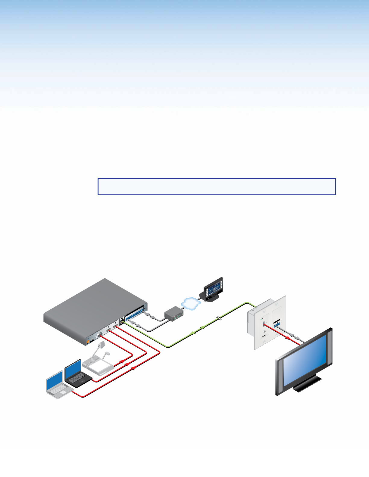
About the DTP T USW 333 Switcher
The DTP T USW 333 is a 3 input VGA and HDMI switcher with a DTP transmitter output
(see figure 1). It switches among one analog VGA and two HDMI inputs, including embedded
audio (or DVI video with the appropriate adapters). The switcher converts the selected input,
an optional analog audio input, and bidirectional RS-232 and infrared (IR) control signals
to a proprietary digital signal. It outputs the signal to a compatible DTP DVI 330 Rx or
DTP HDMI 330 Rx receiver. The switcher and receiver extend the usable distance of video,
audio, and control signals up to 330 feet (100 m) over a single twisted pair cable.
ron
USW 333
P Transmitter
RESET
Switcher
Rx
Control
x
T
ptop
Laptop
POWER
12V
--A MAX
Document
Camera
1
AUDIO
RGB, Y, R-Y, B-Y HDMI HDMI
INPUTS
CONTACT RS-232TALLY
OVER DTP REMOTE
RS-232 IR
1 2 3 G 1 2 3 +V
SIG LINK
Rx GTx RxTxG
3
DTP OUT
2
AV Device
Control
VGA
NPUT
I
IR
3
1
M
31
CO
4
TX RX
2
IPL 250
1
42
2
R
3
TCP/IP
®
100
AY
EL
INK
R
L
Extron
ACT
3
1
4
2
IPL 250
VCR
VD
D
DOC
CAM
TOP
LAP
PC
ON
OFF
PLAY
S
I
E
D
UT
M
N
E
RE
C
S
P
U
EN
RE
SC
OWN
D
CATx Cable
Up to 330' (100 m)
TouchLink
Control
System
OUTPUTS
AUDIO
Extron
DTP HDMI 330 D Rx
Receiver
IR
OVER DTP
RS-232
TxRx G Tx Rx
HDMI with
Embedded
Audio
AV Device
Control
HDMI
Flat Panel Displa
with Speakers
Figure 1. Typical Switching Transmitter Application
The DTP T USW 333 is housed in a half rack width metal enclosure. It can be set on a
tabletop or mounted in a rack, or under or through furniture.
The included external desktop 12 VDC power supply accepts 100 to 240 VAC, 50-60 Hz. A
single power supply connected to either unit can power both units through the TP cable.
DTP T USW 333 • Introduction 1
Page 7

Features
TP Cable
Extron recommends XTP DTP 24 shielded twisted pair (STP) cable for best performance.
Category (CAT) 5e, CAT 6, CAT 6a, or CAT 7 STP or unshielded twisted pair (UTP) cable
is acceptable. Extron recommends at least 24 AWG, solid conductor, STP cable with a
minimum bandwidth of 400 MHz.
NOTE: Do not use Extron UTP23SF-4 Enhanced Skew-Free AV UTP cable or
STP201 cable to link the switching transmitter and receiver. The DTP T USW 333 does
not work properly with these cables.
Twisted pair cable is smaller, lighter, more flexible, and less expensive than coaxial
cable. The DTP 330-enabled products make cable runs simpler and less cumbersome.
Termination of the cable with RJ-45 connectors is simple, quick, and economical.
Control Communications
The RS-232 and IR communications are pass-through only. The switching transmitter and
receiver do not generate or respond to the RS-232 and IR communication signals.
Transmits HDMI or analog video, control, and analog audio up to 330 feet
(100 meters) over a single CATx cable — The DTP T USW 333 provides high reliability
and maximum performance on an economical and easily installed cable infrastructure.
Inputs — Two HDMI, one RGBHV or component video on 15-pin HD, one 3.5 mm stereo
mini jack for audio
Supports computer video to 1920x1200, including HDTV 1080p/60 Deep Color and 2K —
The DTP T USW 333 supports digital signal transmission up to 330 feet over a single
twisted pair cable and maintains superior image quality at the highest resolutions.
Accepts additional analog stereo audio signals — The DTP T USW 333 accepts a
direct analog audio connection from Blu-ray Disc players, laptops, or other devices with
stereo output and digitizes them for simultaneous transmission over the same single twisted
pair cable. A DTP 330 receiver can output balanced and unbalanced audio, allowing
streamlined integration within an AV system.
Bidirectional RS-232 and IR insertion for AV device control — Control and IR signals
can be transmitted alongside the video signal over DTP connections, allowing the remote
device to be controlled without the need for additional cabling. Bidirectional control insertion
eliminates the need for control system wiring to remote devices.
Remote powering of transmitter or receiver — For simplified installation, only one
power supply is necessary to power both devices.
Digital conversion of analog input signals — Analog signals are digitized, ensuring that
a reliable, high quality digital video signal is sent to the output destination.
EDID Minder — Automatically manages EDID communication between connected devices,
ensuring that all sources power up properly and reliably output content for display.
Key Minder — Authenticates and maintains continuous HDCP encryption between input
and output devices, verifying HDCP compliance for quick, reliable switching in professional
AV environments.
Compatible with all DTP HDMI 330 and DTP DVI 330 receivers, and
DTP 330-enabled products — Enables mixing and matching with desktop and wallplate
receivers, as well as other DTP 330-enabled products to meet application requirements.
DTP T USW 333 • Introduction 2
Page 8
Installation and
POWER
12V
2
--A MAX
Rx GTx RxTxG
RS-232 IR
RxTx
1
RGB, Y, R-Y, B-Y HDMI HDMI
SIG LINK
DTP OUT
AUDIO
CONTACT RS-232TALLY
3
123G 123+V
RESET
INPUTS
OVER DTP REMOTE
4 6 7 8
10 3 2 2 951
RGB, Y, R-Y, B-Y
HDMI
Operation
This section describes the installation and the operation of the DTP T USW 333, including:
• Mounting the Unit
• Connections and Reset Button
• Operation
Mounting the Unit
Mounting instructions can be found in Mounting the Switcher on page 18. Compatible
optional hardware is listed on the Extron website (www.extron.com).
ATTENTION:
• Installation and service must be performed by authorized personnel only.
• Avoid ground potential differences between the switching transmitter and receiver
installation sites, which can lead to equipment damage or a missing or unstable
picture. If a potential difference cannot be avoided, remove the ground connection
between the units and locally power both units (see Disconnecting the Ground
on page 19). In this configuration, the DTP T USW 333 cannot extend analog audio
and the paired receiver requires its own dedicated power supply.
Connections and Reset Button
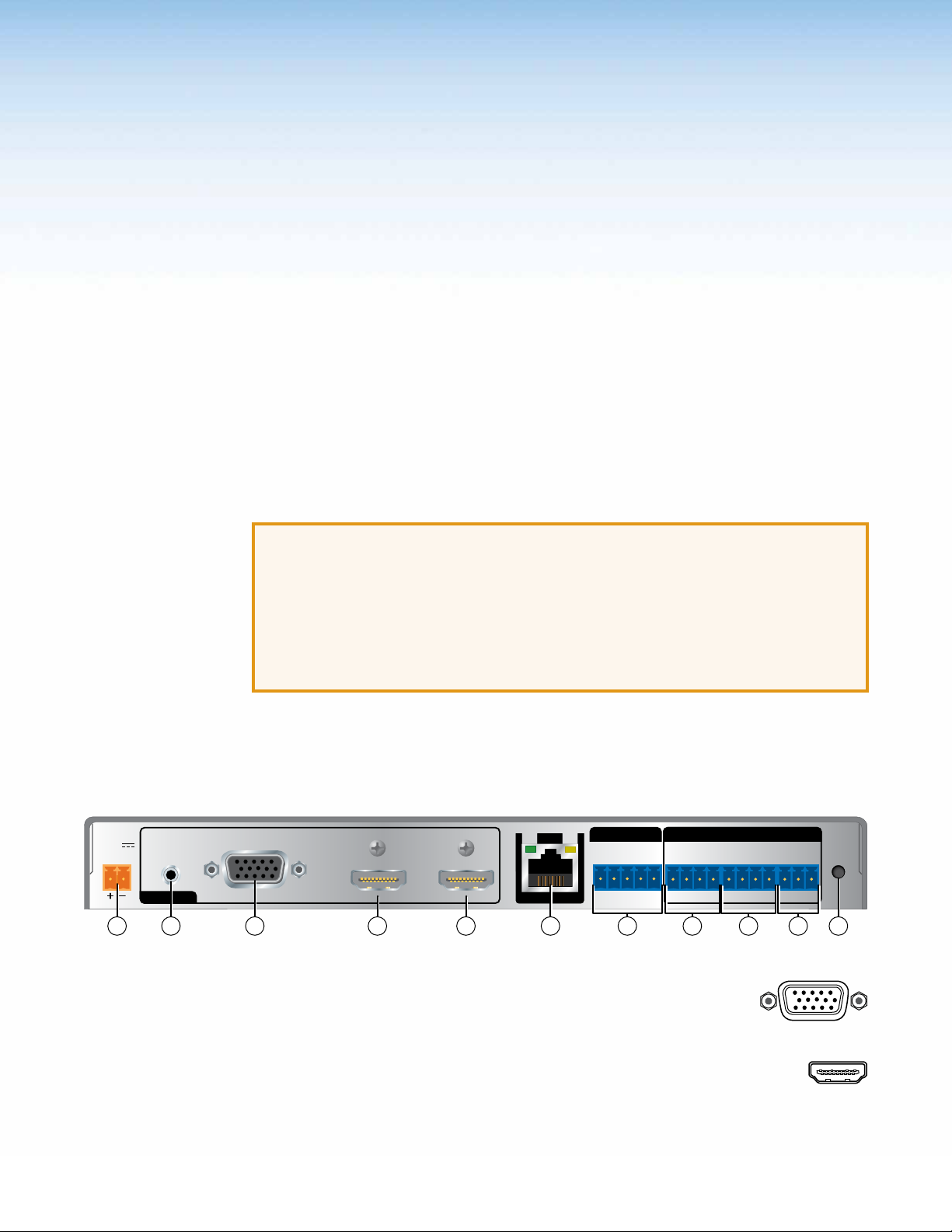
Rear Panel Features
Figure 2. DTP T USW 333 Rear Panel Features
a RGB, Y, R-Y, B-Y input port (input 1) — Plug an analog (RGB
and component) video source into the switching transmitter via this
15-pin HD connector. See VGA connector wiring on page 6 to for
connector pinout.
b HDMI input port (input 2 and 3) — Plug HDMI digital video
sources into the switching transmitter via these HDMI connectors. These
connectors can also accept DVI video with appropriate adapters.
DTP T USW 333 • Installation and Operation 3
Page 9

c Audio input port — If desired, plug an analog audio input into the switching
AUDIO
Sleeve ( )
Ring (-)
Tip (+)
3.5 mm Stereo Plug Connector
(balanced)
RxTx RxTxG
RS-232 IR
SIG LINK
DTP OUT
CONTACT
123G
transmitter via this stereo mini jack connector. Analog audio is not embedded into
the digital video signal.
NOTES:
• The analog audio input on this connector is
in addition to the digital audio that may be
embedded in the HDMI inputs. See the figure
at right to identify the connector tip, ring, and
sleeve when you are making connections for the
switching transmitter from existing audio cables.
A mono audio connector consists of the tip and
sleeve. A stereo audio connector consists of the
tip, ring, and sleeve.
• If you have removed the ground jumpers (see Disconnecting the Ground on
page 19) because of ground potential differences, the DTP T USW 333 cannot
extend analog audio. The connected receiver outputs no analog audio.
• The analog audio can be assigned to a specific input or set to be always
output (see Assign analog audio SIS commands on page 15).
d Over DTP RS-232 and IR port — Plug a serial RS-232 signal, a
modulated IR signal, or both into this 3.5 mm, 5-pole captive screw
connector for bidirectional RS-232 and IR communication (see see IR and
RS-232 connector wiring on page 8 to wire the connector).
e DTP Output RJ-45 port — Plug one end of a TP cable to this
RJ-45 female jack on the switching transmitter. Plug the opposite end of
this cable is into the DTP Input RJ-45 connector on a compatible receiver
(see TP cable termination and recommendations on the next page to
properly wire the RJ-45 connector and for detailed NOTES).
ATTENTION: Do not connect this device to a telecommunications or computer
data network.
Signal LED — Lights when the unit is outputting a TMDS clock signal on the DTP output.
Link LED — Indicates a valid link is established between the units on the DTP cable.
f Remote Contact port — If desired, for contact closure control, plug a
locally-contructed contact closure device into this 3.5 mm, 4-pole captive
screw port. Momentarily short the pin for the desired input (1, 2, or 3) to G to
select that input. To force an input to be always selected, leave the short in
place.
NOTES:
• Contact closure control overrides front panel input selections.
• For contact closure control, auto switch mode must be off (see Selecting the
switch mode on page 11).
DTP T USW 333 • Installation and Operation 4
Page 10

g Remote Tally port — If desired, to remotely identify the currently selected
123
TALLY
+V
GRxTx
RS-232
RESET
Side
Pair Wires
Pins:
input, plug a locally-constructed device into this 3.5 mm, 4-pole captive
screw connector. Connect the power wire for the device into the +V pin and
connect the ground wire for the each indicator into the corresponding tally out pin, 1, 2,
or 3.
When an input is selected, by either contact closure of front panel selection, the
corresponding tally out pin shorts to ground, closing the circuit and lighting the
connected indicator (LED).
h Remote RS-232 port — Plug a serial RS-232 device into the switching
transmitter via this 3.5 mm, 3-pole captive screw connector for remote control
of the switching transmitter (see IR and RS-232 connector wiring on page 8
to wire the connector).
i Reset button — The Reset button initiates two levels of reset of the switcher.
For the different reset levels, press and hold the button while the switcher is
running or while you power up the switcher (see Reset on page 11 for details).
j Power connector — Plug the included external 12 VDC power supply into either
this 2-pole connector (see Power supply wiring on page 7 to wire the connector) or
the power input connector on the receiver (see the DTP HDMI 330 User Guide on the
Extron website (www.extron.com).
NOTES:
• The power supply included with the switching transmitter can normally power
both units.
• If you have removed the ground jumpers (see Disconnecting the Ground on
page 19) because of ground potential differences, one unit of the pair cannot
remotely power the other unit. Each unit requires a local power supply.
Connector and Cable Details
TP cable termination and recommendations
Figure 3 details the TIA/EIA T 568B wiring standard. Use this standard to terminate the
DTP cable with RJ-45 connectors.
12345678
Insert
Twisted
Figure 3. TP Cable Termination
NOTE: Do not use Extron UTP23SF-4 Enhanced Skew-Free AV UTP cable or STP201
cable to link the switching transmitter and receiver. The DTP T USW 333 Tx/Rx does
not work properly with these cables.
RJ-45
Connector
TIA/EIA T
568B
Pin
Wire color
White-orange
1
Orange
2
3
White-green
4
Blue
5
White-blue
6
Green
7
White-brown
8
Brown
DTP T USW 333 • Installation and Operation 5
Page 11

Supported cables
Pin RGBHV
1
Red
Green
R-Y
Y
Red return R-Y return
Green return Y return
Blue return B-Y return
NC NC
Blue B-Y
RGBS Component
2
Red
Green
NC
6 Red return
7 Green return
8 Blue return
3 Blue
15
11
15
4, 5
Pin RGBHV RGBS Component
9
10
14
15
11
12
13
NC
Ground
V sync
NC
H sync
NC
Ground
NC
NC
NC NC
C sync
NC NC
NC
NC
NC
NC
NC
NC
NC
The DTP T USW 333 is compatible with CAT 5e, 6, 6a, and 7 shielded twisted pair (F/UTP,
SF/UTP, and S/FTP) and unshielded twisted pair (U/UTP) cable.
Cable recommendations
Extron recommends using the following practices to achieve full transmission distances up
to 330 feet (100 m) and reduce transmission errors.
• Use the following Extron XTP DTP 24 SF/UTP cables and DTP 24 connectors for the
best performance:
• XTP DTP 24/1000 Non-Plenum 1000’ (305 m) spool 22-236-03
• XTP DTP 24P/1000 Plenum 1000’ (305 m) spool 22-235-03
• XTP DTP 24 Plug Package of 10 101-005-02
• If not using XTP DTP 24 cable, at a minimum, Extron recommends 24 AWG, solid
conductor, STP cable with a minimum bandwidth of 400 MHz.
• Terminate cables with shielded connectors to the TIA/EIA T 568 B standard.
• Use no more than two pass-through points, which may include patch points, punch
down connectors, couplers, and power injectors. If these pass-through points are
required, use CAT 6 or 6a shielded couplers and punch down connectors.
NOTE: When using TP cable in bundles or conduits, consider the following:
• Do not exceed 40% fill capacity in conduits.
• Do not comb the cable for the first 20 meters, where cables are straightened,
aligned, and secured in tight bundles.
• Loosely place cables and limit the use of tie wraps or Velcro®.
• Separate twisted pair cables from AC power cables.
VGA connector wiring
The 15-pin HD (VGA) universal analog input ports accept RGB (RGBHV, RGBS, RGsB) and
component video. Figure 4 shows the pinouts for each format type on the connector.
Figure 4. VGA Connector
DTP T USW 333 • Installation and Operation 6
Page 12

Power supply wiring
Power Supply
Output Cord
SECTION A–A
Ridges
Smooth
AA
Tie Wrap
3
5
NOTES:
• The power supply included with the switching transmitter can normally power both
units.
• If you have removed the ground jumpers (see Disconnecting the Ground on
page 19) because of ground potential differences, one unit of the pair cannot
remotely power the other unit. Each unit requires a local power supply.
Figure 5 shows how to wire the connector. Use the supplied tie-wrap to strap the power
cord to the extended tail of the connector.
Figure 5. Power Connector Wiring
CAUTION: Electric shock hazard —
• The two power cord wires must be kept separate while the power supply is
plugged in. Remove power before wiring.
• The length of exposed wires is critical. The ideal length is 3/16 inch (5 mm).
• If the stripped section of wire is longer than 3/16 inch, the exposed wires may
touch, causing a short circuit.
• If the stripped section of wire is shorter than 3/16 inch, wires can be easily pulled
out even if tightly fastened by the captive screws.
• Do not tin the power supply leads before installing them in the connector. Tinned
wires are not as secure in the connector and could be pulled out.
ATTENTION:
• This product is intended to be supplied by a Listed Power Unit marked “Class 2”
or “LPS,” rated 12 VDC, 1.0 A minimum. Always use a power supply supplied by
or specified by Extron. Use of an unauthorized power supply voids all regulatory
compliance certification and may cause damage to the supply and the end product.
• Unless otherwise stated, the AC/DC adapters are not suitable for use in air handling
spaces or in wall cavities.
• The installation must always be in accordance with the applicable provisions of
National Electrical Code ANSI/NFPA 70, article 75 and the Canadian Electrical
Code part 1, section 16. The power supply shall not be permanently fixed to a
building structure or similar structure.
• Power supply voltage polarity is critical. Incorrect voltage polarity can damage the
power supply and the unit. The ridges on the side of the cord (see figure 5) identify
the power cord negative lead.
To verify the polarity before connection, plug in the power supply with no load and check the
output with a voltmeter.
DTP T USW 333 • Installation and Operation 7
Page 13

IR and RS-232 connector wiring
IR Device
RS-232 Device
Figure 6 shows how to wire the Remote RS-232 and Over DTP RS-232 and IR connectors.
G
RS-232
REMOTE
RxTx
V
OVER DTP
Figure 6. IR and RS-232 Connectors Wiring
NOTES:
• The IR Tx and Rx line pair and the RS-232 Tx and Rx line pairs must each cross
once between their connectors and the source or destination.
• The length and preparation of exposed wires is important (see the second and third
power connector CAUTIONS on the previous page for details).
Front Panel Configuration Port
AUTO
SWITCH
CONFIG
TxRx
Gnd
Rx
RS-232 IR
Tx RxTxG
RxTx
Gnd
1
Figure 7. Front Panel Configuration (Config) Port
a Configuration port — This mini USB B port serves a similar communications function
as the rear panel Remote RS-232 port, but it is easier to access than the rear port after
the switcher has been installed and cabled.
NOTE: A front panel Configuration port connection and a rear panel Remote
RS-232 port connection can both be active at the same time. If commands are
sent simultaneously to both, the command that reaches the processor first is
handled first.
DTP T USW 333 • Installation and Operation 8
Page 14

Operation
Controls and Indications
AUTO
SWITCH
CONFIG
MODE
3
STATUS
1
NORMAL
23
AUTO
SIGNAL
123
HDCP
DTP T USW 333
1 4 5 6
2
7
Figure 8. Power Indicators
Auto Switch mode indicator
a Auto Switch LED — When lit, indicates that the switcher is in auto-input switching
mode. When unlit, the switch is in normal (manual) mode (see Selecting the switch
mode on page 11).
Input selection controls and indicators
b Input 1 through 3 buttons — Each Input button selects the associated input for
output (see Switching inputs on the next page).
The Input buttons are also used to toggle auto-input switching mode on and off (see
“Auto-input switching mode controls,” below).
c Input 1 through 3 LEDs — The input LEDs identify the selected input.
Auto-input switching mode controls
The switcher supports auto-input switching mode. When auto-input switching mode is
enabled, the switcher continuously monitors all inputs and automatically switches to the
highest-numbered input with video sync pulses present. If video is absent from all inputs,
input 1 is selected.
d Mode button — The Mode button is used with the Normal button or the Auto button
to select the switching mode (see Selecting the switch mode on page 11).
This button is a secondary function of the Input 1 button.
e Normal button — The Normal button is used with the Mode button to select normal
mode (see Selecting the switch mode on page 11).
This button is a secondary function of the Input 2 button.
When you change from auto-input switching to normal (manual) mode, the last input
selected in auto-input switching mode remains selected until you manually select a
different input.
f Auto(switch) button — The Auto button is used with the Mode button to select auto-
input switchinging mode (see Selecting the switch mode on page 11).
This button is a secondary function of the Input 3 button.
DTP T USW 333 • Installation and Operation 9
Page 15

Status LEDs
23
MODE
NORMAL
AUTO
Press the button.
The LED lights
g Status LEDs —
Signal LEDs (1 through 3) — Indicates that the switcher detects Horizontal sync
(Signal LED 1) or TMDS clock (Signal LED 2 and Signal LED 3) on the associated input.
HDCP LEDs (2 and 3) — Indicates that the input signal is HDCP encrypted.
Front Panel Operations
The following paragraphs detail the power up process and provide sample procedures for
switching inputs, changing between normal and auto-input switching mode, and toggling
executive mode on and off.
Power
Power is automatically applied when the power cord is connected to an AC source. When
AC power is applied, the switcher performs a self-test that blinks the front panel LEDs
during the test. An error-free power up self-test sequence leaves the Auto Switch and Input
LEDs on or off in the same configuration as they were when power was last removed.
If an error occurs during the self-test, the switcher locks up and will not operate. If your
switcher locks up on power-up, call the Extron S3 Sales & Technical Support Hotline.
Plug in all system components and turn on the input devices (such as Blu-Ray players
and computers) and the output devices. Set the input devices to output video using the
operating instructions of that device. Select an input. The image should appear on the
screen. If no image appears, see Troubleshooting — If No Image Appears on the next
page.
Switching inputs
Select an input for transmission to the receiver using the front panel buttons as follows:
1. Select the desired input by pressing the associated input button (see figure 9).
Figure 9. Selecting an Input
2. Observe that the LED for the selected input lights.
NOTE: The switcher must be in normal (manual) mode.
An input can also be selected using an RS-232 or USB device or a contact closure device
(see Remote Control, beginning on page 12).
green.
1
DTP T USW 333 • Installation and Operation 10
Page 16

Selecting the switch mode
MODE
NORMAL
Press the and HOLD the Mode button.
Release the Mode button.
NOTE: In the auto-input switching mode that is available from the front panel, the
switcher selects to the highest numbered input with a sync signal present. See the
Front panel mode SIS commands on page 15 for an auto-input switching low mode,
which selects the lowest numbered input.
Turn auto-input switching mode on and off as follows:
1. Press and hold the Mode (Input 1) button (see figure 10).
Press and release the Auto or Normal button.
1 23
AUTO
Auto Switch lights (auto)
or goes out (normal).
AUTO
SWITCH
Figure 10. Selecting a Mode
2. Press and release the button for the desired mode
Auto (Input 3) — The Auto Switch LED lights.
Normal (Input 2) — The Auto Switch Active LED goes off.
3. Release the Mode button.
Front panel security lockout (Executive mode)
The switcher has a front panel lock feature that locks the front panel. If you try to make front
panel input selections when the panel is locked, all front panel LEDs flash three times.
Toggle the front panel lock on and off as follows:
1. Push and hold the Input 1, Input 2, and Input 3 buttons simultaneously for 5 seconds.
All front panel LEDs flash three times.
2. Release the buttons.
When the front panel is locked, contact closure and RS-232 control are still available.
Reset
Troubleshooting — If no Image Appears
Use the recessed rear panel Reset button to initiate two levels of reset as follows:
Reset to default settings — Press and hold the reset button for approximately 6
seconds. All front panel LEDs cycle. Release the button. This reset is the equivalent of
issuing the Reset SIS command (EZXXX}).
Reset to factory default condition — Cycle unit power off and on while holding the reset
button. All front panel LEDs cycle. Release the button.
1. Ensure that all devices are plugged in and powered on. The switcher is receiving power
if one of the input LEDs is lit.
2. Ensure an active input is selected on the switcher or that the switcher is in auto-input
switching mode.
3. Ensure that the proper signal format is supplied.
4. Check the cabling and make corrections as necessary.
5. Call the Extron S3 Sales & Technical Support Hotline if necessary.
DTP T USW 333 • Installation and Operation 11
Page 17

Remote Control
This section includes:
• Contact Closure Control
• Simple Instruction Set Control
The DTP T USW 333 switcher can be remotely controlled via its rear panel Remote RS-232
port, its front panel configuration (USB) port, and its rear panel Remote Contact port.
Remote control devices can be:
• A host device such as a computer or control system and the Extron Simple Instruction
Set
• A contact closure device such as an Extron KP 6 Keypad Control or a Show Me video
cable
Contact Closure Control
The rear panel Remote Contact port (see item f on page 4) provides a way to select
an input to the switcher using a remote contact closure device. The contact closure pin
assignments are shown on page 4.
NOTE: The switcher must be in normal (manual) mode.
To select a different input number using a contact closure device, momentarily short the pin
for the desired input number to ground. To force one of the inputs to be always selected,
leave the short to ground in place. The short overrides front panel input selections.
DTP T USW 333 • Remote Control 12
Page 18

Simple Instruction Set Control
The DTP T USW 333 switching transmitter can be remotely controlled using SIS commands
from a host device such as a computer or control system via its rear panel Remote RS-232
port (see item h on page 5) or front panel Configuration (USB) port (see item a on
page 8).
The default serial port protocol of the port is as follows:
• 9600 baud • No parity • 8-bit
• No flow control • 1 stop bit
Host-to-Switcher Communications
SIS commands consist of one or more characters per field. No special characters are
required to begin or end a command character sequence. When a command is valid, the
switcher executes the command and sends a response to the host device. All responses
from the switcher to the host end with a carriage return and a line feed (CR/LF = ]), which
signals the end of the response character string. A string is one or more characters.
Switcher-Initiated Messages
When a local event occurs, such as a front panel operation, loss or restoration of an input
signal, or an error condition, the switcher responds by sending a message to the host. The
switcher-initiated messages are listed below:
© Copyright 20yy, Extron Electronics DTP T USW 333, Vx.xx, 60-nnnn-nn
The switcher issues the copyright message when it first powers on. Vx.xx is the firmware
version number and 60-nnnn-nn is the part number.
Inn All
]
The switcher also sends the Inn message whenever the selected input is changed. n is the
input number. A 0 in the n field indicates no input is selected.
]
Error responses
When the switcher receives a valid SIS command, it executes the command and sends a
response to the host device. If the switcher is unable to execute the command because the
command is invalid or it contains invalid parameters, the switcher returns an error response
to the host. The error response codes are:
E01 — Invalid input channel number (out of range)
E06 — Invalid channel change
E10 — Invalid command
E13 — Invalid parameter
Timeout
Pauses of 10 seconds or longer between command ASCII characters result in a timeout.
The command operation is aborted with no other indication.
DTP T USW 333 • Remote Control 13
Page 19

Using the Command and Response Table
ASCII to Hex Conversion Table
Space
The command and response table begins on the next page. Symbols are used
throughout the table to represent variables in the command and response fields. Command
and response examples are shown throughout the table. The ASCII to HEX conversion table
below is for use with the command and response table.
•
Symbol definitions
= Carriage return/line feed
]
= Carriage return (no line feed)
}
| = Pipe (can be used interchangeably with the } character)
• = space
= Escape key
E
W = Can be used interchangeably with the E character
X! = Input number 0
X@ = Switch mode 0 = Manual (default) 2 = Auto-input switching low
or 1 through 3 (0 = no input for switching command or always output for audio
assignment)
1 = Auto-input switching high
X# = Status 0 = Off, disabled, or not detected 1 = on, enable, or detected
X$ = HDMI input 2 or 3
X% = Input HDCP status 0 = No source is detected
1 = Source is detected with HDCP
2 = Source detected without HDCP
X^ = Output HDCP status 0 = No sink is detected
1 = Sink is detected with HDCP
2 = Sink is detected without HDCP
X& = EDID See table 1 on page 16.
X* = User EDID location 66, 67, or 68
X( = Raw EDID data 128 or 256 bytes of hexadecimal data
X1) = Resolution and rate in plain text Example: 1920x1200•@60Hz
X1! = Analog input video format 0 = Auto detect (default) 1 = RGB (VGA) 2 = YUV/component video
X1@ = Switcher name A text string of up to 24 alphanumeric characters and minus sign/hyphen (-).
No blank or space characters are permitted as part of a name. The first letter must a
letter, and the last character must not be a minus sign/hyphen.
X1# = Firmware version number to second decimal place (x.xx)
X1$ = Verbose mode 0 = clear/none (default) 2 = tagged responses for queries
1 = verbose mode (default for RS-232 or USB) 3 = verbose mode and tagged for queries
DTP T USW 333 • Remote Control 14
Page 20

Command and Response Table for SIS Commands
Command Function
SIS Command
(Host to Unit)
Response
(Unit to Host)
Additional description
Select and view input
Select an input
Example:
View input selection
X!
! InX!•All
1!
!
In01•All
X!]
Front panel mode
Set normal switch mode
Set auto switch mode high
Set auto switch mode low
View front panel switch mode
E
E
E
E
}
0AUSW
}
1AUSW
}
2AUSW
} X@]
AUSW
Ausw0
Ausw1
Ausw2
Assign analog audio input to specific video input or always output audio
Always output analog audio
Assign (lock) analog audio to a
specific input
View audio assignment
E
EX!
E
}
0AFLW
}
AFLW
} X!]
AFLW
Aflw0
Aflw
Input signal status
Request status of all inputs and the
output
E
0LS
}
Sig
HDCP Status
View the HDCP status of an HDMI
input
View the HDCP status of both HDMI
inputs
View the output HDCP status
EIX!
E
IHDCP
E
OHDCP
HDCP
}
}
}
HdcpI
HdcpI
HdcpO
HDCP Authorized Device
Set HDMI input to HDCP authorized
Set HDMI input to HDCP not
authorized
Set HDCP authorization, both HDMI
inputs
View HDCP authorized status
EEX$
EEX$
EEX#
E
EHDCP
}
*1HDCP
}
*0HDCP
}
HDCP
} X#
HdcpEX$*1
HdcpEX$*0
HdcpE
Front panel security lockout (executive mode)
Lock front panel
Unlock front panel
Read lock status
1X
0X
X
Exe1
Exe0
X#]
•
2
X#3]
•
]
]
]
]
X!]
1
X#
X%]
X%
X^]
X#]
]
]
X#
•
2
]
]
2
X%3]
•
]
]
Select input X! to transmit to the
connected receiver.
Select input 1.
Input X! is selected.
Set switch mode to normal. Default.
Set switch mode to auto (high). The
switcher automatically selects the
highest-numbered input with a signal
present.
Set switch mode to auto (low). The
switcher automatically selects the
lowest-numbered input with a signal
present.
Analog audio is output regardless of
input selection. Default.
Assign analog audio to input X!.
3
X#
X#o]
•
*
1
X#
through
of inputs 1 through 3.
signal status.
Default.
Status of input 2 and input 3.
Set lock on.
Set lock off. Default.
Lock status = X#.
3
X#
are the signal status
o
X#
is the output
NOTE: X! = Input number 0
X@
= Switch mode 0 = Manual (default) 1 = Auto-input switching high 2 = Auto-input switching low
X#
= Status 0 = Not detected, authorized 1 = Detected, authorized
X$
= HDMI input 2 or 3
X%
= Input HDCP status 0 = No source detected 2 = Source detected without HDCP 1 = Source detected with HDCP
X^
= Output HDCP status 0 = No sink detected 1 = Sink detected with HDCP 2 = Sink detected without HDCP
or 1 through 3 (0 = no input for switching command or always output for audio assignment)
DTP T USW 333 • Remote Control 15
Page 21

Command Function
SIS Command
(Host to Unit)
EDID Minder
NOTE: See table 1, below for the EDID values.
Response
(Unit to Host)
Additional description
Assign EDID to an input
Save the EDID of the connected
display to a user location
View the EDID assignment
View raw EDID data
View EDID native resolution
EAX!*X&
ESX*
EDID
EAX!
EDID
ERX!
EDID
ENX!
EDID
}
EDID
}
EdidAX!*
EdidS
} X&]
} X(]
} X1)]
X*]
X&]
Defaults: 03 and 50.
Save EDID of display connected to the
output to the user store slot 66, 67, or 68.
Read data as text from the EDID
assigned and used on input
Read out native resolution and refresh
rate from the EDID assigned to the
specified input in plain text.
Example:
1920x1200 @60Hz
X!
.
Table 1. EDID Values
X&
Value
VGA – PC values
800x600 @ 60 Hz
01
1024x768 @ 60 Hz
02
1280x720 @ 60 Hz
03*
1280x768 @ 60 Hz
04
DVI – PC values
800x600 @ 60 Hz 21 1280x800 @ 60 Hz
17
1024x768 @ 60 Hz 22 1280x1024 @ 60 Hz
18
1280x720 @ 60 Hz 23 1360x768 @ 60 Hz
19
1280x768 @ 60 Hz 24 1366x768 @ 60 Hz
20
HDMI – PC values, with 2-channel audio
800x600 @ 60 Hz
33
1024x768 @ 60 Hz
34
1280x768 @ 60 Hz
35
1280x800 @ 60 Hz
36
HDMI – HDTV values, with 2-channel audio
47
48
49
480p @ 60 Hz
576p @ 50 Hz
720p @ 50 Hz
HDMI – HDTV values, with multi-channel audio
57
58
720p @ 50 Hz
720p @ 60 Hz
Output and user locations
X&
65
* Default for input 1.
✝ Default for inputs 2 and 3.
Source
Output
X&
1280x800 @ 60 Hz
05
1280x1024 @ 60 Hz
06
1360x768 @ 60 Hz
07
1366x768 @ 60 Hz
08
1280x1024 @ 60 Hz
37
1360x768 @ 60 Hz
38
1366x768 @ 60 Hz
39
1400x1050 @ 60 Hz
40
✝
50
51
52
59
60
720p @ 60 Hz
1080i @ 50 Hz
1080i @ 60 Hz
1080i @ 50 Hz
1080i @ 60 Hz
X&
66
User location 1
Value
Source
X&
1400x1050 @ 60 Hz
09
1440x900 @ 60 Hz
10
1600x900 @ 60 Hz
11
1600x1200 @ 60 Hz
12
1400x1050 @ 60 Hz
25
1440x900 @ 60 Hz
26
1600x900 @ 60 Hz
27
16001200 @ 60 Hz
28
1440x900 @ 60 Hz
41
1600x900 @ 60 Hz
42
1600x1200 @ 60 Hz
43
1680x1050 @ 60 Hz
44
1080p @ 50/25 Hz
53
54
55
61
62
1080p @ 50 Hz
1080p @ 60/24 Hz
1080p @ 50/25 Hz
1080p @ 50 Hz
X&
67
User location 2
Value
Source
X&
1680x1050 @ 60 Hz
13
1920x1080 @ 60 Hz
14
1920x1200 @ 60 Hz
15
2048x1080 @ 60 Hz
16
1680x1050 @ 60 Hz
29
1920x1080 @ 60 Hz
30
1920x1200 @ 60 Hz
31
2048x1080 @ 60 Hz
32
1920x1200 @ 60 Hz
45
2048x1080 @ 60 Hz
46
56
63
64
1080p @ 60 Hz
1080p @ 60/24 Hz
1080p @ 60 Hz
X&
68
User location 3
Value
Source
NOTE: X! = Input number 1
X& = EDID See table 1, above.
X* = User EDID location 66, 67, or 68
X( = Raw EDID data 128 or 256 bytes of hexadecimal data
X1) = Resolution and rate in plain text Example: 1920x1200•@60Hz
through 3
DTP T USW 333 • Remote Control 16
Page 22

Command Function
SIS Command
(Host to Unit)
Response
(Unit to Host)
Additional description
Input 1 (only) video format
Set format
Example:
View format
View detected format
X1!
1*
\ Typ
1*0\
1\
1*\
X1!]
Typ0
X1!]
X1!]
]
Set input 1 to format
Set input 1 to autodetect.
View set format.
View detected format (
X1!
X1!
.
= 1 or 2 only).
Video mute
Mute video
Unmute video
Read video mute
1B
0B
B
Vmt1
Vmt0
X#]
]
]
Output no video signal.
Output selected video input.
Mute status = X#.
Analog audio mute
Mute analog audio
Unmute analog audio
Read analog audio mute
1Z
0Z
Z
Amt1
Amt0
X#]
]
]
Output no analog audio signal.
Output analog audio input.
Analog audio mute status = X#.
Disable (Mute) HDMI Output Embedded Audio
Enable HDMI audio output
Disable HDMI audio output
View HDMI audio configuration
E
E
E
}
1AFMT
}
0AFMT
} X#]
AFMT
Afmt1
Afmt0
]
]
Enable HDMI audio. (Default)
Disable HDMI audio.
Device Name
Set the unit name
Set unit name to factory default
View unit name
EX1@CN}
E
}
•
CN
ECN} X1@]
X1@]
Ipn
•
Ipn•DTP-T-USW-333
Change the name to one of your choosing.
]
Set name to default.
Reset
Reset to factory setting
Reset to factory setting and device
name
E
ZXXX
ZQQQ
}
}
Zpx
Zpq
]
]
Reset to factory defaults.
Reset to factory defaults, including,
default name (
DTP-T-USW-333).
E
Information requests
X!
Information request
Example:
Request part number
Query controller firmware version
Example:
I
I
N
Q
Q
In
In1
60-nnnn-nn
X1#]
1.23
X!
•
Aflw
•
Aflw2•Ausw1•Vmt1•Amt0
]
•
]
Ausw
X@
X#
•
Amt
X#]
•
Vmt
]
Input 1 is selected, analog audio is
assigned to input 2, the switcher is in
auto-input switching (high) mode, video
is muted and analog audio is unmuted.
See the Extron website,
www.extron.com, for part numbers.
The factory-installed controller firmware
version is 1.23 (sample value only).
Verbose mode
NOTE: If tagged responses are enabled (modes 2 and 3), all “view” commands return the prefix and the value, just as the “set”
commands do. For example, the View front panel switch mode (
Set verbose mode
Read verbose mode
NOTE: X! = Input number 0
X@
= Switch mode 0 = Manual (default) 1 = Auto-input switching high 2 = Auto-input switching low
X#
= Status 0 = Off, disabled, or not detected 1 = on, enable, or detected
X1!
= Analog input video format 0 = Auto detect (default) 1 = RGB (VGA) 2 = YUV/component video
X1@
= Switcher name A text string of up to 24 alphanumeric characters and minus sign/hyphen (-).
X1#
= Firmware version number to second decimal place (x.xx)
X1$
= Verbose mode 0 = clear/none (default) 2 = tagged responses for queries
1 = verbose mode (default for RS-232 or USB) 3 = verbose mode and tagged for queries
EX1$CV}
ECV} X1$]
or 1 through 3 (0 = always output for audio assignment)
E
AUSW
Vrb
}
) command returns “Ausw
X1$]
X@]
“.
DTP T USW 333 • Remote Control 17
Page 23

Reference Information
This section provides procedures for mounting the DTP T USW 333 switching transmitter
and disconnecting the ground between it and a compatible receiver.
• Mounting the Switcher
• Disconnecting the Ground
Mounting the Switcher
ATTENTION:
• Installation and service must be performed by authorized personnel only.
• Avoid ground potential differences between the switching transmitter and receiver
installation sites, which can lead to equipment damage or a missing or unstable
picture. If a potential difference cannot be avoided, remove the ground connection
between the units and locally power both units (see Disconnecting the Ground
on the next page).
The 1-inch high, half rack width DTP T USW 333 switching transmitter can be placed on a
table, mounted in a rack, or mounted under a desk or table.
Tabletop Use
Affix the included rubber feet to the bottom of the unit and place it in any convenient
location.
Mounting kits
Mount the unit using any optional compatible mounting kit listed on the Extron website
(www.extron.com), in accordance with the directions included with the kit. For rack
mounting, see UL Rack-Mounting Guidelines on the next page.
DTP T USW 333 • Reference Information 18
Page 24

UL Rack-Mounting Guidelines
Remove 9 Screws
The following Underwriters Laboratories (UL) requirements pertain to the installation of the
unit into a rack.
• Elevated operating ambient temperature — If installed in a closed or multi-unit rack
assembly, the operating ambient temperature of the rack environment may be greater
than room ambient. Therefore, consider installing the equipment in an environment
compatible with the maximum ambient temperature (TMA = +122 °F, +50 °C) specified
by Extron.
• Reduced air flow — Installation of the equipment in a rack should be such that the
amount of air flow required for safe operation of the equipment is not compromised.
• Mechanical loading — Mounting of the equipment in the rack should be such that a
hazardous condition is not achieved due to uneven mechanical loading.
• Circuit overloading — Consideration should be given to the connection of the
equipment to the supply circuit and the effect that overloading of the circuits might have
on overcurrent protection and supply wiring. Appropriate consideration of equipment
nameplate ratings should be used when addressing this concern.
• Reliable earthing (grounding) — Reliable earthing of rack-mounted equipment
should be maintained. Particular attention should be given to supply connections other
than direct connections to the branch circuit (such as use of power strips).
Disconnecting the Ground
If you cannot resolve a ground potential difference between the switching transmitter and
receiver installation sites (as suggested by a missing or unstable picture), remove the ground
connection between the units as follows:
NOTE: Once you have removed the ground jumpers, the DTP T USW 333 cannot
extend analog audio and one unit cannot remotely power the other. No analog audio
is output and the paired receiver requires its own dedicated power supply.
1. Disconnect any cables and remove the switching transmitter from any rack or other
installation option.
2. Remove and retain the screws (nine screws, three on each side and three on top)
securing the cover to the switching transmitter. Slide the cover forward slightly and lift it
off the unit (see figure 11).
TIP: Be careful not to bend the electrical contact “legs” of the button and LED
assemblies on the circuit board. If the buttons or LEDs are misaligned with the
holes in the cover, it may be difficult to reassemble the switcher.
Figure 11. Opening the Switching Transmitter
DTP T USW 333 • Reference Information 19
Page 25

3. Locate and lift off jumpers JMP1 and JMP2 (see figure 12).
P1
JMP2
JM
Figure 12. Jumper Locations
4. Reinstall the switcher cover, securing it in place with the screws removed in step 2.
5. Reinstall the switcher in the rack or other installation option (see Mounting the
Switcher on page 18).
6. If you are using shielded cable, disconnect the cable shield from the connector at
either end of the cable.
7. See the manual for the applicable receiver, DTP DVI 330 Rx or DTP HDMI 330 Rx,
available on the Extron website (www.extron.com), and remove the ground jumpers in
the receiver.
8. Obtain a second 12 V power supply (one supply is provided with the switching
transmitter and normally powers both units), and locally power both units (see Power
supply wiring on page 7).
DTP T USW 333 • Reference Information 20
Page 26

Extron Warranty
Extron Electronics warrants this product against defects in materials and workmanship for a period of three years
from the date of purchase. In the event of malfunction during the warranty period attributable directly to faulty
workmanship and/or materials, Extron Electronics will, at its option, repair or replace said products or components,
to whatever extent it shall deem necessary to restore said product to proper operating condition, provided that it is
returned within the warranty period, with proof of purchase and description of malfunction to:
USA, Canada, South America,
and Central America:
Extron Electronics
1230 South Lewis Street
Anaheim, CA 92805
Japan:
Extron Electronics, Japan
Kyodo Building, 16 Ichibancho
Chiyoda-ku, Tokyo 102-0082
Japan
U.S.A.
Europe and Africa:
Extron Europe
Hanzeboulevard 10
3825 PH Amersfoort
The Netherlands
China:
Extron China
686 Ronghua Road
Songjiang District
Shanghai 201611
China
Asia:
Extron Asia Pte Ltd
135 Joo Seng Road, #04-01
PM Industrial Bldg.
Singapore 368363
Middle East:
Extron Middle East
Dubai Airport Free Zone
F12, PO Box 293666
United Arab Emirates, Dubai
Singapore
This Limited Warranty does not apply if the fault has been caused by misuse, improper handling care, electrical
or mechanical abuse, abnormal operating conditions, or if modifications were made to the product that were not
authorized by Extron.
NOTE: If a product is defective, please call Extron and ask for an Application Engineer to receive an RA (Return
Authorization) number. This will begin the repair process.
USA: 714.491.1500 or 800.633.9876 Europe: 31.33.453.4040
Asia: 65.6383.4400 Japan: 81.3.3511.7655
Units must be returned insured, with shipping charges prepaid. If not insured, you assume the risk of loss or damage
during shipment. Returned units must include the serial number and a description of the problem, as well as the
name of the person to contact in case there are any questions.
Extron Electronics makes no further warranties either expressed or implied with respect to the product and its quality,
performance, merchantability, or fitness for any particular use. In no event will Extron Electronics be liable for direct,
indirect, or consequential damages resulting from any defect in this product even if Extron Electronics has been
advised of such damage.
Please note that laws vary from state to state and country to country, and that some provisions of this warranty may
not apply to you.
Extron Headquarters
+1.800.633.9876 (Inside USA/Canada Only)
Extron USA - West Extron USA - East
+1.714.491.1500 +1.919.850.1000
+1.714.491.1517 FAX +1.919.850.1001 FAX
Extron Europe
+800.3987.6673
(Inside Europe Only)
+31.33.453.4040
+31.33.453.4050 FAX
© 2014 Extron Electronics All rights reserved. www.extron.com
Extron Asia
+65.6383.4400
+65.6383.4664 FAX
Extron Japan
+81.3.3511.7655
+81.3.3511.7656 FAX
Extron China
+86.21.3760.1568
+86.21.3760.1566 FAX
Extron Middle East
+971.4.299.1800
+971.4.299.1880 FAX
Extron Korea
+82.2.3444.1571
+82.2.3444.1575 FAX
Extron India
1800.3070.3777
(Inside India Only)
+91.80.3055.3777
+91.80.3055.3737 FAX
 Loading...