

Page 1
User Guide
DTP HD DA4 4K 230/330
DTP HD DA8 4K 230/330
DTP HDMI Distribution Amplifiers
Video Products
68-2545-01 Rev. A
02 15
Page 2
Safety Instructions
Safety Instructions • English
WARNING: This symbol, , when used on the product, is intended to
alert the user of the presence of uninsulated dangerous voltage within the
product’s enclosure that may present a risk of electric shock.
ATTENTION: This symbol, , when used on the product, is intended
to alert the user of important operating and maintenance (servicing)
instructions in the literature provided with the equipment.
For information on safety guidelines, regulatory compliances, EMI/EMF
compatibility, accessibility, and related topics, see the Extron Safety and
Regulatory Compliance Guide, part number 68-290-01, on the Extron website,
www.extron.com.
Instructions de sécurité • Français
AVERTISSEMENT: Ce pictogramme, , lorsqu’il est utilisé sur le
produit, signale à l’utilisateur la présence à l’intérieur du boîtier du produit
d’une tension électrique dangereuse susceptible de provoquer un choc
électrique.
ATTENTION: Ce pictogramme, , lorsqu’il est utilisé sur le produit, signale
à l’utilisateur des instructions d’utilisation ou de maintenance importantes
qui se trouvent dans la documentation fournie avec le matériel.
Pour en savoir plus sur les règles de sécurité, la conformité à la réglementation,
la compatibilité EMI/EMF, l’accessibilité, et autres sujets connexes, lisez les
informations de sécurité et de conformité Extron, réf. 68-290-01, sur le site
Extron, www.extron.com.
Sicherheitsanweisungen • Deutsch
WARNUNG: Dieses Symbol auf dem Produkt soll den Benutzer darauf
aufmerksam machen, dass im Inneren des Gehäuses dieses Produktes
gefährliche Spannungen herrschen, die nicht isoliert sind und die einen
elektrischen Schlag verursachen können.
VORSICHT: Dieses Symbol auf dem Produkt soll dem Benutzer in der
im Lieferumfang enthaltenen Dokumentation besonders wichtige Hinweise
zur Bedienung und Wartung (Instandhaltung) geben.
Weitere Informationen über die Sicherheitsrichtlinien, Produkthandhabung,
EMI/EMF-Kompatibilität, Zugänglichkeit und verwandte Themen finden Sie in
den Extron-Richtlinien für Sicherheit und Handhabung (Artikelnummer
68-290-01) auf der Extron-Website, www.extron.com.
Instrucciones de seguridad • Español
ADVERTENCIA: Este símbolo, , cuando se utiliza en el producto,
avisa al usuario de la presencia de voltaje peligroso sin aislar dentro del
producto, lo que puede representar un riesgo de descarga eléctrica.
ATENCIÓN: Este símbolo, , cuando se utiliza en el producto, avisa
al usuario de la presencia de importantes instrucciones de uso y
mantenimiento recogidas en la documentación proporcionada con el
equipo.
Para obtener información sobre directrices de seguridad, cumplimiento
de normativas, compatibilidad electromagnética, accesibilidad y temas
relacionados, consulte la Guía de cumplimiento de normativas y seguridad de
Extron, referencia 68-290-01, en el sitio Web de Extron, www.extron.com.
Инструкция по технике безопасности • Русский
ПРЕДУПРЕЖДЕНИЕ: Данный символ, , если указан
на продукте, предупреждает пользователя о наличии
неизолированного опасного напряжения внутри корпуса
продукта, которое может привести к поражению электрическим
током.
ВНИМАНИЕ: Данный символ, , если указан на продукте,
предупреждает пользователя о наличии важных инструкций
по эксплуатации и обслуживанию в руководстве,
прилагаемом к данному оборудованию.
Для получения информации о правилах техники безопасности,
соблюдении нормативных требований, электромагнитной
совместимости (ЭМП/ЭДС), возможности доступа и других
вопросах см. руководство по безопасности и соблюдению
нормативных требований Extron на сайте Extron: www.extron.com,
номер по каталогу - 68-290-01.
Chinese Simplified(简体中文)
警告: 产品上的这个标志意在警告用户该产品机壳内有暴露的危险 电压,
有触电危险。
注意: 产品上的这个标志意在提示用户设备随附的用户手册中有
重要的操作和维护(维修)说明。
关于我们产品的安全指南、遵循的规范、EMI/EMF 的兼容性、无障碍
使用的特性等相关内容,敬请访问 Extron 网站 www.extron.com,参见
Extron 安全规范指南,产品编号 68-290-01。
Chinese Traditional( )
警告: 若產品上使用此符號,是為了提醒使用者,產品機殼內存在著
可能會導致觸電之風險的未絕緣危險電壓。
注意 若產品上使用此符號,是為了提醒使用者。
有關安全性指導方針、法規遵守、EMI/EMF 相容性、存取範圍和相關主題的詳
細資訊,請瀏覽 Extron 網站:www.extron.com,然後參閱《Extron 安全性與
法規遵守手冊》,準則編號 68-290-01。
Japanese
警告: この記号 が製 品上に表示 されてい る場合は、筐 体内に 絶縁 されて
いない高電圧が流れ、感電の危険があることを示しています。
注意: この記号 が製品上に表示されている場合は、本機の取扱説明書
に 記載さ れて いる重 要な操 作 と保 守 ( 整 備)の 指 示につ いてユーザ ー の 注
意を喚起するものです。
安全上のご注意、法規厳守、EMI/EMF適合性、その他の関連項目に
つ い て は 、エ ク スト ロ ン の ウェブ サ イト www.extron.com よ り 『 Extron Safety
and Regulatory Compliance Guide』 ( P/N 68-290-01) をご覧ください。
Korean
경고: 이 기호 가 제품에 사용될 경우, 제품의 인클로저 내에 있는
접지되지 않은 위험한 전류로 인해 사용자가 감전될 위험이 있음을
경고합니다.
주의: 이 기호 가 제품에 사용될 경우, 장비와 함께 제공된 책자에 나와
있는 주요 운영 및 유지보수(정비) 지침을 경고합니다.
안전 가이드라인, 규제 준수, EMI/EMF 호환성, 접근성, 그리고 관련 항목에
대한 자세한 내용은 Extron 웹 사이트(www.extron.com)의 Extron 안전 및
규제 준수 안내서, 68-290-01 조항을 참조하십시오.
Page 3

FCC Class A Notice
This equipment has been tested and found to comply with the limits for a Class A digital device,
pursuant to part15 of the FCC rules. The ClassA limits provide reasonable protection against harmful
interference when the equipment is operated in a commercial environment. This equipment generates,
uses, and can radiate radio frequency energy and, if not installed and used in accordance with the
instruction manual, may cause harmful interference to radio communications. Operation of this
equipment in a residential area is likely to cause interference. This interference must be corrected at
the expense of the user.
ATTENTION: The Twisted Pair Extension technology works with shielded twisted pair
(STP) cables only. To ensure FCC Class A and CE compliance, STP cables and STP
Connectors are also required.
For more information on safety guidelines, regulatory compliances, EMI/EMF
compatibility, accessibility, and related topics, see the “Extron Safety and
Regulatory Compliance Guide” on the Extron website.
Copyright
© 2015 Extron Electronics. All rights reserved.
Trademarks
All trademarks mentioned in this guide are the properties of their respective owners.
The following registered trademarks®, registered service marks
(SM)
, and trademarks
(TM)
are the property of
RGBSystems, Inc. or Extron Electronics:
Registered Trademarks
AVTrac, Cable Cubby, CrossPoint, eBUS, EDID Manager, EDID Minder, Extron, Flat Field, GlobalViewer, Hideaway, Inline, IPIntercom, IPLink, KeyMinder,
LockIt, MediaLink, PlenumVault, PoleVault, PowerCage, PURE3, Quantum, SoundField, SpeedMount, SpeedSwitch, SystemINTEGRATOR, TeamWork,
TouchLink, V-Lock, VersaTools, VN-Matrix, VoiceLift, WallVault, WindoWall, XTP, and XTP Systems
Registered Service Mark
AAP, AFL (Accu-RateFrameLock), ADSP(Advanced Digital Sync Processing), Auto-Image, CableCover, DRS(ClassDRippleSuppression), DDSP (Digital
Display Sync Processing), DMI (DynamicMotionInterpolation), DriverConfigurator, DSPConfigurator, DSVP(Digital Sync Validation Processing), EQIP,
FastBite, FlexOS, FOXBOX, Global Configurator, IP Intercom HelpDesk, LinkLicense, MAAP, MicroDigital, ProDSP, QS-FPC(QuickSwitch Front Panel
Controller), Scope-Trigger, SIS, Simple Instruction Set, Skew-Free, SpeedNav, Triple-Action Switching, XTRA, ZipCaddy, ZipClip
(SM)
: S3 Service Support Solutions
Trademarks (™
(®)
)
Page 4
Conventions Used in this Guide
Notifications
The following notifications are used in this guide:
ATTENTION:
• Risk of property damage.
• Risque de dommages matériels.
NOTE: A note draws attention to important information.
TIP: A tip provides a suggestion to make working with the application easier.
Software Commands
Commands are written in the fonts shown here:
^AR Merge Scene,,Op1 scene 1,1 ^B 51 ^W^C
[01] R 0004 00300 00400 00800 00600 [02] 35 [17] [03]
E X! *X1&* X2)* X2#* X2! CE}
NOTE: For commands and examples of computer or device responses mentioned
in this guide, the character “0” is used for the number zero and “O” is the capital
letter “o.”
Computer responses and directory paths that do not have variables are written in the font
shown here:
Reply from 208.132.180.48: bytes=32 times=2ms TTL=32
C:\Program Files\Extron
Variables are written in slanted form as shown here:
ping xxx.xxx.xxx.xxx —t
SOH R Data STX Command ETB ETX
Selectable items, such as menu names, menu options, buttons, tabs, and field names are
written in the font shown here:
From the File menu, select New.
Click the OK button.
Specifications Availability
Product specifications are available on the Extron website, www.extron.com.
Page 5

Contents
Introduction............................................................ 1
About the DTP HD DA4/DA8 230/330 ................ 1
Features ............................................................. 1
Application Diagrams .......................................... 3
Installation and Operation .................................. 4
Mounting the Units ............................................. 4
Tabletop Use ...................................................... 4
Mounting Kits ..................................................... 4
UL Rack-Mounting Guidelines ............................ 5
Front Panel Features ........................................... 5
Rear Panel Features ........................................... 6
Connecting the Input Source .............................. 8
Twisted Pair Recommendations for DTP
Communication ................................................. 9
Wiring for RS-232 Control ................................ 10
SIS Commands ................................................... 11
Introduction to SIS ........................................... 11
Host-to-Distribution Amplifier
Communications ......................................... 11
Distribution Amplifier-initiated Messages ....... 11
Copyright Information ................................... 11
Symbols Used in this Guide .............................. 12
Symbol Definitions ........................................ 12
Error Messages ............................................ 13
EDID ............................................................. 14
DTP HD DA4/DA8 EDID Memory Locations ...... 15
Command and Response Table for SIS
Commands ..................................................... 16
Reference Information ...................................... 20
Using the Internal Web Pages ........................... 20
Accessing the Internal Web Pages ................ 20
Setting Up the Device with the Internal Web
Pages .......................................................... 21
Updating the Device Firmware .......................... 22
Downloading Firmware ................................. 22
Downloading and Installing Firmware
Loader ......................................................... 22
Loading Firmware to the DA with Firmware
Loader ......................................................... 23
Loading Firmware to the DA with Internal Web
Pages .......................................................... 25
vExtron DTP HD DA4 4K 230/330 and DTP HD DA8 4K 230/330 • Contents
Page 6

Introduction
This guide describes the function, installation, and operation of the DTP HD DA4 4K and
DTP HD DA8 4K series of distribution amplifiers. Unless otherwise stated, the terms
“distribution amplifier” or “DA” refer to any of the products in the series.
This section provides the following information:
z About the DTP HD DA4/DA8 4K 230/330
z Features
z Application Diagrams
About the DTP HD DA4/DA8 4K 230/330
These Extron distribution amplifiers distribute one HDMIinput signal to four (DTP HD DA4 4K
230/330) or eight (DTP HD DA8 4K 230/330) simultaneous outputs over shielded twisted pair
(STP) cables. Both models are fully High-bandwidth Digital Content Protection (HDCP) compliant.
These distribution amplifiers support data rates up to 10.2 Gbps (3.4 Gbps per color) with up to
12-bit deep color and use the EDID Minder feature for EDID management.
The automatic output compatibility correction feature scans each output device to ensure that
the output signal is compatible with the color depth and format requirements of the device. Each
output is adjusted independently.
Features
Distributes HDMI plus control and analog audio up to 230 feet (70 meters) or
330 feet (100 meters) over STP cable (depending on the model) — The DTP HD DA
series provides high reliability and maximum performance on an economical and easily
installed cable infrastructure.
Inputs: One HDMI with buffered input loop‑through, one 3.5 mm stereo mini jack
for audio with loop‑through
Outputs: Four (DTP HD DA4 4K 230/330 models) or eight (DTP HD DA8 4K 230/330
models) DTP twisted pair outputs on RJ‑45
Supports computer video up to 2560x1600, HDTV 1080p/60 Deep Color, and 4K
resolutions
DTP outputs are compatible with HDBaseT‑enabled devices — Each DTP output can
be configured to send video and embedded audio, plus bidirectional RS-232 and IR signals
to an HDBaseT-enabled device.
HDMI input loop‑through — The DTP HD DA series features an active local HDMI output
for local monitor support or system expansion.
Audio input with loop‑through accepts additional analog stereo audio signals —
The DTP HD DA series accepts stereo analog audio signals for simultaneous transmission
over the same shielded twisted pair cable, and it includes a loop-through for local audio
system and monitoring needs. Analog audio is not embedded onto the digital video signal,
nor is digital audio de-embedded from the digital video signal.
Extron DTP HD DA4 4K 230/330 and DTP HD DA8 4K 230/330 • Introduction 1
Page 7

Supports multiple embedded audio formats — The DTP HD DA series is compatible
with a broad range of multi-channel audio signals, providing reliable operation with HDMI
sources.
Remote powering of DTP receivers — The DTP HD DA series can provide power to four
or eight DTP receivers over the twisted pair connections, eliminating the need for separate
power supplies at the remote units.
RS‑232 insertion from the Ethernet control port — System level AV device control to
all remote locations via the distribution amplifier’s Ethernet port, providing comprehensive
control of the attached devices without needing additional equipment.
Bidirectional RS‑232 and IR pass‑through for AV device control — Bidirectional
RS-232 control and IR signals can be transmitted alongside the video signal, allowing
remote AV devices to be controlled without the need for additional cabling.
HDCP compliant
Supported HDMI specification features include data rates up to 10.2 Gbps, Deep
Color up to 12‑bit, 3D, and HD lossless audio formats
Key Minder continuously verifies HDCP compliance — Key Minder authenticates
and maintains continuous HDCP encryption between input and output devices to enable
simultaneous distribution of a single source signal to two or more displays.
EDID Minder automatically manages EDID communication between connected
devices — EDID Minder ensures that the source powers up properly and reliably outputs
content for display.
Supports EDID and HDCP transmission — DDC channels are actively buffered, allowing
continuous communication between source and display.
HDCP authentication and signal presence confirmation — Provides real-time
verification of HDCP status for each digital video input and output. This allows for simple,
quick, and easy signal and HDCP verification through front panel LEDs, RS-232, USB, or
Ethernet, providing valuable feedback to a system operator or helpdesk support staff.
HDCP Visual Confirmation provides a green signal when encrypted content is sent
to a non‑compliant display — A full-screen green signal is sent when HDCP-encrypted
content is transmitted to a non-HDCP compliant display, providing immediate visual
confirmation that protected content cannot be viewed on the display.
HDMI to DVI Interface Format Correction — Automatically enables or disables
embedded audio and InfoFrames, and sets the correct color space for proper connection to
HDMI and DVI displays.
RS‑232 control port — Enables the use of serial commands for integration into a control
system. Extron products use the SIS - Simple Instruction Set command protocol, a set of
basic ASCII commands that allow for quick and easy programming.
RJ‑45 signal and link LED indicators for DTP ports — Provides a means for validating
signal flow and operation, allowing quick identification of connectivity issues.
Compatible with all DTP 230 and DTP 330 Series receivers and DTP‑enabled
products — Enables mixing and matching with desktop and wallplate receivers, as well as
other DTP-enabled products to meet application requirements.
Extron DTP HD DA4 4K 230/330 and DTP HD DA8 4K 230/330 • Introduction 2
Page 8
Application Diagrams
Combined
Combined
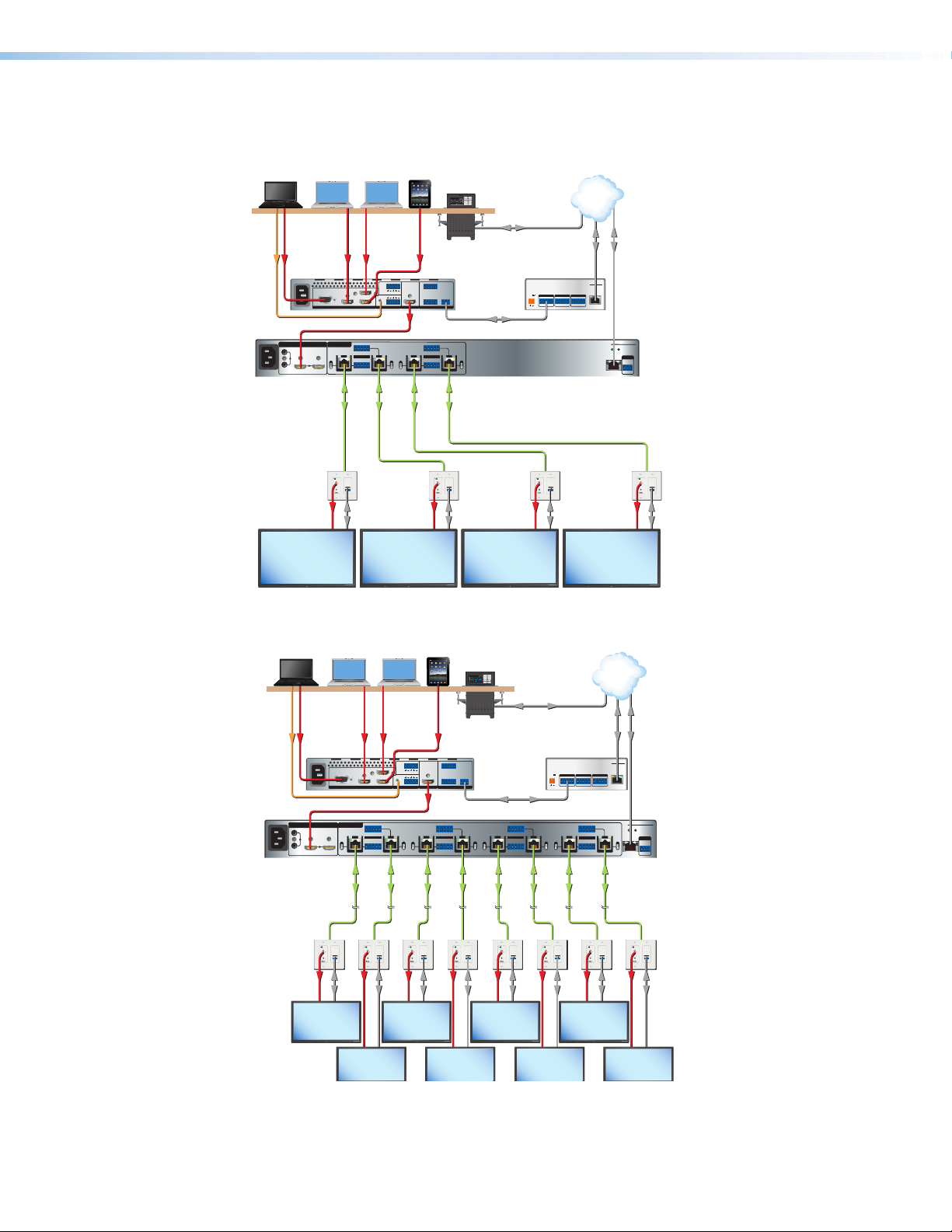
The diagrams below show typical applications for the DTP HD DA4/DA8 230/330.
Laptop Laptop Laptop
VGA
Audio HDMI HDMI HDMI
100-240V ~ --A MAX
50-60 Hz
INPUT
AUDIO
HDMI
100-240V ~ --A MAX
50/60 Hz
Extron
DTP HD DA4 4K 330
DTP Distribution Amplier
HDMI HDMI3
21CONFIGURABLE
HDMI4
INPUT REMOTE
RS-232 IR
OUTPUTS
1
Tx Rx Tx RxG
LINK
SIG
OVER TP
HDBT
RS-232 IR
OUT
Tx Rx Tx RxG
DTP
LOOP THRU
1 2
SIG
OUT
OUT
L R
IN
L
AUDIO OUTPUT
HDMI
2
LINK
HDBT
DTP
LAPTOP
DISPLAY ON
DVD
Combined
PC
DISPLAY OFF
DVD
MUTE
DOC CAM
VOLUME
VideoMore
AUXILIARY
VOLUME
Extron
TLP Pro 320C
3.5" Cable Cubby
TouchLink Pro
Touchpanel
TCP/ IP
Network
Tablet
iPad
Ethernet
Ethernet
Extron
IPL Pro S3
IP Link Pro Control
321 4 +V
Extron
TALLY OUT
HDMI
R
CONTACT IN
1 2 3 4 G
RS-232
TxRx G
IN160 4 HD
Four Input
Scaler
Processor
POWER
12V
COM 1 COM 2 COM 3
0.3A MAX
Tx Rx RTS CTS
G
Tx Rx RTS CTS
G
Tx Rx RTS CTS
Ethernet
IPL PRO S3
G
LAN / PoE
RS-232
RS-232 IR
3
4
Tx Rx Tx RxG
LINK
LINK
SIG
SIG
OVER TP
RS-232 IR
Tx Rx Tx RxG
HDBT
OUT
DTP
HDBT
OUT
DTP
DTP HD DA4 330
RESET
REMOTE
RS-232
LAN
Tx Rx
G
CATx Cable
up to 330' (100 m)
Extron
DTP HDMI
4K 330 D Rx
Receiver
MODEL 80
Display with Speakers
HDMI
FLAT PANEL
OUTPUTS
OVER DTP
RS-232 IR
AUDIO
TxRxGTx Rx
RS-232
MODEL 80
FLAT PANEL
CATx Cable
up to 330' (100 m)
OUTPUTS
OVER DTP
RS-232 IR
AUDIO
TxRxGTx Rx
RS-232HDMI RS-232HDMI RS-232
MODEL 80
FLAT PANEL
Extron
OUTPUTS
DTP HDMI
OVER DTP
RS-232 IR
AUDIO
TxRxGTx Rx
4K 330 D Rx
Receiver
MODEL 80
Display with Speakers
HDMI
FLAT PANEL
OUTPUTS
OVER DTP
RS-232 IR
AUDIO
TxRxGTx Rx
Figure 1. DTP HD DA4 4K 230/330 Application Diagram
RS-232
TxRx G
4
LINK SIG
OUT
LAPTOP
DISPLAY ON
DVD
Combined
PC
DISPLAY OFF
DVD
MUTE
DOC CAM
VOLUME
VideoMore
AUXILIARY
VOLUME
Extron
IN160 4 HD
Four Input
Scaler
5
HDBT
HDBT
OUT
DTP
DTP
Extron
TLP Pro 320C
3.5" Cable Cubby
TouchLink Pro
Touchpanel
Ethernet
Extron
IPL Pro S3
IP Link Pro Control
Processor
RS-232
RS-232 IR
6
Tx Rx Tx RxG
LINK SIG
LINK SIG
OVER TP
HDBT
RS-232 IR
OUT
Tx Rx Tx RxG
DTP
POWER
12V
0.3A MAX
HDBT
DTP
COM 1 COM 2 COM 3
G
Tx Rx RTS CTS
G
Tx Rx RTS CTS
RS-232 IR
7
Tx Rx Tx RxG
LINK SIG
OVER TP
RS-232 IR
OUT
Tx Rx Tx RxG
Ethernet
Tx Rx RTS CTS
TCP/ IP
Network
IPL PRO S3
G
LAN / PoE
8
LINK
HDBT
OUT
DTP
Ethernet
RS-232 Insertion
from Ethernet for
Display Control
DTP HD DA8 230
RESET
REMOTE
RS-232
LAN
Tx Rx
G
Laptop Lap top La ptop
Audio HDMI HDMI HDMI
VGA
100-240V ~ --A MAX
HDMI HDMI3
21CONFIGURABLE
INPUT REMOTE
50-60 Hz
Tab let
iPad
L R
L
R
AUDIO OUTPUT
321 4 +V
TALLY OUT
HDMI
CONTACT IN
1 2 3 4 G
OUT
IN
1 2
HDMI4
HDMI
INPUT
AUDIO
HDMI
100-240V ~ --A MAX
50/60 Hz
Extron
DTP HD DA8 4K 330
DTP Distribution Amplier
LOOP THRU
RS-232 IR
OUTPUTS
1
Tx Rx Tx RxG
SIG
LINK SIG
OVER TP
HDBT
RS-232 IR
OUT
OUT
Tx Rx Tx RxG
DTP
2
LINK SIG
HDBT
DTP
RS-232 IR
3
Tx Rx Tx RxG
LINK SIG
OVER TP
HDBT
RS-232 IR
OUT
Tx Rx Tx RxG
DTP
Extron
DTP HDMI
4K 330 D Rx
Receiver
Displays with
Speaker s
CATx Cable
up to 330' (100 m)
OUTPUTS
AUDIO
HDMI
MODEL 80
FLAT PANEL
OVER DTP
RS-232 IR
TxRxGTx Rx
RS-232
MODEL 80
OUTPUTS
OUTPUTS
OUTPUTS
OUTPUTS
OVER DTP
OVER DTP
RS-232 IR
AUDIO
AUDIO
TxRxGTx Rx
MODEL 80
FLAT PANEL
OVER DTP
RS-232 IR
RS-232 IR
AUDIO
TxRxGTx Rx
TxRxGTx Rx
MODEL 80
MODEL 80
OUTPUTS
OVER DTP
OVER DTP
RS-232 IR
AUDIO
FLAT PANEL
RS-232 IR
AUDIO
TxRxGTx Rx
TxRxGTx Rx
MODEL 80
MODEL 80
OUTPUTS
OVER DTP
RS-232 IR
AUDIO
TxRxGTx Rx
FLAT PANEL
CATx Cable
up to 330' (100 m)
OUTPUTS
AUDIO
MODEL 80
Extron
DTP HDMI
OVER DTP
RS-232 IR
TxRxGTx Rx
4K 330 D Rx
Receiver
RS-232HDMI
Figure 2. DTP HD DA8 4K 230/330 Application Diagram
Extron DTP HD DA4 4K 230/330 and DTP HD DA8 4K 230/330 • Introduction 3
Page 9

Installation and Operation
This section of the guide describes the following topics concerned with the installation,
setup, and operation of the DTP HD DA4 and DTP HD DA8 series of distribution amplifiers.
z Mounting the Units
z Front Panel Features
z Rear Panel Features
z Connecting the Input Source
z Twisted Pair Recommendations for DTP Communication
z Wiring for RS‑232 Control
Mounting the Units
ATTENTION:
• Installation and service must be performed by authorized personnel only.
• L’installation et l’entretien doivent être effectués par le personnel autorisé
uniquement.
The DTP HD DA4 and DTP HD DA8 series of distribution amplifiers can be placed on a
table, mounted in a rack, or mounted under a desk or table.
Tabletop Use
Affix the included rubber feet to the bottom of the unit and place it in any convenient
location.
Mounting Kits
Mount the unit using any optional compatible mounting kit listed on the Extron website
(www.extron.com), in accordance with the directions included with the kit. For rack
mounting, see UL Rack‑Mounting Guidelines on the next page.
Extron DTP HD DA4 4K 230/330 and DTP HD DA8 4K 230/330 • Installation and Operation 4
Page 10
UL Rack-Mounting Guidelines
The following Underwriters Laboratories (UL) requirements pertain to the installation of the
unit into a rack.
• Elevated operating ambient temperature — If installed in a closed or multi-unit rack
assembly, the operating ambient temperature of the rack environment may be greater
than room ambient. Therefore, consider installing the equipment in an environment
compatible with the maximum ambient temperature (TMA = +122 °F, +50 °C) specified
by Extron.
• Reduced air flow — Installation of the equipment in a rack should be such that the
amount of air flow required for safe operation of the equipment is not compromised.
• Mechanical loading — Mounting of the equipment in the rack should be such that a
hazardous condition is not achieved due to uneven mechanical loading.
• Circuit overloading — Consideration should be given to the connection of the
equipment to the supply circuit and the effect that overloading of the circuits might have
on overcurrent protection and supply wiring. Appropriate consideration of equipment
nameplate ratings should be used when addressing this concern.
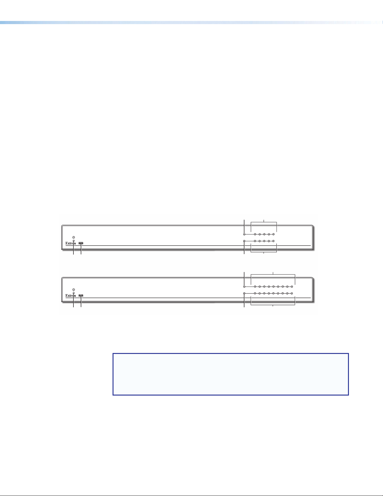
Front Panel Features
C
E
LOOP
THRU
LOOP
THRU
1
1
OUTPUTS
2
2
34
OUTPUTS
34
E
DTP HD DA4 Series
DTP DISTRIBUTION AMPLIFIER
5
6
7
8
DTP HD DA8 Series
DTP DISTRIBUTION AMPLIFIER
INPUT
SIGNAL
CONFIG
A B F
HDCP
D
C
INPUT
SIGNAL
CONFIG
A B F
Power status LED — Lights green when power is applied to the unit.
A
USB Config port — Used for firmware updates, SIS configuration, and software
B
HDCP
D
control. This port can be used as an alternative to the rear panel Remote RS-232 captive
screw connector.
NOTES:
• Neither port has precedence and commands from either port are handled in
the order they are received.
• Extron recommends that the USB port is used for temporary connections.
If a permanent connection is required, the RS-232 port should be used.
Input Signal LED — Lights green when a signal is detected on the HDMI input.
C
Input HDCP LED — Lights green when HDCP presence is detected on the HDMI
D
input.
Output Signal LEDs — Light green when a signal is detected on the HDMI outputs.
E
Output HDCP LEDs — Light green when HDCP presence is detected on the HDMI
F
outputs.
Extron DTP HD DA4 4K 230/330 and DTP HD DA8 4K 230/330 • Installation and Operation 5
Page 11

Rear Panel Features
B
B D E F G H J K
A C I
100-240V 1.0A
50/60Hz
A C I
100-240V 1.0A
50/60Hz
AUDIO
INPUT
HDMI
LOOP THRU
HDBT
DTP
OUTPUTS
1
SIG LINK
OUT
RS-232 IR
Tx Rx Tx RxG
OVER TP
RS-232 IR
Tx Rx Tx RxG
2
SIG LINK
OUT
RS-232 IR
3
Tx Rx Tx RxG
SIG LINK
HDBT
HDBT
DTP
DTP
RS-232 IR
Tx Rx Tx RxG
OUT
OVER TP
4
SIG LINK
OUT
HDBT
HDBT
DTP
DTP
B D E F G H J K
AUDIO
INPUT
HDMI
LOOP THRU
HDBT
DTP
OUTPUTS
1
SIG LINK
OUT
RS-232 IR
Tx Rx Tx RxG
OVER TP
RS-232 IR
Tx Rx Tx RxG
2
SIG LINK
OUT
RS-232 IR
3
Tx Rx Tx RxG
SIG LINK
HDBT
HDBT
DTP
DTP
RS-232 IR
Tx Rx Tx RxG
OUT
OVER TP
4
SIG LINK
OUT
HDBT
HDBT
HDBT
DTP
DTP
DTP
5
SIG LINK
OUT
RS-232 IR
Tx Rx Tx RxG
OVER TP
RS-232 IR
Tx Rx Tx RxG
SIG LINK
OUT
6
HDBT
HDBT
DTP
DTP
7
SIG LINK
OUT
RS-232 IR
Tx Rx Tx RxG
OVER TP
RS-232 IR
Tx Rx Tx RxG
8
SIG LINK
OUT
HDBT
DTP
DTP HD DA4 330
RESET
REMOTE
RS-232
LAN
Tx Rx
DTP HD DA8 330
RESET
REMOTE
RS-232
LAN
Tx Rx
G
G
Power input
A
Analog audio input
B
Analog audio Loop Thru
C
HDMI input
D
HDMI Loop Thru
E
DTP/HDBaseT configuration switches
F
Power input — Connect the provided IEC connector to a 100-240 VAC (50 or 60 Hz)
A
DTP/HDBaseT outputs
G
Over TP RS‑232/IR connectors
H
Reset button and LED
I
LAN connector
J
Remote RS‑232 connector
K
power source.
Analog audio input — Connect an unbalanced stereo audio source to these 3.5 mm
B
mini stereo jacks.
NOTE: The units do NOT embed analog audio onto the HDMI signal. This analog
audio signal is transmitted simultaneously with audio embedded within the HDMI
C
signal.
Analog audio Loop‑Thru — Connect an audio system to this 3.5 mm mini stereo jack
for local loop-through monitoring of the source audio.
HDMI input — Connect a source device to this female HDMI type A connector (see
D
Connecting the Input Source on page 8 for more information).
HDMI Loop Thru — Connect a display to this female HDMI type A connector for local
E
loop-through monitoring of the source signal (see Connecting the Input Source on
page 8 for more information).
DTP/HDBaseT configuration switch — Set this 2-position, recessed switch
F
to configure the output between HDBaseT and DTP modes. When configured for
HDBaseT, use an HDBaseT-compatible receiver. When configured for DTP, use a
DTP-compatible receiver.
Extron DTP HD DA4 4K 230/330 and DTP HD DA8 4K 230/330 • Installation and Operation 6
Page 12

DTP/HDBaseT outputs — Use STP cables to connect these 4 (DA4 models) or 8
RS‑232 IR
RS-232 Device
Pins:
T568B T568AT568BTIA/EIA-T568B
Tx Rx G Tx Rx
IR
Tx Rx G Tx Rx
RS-232
G
(DA8 models) outputs (see illustration on page 6) to the inputs of a compatible receiver
(see Twisted Pair Recommendations for DTP Communication on page 9 for more
information).
ATTENTION:
• Do not connect these outputs to a telecommunications or computer data
network.
• Ne connectez pas ces appareils à des données informatiques ou à un réseau
de télécommunications.
RS‑232 Over TP port — To pass bidirectional serial control between
H
DTP-compatible or HDBaseT-compatible devices, connect a control device
to the 5-pole captive screw connector. This port includes only the 3 poles
labeled “RS-232” (see image below for wiring instructions).
IR Over TP port — To transmit and receive IR signals, connect a control
device to the 5-pole captive screw connector. This port includes only the
2 poles labeled “IR” and shares the ground pole with the RS-232 port
(see image below for wiring instructions).
IR Device
TxRx
Tx/Rx
Pins
RxTx
Gnd
RS-232
IR
Rx GTx
RxTx
Gnd
NOTE: RS-232 and IR data can be transmitted simultaneously.
Reset button and LED — To reset the unit to factory default settings, press and hold
I
this reset button for approximately 9 seconds. The reset LED will flash green 3 times,
once every 3 seconds. After the third flash, release the button and quickly press it once
more to complete the reset. The LED will flash green 3 times indicating that the default
settings have been restored.
LAN (Ethernet) connector — Use an RJ-45 cable to connect this jack to a LAN
J
(Ethernet) for control of the device.
• Use a straight-through cable for connection to a switch, hub, or router.
• Use a crossover cable or a straight-through cable for connection directly to a PC.
Wire the connector as shown in the image below.
12345678
Crossover Cable
(for direct connection to a PC)
End 1 End 2
Pin Wire Color Pin Wire Color
1 white-orange 1 white-green
2 orange 2 green
3 white-green 3 white-orange
4 blue 4 blue
5 white-blue 5 white-blue
6 green 6 orange
7 white-brown 7 white-brown
8 brown 8 brown
RJ-45
Connector
Insert Twisted
Pair Wires
Straight-through Cable
(for connection to a switch, hub, or router)
End 1 End 2
Pin Wire Color Pin Wire Color
1 white-orange 1 white-orange
2 orange 2 orange
3 white-green 3 white-green
4 blue 4 blue
5 white-blue 5 white-blue
6 green 6 green
7 white-brown 7 white-brown
8 brown 8 brown
Remote RS‑232 connector — To control the unit, connect an RS-232 device to this
K
3-pole, 3.5 mm captive screw connector and configure it as follows: 9600 baud rate,
8 data bits,1 stop bit, no parity (see Wiring for RS‑232 Control on page 10 for more
information).
Extron DTP HD DA4 4K 230/330 and DTP HD DA8 4K 230/330 • Installation and Operation 7
Page 13

Connecting the Input Source
Use an HDMI cable to connect the input source to the female HDMI socket on the rear panel
(see D on page 6).
Follow these instructions to secure the input and output HDMI connectors to the unit with the
LockIt HDMI lacing bracket provided:
1. Plug the HDMI cable into the rear panel connection.
2. Loosen the HDMI connection mounting screw from the panel enough to allow the LockIt
lacing bracket to be placed over it. The screw does not have to be removed.
3. Place the LockIt lacing bracket on the screw and against the HDMI connector, then tighten
the screw to secure the bracket.
ATTENTION:
• Do not overtighten the HDMI connection mounting screw. The shield it fastens to is
very thin and can easily be stripped.
• Ne serrez pas trop la vis de montage de la connexion HDMI. Le blindage
auquel elle est attachée est très fin et peut facilement être dénudé.
4. Loosely place the included tie wrap around the HDMI connector and the LockIt lacing
bracket as shown.
5. While holding the connector securely against the lacing bracket, tighten the tie wrap, then
remove any excess length.
Extron DTP HD DA4 4K 230/330 and DTP HD DA8 4K 230/330 • Installation and Operation 8
Page 14

Twisted Pair Recommendations for DTP Communication
TP Wires
Pins:
Use the following pin configurations for shielded twisted pair cables.
12345678
Figure 3. Twisted Pair Cable Configuration
Supported Cables
The distribution amplifiers are compatible with shielded twisted pair cable (F/UTP, SF/UTP,
and S/FTP).
ATTENTION:
• Do not use Extron UTP23SF-4 Enhanced Skew-Free AV UTP cable or STP201
cable to link the device with DTP transmitters or receivers.
• N’utilisez pas le câble AV Skew-FreeUTP version améliorée UTP23SF d’Extron
ou le câble STP201 pour relier le appareil avec les émetteurs ou les récepteurs
DTP.
TIA/EIA T
Pin
Wire color
White-orange
1
Orange
2
3
White-green
4
Blue
5
White-blue
Green
6
7
White-brown
8
Brown
568 B
Cable Recommendations
Extron recommends using the following practices to achieve full transmission distances and
reduce transmission errors.
• Use the following Extron XTP DTP 24 SF/UTP cables and connectors for the best
performance:
• XTP DTP 24/1000 Non-Plenum 1000’ (305 m) spool 22-236-03
• XTP DTP 24P/1000 Plenum 1000’ (305 m) spool 22-235-03
• XTP DTP 24 Plug Package of 10 101-005-02
• If not using XTP DTP 24 cable, at a minimum, Extron recommends 24 AWG, solid
conductor, STP cable with a minimum bandwidth of 400 MHz.
• Terminate cables with shielded connectors to the TIA/EIA-T568B standard.
• Limit the use of more than two pass-through points, which may include patch points,
punch down connectors, couplers, and power injectors. If these pass-through points
are required, use shielded couplers and punch down connectors.
NOTE: When using shielded twisted pair cable in bundles or conduits, consider the
following:
• Do not exceed 40% fill capacity in conduits.
• Do not comb the cable for the first 20 meters, where cables are straightened,
aligned, and secured in tight bundles.
• Loosely place cables and limit the use of tie wraps or hook-and-loop fasteners.
• Separate twisted pair cables from AC power cables.
Extron DTP HD DA4 4K 230/330 and DTP HD DA8 4K 230/330 • Installation and Operation 9
Page 15

Wiring for RS-232 Control
REMOTE
DB9 Pin Locations
DTP HD DA4/DA8 230/330
RS-232 communication between the distribution amplifier and a host PC can be used to update
firmware or configure the unit using SIS commands (see Command and Response Table for
SIS Commands on page 16).
The computer connects to either the rear panel 3-pole RS-232 port (K on page 7) or the front
panel USB port (B on page 5) of the distribution amplifier.
NOTES:
• Neither port has precedence and commands from either port are handled in the
order they are received.
• Extron recommends that the USB port is used for temporary connections. If a
permanent connection is required, the RS-232 port should be used.
1. Connect an RS-232 cable to the computer, using a female 9-pin D connector (see figure 4):
z Data received by the computer = pin 2
z Data transmitted by the computer = pin 3
z Ground = pin 5
2. Wire the opposite end of the cable to the provided 3-pole captive screw plug (see figure4):
z Data transmitted by the DA plugs into the Tx (transmit) port
z Data received by the DA plugs into the Rx (receive) port
z Ground plugs into the G (ground) port
NOTES:
• The wiring in the RS-232 cables crosses over so that the Tx on the distribution
amplifier connects to the Rx of the control device and vice versa. Ground always
connects to ground.
• If the cable has a drain wire, tie the drain wire to the ground at both ends.
51
96
Female
Computer
Pin 2 = Rx
Pin 3 = Tx
Pin 5 = G
TransmitReceive
ReceiveTransmit
GroundGround
RS-232
Tx Rx G
Figure 4. Wiring the DTP HD DA4 and DA8 Series for RS‑232 Control
Extron DTP HD DA4 4K 230/330 and DTP HD DA8 4K 230/330 • Installation and Operation 10
Page 16

SIS Commands
This section provides information about the SIS commands that are used to configure the
DTP HDDA4 and DTP HD DA8 series. The following topics are discussed:
z Introduction to SIS
z Symbols Used in this Guide
z DTP HD DA4/DA8 EDID Memory Locations
z Command and Response Table for SIS Commands
Introduction to SIS
The distribution amplifiers can be set up and controlled remotely via Extron SIS commands that
are issued from a host computer running the Extron DataViewer utility or other control system.
The host device can be connected to the RJ-45 LAN connector on the rear panel, the 3-pole
captive screw connector on the rear panel, or to the mini USB config port on the front panel.
The serial protocol is 9600 baud, 8 data bit, 1 stop bit, and no parity.
NOTE: The wiring in the RS-232 cables crosses over so that the distribution amplifier
transmit (Tx) wire connects with the control device receive (Rx) and vice versa.
Host-to-Distribution Amplifier Communications
SIS commands consist of strings (one or more characters per command field). No special
characters are required to begin or end a command sequence. Unless otherwise stated, upper
and lower case characters can be used interchangeably. Most responses from the distribution
amplifier ends with a carriage return and a line feed (CR/LF = ]), which signals the end of the
response character string. When the switcher determines that a command is valid, it executes
the command and sends a response to the host device.
Distribution Amplifier-initiated Messages
When a local event such as a change in signal status takes place, the distribution amplifier
responds by sending a message to the host, indicating the status change. No response is
required from the host.
Copyright Information
The copyright message is displayed upon connecting to a DA via TCP/IP or Telnet or after a
power cycle via RS-232.
] © Copyright 20yy, Extron Electronics, DTP HD DA4/DA8 4K 230/330,
Vx.xx, 60-xxxx-01]
Mon, 2 Feb 2015 11:27:33 ]
20yy is the year the currently installed firmware was released, Vx.xx is the firmware version
number, and 60-xxxx-01 is the catalog part number.
This is followed by a Password prompt if a password has been set.
Extron DTP HD DA4 4K 230/330 and DTP HD DA8 4K 230/330 • SIS Commands 11
Page 17

Symbols Used in this Guide
ASCII to HEX Conversion Ta ble
Space
When programming in the field, certain characters are most conveniently represented by their
hexadecimal rather than their ASCII values. The table below shows the hexadecimal equivalent of
each ASCII character:
Table 1. ASCII to HEX Conversion Table
Symbol Definitions
]
| or }
E
or W
X!
X@
X#
X$
X%
X^
X&
X*
X1)
= Space
•
= Carriage return with line feed
= Carriage return with no line feed
= Escape
= Output selection
= Output status
= Video color bit depth
= EDID memory location
= EDID data as 256 bytes of hex
data (text representation)
= Native resolution and refresh
rate (translated from hex)
= Controller firmware version to
the second decimal place
= Unit name: Up to 24
alphanumeric characters
(including the hyphen [-])
= RS-232 mode
.
1 - 4 (DTP HD DA4 models)
1 - 8 (DTP HD DA8 models)
0 = disabled/off/undetected
1 = enabled/on/detected
0 = auto (based on EDID of sink)
1 = force 8-bit
See the DTP HD DA4/DA8 EDID Memory
Locations table on page 15.
Example: 1600x1200 @60Hz
No spaces allowed
No distinction between upper and lower case letters
First character must be a letter
Last character cannot be a hyphen (-)
Default is model name followed by last 3 digits of
MAC address
0 = RS-232 pass through
1 = Embedded RS-232
Extron DTP HD DA4 4K 230/330 and DTP HD DA8 4K 230/330 • SIS Commands 12
Page 18

= TMDS output format
X1!
= HDCP output mode
X1@
= DTP/HDBaseT switch position
X1#
= Verbose mode
X1$
= Set date/time MM/DD/YY-HH:MM:SS
X1%
= IP address
X1^
0 = Auto (default), pass through if HDMI sink, force
DVI format if DVI sink
1 = DVI RGB 444
2 = HDMI RGB “Full”
3 = HDMI RGB “Limited”
4 = HDMI YUV 444 “Limited”
5 = HDMI YUV 444 “Full”
6 = HDMI YUV 422 “Limited”
7 = HDMI YUV 422 “Full”
0 = Encrypt as required by input
(Continuous trials for HDMI sinks, attempt for 10
seconds on DVI sinks,then fail)
1 = Always encrypt
(Continuous trials for HDMI sinks, attempt for 10
seconds on DVI sinks,then fail)
2 = Encrypt as required by input
(Continuous trials for HDMI sinks and DVI sinks)
3 = Always encrypt
(Continuous trials for HDMI sinks and DVI sinks)
0 = DTP mode
1 = HDBaseT mode
0 = Clear/none (default for telnet)
1 = Verbose mode (default for RS-232 and USB)
2 = Tagged responses for queries
3 = Verbose mode and tagged responses for queries
Example: Fri, 21 Jun 2002 10:54:00
xxx.xxx.xxx.xxx
(192.168.254.254 = default)
= MAC address
X1&
= Subnet mask
X1*
= Password 12 digits and alphanumeric characters for user or
X1(
00-05-A6-xx-xx-xx
xxx.xxx.xxx.xxx (255.255.0.0 = default)
admin passwords.
NOTE: / \ | * and space are invalid characters.
= Port number
X5&
= Baud rate Default = 9600
X5*
= Parity Odd, Even, None (default), Mark, Space (only the first
X5(
= Data bits
X6)
= Stop bits
X6!
= Port timeout intervals
X6$
= Start point for UART ports
X6%
= Video mute
X6^
Extron DTP HD DA4 4K 230/330 and DTP HD DA8 4K 230/330 • SIS Commands 13
01 = Remote RS-232/RS-422 port
02 = unused
03-10 = UARTs 1 through 8
Port 1 is fixed at 9600
letter is required)
7-8
(8 = default)
1, 2
(1 = default)
1-65000
(1 = 10 seconds; default = 30 - 300 seconds = 5
minutes, in 10-second increments)
1999 = default
0 = Video mute disabled
1 = Video mute
2 = Video and sync mute
Page 19

Error Messages
E01 — Invalid output channel number (too large)
E10 — Invalid command
E13 — Invalid value (too large)
EDID
User assigned mode
In user assigned mode, the user can select from 55 factory loaded EDID files, each categorized
by rate type (PC or HDTV), video format (DVI or HDMI), audio type (2-Ch or Multi-Ch), and native
resolution. The unit retains this setting after a power cycle.
Additionally, two user-loaded slots are available to save the EDID of any connected display.
EDIDs saved to these slots are retained after a power cycle. Upon a factory reset, these EDIDs
revert to the factory default (720p @ 60 Hz, 2-Ch audio).
A table showing the factory loaded EDID options is shown on the following page. The EDID
memory location is labelled X$ for consistency with the value in the SIS commands.
Extron DTP HD DA4 4K 230/330 and DTP HD DA8 4K 230/330 • SIS Commands 14
Page 20

File Name
device(s).
Manually populated by user
Type
Audio
Video
Format
Rate
Type
Rate
Refresh
Automatically populated with EDID from connected sink
Native
Resolution
X$
File Name
Type
Audio
Video
Format
Rate
Type
Rate
Refresh
Native
Resolution
2 1024x768 60 Hz PC DVI n/a EXN_DVI2_1024x768_60.bin 37 576p 50 Hz HDTV HDMI 2-ch EXN_HDMI21_576p50_2Ch Audio.bin
3 1280x720 60 Hz PC DVI n/a EXN_DVI3_1280x720_60.bin 38 720p 50 Hz HDTV HDMI 2-ch EXN_HDMI22_720p50_2Ch Audio.bin
4 1280x768 60 Hz PC DVI n/a EXN_DVI4_1280x768_60.bin 39* 720p 60 Hz HDTV HDMI 2-ch EXN_HDMI23_720p60_2Ch Audio.bin
5 1280x800 60 Hz PC DVI n/a EXN_DVI5_1280x800_60.bin 40 1080i 50 Hz HDTV HDMI 2-ch EXN_HDMI24_1080i50_2Ch Audio.bin
6 1280x1024 60 Hz PC DVI n/a EXN_DVI6_1280x1024_60.bin 41 1080i 60 Hz HDTV HDMI 2-ch EXN_HDMI25_1080i60_2Ch Audio.bin
7 1360x768 60 Hz PC DVI n/a EXN_DVI7_1360x768_60.bin 42 1080p 50/25 Hz HDTV HDMI 2-ch EXN_HDMI26_1080p50_25_2Ch Audio.bin
8 1366x768 60 Hz PC DVI n/a EXN_DVI8_1366x768_60.bin 43 1080p 50 Hz HDTV HDMI 2-ch EXN_HDMI27_1080p50_2Ch Audio.bin
1 800x600 60 Hz PC DVI n/a EXN_DVI1_800x600_60.bin 36 480p 60 Hz HDTV HDMI 2-ch EXN_HDMI20_480p60_2Ch Audio.bin
X$
DTP HD DA4/DA8 EDID Memory Locations
9 1400x1050 60 Hz PC DVI n/a EXN_DVI9_1400x1050_60.bin 44 1080p 60/24 Hz HDTV HDMI 2-ch EXN_HDMI28_1080p60_24_2Ch Audio.bin
10 1440x900 60 Hz PC DVI n/a EXN_DVI10_1440x900_60.bin 45 1080p 60 Hz HDTV HDMI 2-ch EXN_HDMI29_1080p60_2Ch Audio.bin
11 1600x900 60 Hz PC DVI n/a EXN_DVI11_1600x900_60.bin 46 4k / UHD 30 Hz HDTV HDMI 2-ch EXN_HDMI30_4KUHD_60_2Ch Audio.bin
12 1600x1200 60 Hz PC DVI n/a EXN_DVI12_1600x1200_60.bin 47 720p 50 Hz HDTV HDMI multi-ch EXN_HDMI31_720p50_MultiCh Audio.bin
13 1680x1050 60 Hz PC DVI n/a EXN_DVI13_1680x1050_60.bin 48 720p 60 Hz HDTV HDMI multi-ch EXN_HDMI32_720p60_MultiCh Audio.bin
14 1920x1080 60 Hz PC DVI n/a EXN_DVI14_1920x1080_60.bin 49 1080i 50 Hz HDTV HDMI multi-ch EXN_HDMI33_1080i50_MultiCh Audio.bin
15 1920x1200 60 Hz PC DVI n/a EXN_DVI15_1920x1200_60.bin 50 1080i 60 Hz HDTV HDMI multi-ch EXN_HDMI34_1080i60_MultiCh Audio.bin
16 2048x1080 60 Hz PC DVI n/a EXN_DVI16_2048x1080_60.bin 51 1080p 50/25 Hz HDTV HDMI multi-ch EXN_HDMI35_1080p50_25_MultiCh Audio.bin
Extron DTP HD DA4 4K 230/330 and DTP HD DA8 4K 230/330 • SIS Commands 15
17 800x600 60 Hz PC HDMI 2-ch EXN_HDMI1_800x600_60_2Ch Audio.bin 52 1080p 50 Hz HDTV HDMI multi-ch EXN_HDMI36_1080p50_MultiCh Audio.bin
18 1024x768 60 Hz PC HDMI 2-ch EXN_HDMI2_1024x768_60_2Ch Audio.bin 53 1080p 60/24 Hz HDTV HDMI multi-ch EXN_HDMI37_1080p60_24_MultiCh Audio.bin
19 1280x768 60 Hz PC HDMI 2-ch EXN_HDMI3_1280x768_60_2Ch Audio.bin 54 1080p 60 Hz HDTV HDMI multi-ch EXN_HDMI38_1080p60_MultiCh Audio.bin
20 1280x800 60 Hz PC HDMI 2-ch EXN_HDMI4_1280x800_60_2Ch Audio.bin 55 4k / UHD 30 Hz HDTV HDMI multi-ch EXN_HDMI39_4KUHD_30_MultiCh Audio.bin
21 1280x1024 60 Hz PC HDMI 2-ch EXN_HDMI5_1280x1024_60_2Ch Audio.bin 56 Loop-Through
22 1360x768 60 Hz PC HDMI 2-ch EXN_HDMI6_1360x768_60_2Ch Audio.bin 57 Output 1
23 1366x768 60 Hz PC HDMI 2-ch EXN_HDMI7_1366x768_60_2Ch Audio.bin 58 Output 2
24 1400x1050 60 Hz PC HDMI 2-ch EXN_HDMI8_1400x1050_60_2Ch Audio.bin 59 Output 3
25 1440x900 60 Hz PC HDMI 2-ch EXN_HDMI9_1440x900_60_2Ch Audio.bin 60 Output 4
26 1600x900 60 Hz PC HDMI 2-ch EXN_HDMI10_1600x900_60_2Ch Audio.bin 61 Output 5
27 1600x1200 60 Hz PC HDMI 2-ch EXN_HDMI11_1600x1200_60_2Ch Audio.bin 62 Output 6
28 1680x1050 60 Hz PC HDMI 2-ch EXN_HDMI12_1680x1050_60_2Ch Audio.bin 63 Output 7
29 1920x1200 60 Hz PC HDMI 2-ch EXN_HDMI13_1920x1200_60_2Ch Audio.bin 64 Output 8
30 1920x2160 60 Hz PC HDMI 2-ch EXN_HDMI14_1920x2160_60_2Ch Audio.bin 65 User loaded slot 1
31 2048x1080 60 Hz PC HDMI 2-ch EXN_HDMI15_2048x1080_60_2Ch Audio.bin 66 User loaded slot 2
32 2048x2160 60 Hz PC HDMI 2-ch EXN_HDMI16_2048x2160_60_2Ch Audio.bin *Default
33 2560x1080 60 Hz PC HDMI 2-ch EXN_HDMI17_2560x1080_60_2Ch Audio.bin
34 2560x1440 60 Hz PC HDMI 2-ch EXN_HDMI18_2560x1440_60_2Ch Audio.bin
35 2560x1600 60 Hz PC HDMI 2-ch EXN_HDMI19_2560x1600_60_2Ch Audio.bin
Page 21

Command and Response Table for SIS Commands
Command ASCII Command
(host to unit)
Video Mute
Video mute single output
Video mute all outputs
Query video mute status
Analog Audio Mute
Audio mute single output
Audio mute all outputs
Query audio mute status
HDMI (embedded) Audio Mute
Audio mute single output
Audio mute all outputs
Query audio mute status
TMDS Output Format
Set format for single output
Set format for all outputs
Query format settings
Video Color Bit Depth
Set video bit depth for a
single output
Set video bit depth for all
outputs
Query video bit depth for all
outputs
X!*X6^B/b VmtX!*X6^] Video mute output X! only
X6^B/b VmtX6^]
B/b
X!*X@Z/z AmtX!*X@] Audio mute output X! only
X@Z/z AmtX@]
Z/z
EX!*X@AFMT} AfmtX!*X@] Audio mute output X! only
EX@AFMT} AfmtX@]
EAFMT} AfmtX@•X@•...X@]
EX!*X1!VTPO} VtpoX!*X1!] X1! = 0-7
EX1!VTPO} VtpoX1!]
EVTPO} VtpoX@•X@•...X@]
EVX!*X#BITD} BitdVX!*X#] X# = 0 (auto, based on sink EDID)
EVX#BITD} BitdVX#] X# = 0 (auto, based on sink EDID)
EVBITD} BitdVX#•X#•...X#]
Response
(unit to host)
VmtX6^•X6^•...X6^]
AmtX@•X@•...X@]
Additional Description
1, 2, 3, or 4 (DA4)
1, 2, 3, 4, 5, 6, 7, or 8 (DA8)
X6^ = 0 (video mute disabled)
or 1 (video mute TMDS)
or 2 (video and sync mute)
Video mute status of outputs 1 to 4
(DA4) or 1 to 8 (DA8).
X@ = 0 (audio mute disabled)
or 1 (audio mute)
Audio mute status of outputs 1 to 4
(DA4) or 1 to 8 (DA8).
X@ = 0 (audio mute disabled)
or 1 (audio mute)
Audio mute status of outputs 1 to 4
(DA4) or 1 to 8 (DA8).
(0 = default)
TMDS settings of outputs 1 to 4
(DA4) or 1 to 8 (DA8).
1 (force 8-bit)
1 (force 8-bit)
Video bit depth of outputs 1 to 4
(DA4) or 1 to 8 (DA8).
Extron DTP HD DA4 4K 230/330 and DTP HD DA8 4K 230/330 • SIS Commands 16
Page 22

Command ASCII Command
(host to unit)
HDCP Output Mode
Set HDCP output mode for
a single output
Set HDCP output mode for
all outputs
Query HDCP output mode
for all outputs
Signal Status (unsolicited)
Request all signal status
Request all HDCP status
HDCP Authorized Device
HDCP authorization enable/
disable
Query HDCP authorization
status
EDID Minder
Assign EDID to input
View EDID assignment
Save EDID of output to user
location
View/Read EDID in Hex
View EDID native resolution
Import EDID to user slot
Upload EDID file to unit
Export EDID to file
Send file from unit to PC
ESX!*X1@HDCP} HdcpSX!*X1@] X1@ = 0 - 3 (0 is default)
ESX1@HDCP} HdcpSX1@] X1@ = 0 - 3 (0 is default)
ESHDCP} HdcpSX1@•X1@•...
ELS} SigX@*X@•X@•...X@]
EHDCP} HdcpX@*X@•X@•...X@]
EEX@HDCP} HdcpEX@] X@ = 0 (disabled)
EEHDCP} X@] X@ = 0 (disabled)
EAX$EDID} EdidAX$] X$ = EDID memory location (1 - 66)
EAEDID} X$]
ESX!*X$EDID} EdidSX!*X$]
EREDID} X%]
ENEDID} X^]
EIX$filenameEDID} EdidIX$]
E+UFsize,filename} Upl]
EEX$filenameEDID} EdidEX$]
EfilenameSF}
Response
(unit to host)
X1@]
File data (128 or 256
bytes)
Additional Description
Video bit depth of outputs 1 to 4
(DA4) or 1 to 8 (DA8).
Input * Outputs local-max
Input * Outputs local-max
1 (enabled, default)
1 (enabled, default)
see the DTP HD DA4/DA8 EDID
Memory Locations table on page
15 (default is 720p @ 60 Hz, 2-ch
audio)
Store the EDID of output X! into
EDID memory location X$ (65 or
66)
Read out EDID in Hex from currently
selected EDID
Resolution and refresh rate of
currently selected EDID
Example: 1600x1200@60Hz
Import EDID from filename into
specified user slot
X$ = 65 or 66
Export EDID from specified EDID
table slot to filename
X$ = 1 - 66
Send filename from unit to
connected PC
NOTE: filename can optionally carry a full path name. The EDID file format will be “.bin” carrying 128 or 256
bytes of binary data.
Extron DTP HD DA4 4K 230/330 and DTP HD DA8 4K 230/330 • SIS Commands 17
Page 23

Command ASCII Command
(host to unit)
IP Configuration/Setup
Set date/time
View date/time
Set DHCP mode
View DHCP mode
Set IP address
View IP address
View MAC address
Set subnet mask
View subnet mask
Set gateway IP address
View gateway IP address
Set DNS server IP address
View DNS server IP address
Get number of connections
Set admin password
Clear admin password
View admin password
Set user password
Clear user password
View user password
RS‑232 Insertion Port Setup
Enable output RS-232 port
Enable output UART port
Set all ports
View Insertion Port Setup
View output insert setting
View all output insert port
setting
EX1%CT} IptX1%]
ECT} X1%]
EX@DH} IdhX@]
EDH} X@]
EX1^CI} IpiX1^]
ECI} X1^]
ECH} X1&]
EX1*CS} IpsX1*]
ECS} X1*]
EX1^CG} IpgX1^]
ECG} X1^]
EX1^DI} IpdX1^]
EDI} X1^]
ECC}
EX1(CA} Ipa•X1(]
E•CA} Ipa•X1%]
ECA} X1(]
EX1(CU} Ipu•X1(]
E•CU} Ipu•]
ECU} X1(]
EOX!*0LRPT} LrptOX!*0]
EOX!*1LRPT} LrptOX!*1]
EOX1)*LRPT} LrptOX1)]
EOX!LRPT} X1)]
EOLRPT} X1)1X1)2X1)
Response
(unit to host)
{Number of connections}
X1%]
3
n
...X1)
] Verbose: LrptO00*X1)1X1)2X1)
Additional Description
Default = 192.168.254.254
Default = 255.255.0.0
Default = 0.0.0.0
Default = 0.0.0.0
Set RS-232 to pass through (default)
Set RS-232 to Ethernet insertion
Set all ports to pass through or
Ethernet insertion
View port setting
3
X1)n]
...
Extron DTP HD DA4 4K 230/330 and DTP HD DA8 4K 230/330 • SIS Commands 18
Page 24

Command ASCII Command
(host to unit)
Serial Port Configuration
Set serial port parameters
EX5&*X5*,X5(,X6),
X6!CP}
Query serial port
parameters
Configure current port
timeout
View current port timeout
Configure global port
timeout
View global port timeout
Set UART start point
Query UART start point
Unit Name
Set unit name
Set unit name to factory
default
View unit name
Other
Set verbose mode
Query verbose mode
Query DTP mode
Request part number
Query firmware version
Query firmware version with
build
Reset settings (retain IP
settings)
Reset all settings (including
IP settings)
EX5&CP} X5*,X5(,X6),X6!]
E0*X6$TC} Pti0*X6$]
E0TC} X6$]
E1*X6$TC} Pti1*X6$]
E1TC} X6$]
EX6%*MD} PmdX6%]
EMD} X6%]
EX*CN} Ipn•X*] X* = Up to 24 alphanumeric
E•CN} Ipn•{Default}]
ECN} X*]
EX1$CV} VrbX1$]
ECV} X1$]
EOHDBT} HdbtOX1#•X1#•X1#......
N/n
Q/q
*Q/q
EZXXX} Zpx]
EZQQQ} Zpq]
Response
(unit to host)
CpnX5&•CcpX5*,X5(,
X6),X6!]
X1#]
60-1437-01]
60-1438-01]
60-1437-51]
60-1438-51]
X&]
x.xx.xxxx]
Additional Description
Read port parameters
Set timeout
View timeout
Default = 1999
Output 1 uses 2001
Output 8 uses 2008
Read start point for UART
characters, including "-"
Example:
DTP-HD-DA8-330-0B-4A-45
(Model name and last 3 pairs of MAC
address)
DTP HD DA4 230
DTP HD DA8 230
DTP HD DA4 330
DTP HD DA8 330
Firmware build with 2 decimals
Extron DTP HD DA4 4K 230/330 and DTP HD DA8 4K 230/330 • SIS Commands 19
Page 25

Reference Information
This section provides information about updating the firmware of the DTP HD DA models.
The following topics are discussed:
z Using the Internal Web Pages
z Updating the Device Firmware
Using the Internal Web Pages
The DTP HD DA4/DA8 4K 230/330 Internal Web Pages allow for monitoring and set up of
the device via an Ethernet connection.
Accessing the Internal Web Pages
To access the Internal Web Pages:
1. Using an RJ-45 cable, connect the device to a LAN via the rear panel LAN connector
(see J on page 7).
2. Enter the device IP address into a Web browser address bar.
Extron DTP HD DA4 4K 230/330 and DTP HD DA8 4K 230/330 • Internal Web Pages 20
Page 26

Setting Up the Device with the Internal Web Pages
Output status
This section displays the status of all connected outputs. This section is not configurable.
Input status
This section displays the status of the connected input. This section is not configurable.
Device info
This section displays device information including:
• Device Name — Displays the device name. Click the Edit button to configure the
name.
• Part Number — Displays the device part number (non-configurable)
• Model Name — Displays the device model number (non-configurable)
• Model Description — Displays a description of the connected model (non-
configurable)
• Firmware Version — Displays the current firmware version number. Click the
Update button to load new firmware to the device (see the following section for more
information)
• Firmware Build — Displays the current firmware build (non-configurable)
Date/Time settings
This section displays the date and time settings of the device. Click Sync to PC to
automatically sync the time to the connected PC. Click Set Manually to set a desired
time.
Configure this device
Click the link in this section to go to the Extron website where the Product Configuration
Software (PCS) can be downloaded.
Communication settings
This section displays the TCP/IP and RS-232 device communications settings.
TCP/IP
If necessary, click the Edit button to change the TCP/IP settings.
RS-232
This section is non-configurable.
Passwords
Click the Set button to set up a password for the device.
Extron DTP HD DA4 4K 230/330 and DTP HD DA8 4K 230/330 • Internal Web Pages 21
Page 27

Updating the Device Firmware
Update the device firmware via either the Internal Web Pages or the Extron Firmware Loader
software.
Downloading Firmware
To obtain the latest version of firmware for your distribution amplifier:
1. At www.extron.com, click the Download link at the top of the page (figure 6,
click the Firmware link (2) on the left sidebar menu.
1
1
3
3
1
), then
22
Figure 5. Firmware Link on the Download Tab
2. On the Download Center screen, click the letter D (
3. (Optional) click Release Notes next to the necessary firmware. These notes show the
issues that are addressed by the latest update. If these issues do not affect the current
device, updating the firmware may not be necessary.
4. Locate the necessary firmware in the list and click Download.
5. On the next screen that appears, enter the requested user information, then click the
Download button.
6. Follow the instructions on the rest of the download screens to save the executable firmware
file to the computer. Note the folder to which the file was saved.
7. In Windows Explorer or another file browser, locate the downloaded executable file and
double-click it to run it.
8. Follow the instructions on the Installation Wizard screens to install the new firmware
on the computer. A Release Notes file and a set of instructions for updating the firmware are
also loaded.
3
).
Downloading and Installing Firmware Loader
Extron recommends using the Firmware Loader software to update the firmware on Extron
products. If Firmware Loader is not already installed on the connected computer, download it as
follows:
1. Go to www.extron.com and click the Download tab.
2. On the Download Center screen, click the Software link on the left sidebar menu.
Extron DTP HD DA4 4K 230/330 and DTP HD DA8 4K 230/330 • Internal Web Pages 22
Page 28

3. On the next Download Center screen, locate Firmware Loader and click its Download
link.
Figure 6. Firmware Loader Download Link
4. On the next screen, enter the requested information, then click the
Download fw_loader_vnxnxn.exe button (where n is the Firmware Loader version
number).
5. Follow the instructions on the rest of the download screens to save the executable Firmware
Loader installer file to the computer. Note the folder to which the file was saved.
6. In Windows Explorer or another file browser, locate the downloaded executable installer file
and double-click it to open it.
7. Follow the instructions on the Installation Wizard screens to install Firmware Loader on the
computer. Unless you specify otherwise, the installer program places the Firmware Loader
file, FWLoader.exe, at c:\Program Files\Extron\FWLoader.
Loading Firmware to the DA with Firmware Loader
To load a new version of firmware to the distribution amplifier using Firmware Loader, follow these
instructions.
11
1. If not already installed, download and install the Firmware Loader executable
installer file to the computer (see Downloading and Installing Firmware Loader on the
previous page).
2. If necessary, download the latest version of firmware for the desired product (see
Downloading Firmware on the previous page).
3. Connect the distribution amplifier to the computer using the front panel USB connector
(B on page5), the rear panel LAN connector (J on page 7), or the rear panel RS-232
connector (K on page 7).
4. Open Firmware Loader. If there is no desktop icon, open the program from the Start menu
by selecting:
Start > All Programs > Extron Electronics > Firmware Loader > Firmware
Loader
The Firmware Loader dialog box opens with the Add Device... dialog box in front of
it.
Figure 7. Opening Firmware Loader
Extron DTP HD DA4 4K 230/330 and DTP HD DA8 4K 230/330 • Internal Web Pages 23
Page 29

5. Select the DTP HD DA product from the Device Name menu.
6. Select RS-232, USB, or TCP/IP from the Connection Method menu.
7. Depending on the connection method that selected, additional options appear. Make the
appropriate selections for the connection method.
• RS‑232: Select the appropriate options from the Com Port and Baud Rate menus.
• USB: Only the Extron USB Device_0 option is available on the AvailableDevices
menu. Make sure that it is selected.
• TCP/IP: Enter the IP address (default is 192.168.254.254), port number, and
password (if necessary).
8. Click Connect. If the connection is successful, DTP HD DA4 4K 230/330 or
DTP HD DA8 4K 230/330 is displayed in green in the Connected Device panel, followed
by a green check mark.
9. Click Browse to locate the Firmware file that was downloaded in step 2.
ATTENTION:
• Valid firmware files must have the file extension S19. A file with any other
extension is not a firmware upgrade for this device and could cause the device
to stop functioning.
• Les fichiers firmware valides doivent contenir l’extension fichier S19. Un fichier
avec n’importe quelle autre extension n’est pas une mise à jour de firmware
pour cet appareil et l’appareil pourrait arrêter de fonctionner.
NOTES:
• The original factory-installed firmware is permanently available on the DA units.
If the attempted firmware upload fails for any reason, the unit reverts to the
factory version.
• By default, when the firmware is downloaded from the Extron site, it is saved in
one of the following paths:
C:\Program Files\Extron\Firmware\folder_name (Windows XP) or
C:\Program Files (x86)\Extron\Firmware\folder_name
(Windows7) where folder_name may be named for the specific model
needed.
10. If multiple units are connected to the computer, it is possible to upload the same firmware to
all of them. Click Add Next.
The first device is added to the Devices section and the Add Device... dialog box
remains open. Add additional devices, by repeating this step.
When adding the last device, (or if only updating a single unit) click Add (do not press Add
Next). The device is added to the device list in the Firmware Loader window and the
Add Device... dialog box closes.
11. Highlight the distribution amplifier in the device list and click Begin. The following indicators
show the progress of the update:
• The Transfer Time section shows the amounts of remaining and elapsed time for
the update.
• The Total Progress section displays a progress bar with Uploading... above it.
• In the Devices section, the Progress column displays an incrementing percentage
and another progress bar. The Status column displays Uploading.
12. The upload is complete when the Remaining Time field shows 00.00.00, the Progress
column shows 100%, and Completed is displayed above the progress bar and in the
Status field. Close the Firmware Loader dialog box.
Extron DTP HD DA4 4K 230/330 and DTP HD DA8 4K 230/330 • Internal Web Pages 24
Page 30

Loading Firmware to the DA with Internal Web Pages
1. Using an internet browser, navigate to the device Internal Web Pages.
2. In the Device Info section, click the Update button.
3. Click the Browse button and locate and select the desired firmware file, then click
Open.
4. Click the Upload button.
Extron DTP HD DA4 4K 230/330 and DTP HD DA8 4K 230/330 • Internal Web Pages 25
Page 31

Extron Warranty
Extron Electronics warrants this product against defects in materials and workmanship for a period of three years
from the date of purchase. In the event of malfunction during the warranty period attributable directly to faulty
workmanship and/or materials, Extron Electronics will, at its option, repair or replace said products or components,
to whatever extent it shall deem necessary to restore said product to proper operating condition, provided that it is
returned within the warranty period, with proof of purchase and description of malfunction to:
USA, Canada, South America,
and Central America:
Extron Electronics
1230 South Lewis Street
Anaheim, CA 92805
Japan:
Extron Electronics, Japan
Kyodo Building, 16 Ichibancho
Chiyoda-ku, Tokyo 102-0082
Japan
U.S.A.
Europe and Africa:
Extron Europe
Hanzeboulevard 10
3825 PH Amersfoort
The Netherlands
China:
Extron China
686 Ronghua Road
Songjiang District
Shanghai 201611
China
Asia:
Extron Asia Pte Ltd
135 Joo Seng Road, #04-01
PM Industrial Bldg.
Singapore 368363
Middle East:
Extron Middle East
Dubai Airport Free Zone
F12, PO Box 293666
United Arab Emirates, Dubai
Singapore
This Limited Warranty does not apply if the fault has been caused by misuse, improper handling care, electrical
or mechanical abuse, abnormal operating conditions, or if modifications were made to the product that were not
authorized by Extron.
NOTE: If a product is defective, please call Extron and ask for an Application Engineer to receive an RA (Return
Authorization) number. This will begin the repair process.
USA: 714.491.1500 or 800.633.9876 Europe: 31.33.453.4040
Asia: 65.6383.4400 Japan: 81.3.3511.7655
Units must be returned insured, with shipping charges prepaid. If not insured, you assume the risk of loss or damage
during shipment. Returned units must include the serial number and a description of the problem, as well as the
name of the person to contact in case there are any questions.
Extron Electronics makes no further warranties either expressed or implied with respect to the product and its quality,
performance, merchantability, or fitness for any particular use. In no event will Extron Electronics be liable for direct,
indirect, or consequential damages resulting from any defect in this product even if Extron Electronics has been
advised of such damage.
Please note that laws vary from state to state and country to country, and that some provisions of this warranty may
not apply to you.
Extron Headquarters
+1.800.633.9876 (Inside USA/Canada Only)
Extron USA - West Extron USA - East
+1.714.491.1500 +1.919.850.1000
+1.714.491.1517 FAX +1.919.850.1001 FAX
Extron Europe
+800.3987.6673
(Inside Europe Only)
+31.33.453.4040
+31.33.453.4050 FAX
Extron Asia
+65.6383.4400
+65.6383.4664 FAX
© 2015 Extron Electronics All rights reserved. www.extron.com
Extron Japan
+81.3.3511.7655
+81.3.3511.7656 FAX
Extron China
+86.21.3760.1568
+86.21.3760.1566 FAX
Extron Middle East
+971.4.299.1800
+971.4.299.1880 FAX
Extron Korea
+82.2.3444.1571
+82.2.3444.1575 FAX
Extron India
1800.3070.3777
(Inside India Only)
+91.80.3055.3777
+91.80.3055.3737 FAX
 Loading...