

Page 1
TLP Pro 1220, 1520, and TLP Pro 1720TG • Setup Guide
Go to www.extron.com for the
complete user guide and installation
instructions before connecting the
product to the power source.
Overview
IMPORTANT:
The Extron TLP Pro 1220TG, TLP Pro 1520TG, and TLP Pro 1720TG are table-top touchpanels with high resolution capacitive touch
screens.
with a 1366x768 resolution. The TLP Pro 1720TG has a 17.3 inch screen with a 1920x1080 resolution. They are ideal for any
AV applications requiring large touchpanels with exible mounting options and fully customizable interfaces. This guide provides
instructions for experienced installers to mount and install these touchpanels. For more complete procedures, see the TLPPro 1220,
TLPPro 1520, and TLP Pro 1720 Series User Guide at www.extron.com.
The TLP Pro 1220TG has a 12.1 inch screen with a 1280x800 resolution. The TLP Pro 1520TG has a 15.6 inch screen
Setup Overview and Checklist
Get Ready
Download and install the latest version of the following software:
• GUI Designer — For designing layouts for Extron TouchLink® Pro touchpanels and third party touch interfaces.
• Global Configurator
• Toolbelt — For device discovery, device information, rmware updates, and conguration of network settings, system
utilities, and user management for TouchLink Pro devices.
• Global Scripter
NOTE: All four software programs are available from www.extron.com.
Obtain the following network information from your network administrator:
DHCP status (on or off). If DHCP is off, you also require:
®
Plus and Professional — For setting up and conguring the control processor and touchpanel.
®
— Provides an integrated development environment for Extron control systems programming.
IP address Subnet mask Gateway
Username — This can be either admin or user.
Passwords — The factory congured passwords for all accounts on this device have been set to the device serial number.
Passwords can be changed during conguration. Passwords are case sensitive
NOTE: If the device is reset to default settings, the passwords are reset to the default password, which is extron (for
either admin or user).
Make a note of the touchpanel MAC address.
Mount and Cable All Devices
ATTENTION:
• Do not power on the touchpanels or control processors until you have read the Attention in the Power Supply section of the
TLPPro 1220, TLPPro 1520, and TLP Pro 1720 Series User Guide or the IPL Pro User Guide.
• Ne branchez pas les écrans tactiles ou les contrôleurs avant d’avoir lu la mise en garde dans la section «sources
d’alimentation» du TLPPro 1220, TLPPro 1520, and TLP Pro 1720 Series User Guide ou du IPLProUserGuide.
Mount the units. There are several mounting options for TouchLink Pro touchpanels (see Mounting on the following page).
Connect cables to the touchpanels. To connect cables, remove the back and base covers (see figure 1 on the following page).
For more information about the cable connectors, see Rear Panel Features on page 4.
Connect the power cords and power on all devices.
Set up the Touchpanels for Network Communication
Connect the PC that you will use for setup, the control processor, and touchpanel to the same Ethernet subnetwork.
Use the Setup Menu (see page 5) or Toolbelt to set the DHCP status and, if necessary, the IP address, subnet mask, gateway,
and related settings for the touchpanel.
Configure the Touchpanels
Create a graphical user interface with GUI Designer (see GUI Designer Help File for step-by-step instructions).
Associate functions with the graphical user interface features by conguring (see the Global Configurator Help File) or
programming (see the Global Scripter Help File) the system. Global Scripter provides an Extron-exclusive Python library
(ControlScript
®
) and Global Scripter modules to get you started.
1
Page 2

TLP Pro 1220, 1520, and 1720TG • Setup Guide (cont’d)
2
Mounting
A range of optional mounting kits are available for all three models. The
kits must be purchased separately. Follow the installation instructions
provided with the kit.
Removing the back and base covers
Some of these procedures require the back and base covers to be
removed. You must remove the back cover before you can remove the
base cover.
1. Use the provided Extron removal tool. There is one notch on each
side of the back cover (gure 1,
release the catch.
2. Use the removal tool to remove the base cover. There are two
notches at the back of the base (2).
). Insert the tool into the notch to
1
Desktop Mounting
The TLP Pro 1220TG, TLP Pro 1520TG, and TLP Pro 1720TG
come assembled with stands that allow the units to be placed on
any suitable at surface (for example a desk, table, or lectern).
Fixed Mounting
Figure 2 shows the base of the TLPPro1220TG, with the cover
removed to indicate the position of the mounting holes. The bases
of the TLP Pro 1520 TG and TLP Pro 1720TG are similar and the
spacing of the mounting holes (gure 2,
1. Mark the location for two holes, 4.96inches (126 mm) apart.
This measurement is the same for all three models.
2. Drill two pilot holes into the desktop.
3. Remove the base cover (see Removing the Back and Base
Covers, above).
4. Insert two #10 at-head wood screws (not provided) through
the touchpanel and align them with the two pilot holes.
5. Secure the touchpanel to the tabletop.
6. Replace the base cover.
®
Kensington
For added security, attach a Kensington Security Lock
(not provided) to the metal-reinforced Kensington Security
Slot on the rear edge of the base (gure 3,
shows the rear edge of the TLP Pro 1520TG base, but the
bases of the TLP Pro 1220TG and TLP Pro 1720TG are
very similar. Follow the instructions that are provided by the
manufacturer to install the lock.
Security Lock
) is identical.
1
). The gure
1
Figure 3. Slot for Kensington Security Lock
SMA-1 Swivel Mount Adapter
To swivel either device up to 180° in either direction, use the optional Extron SMA-1 swivel mount adapter, to permanently mount the
touchpanels.
1. Remove the back cover and base cover (see Removing the back and base covers, above).
2. Attach the conduit, insulation disk, and swivel disk and congure the set screws to allow for the degree of swivel that is required
(see the SMA-1 Swivel Mount Adapter Kit User Guide, available at www.extron.com).Place the mounting hole in the base over
the conduit of the SMA-1.
3. Secure the unit with the backing plate and locking nut as described in the SMA-1 Swivel Mount Adapter Kit User Guide.
111
222
Figure 1. Remove the Back and Base Covers
Figure 2. Mounting Holes in TLP Pro 1220TG Base
111
2
2
111
111
VESA Mounting
Use a third-party D-type VESA mounting kit with the 100 mm x 100 mm mounting pattern.
1. Remove the back cover.
2. Remove the four screws holding the touchpanel to the base. There are two screws in each base attachment hinge
(figure 5, K on page 4).
3. Follow the instructions provided with the VESA mounting kit.
2
Page 3
Front Panel Features
B
C
D
E
F
FE
E
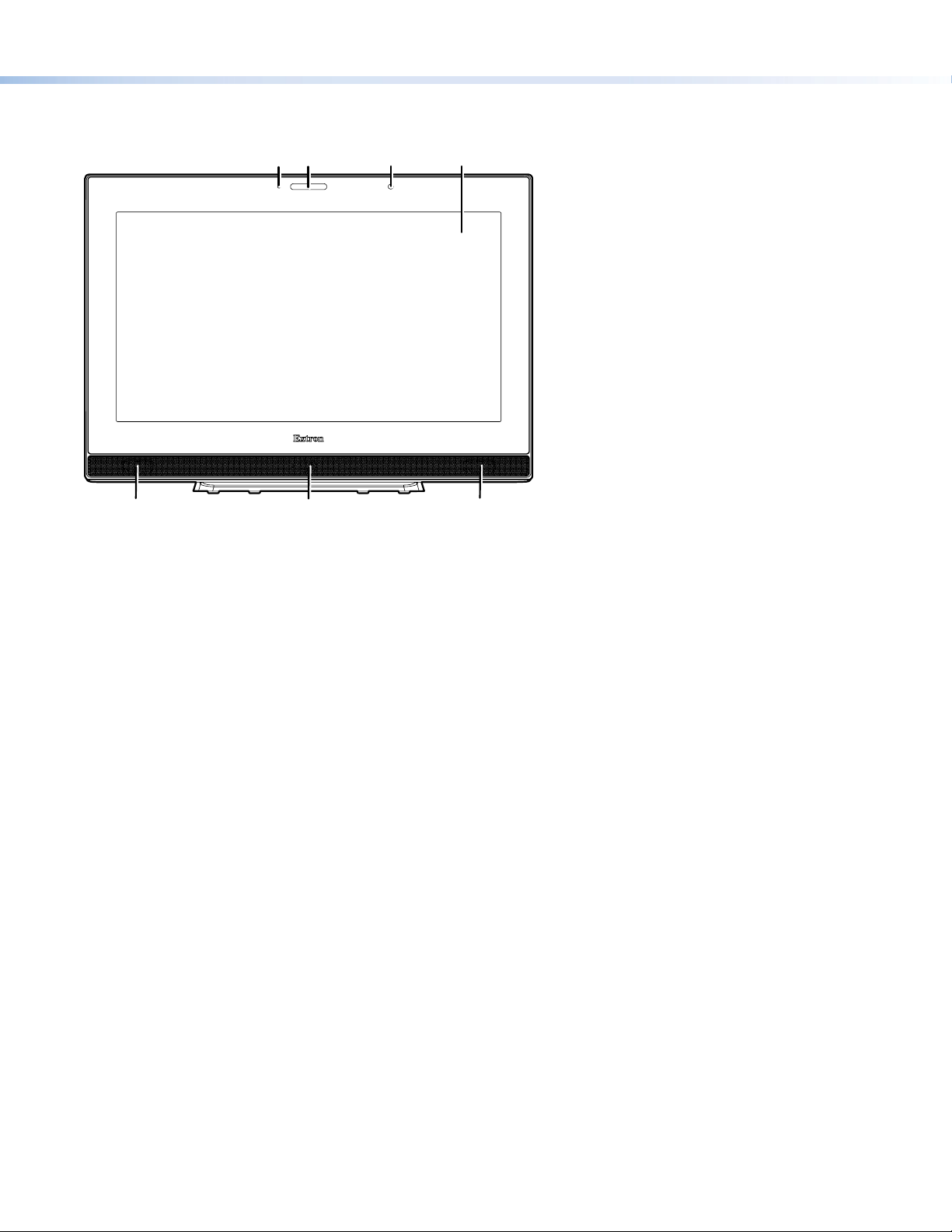
Figure 4 shows the TLP Pro 1720TG front panel diagram. The features of the TLP Pro 1220TG and TLP Pro 1520TG are very similar.
AAAB
BC
CD
D
EF
E
Figure 4. TLP Pro 1720TG Front Panel
Communication LED — Shows the conguration and connection status of the touchpanel:
A
• Unlit during normal operation.
• Blinks red if the touchpanel has been congured but is not connected to an IP Link Pro control processor.
• Lights steadily if the touchpanel has not been congured.
The indicator can be enabled and disabled, using the Setup Menu (see page 6).
Status light — can be programmed to provide system feedback. The LED light bar is located above the screen.
B
Ambient light sensor — monitors ambient light level and adjusts screen brightness.
C
Capacitive touch screen — provides simple control of AV systems:
D
• The TLP Pro 1220TG has a 12.1 inch screen with a 1280x800 resolution.
• The TLP Pro 1520TG has a 15.6 inch screen with 1366x768 resolution.
• The TLP Pro 1720TG has a 17.3 inch screen with 1920x1080 resolution.
Speakers (2) — provide stereo audio for video preview and audible feedback from button presses. They are located below the
E
screen, one on each side of the panel.
Motion sensor — detects motion in front of the touchpanel.
F
E
3
Page 4
TLP Pro 1220, 1520, and 1720TG • Setup Guide (cont’d)
F
H
G
J
F
A
H
J
Rear Panel Features
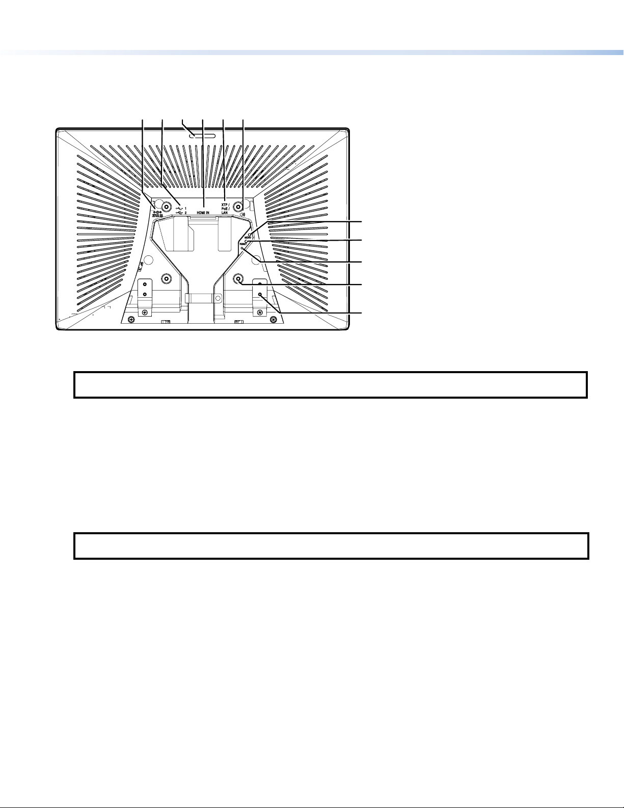
Figure 5 shows the TLP Pro 1720TG rear panel diagram (with back cover removed). The features of the TLP Pro 1220TG and
TLP Pro 1520TG are very similar.
BBBF
A
CCC
BBBF
CCC
FEEEDDDA
FEEEDDDAAA
G
G
H
H
GGG
H
H
III
J
J
KKK
III
J
J
KKK
Figure 5. TLP Pro 1720TG Rear Panel (with back cover removed)
Power supply input — connect a 12 VDC, 3.0 A Limited Power Source (LPS) power supply to this DC plug connector.
A
NOTE: The TLP Pro 1720TG ships with the Extron PI 140 power injector included. For the TLP Pro 1220TG and
TLP Pro 1520TG, either a 12 VDC, 3.0 A power supply or a power injector must be purchased separately.
USB connectors — for peripheral controls.
B
Rear status light — an LED light bar that can be programmed to provide system feedback.
C
HDMI input — for alternative video input.
D
XTP/LAN/PoE input
E
• XTP input — Connect the touchpanel to the XTP source using a twisted pair cable, terminated with an RJ-45 connector.
For complete information about which cables to use, see the user guide for your XTP product.
• LAN input — Connect the touchpanel to the LAN using a twisted pair cable, terminated with an RJ-45 connector.
• PoE input — the connector can be used with a PoE power injector. Connect the cables as shown in gure 6, which shows
the Extron PI 140 power injector (recommended by Extron).
NOTE: Some XTP models are able to remotely power these touchpanels but not all have that capability. Go to the Extron
website and check the product page for your XTP model to ensure it can power your touchpanel.
An Extron IP Link Pro control processor must also be connected to the same network as the TouchLink Pro touchpanel.
Audio output — for use with headphones or assistive listening devices.
F
Menu button — activates the setup menu and calibration screen (see Setup Menu on the following page).
G
Reset button — pressing the reset button allows the unit to be reset in any of three different modes (see Reset Modes, on the
H
following page. For more information, see the TLPPro 1220, TLPPro 1520, and TLP Pro 1720 Series User Guide).
Reset LED — provides feedback about the reset status when the user presses the reset button.
I
VESA mounting holes (4) — for use with D-type VESA mounting kits with the 100 x 100 mm mounting pattern.
J
Base attachment hinge (2) — each hinge secures the touchpanel to the base with two screws.
K
4
Page 5
XTP Device
touchpanel
Extr
Connecting Power
ATTENTION:
• The touchpanels can use a 12 VDC desktop power supply or Power over Ethernet. Do not connect either power supply
before reading the Attention in the Power section of the TLPPro 1220, TLPPro 1520, and TLP Pro 1720 Series User Guide.
• Les écrans tactiles peuvent utiliser une source d’alimentation externe 12 Vcc ou l’alimentation POE via Ethernet. Ne
branchez pas de sources d’alimentation externes avant d’avoir lu les mises en garde dans la section «PowerSupply» du
TLPPro 1220, TLPPro 1520, and TLP Pro 1720 Series User Guide.
The Extron PI 140 power injector is included with the TLP Pro 1720MG. For the TLP Pro 1220MG or TLP Pro 1520MG, a 12 VDC
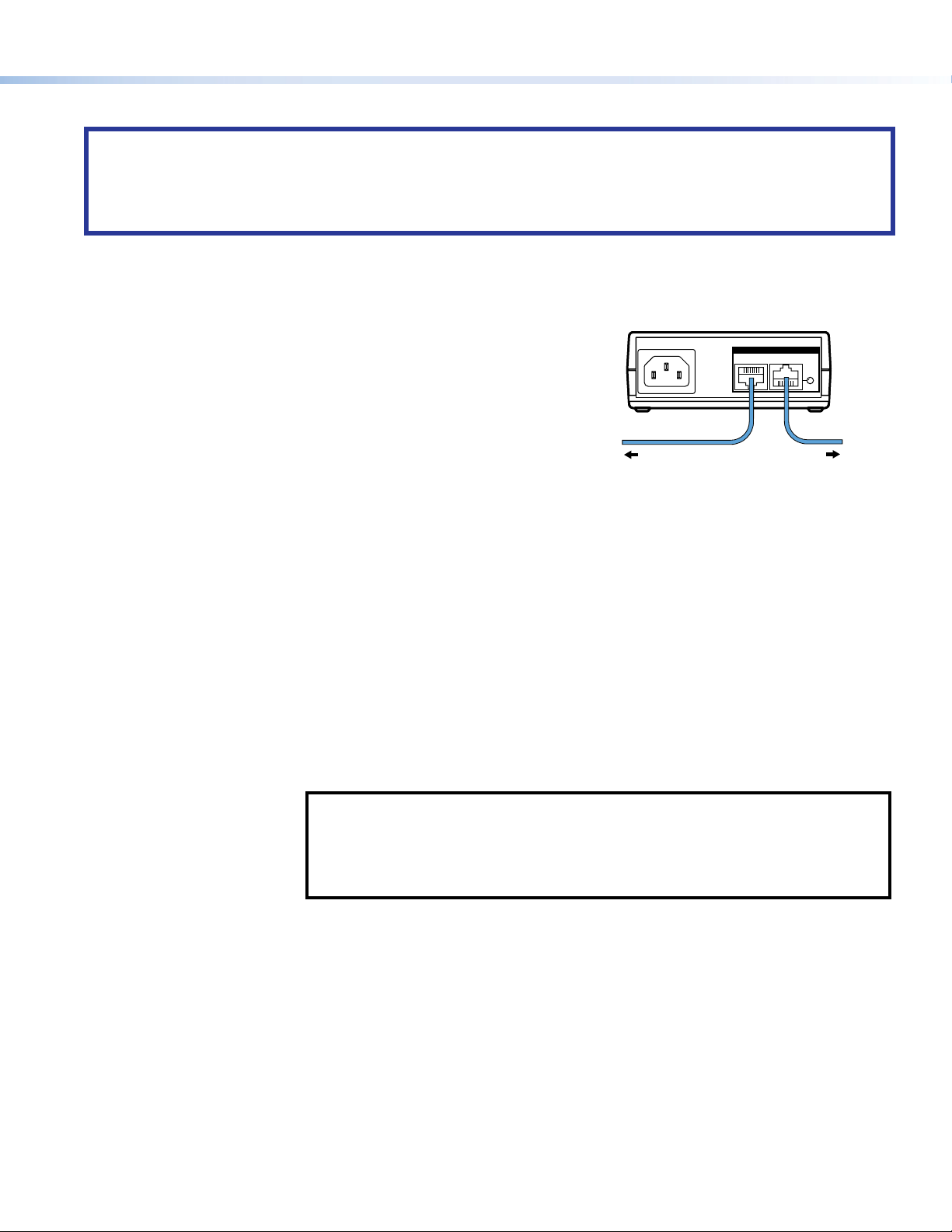
power supply or a power injector must be purchased separately. Figure 6 shows the Extron PI 140. Your power injector may look
different.
1. Connect a straight-through Ethernet cable from the power injector to a switch or router. This cable carries network information
from the switch or router to the power supply input.
2. Connect a second straight-through cable from the power injector to the TLP
Pro touchpanel XTP/LAN/PoE connector (see figure 5, E, on page 4). This
cable carries the network information and 48VDC from the power injector to
the touchpanel.
3. Connect the IEC power cord to a convenient 100 VAC to 240 VAC, 50-60 Hz
power source.
Alternatively, use an Ethernet cable to connect the XTP/LAN/PoE port of the interface to a PoE+ switch or connect the touchpanel
directly to an XTP model that is capable of remotely powering a touchpanel (see the note on page 4).
100-240V~50/60 Hz
1.1A MAX
INPUT OUTPUT
POWERED TLP
LAN
on PI 140
To Network or
Figure 6. Connecting the Power Injector
To a TLP Pro
Reset Modes: a Brief Summary
The TLP Pro 1220TG, TLP Pro 1520TG, and TLP Pro 1720TG offer the following reset modes. For full information about the modes,
see the TLPPro 1220, TLPPro 1520, and TLP Pro 1720 Series User Guide.
• Use factory firmware:
• Reset All IP Settings:
• Reset to Factory Defaults:
• Enable or Disable the
DHCP Client
Press and hold the Reset button (figure 5, H) while applying power to the unit. Use this mode
to replace rmware in the event of rmware failure.
Press and hold the Reset button for 6 seconds. After the Reset LED (I) blinks twice, release
and momentarily press the Reset button. Use this mode to reset all network settings without
affecting user-loaded les.
Press and hold the Reset button for 9 seconds. After the Reset LED blinks three times, release
and momentarily press the Reset button. Use this mode to return the interface to factory
default settings.
NOTES:
• The factory congured passwords for all accounts on this device have been set to the
device serial number. Passwords can be changed during conguration. Passwords are
case sensitive.
• If the device is reset to default settings, the passwords are reset to the default
password, which is extron (for either admin or user).
Use this mode to toggle between DHCP enabled and DHCP disabled. Press the Reset button
ve times, consecutively. After the fth press, do not press the button again within 3 seconds.
If DHCP was enabled, it is now disabled and the Reset LED blinks three times. If DHCP was
disabled, it is now enabled and the Reset LED blinks six times.
5
Page 6
TLP Pro 1220, 1520, and 1720TG • Setup Guide (cont’d)
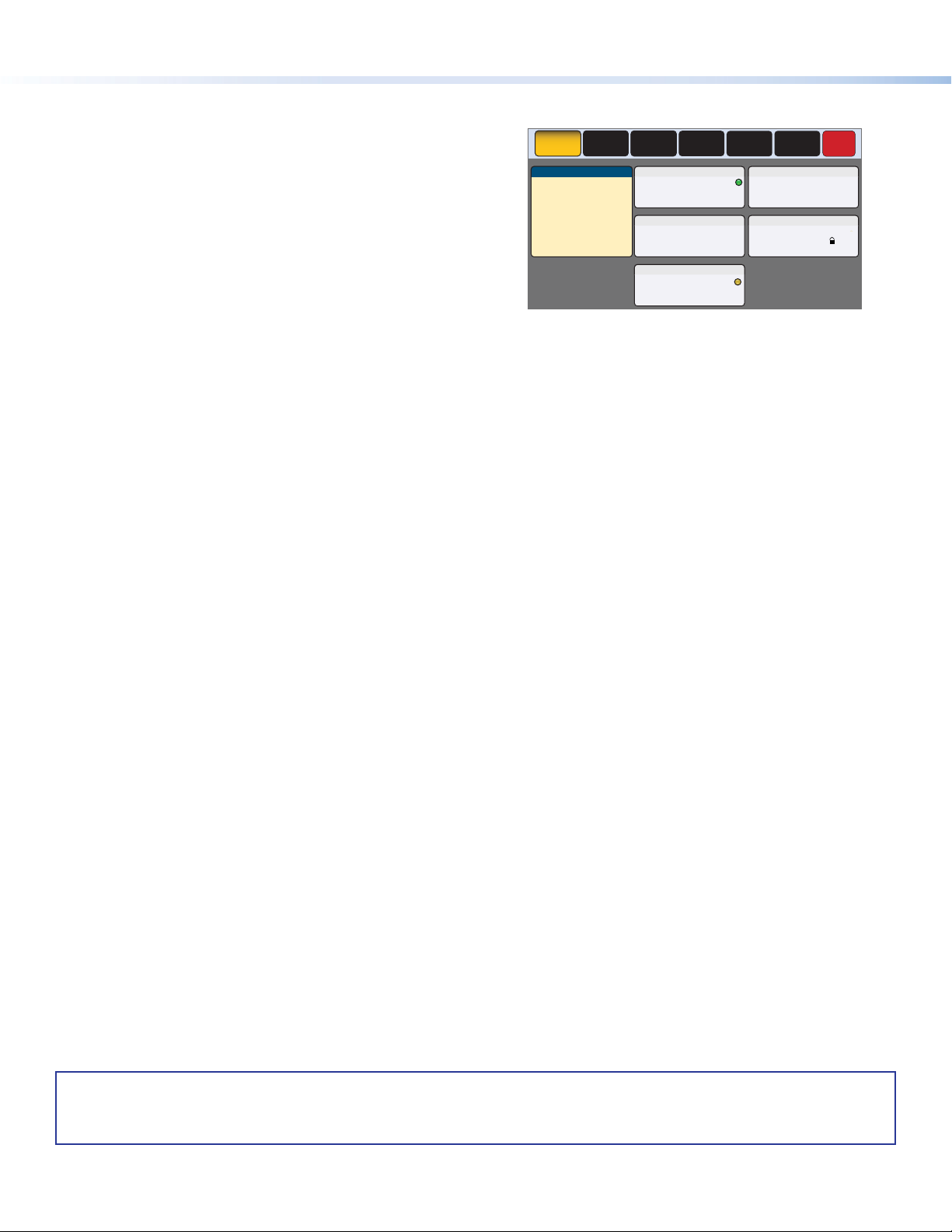
Setup Menu
Press the Menu button (figure 5, G) to open the setup menu.
Select any of the six available screens (Status, Network, Display,
Audio, Input and Advanced) by pressing the appropriate button
in the navigation bar at the top of the screen (for more information,
see the TLPPro 1220, TLPPro 1520, and TLP Pro 1720 Series User
Guide).
Figure 7 shows the setup menu for the TLP Pro 1220TG. The setup
menus for the TLP Pro 1520TG and TLP Pro 1720TG are very
similar.
Press the
Menu button for at least 3 seconds to open the calibration
screen. Follow the on-screen instructions.
Status
Network
Info
Model: TLP Pro 1220TG
Part Number:60-1341-02
Firmware
Version:
1.02.0000.b003
Bootloader
Version:
1.03.0000
PoE: Active
Display
IP Address:
DHCP:
Host Name:
Master Volume:
Master Mute: Off
Advanced
Controller IP: 192.168.254.250
Project Size: 1/197 MB
Figure 7. Setup Menu: Status page for TLP Pro 1220TG
Audio
Network
192.168.254.251
Off
TLI-AB-CD-EF
Audio
100
Advanced
Input
Resolution:
Project:
Sleep Timer:
Input
HDMI: No Signal
XTP: 1280x720
Display
1280x800
1280x800
5 Minutes
Exit
HDCP
For information on safety guidelines, regulatory compliances, EMI/EMF compatibility, accessibility, and related topics, see the
Extron Safety and Regulatory Compliance Guide on the Extron website.
For information about replacing and disposing of batteries, see the TLP Pro 1225 and TLP Pro 1525 Series User Guide at
www.extron.com.
© 2016 - 2020 Extron — All rights reserved. www.extron.com
6
Worldwide Headquarters: Extron USA West, 1025 E. Ball Road, Anaheim, CA 92805, 800.633.9876
All trademarks mentioned are the property of their respective owners.
68-2294-50 D
08 20
 Loading...