

Page 1
SF 10C SUB
Ceiling-mounted Subwoofer
User Guide
Speakers
68-2870-01 Rev. B
07 20
Page 2
Safety Instructions
Safety Instructions • English
WARNING: This symbol, , when used on the product, is intended to
alert the user of the presence of uninsulated dangerous voltage within
the product’s enclosure that may present a risk of electric shock.
ATTENTION: This symbol, , when used on the product, is intended
to alert the user of important operating and maintenance (servicing)
instructions in the literature provided with the equipment.
For information on safety guidelines, regulatory compliances, EMI/EMF
compatibility, accessibility, and related topics, see the Extron Safety and
Regulatory Compliance Guide, part number 68-290-01, on the Extron website,
www.extron.com.
Sicherheitsanweisungen • Deutsch
WARUNG: Dieses Symbol auf demProdukt soll den Benutzer darauf
aufmerksam machen, dass im Inneren des Gehäuses dieses Produktes
gefährliche Spannungen herrschen, die nicht isoliert sind und die einen
elektrischen Schlag verursachen können.
VORSICHT: Dieses Symbol auf dem Produkt soll dem Benutzer in
der im Lieferumfang enthaltenen Dokumentation besonders wichtige
Hinweise zur Bedienung und Wartung (Instandhaltung) geben.
Weitere Informationen über die Sicherheitsrichtlinien, Produkthandhabung,
EMI/EMF-Kompatibilität, Zugänglichkeit und verwandte Themen finden Sie in den
Extron-Richtlinien für Sicherheit und Handhabung (Artikelnummer
68-290-01) auf der Extron-Website, www.extron.com.
Instrucciones de seguridad • Español
ADVERTENCIA: Este símbolo, , cuando se utiliza en el producto, avisa
al usuario de la presencia de voltaje peligroso sin aislar dentro del
producto, lo que puede representar un riesgo de descarga eléctrica.
ATENCIÓN: Este símbolo, , cuando se utiliza en el producto,
avisa al usuario de la presencia de importantes instrucciones de
uso y mantenimiento estas estan incluidas en la documentación
proporcionada con el equipo.
Para obtener información sobre directrices de seguridad, cumplimiento
de normativas, compatibilidad electromagnética, accesibilidad y temas
relacionados, consulte la Guía de cumplimiento de normativas y seguridad de
Extron, referencia 68-290-01, en el sitio Web de Extron, www.extron.com.
Instructions de sécurité • Français
AVERTISSEMENT : Ce pictogramme, , lorsqu’il est utilisé sur le
produit, signale à l’utilisateur la présence à l’intérieur du boîtier du
produit d’une tension électrique dangereuse susceptible de provoquer
un choc électrique.
ATTENTION : Ce pictogramme, , lorsqu’il est utilisé sur le produit,
signale à l’utilisateur des instructions d’utilisation ou de maintenance
importantes qui se trouvent dans la documentation fournie avec
l’équipement.
Pour en savoir plus sur les règles de sécurité, la conformité à la réglementation,
la compatibilité EMI/EMF, l’accessibilité, et autres sujets connexes, lisez les
informations de sécurité et de conformité Extron, réf. 68-290-01, sur le site
Extron, www.extron.com.
Page 3

Copyright
© 2019-2020 Extron Electronics. All rights reserved. www.extron.com
Trademarks
All trademarks mentioned in this guide are the properties of their respective owners.
The following registered trademarks (®), registered service marks (SM), and trademarks (TM) are the property of RGBSystems, Inc. or ExtronElectronics
(see the current list of trademarks on the Terms of Use page at www.extron.com):
Registered Trademarks (
Extron, Cable Cubby, ControlScript, CrossPoint, DTP, eBUS, EDID Manager, EDID Minder, Flat Field, FlexOS, Glitch Free, Global Configurator,
GlobalScripter, GlobalViewer, Hideaway, HyperLane, IPIntercom, IPLink, KeyMinder, LinkLicense, LockIt, MediaLink, MediaPort, NAV,
NetPA, PlenumVault, PoleVault, PowerCage, PURE3, Quantum, ShareLink, Show Me, SoundField, SpeedMount, SpeedSwitch, StudioStation,
SystemINTEGRATOR, TeamWork, TouchLink, V-Lock, VideoLounge, VN-Matrix, VoiceLift, WallVault, WindoWall, XPA, XTP, XTPSystems, and ZipClip
Registered Service Mark
(SM)
: S3 Service Support Solutions
Trademarks (™
AAP, AFL (Accu-RATEFrameLock), ADSP(Advanced Digital Sync Processing), Auto-Image, AVEdge, CableCover, CDRS(ClassD Ripple
Suppression), Codec Connect, DDSP(Digital Display Sync Processing), DMI (DynamicMotionInterpolation), DriverConfigurator, DSPConfigurator,
DSVP(Digital Sync Validation Processing), eLink, EQIP, Everlast, FastBite, Flex55, FOX, FOXBOX, IP Intercom HelpDesk, MAAP, MicroDigital,
Opti-Torque, PendantConnect, ProDSP, QS-FPC(QuickSwitch Front Panel Controller), RoomAgent, Scope-Trigger, SIS, SimpleInstructionSet,
Skew-Free, SpeedNav, Triple-Action Switching, True4K, True8K, Vector™ 4K, WebShare, XTRA, and ZipCaddy
®
)
)
Page 4
FCC Class A Notice
This equipment has been tested and found to comply with the limits for a Class A digital
device, pursuant to part15 of the FCC rules. The ClassA limits provide reasonable
protection against harmful interference when the equipment is operated in a commercial
environment. This equipment generates, uses, and can radiate radio frequency energy and,
if not installed and used in accordance with the instruction manual, may cause harmful
interference to radio communications. Operation of this equipment in a residential area is
likely to cause interference. This interference must be corrected at the expense of the user.
NOTE: For more information on safety guidelines, regulatory compliances, EMI/EMF
compatibility, accessibility, and related topics, see the Extron Safety and Regulatory
Compliance Guide on the Extron website.
VCCI-A Notice
この装置は、クラスA情報技術装置です。 この装置を家庭環境で使用すると、電波妨害を引き
起こすことがあります。 その場合には使用者が適切な対策を講ずるよう要求されることがあります。
VCCI-A
Battery Notice
This product contains a battery. Do not open the unit to replace the battery. If the
battery needs replacing, return the entire unit to Extron (for the correct address, see the
Extron Warranty section on the last page of this guide).
CAUTION: Risk of explosion. Do not replace the battery with an incorrect type. Dispose
of used batteries according to the instructions.
ATTENTION : Risque d’explosion. Ne pas remplacer la pile par le mauvais type de
pile. Débarrassez-vous des piles usagées selon le mode d’emploi.
Page 5
Conventions Used in this Guide
Notifications
The following notifications are used in this guide:
WARNING: Potential risk of severe injury or death.
AVERTISSEMENT : Risque potentiel de blessure grave ou de mort.
CAUTION: Risk of minor personal injury.
ATTENTION : Risque de blessuremineure.
ATTENTION:
• Risk of property damage.
• Risque de dommages matériels.
NOTE: A note draws attention to important information.
TIP: A tip provides a suggestion to make working with the application easier.
Software Commands
Commands are written in the fonts shown here:
^AR Merge Scene,,0p1 scene 1,1 ^B 51 ^W^C.0
[01] R 0004 00300 00400 00800 00600 [02] 35 [17] [03]
E X! *X1&* X2)* X2#* X2! CE}
NOTE: For commands and examples of computer or device responses used in this
guide, the character “0” is the number zero and “O” is the capital letter “o.”
Computer responses and directory paths that do not have variables are written in the font
shown here:
Reply from 208.132.180.48: bytes=32 times=2ms TTL=32
C:\Program Files\Extron
Variables are written in slanted form as shown here:
ping xxx.xxx.xxx.xxx —t
SOH R Data STX Command ETB ETX
Selectable items, such as menu names, menu options, buttons, tabs, and field names are
written in the font shown here:
From the File menu, select New.
Click the OK button.
Specifications Availability
Product specifications are available on the Extron website, www.extron.com.
Extron Glossary of Terms
A glossary of terms is available at http://www.extron.com/technology/glossary.aspx.
Page 6

Page 7

Contents
Introduction............................................................ 1
About this Guide ................................................. 1
About the SF 10C SUB ...................................... 1
Features ............................................................. 2
Installation .............................................................. 4
Placement Considerations and Acoustical
Reinforcement ................................................... 4
Installation Environment .................................. 4
Acoustical Reinforcement ............................... 5
Mounting the Subwoofer .................................... 6
Suspending in the Ceiling ............................... 6
Installing Long Legs for Vertical Installation
on a Floor .................................................... 10
Installing Short Legs for Horizontal
Installation on a Floor ................................... 13
Mounting the Port Tube .................................... 13
Installing the Grille ............................................. 14
Connection and Operation ................................ 16
Connection ................................................... 16
Operational Considerations ........................... 18
Troubleshooting ................................................ 19
viiSF 10C SUB • Contents
Page 8

SF 10C SUB • Contents viii
Page 9
Introduction
• About this Guide
• About the SF 10C SUB
• Features
About this Guide
This guide describes the Extron SF 10C SUB, a subwoofer, that is typically installed above
a suspended ceiling. This guide describes how to install, operate, and configure the
subwoofer.
About the SF 10C SUB
The SF 10C SUB (see figure1 on the next page) is a plenum-rated, 8 ohm, 4th order
band-pass subwoofer with a tuned bass-reflex port. When installed, the subwoofer is
typically suspended by wire from the structural ceiling above the suspended ceiling. This
avoids unwanted rattling and vibrating in the ceiling tile grid. It features a 10-inch ported
woofer housed within a cylindrical enclosure. A right-angle port on the front of the enclosure
directs the sound waves into the listening area.
The subwoofer has a frequency range of 25 Hz to 160 Hz, -10 dB, half space.
The SF 10C SUB is compatible with any Extron low impedance amplifier with sufficient
output drive power. The unit is UL 2043 Listed for use in air-handling spaces.
The subwoofer is intended for use in a bi-amplified system. Separate amplifiers should
power the low and high frequencies.
ATTENTION:
• The SF 10C SUB is UL Listed for use in plenum airspaces: meets UL 2043 for heat
and smoke release.
• Le SF 10C SUB est certifié UL pour une utilisation dans des espaces de plenum:
il est conforme à la norme UL 2043 relative à l’évacuation de la chaleur et de la
fumée.
• Suitable for use in environmental air space in accordance with Section 300-22(C)
of the National Electrical Code, and Sections 2-128, 12-010(3) and 12-100 of the
Canadian Electrical Code, Part 1, CSA C22.1.
• The product has been additionally investigated to UL 2043, “Fire Test for Heat and
Visible Smoke Release for Discrete Products and Their Accessories Installed in AirHandling Spaces”.
• Adapté à des espaces environnementaux de plenum, conformément à la section
300-22(C) du National Electrical Code américain et aux sections 2-128, 12-010(3)
et 12-100 du Code canadien de l’électricité, Partie 1, CSA C22.1.
• Le produit est par ailleurs conforme à la norme UL 2043 « Fire Test for Heat and
Visible Smoke Release for Discrete Products and Their Accessories Installed in AirHandling Spaces ».
SF 10C SUB • Introduction 1
Page 10

Ext
SF
Pe
Spea
PC
ron
3PT
ndant
kers
Table Microphones
(Channel 1)
Audio
Microphone
Audio
(Channel 2)
OVER
12
TEMP
e
Extron
XPA U 1002-70V
Power Amplier
GREEN - ACTIVE
AMBER - STANDBY
Extron
XPA 4002
Power Amplier
ACTIVITY
EXP LAN USB
CONFIG
Audio
muteselect
Audio
LIMITER/PROTECT
SIGNAL
OVER
TEMP
INPUTS OUTPUTS
1 2 3 4 5 6 7 8 1 2 3 4 5 6 7 89 10 11 12
CLIP
SIGNAL
1
2
LIMITER / PROTECT
SIGNAL
Audio
CLIP
SIGNAL
Extron
SF 10C SUB
Subwoofer
POWER AMPLIFIERS
XPA U 1002 SERIES
(Channel 1 and 2 bridged)
Extron
DMP 128 Plus C V
Digital Matrix Processor
DMP 128 Plus
DIGITAL MATRIX PROCESSOR
USB Audio
Audio
XPA 4002
Figure 1. Typical SF 10C SUB Application
Features
• 10-inch (254 mm) low frequency driver with a tuned port — Designed specifically
for low frequency extension.
• UL 2043 rated, rigid composite enclosure — Enclosure remains out of view when
suspended above the ceiling grid.
• Frequency range: 25 Hz to 160 Hz
• 800 watts continuous program
400 watts continuous pink noise — Power capacity per IEC 60268-5
• 8 ohm operation — Direct low impedance power avoids low frequency transformer
distortion.
• Suspension mounting above the ceiling structure greatly reduces rattle —
Because the unit is physically isolated from the ceiling grid, low frequency vibrations are
not transferred to loose structural components.
• 4th order bandpass enclosure design — High output with controlled and clean low
frequency extension
• No crossover needed when used with SF 26CT, SF 3C LP, or SF 3CT LP ceiling
speakers — Eliminates phase problems at a crossover point.
SF 10C SUB • Introduction 2
Page 11

• Includes installation and suspension hardware — Four sets of 15-foot (4.6 m)
steel cables with locking adapters are used to raise the SF 10C SUB into place and
suspend it.
• Includes C-ring and paintable grille — Port output into the room blends in with
ceiling speakers.
• Paintable enclosure — The SF 10C SUB enclosure can be painted with a plastic-
friendly paint.
• Integrated flame arrester for safety — Restricts flammability for plenum installations.
• Optional floor mounting kit — The SMK F SF 10C Plus kit provides legs for both
vertical and horizontal mounting of the SF 10C SUB to a solid surface.
• 5-year parts and labor warranty
SF 10C SUB • Introduction 3
Page 12

Installation
This section describes the installation and the operation of the SF 10C SUB, including:
• Placement Considerations and Acoustical Reinforcement
• Mounting the Subwoofer
• Mounting the Port Tube
• Installing the Grille
• Connection and Operation
• Troubleshooting
Placement Considerations and Acoustical Reinforcement
Installation Environment
Ceiling placement
• The speaker is rated for installation in plenum spaces.
• The mounting kit comes with four sets of aircraft cables and cable gripper mounting
hardware for suspending the speaker in a horizontal orientation.
• Mounting holes for mounting using unistruts or all thread rods are provided.
• Isolation grommets are provided that dampen mechanical vibrations from the
subwoofer to the rest of the structure.
• Other than the isolation grommets, the installer must provide the mounting
hardware for unistrut or all thread rod installation.
• The mounting holes can also accept hanger wire.
• The port tube does not isolate the listening space from the installation space.
Bleed-over into adjacent rooms must be taken into consideration.
Placement behind a wall
• When the subwoofer is installed behind a wall, the port tube must be located as close
to the wall surface facing the listening space as possible.
• The drywall facing the subwoofer may need to be removed between the studs on either
side of the unit, in order to bring the port tube as close as possible to the front surface
of the wall. In this case, fire blocks must be run in-between the studs, to seal off the
space above the removed portion of the wall.
• The optional SMK F SF 10C Plus floor mounting kit must be used when the subwoofer
is placed on the floor and must be strapped to a stud.
SF 10C SUB • Installation 4
Page 13

Acoustical Reinforcement
Depending on where you mount the subwoofer, such as next to a large, rigid, planar
surface, you can achieve some level of acoustical reinforcement (see figure2).
NOTE: At the frequencies at which the subwoofer operates, fiberglass ceiling tiles are
acoustically transparent and offer little acoustical reinforcement.
Corner Mounting
(π/2)
Ceiling Mounting
(2π)
Edge Mounting
(π)
Free Mounting
(4π)
Figure 2. Mounting Locations with Regards to Acoustical Reinforcement
SF 10C SUB • Installation 5
Page 14

• Corner mounting (see figure2 on the previous page) — The subwoofer is mounted
in a corner of a surface where three surfaces meet, giving reinforcement from all three
surfaces. This option provides the most reinforcement. The port tube should be as close
to the corner as possible for best results.
• Edge mounting (figure2) — The subwoofer is mounted at the edge of a surface
where two surfaces meet, giving reinforcement from both surfaces. This option is as
much as 6 dB less sensitive than corner mounting. The port should be as close to the
wall as possible for best results.
• Ceiling, wall, or floor mounting (figure2) — The subwoofer is mounted in or on a
surface in an area away from any other surface. This option is as much as 12 dB less
sensitive than corner mounting. There is reinforcement from only one surface.
• Free mounting (figure2) — The subwoofer is mounted away from all walls, the floor
and the ceiling. This option is as much as 18 dB less sensitive than corner mounting.
There is no reinforcement from any surface.
Mounting the Subwoofer
The SF 10C SUB can be suspended in a ceiling or rested on the floor.
Suspending in the Ceiling
WARNING:
AVERTISSEMENT :
• Properly suspending equipment requires training and expertise. Improper rigging of
suspended equipment can cause the speaker to fall, resulting in death, personal
injury, equipment damage, and legal liability. Installation must be carried out by fully
qualified installers, in accordance with all required safety codes and standards at
the place of installation.
• Il est indispensable de disposer de compétences techniques pour pouvoir
suspendre l’équipement. Une manipulation incorrecte de l’équipement suspendu
peut provoquer la chute de l’enceinte, entraînant la mort, des lésions corporelles,
des dégâts matériels, et engageant la responsabilité d’un individu. L’installation
doit être effectuée par des installateurs hautement qualifiés, conformément à
l’ensemble des codes et des normes de sécurité réglementaires sur le lieu de
l’installation.
• The legal requirements for suspending equipment vary from country to country.
Extron strongly recommends that you consult your local safety standards office
before installing any product. Extron also recommends that you thoroughly check
any laws and bylaws prior to installation.
• Les conditions juridiques relatives à la suspension d’équipements varient de pays
en pays. Extron vous recommande vivement de consulter les standards de sécurité
en vigueur dans votre pays avant d’installer un produit. Extron vous recommande
également de vérifier minutieusement toute loi et tout règlement avant l’installation.
SF 10C SUB • Installation 6
Page 15

ATTENTION:
beyond the edge of ceiling tile.
• Installation and service must be performed by authorized personnel only.
• L’installation et l’entretien doivent être effectués par le personnel autorisé
uniquement.
• This unit must be repaired by personnel trained by Extron or returned to Extron for
repair.
• Cette unité doit être réparée par un technicien formé par Extron ou renvoyée à
Extron pour réparation.
The subwoofer can be suspended using the included aircraft cables (see “Aircraft cable
installation”) or, optionally, with threaded rods acquired locally (see Threaded rod
installation on page10).
Aircraft cable installation
Suspend the subwoofer above a false ceiling using the included aircraft cables as follows:
Remove ceiling tile and install suspension cables.
For installation with optional threaded rods, see Threaded rod installation.
1. Determine where the subwoofer is to be suspended and its orientation above the
suspended ceiling.
NOTE: Remember that the sound from the unit is directed out the port. Therefore,
although you can suspend the subwoofer in any horizontal orientation, the port
needs to be pointed into the listening space.
Consider the following as you make this determination:
• Possible acoustical reinforcement (see Acoustical Reinforcement on page5).
• The size (length, width, and height) of the subwoofer.
• The desired location of the woofer port. Ensure that the center of the port tube will
be at least 5-3/16 inches (13.7 cm) from the edge of suspended ceiling tile once
that tile is installed.
NOTE: This positioning ensures that the grille adapter and C-ring fit properly
once installed (see figure3).
Do not install the C-ring
Figure 3. Grille Adapter and C-ring Fit
• Any obstructions above the suspended ceiling that could constrain the orientation
of the suspended subwoofer.
SF 10C SUB • Installation 7
Page 16
2. At the location where the subwoofer is to be installed, remove as many ceiling tiles as
necessary to install the subwoofer.
NOTE: The number of tiles to remove depends on the height of the structural
ceiling above the suspended ceiling, given the 10-degree spread from the
subwoofer to the structural ceiling.
At an approximate angle of 10 degrees out from each corner of
where the subwoofer will be installed, mark and drill four holes in the
structural ceiling for the suspension cable anchors.
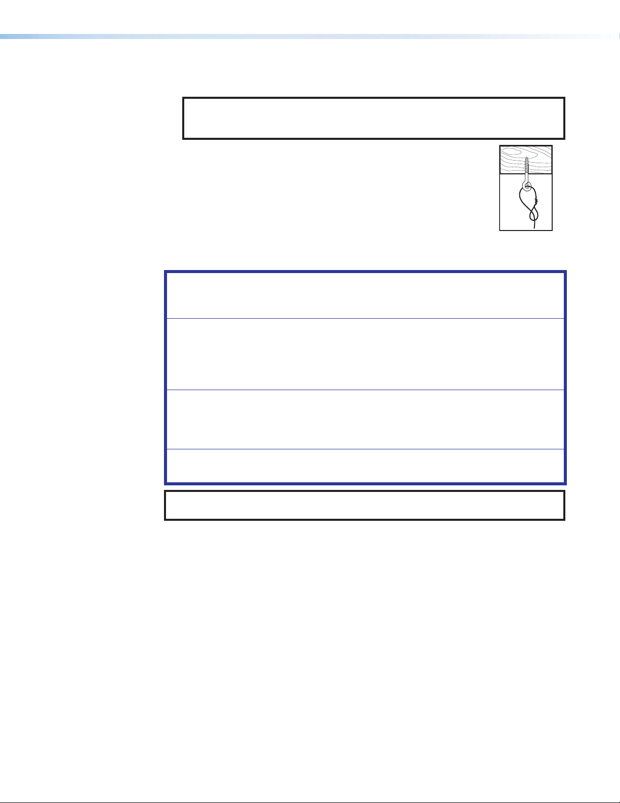
3. Screw a lag eye bolt (or an appropriate anchor) into each hole.
4. Thread the loose end of the suspension cable through the bolt eyehole,
pass the loose end of the cable through the looped end and tighten.
Allow each cable to hang.
Suspend the main subwoofer enclosure from the ceiling
ATTENTION: The SF 10C SUB is heavy, approximately 38 pounds (17 kg), and bulky.
ATTENTION : La SF 10C SUB est lourde, et pèse environ 17 kg (38 livres), et est
volumineuse.
• Use at least two people to install the subwoofer; one person to lift the unit into
position AND to hold it, the second person to fasten the suspension cables.
• Il faut au minimum deux personnes pour installer le caisson de grave ; la première
pour mettre l’unité en place ET la tenir, et la seconde pour raccorder les câbles de
suspension.
• Consider using a scissor-lift or other lifting apparatus rather than a ladder to work
in the ceiling.
• Songez à utiliser une nacelle élévatrice ou tout équipement similaire plutôt qu’une
échelle pour travailler au plafond.
• Do not rest the subwoofer on the ceiling grid, even temporarily.
• Ne posez pas le caisson de grave sur la grille de plafond, même temporairement.
TIP: If a scissor-lift is not available, the speaker can be hoisted using the suspension
cables.
1. Remove the grommets from all four corners of the subwoofer frame (see figure4 on
the next page).
2. Install the included eyebolts into the four holes on the four corners of the subwoofer
frame. Secure the eyebolts in place with the provided locking nuts (figure4).
3. With the help of at least one other person, carefully lift the subwoofer enclosure into the
installation location.
4. Holding a cable gripper, pass the loose end of one of the cables down through one hole
of the gripper. Ensure that about 12 to 15 inches (30 to 38 cm) of cable has exited the
gripper (figure4).
SF 10C SUB • Installation 8
Page 17

WARNING:
e
AVERTISSEMENT :
• Maintain at least a 2-inch (5 cm) clearance between the plunger on the cable
gripper and any other object in the ceiling space. This includes the space
between the eyebolt below the gripper and the mounting hardware above the
gripper. If an object strikes the plunger, the cable gripper could disengage and
allow the subwoofer to fall.
• Conservez au minimum 5 cm (2") d’espace libre entre le piston sur le serre-
câble et tout autre objet se trouvant dans l’espace plafond. Il s’agit de l’espace
entre l’anneau de levage sous le serre-câble et le matériel de montage audessus du serre-câble. Si un objet heurte le piston, le serre-câble pourrait se
desserrer et entraîner la chute du caisson de basses.
Thread the cable down through the cable gripper, through the ey
≥2"
(50 mm)
(50 mm)
of one of the eyebolts, and back up through the lock.
≥1"
(25 mm)
Cable
≥2"
Gripper
Plunger
Eyebolt
Countersunk
Washer
Locking Nut
(not shown)
Figure 4. Installing the Subwoofer with the Included Steel Cables
5. Pass the loose end of the cable through the eye of one of the eye bolts on the
subwoofer enclosure and then through the other hole in the cable gripper. Ensure that
at least 1 inch (25 mm) of cable comes through the other end of the gripper.
6. Repeat steps 4 and 5 for each corner.
SF 10C SUB • Installation 9
Page 18
7. Adjust the cable tension through all cable grippers so that the subwoofer appears level
rods through holes
on the ends of the
to the critical eye and to ensure that its bottom brackets will be approximately 1 inch
(2.5 cm) from the top surface of suspended ceiling tile once that tile is installed.
NOTE: The exact height of the subwoofer is not critical at this point. You will make
final adjustments after the grille is installed.
Threaded rod installation
Secure the subwoofer to the structural ceiling using threaded rods as follows:
NOTES:
• Extron recommends 1/4-inch or 3/8-inch diameter threaded rods for installing this
product.
• The threaded rod must be properly secured to the ceiling structure. For example,
properly fasten a unistrut to the ceiling structure and attach threaded rods using
nuts and fender washers.
1. Fasten four threaded rods to the support structure.
Extron recommends fastening the rods to unistruts,
one over each corner of the subwoofer installation
location.
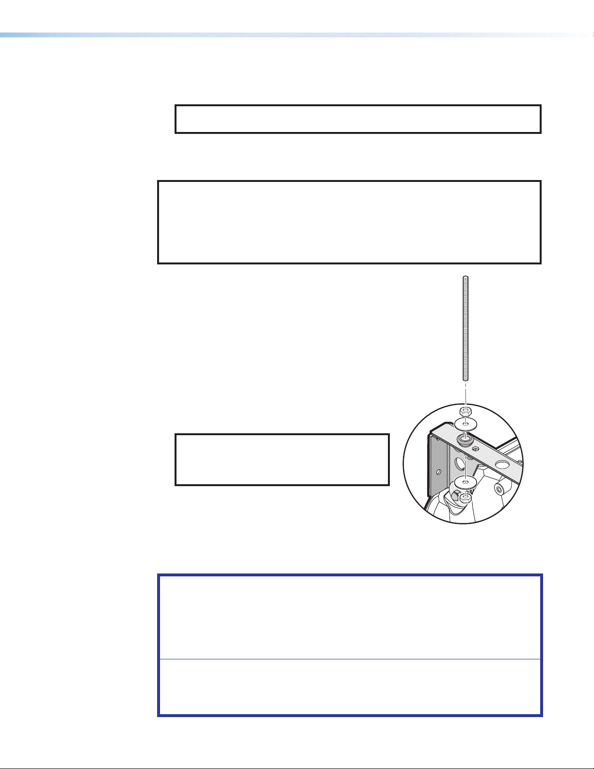
2. Fasten a rod to each corner securing point of the
subwoofer with nuts and fender washers
(see the figure at right).
3. Adjust all the nuts that secure the subwoofer to the
ceiling so that the subwoofer appears level to the
critical eye and to ensure that its bottom brackets
will be approximately 1 inch (2.5 cm) from the top
surface of suspended ceiling tile once that tile is
installed.
Insert threaded
mounting bracket.
NOTE: The exact height of the subwoofer
above the ceiling is not critical at this point.
You will make final adjustments after the grille
is installed.
Attach washer and nut and secure.
Installing Long Legs for Vertical Installation on a
Floor
ATTENTION:
• The SF 10C SUB must have firebreaks installed in the wall, above and below it,
when it is protruding through a wall, to meet UL requirements.
• Le SF 10C SUB doit disposer de systèmes coupe-feu installés au mur, au-dessus
et au-dessous de l’unité, lorsqu’elle est placée en saillie du mur, afin de satisfaire
les exigences de l’UL.
• The subwoofer must be securely fastened to the stud or other stationary surface
when mounted in one of the vertical positions.
• En position verticale, le caisson de basses doit être solidement fixé au montant ou
à une autre surface stationnaire.
SF 10C SUB • Installation 10
Page 19

The subwoofer can be set vertically on a floor using the optional SMK F SF 10C Plus floor
2
2
1
mounting kit, as follows:
1. Determine where the subwoofer is to be placed and its orientation (port tube on top or
port tube on the bottom).
NOTES:
• Remember that the sound from the unit is directed out the port. Therefore, the
port needs to be pointed into the listening space.
• To ensure that the Extron grille fits fully into any masking wall or other partition,
the center of the port tube must be at least 5-3/16 inches (13.7 cm) from the
edge of the wall.
• The grille does not fit if you install the legs on the subwoofer with the port tube
down. Consider fabricating a small platform to lift the subwoofer or otherwise
design your own way to dress the installation to give your installation a finished
look.
• Steps 4, 5, 6, and 9 are only necessary if you are installing the subwoofer in an
adjoining space.
2. Remove the grommets from the holes in the installation bracket.
3. Fasten two legs to each installation bracket using the provided screws and locking nuts,
two on one side of the foot (see figure5, 1), and one on the other side (2).
2
2
111
Figure 5. Installing a Floor Mounting Kit
4. When installing in an adjoining space — On the far side of the wall (outside the
listening space), remove enough wall material so that the subwoofer port tube can be
placed as close to the wall (facing the listening space) as possible.
5. When installing in an adjoining space — On the near side of the wall (inside the
listening space), using the included grille cut-out template, mark where the center of the
port tube faces the installation surface. The center mark must be at least 5-3/16 inches
6. When installing in an adjoining space — On the near side of the wall (inside the
7. Place the subwoofer in the desired location.
(13.2 cm) from the edge of the installation surface (see figure3 on page7) if the
grille will be used (see Installing the Grille on page14).
listening space), mark and cut the hole in the surface.
2
2
1
1
SF 10C SUB • Installation 11
Page 20

8. Use the included nylon straps and included accessories, or locally-obtained perforated
333
metal hanger straps, to secure two of the mounting holes on the top bracket to the
nearest stud or other stationary surface (see figure6, 1). Use locally obtained hardware
suitable for the material to which the unit is being secured.
Listening Space
Installation Location
(Adjoining Space)
3
3
22222
Bracket
Screw
Lock
Nut
Nylon
Strap
Washers (2)
11111
Figure 6. Securing the Floor-mounted Subwoofer and Installing Fire Breaks
9. When installing in an adjoining space — Ensure that there are fire breaks above and
below the port tube (2) to meet UL requirements. Fabricate them if necessary.
SF 10C SUB • Installation 12
Page 21

Installing Short Legs for Horizontal Installation on a Floor
Scr
The subwoofer can be set horizontally on a floor using the optional SMK F SF 10C Plus floor
mounting kit, as follows:
1. Fasten a foot to each installation bracket using the provided screws and locking nuts.
Locking Nuts
ew
Figure 7. Short Leg Installation
2. Place the subwoofer in the desired location.
Mounting the Port Tube
1. Orient the port tube so that it is pointed into the listening space.
Mounting Screws
(4 places)
Figure 8. Installing the Port Tube
2. Using the included hardware, mount the port tube to the speaker (see figure8).
SF 10C SUB • Installation 13
Page 22

Installing the Grille
NOTE: For ceiling tile installation, if the ceiling tile is not removed for the subwoofer
1. If not already accomplished, on the installation surface, mark where the center of the
2. If not already accomplished, using the included grille cut-out template, mark and cut the
3. For ceiling tile installation, replace the ceiling tile in the grid.
4. Place the C-ring on the subwoofer side of the installation surface and center it over the
5. Place the grille adapter on the opposite side of the installation surface (see figure9) and
installation, remove it.
port tube faces the installation surface. The center mark must be at least 5-3/16 inches
(13.2 cm) from the edge of the installation surface.
hole in the surface.
hole.
use a Phillips screwdriver to turn the three locking arms to loosely mate the adapter to
the C-ring.
Locking Arms
Figure 9. Installing the Grille Adapter
6. Rotate the C-ring and grille adapter so that the locking arms do not collide with the
subwoofer.
7. Use a Phillips screwdriver to tighten the three locking arms to clamp the adapter to the
C-ring.
SF 10C SUB • Installation 14
Page 23
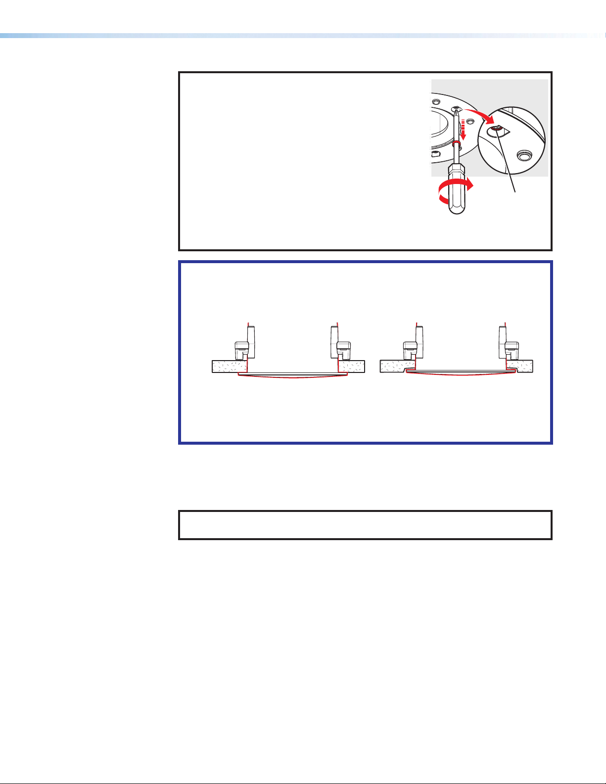
NOTE: For installation in rigid vs. soft material:
X
• Rigid material — Three locking arm screws use
built-in Opti-Torque indicator rings that snap and
separate from their plastic rings when the screws
are tightened to the correct torque. The indicator
ring falls down the screwdriver shaft. When
this occurs, stop tightening the screw to avoid
overtightening the locking arms to the C-ring (see
the figure at right).
• Soft material — Because fiberglass ceilings and
other soft materials are not as rigid as mineral tiles
and other hard materials, the Opti-Torque indicator
should not be used as a tightening guide due to the risk of overtightening. See
the ATTENTION below.
ATTENTION:
• To avoid damaging or deforming soft ceiling material, tighten the locking arms
to secure the grille adapter, but short of causing the grille adapter to deform
the flat mounting surface of the ceiling.
Opti-Torque Ring
• Afin de ne pas endommager ni altérer un plafond souple, serrez les bras de
verrouillage pour sécuriser l’adaptateur en grille, en veillant cependant à ce
que l’unité ne cause l’altération de la surface de montage plane du plafond,
comme illustré ci-dessous.
8. Affix the metal grille to the magnetic grille adapter.
9. Adjust the position of the subwoofer relative to the installation so that the subwoofer
appears level to the critical eye and is centered over the grille. Ensure that the port
tube is as close as possible to the installation surface without touching it.
NOTE: Do not allow the port tube or any part of the subwoofer to touch the
installation surface. Undesired audio vibrations can occur.
SF 10C SUB • Installation 15
Page 24

Connection and Operation
Cable Conduit
Access Plate
Connection
NOTES:
• Pair the 8-ohm subwoofer with an amplifier that outputs up to 800 watts at
8 ohms.
• Consider the distance between the subwoofer and the amplifier and whether
doubling up the speaker cable (see figure12 on page18) is necessary to
reduce the power losses through the wires.
• Avoid audio clipping:
• Ensure that the audio source does not clip the input stage of the amplifier
(check the specifications of the amplifier)
• Ensure that the audio signal does not clip the output stage of the amplifier
(check the limiter or protection indicators on the amplifier).
• Apply a limiter to the amplifier channel that drives the SF 10C SUB.
• No crossover is needed when the subwoofer is used with SF 26CT, SF 3C LP, or
SF 3CT LP ceiling speakers.
Configure the cable conduit access plate and captive screw connector as follows:
1. Loosen the cable conduit access plate screw and remove the plate before wiring the
subwoofer (see figure10).
Screw
Alternate
Knockout
Figure 10. Removing the Cable Conduit Access Plate
2. Configure the cable conduit access plate, using either of the following methods:
• When not using flexible conduit: Route the speaker wires through the cable
clamp (see figure11, 1, on the next page).
• When using flexible conduit: Remove the cable clamp and install the flexible
conduit into the plate opening. Secure the flexible conduit to the plate with the
locking nut and pull the speaker wires out through the flexible conduit (2).
SF 10C SUB • Installation 16
Page 25

NOTE: The cable conduit access plate has an alternate hole that is available by
Cable
Clamp
removing the knockout.
1
333
— OR —
2
3
Flexible
Conduit
Adapter
Figure 11. Connection Using a Cable Clamp or Flexible Conduit
3. Strip 3/16 inch (5 mm) of the cable insulation from the wire ends.
NOTES:
• The length of exposed wires is important. The ideal length is 3/16 inch (5 mm).
• If the stripped section of wire is longer than 3/16 inch, the exposed wires
may touch, causing a short circuit.
• If the stripped section of wire is shorter than 3/16 inch, wires can be easily
pulled out even if tightly fastened by the captive screws.
• Do not tin the leads before installing them in the connector. Tinned wires are
not as secure in the connector and could be pulled out.
SF 10C SUB • Installation 17
Page 26

4. Connect four or two speaker wires to the captive screw connector, as shown by the
Subwoofer
+
Double Wiring
+
following two methods (see figure12).
Using two 12 AWG wires yields
effective 9 AWG wiring, reducing
cable losses.
(Red)
(Black)
Power Amplifier
––+
Subwoofer
Single Wiring
(Red)
(Black)
––+
Power Amplifier
Figure 12. Subwoofer Wiring Methods
Wire Gauge Table
Number of Wires
per Pole
Maximum
Wire Gauge
1 12 AWG
2 16 AWG
4 18 AWG
Maximum Recommended Cable Length Table
Gauge
Cable Length
12 AWG doubled (effectively 9 AWG) 253 feet (77 m)
14 AWG doubled (effectively 11 AWG) 159 feet (48 m)
12 AWG single 126 feet (38 m)
16 AWG doubled (effectively 13 AWG) 100 feet (30 m)
14 AWG single 80 feet (24 m)
18 AWG doubled (effectively 15 AWG) 63 feet (19m)
16 AWG single 50 feet (15 m)
18 AWG single 32 feet (9 m)
ATTENTION:
• Do not tin the wire leads before installing into the connector. Tinned wires are
not as secure in the connector and could be pulled out.
• Ne pas étamer les conducteurs avant de les insérer dans le connecteur. Les
câbles étamés ne sont pas aussi bien fixés dans le connecteur et pourraient
être retirés.
5. Insert the captive screw plug into the four-pole receptacle of the subwoofer (see
figure11, 3, on the previous page) and screw it into place.
6. Replace the access plate and tighten the retaining screw.
7. Tighten the cable clamp if it was used.
Operational Considerations
Play content that you are familiar with through the system and verify that it sounds as
expected.
• Set the gain structure through the audio system appropriately.
• Set the gain on the subwoofer and speakers such that they are at the same sound
pressure level.
• If any distortion is heard, you may be driving the subwoofer too hard and may need to
add additional subwoofers to the system to get the desired sound pressure level.
SF 10C SUB • Installation 18
Page 27

Troubleshooting
Symptom Description Solution
A “chuffing” sound
is coming from the
subwoofer.
Distortion due
to port tube
placement
Distortion due
to overdriven
subwoofer
Check the placement of the port
tube. Move the tube opening slightly
away from the grille surface to reduce
distortion.
This reduces the output level
slightly, a trade-off that must be
managed.
Attenuate the signal to the subwoofer.
If the desired sound pressure level
cannot be achieved at the new setting,
consider relocating the subwoofer
to a more favorable location (for
example, edge or corner mounting —
see Acoustical Reinforcement on
page5) and swapping fiberglass
tiles (if used) for mineral tiles.
If the desired sound pressure level still
cannot be met, then the listening space
requires more subwoofers.
SF 10C SUB • Installation 19
Page 28
Extron Warranty
Extron Electronics warrants this product against defects in materials and workmanship for a period of three years
from the date of purchase. In the event of malfunction during the warranty period attributable directly to faulty
workmanship and/or materials, Extron Electronics will, at its option, repair or replace said products or components,
to whatever extent it shall deem necessary to restore said product to proper operating condition, provided that it is
returned within the warranty period, with proof of purchase and description of malfunction to:
USA, Canada, South America,
and Central America:
Extron Electronics
1230 South Lewis Street
Anaheim, CA 92805
U.S.A.
Europe:
Extron Europe
Hanzeboulevard 10
3825 PH Amersfoort
The Netherlands
Africa:
Extron South Africa
3rd Floor, South Tower
160 Jan Smuts Avenue
Rosebank 2196, South Africa
This Limited Warranty does not apply if the fault has been caused by misuse, improper handling care, electrical
or mechanical abuse, abnormal operating conditions, or if modifications were made to the product that were not
authorized by Extron.
NOTE: If a product is defective, please call Extron and ask for an Application Engineer to receive an RA (Return
Authorization) number. This will begin the repair process.
USA: 714.491.1500 or 800.633.9876 Asia: 65.6383.4400
Europe: 31.33.453.4040 or 800.3987.6673 Japan: 81.3.3511.7655
Africa: 27.11.447.6162 Middle East: 971.4.299.1800
Asia:
Extron Asia Pte Ltd
135 Joo Seng Road, #04-01
PM Industrial Bldg.
Singapore 368363
Singapore
China:
Extron China
686 Ronghua Road
Songjiang District
Shanghai 201611
China
Japan:
Extron Electronics, Japan
Kyodo Building, 16 Ichibancho
Chiyoda-ku, Tokyo 102-0082
Japan
Middle East:
Extron Middle East
Dubai Airport Free Zone
F13, PO Box 293666
United Arab Emirates, Dubai
Units must be returned insured, with shipping charges prepaid. If not insured, you assume the risk of loss or damage
during shipment. Returned units must include the serial number and a description of the problem, as well as the
name of the person to contact in case there are any questions.
Extron Electronics makes no further warranties either expressed or implied with respect to the product and its quality,
performance, merchantability, or fitness for any particular use. In no event will Extron Electronics be liable for direct,
indirect, or consequential damages resulting from any defect in this product even if Extron Electronics has been
advised of such damage.
Please note that laws vary from state to state and country to country, and that some provisions of this warranty may
not apply to you.
Contact Information
Worldwide Headquarters: Extron USA West, 1025 E. Ball Road, Anaheim, CA 92805, 800.633.9876
 Loading...