

Page 1

IMPORTANT:
installation instructions,
specifications bef
oduct to the po
ore connecting the
wer source.
Quantum Ultra® Videowall Processor • Setup Guide
Go to www.extron.com for the complete
user guide,
pr
The Extron Quantum Ultra 610 and 305 Videowall Processors are modular 4K video processors that support ultra-high resolutions
up to 2560x1600 and 4096x2160 (4K) on inputs and outputs. One processor can support multiple videowalls with mixed
resolutions and screen orientations. They also provide customizable output resolutions, edge blend compensation, input and
output image rotation, and mullion compensation for compatibility with most display technologies. USB, RS-232, and Ethernet
interfaces provide direct connections for control systems.
The Quantum Ultra 610 is a 6U, 10-slot card frame, while the Quantum Ultra 305 is a 3U frame with 5 card slots. Each input
card contains four HDMI connectors. The output cards contain either four HDMI or four DTP outputs. Both chassis support
any combination of input and output cards. Additional inputs and outputs can be added to a system with use of one or more
additional chassis.
The Extron Videowall Conguration Software (VCS), which can be downloaded from the Extron website at no cost, provides a
means of conguring videowall displays and saving window presets.
NOTE: For full installation, configuration, and operation details, see the Quantum Ultra User Guide, available at
www.extron.com.
Rear Panel Features and Connections
Quantum Ultra Rear Panel
NOTE: Figure 1 shows the rear panel of a Quantum Ultra 610. The Quantum Ultra 305 has the same rear panel connectors
except that it is 3U high, and has only five card slots and no secondary power connector.
and
Quantum Ultra 610
AA
BB
QUANTUM ULTRA 610
100-240V ~ --A MAX 50-60 Hz100-240V ~ --A MAX 50-60 Hz
DISCONNECT POWER
CORD BEFORE
SERVICING
SYSTEM REMOTE
POWER LAN
AB
RS-232
CONFIG
Tx Rx G
INPUTS
SLOT 1
INPUTS
SLOT 2
INPUTS
SLOT 3
INPUTS
SLOT 4
INPUTS
SLOT 5
OUTPUTS
SLOT 6
OUTPUTS
SLOT 7
OUTPUTS
SLOT 8
OUTPUTS
SLOT 9SLOT 10
OUTPUTS
1234
1234
1234
1234
1234
1234
1234
1234
DTP POWER
12V
4A MAX
DTP POWER
12V
4A MAX
SIGLINK
OUT 1
SIGLINK
OUT 1
OVER TP
TxRx RxGTx
OVER TP
TxRx RxGTx
SIGLINK
OUT 2
SIGLINK
OUT 2
OVER TP
TxRx RxGTx
OVER TP
TxRx RxGTx
SIGLINK
OUT 3
SIGLINK
OUT 3
OVER TP
TxRx RxGTx
OVER TP
TxRx RxGTx
SIGLINK
OUT 4
SIGLINK
OUT 4
TxRx RxGTx
TxRx RxGTx
OVER TP
OVER TP
QUANTUM IN4HDMI
QUANTUM IN4HDMI
QUANTUM IN4HDMI
QUANTUM IN4HDMI
QUANTUM IN4HDMI
QUANTUM OUT4HDMI
QUANTUM OUT4HDMI
QUANTUM OUT4HDMI
QUANTUM OUT4DTP
HDBT
DTP
QUANTUM OUT4DTP
HDBT
DTP
II
Primary AC power connector
A
Redundant AC power connector (Quantum Ultra 610 only)
B
Power switch
C
HDMI Out system output connector
D
USB system connectors
E
Figure 1. Quantum Ultra 610 Rear Panel
Primary AC power connector — Connect AC power to this IEC connector for the primary power supply.
A
Redundant power connector (Quantum Ultra 610 only) — (Optional) Connect a second AC power source to this IEC
B
USB Config control connector
F
RS-232 control connector
G
LAN connectors A and B
H
Input and output card slots
I
connector for the secondary power supply to provide uninterrupted operation in the event of failure of the primary supply.
1
Page 2
Quantum Ultra • Setup Guide (Continued)
Power switch — Press the bottom of this momentary rocker switch to power the unit off and on.
C
z If the unit is off, pressing and releasing this switch powers it on.
z If the unit is on, pressing and holding this switch for approximately 5 seconds powers it down.
z If the unit is logged into the Quantum Ultra operating system, pressing and releasing this switch initiates a safe shutdown
of the unit.
HDMI Out system output connector — (Optional) Connect an HDMI monitor to this female HDMI connector to view
D
activity and interactions with the embedded operating system and the Quantum Ultra Control Panel.
USB system connectors — (Optional) Connect a flash drive, or human interface devices (HIDs) such as a keyboard or
E
mouse, to one or more of these three USB A connectors to enable interaction with the embedded operating system.
USB Config control connector — Connect a computer to this USB connector to enable control of the Quantum Ultra via
F
VCS and Simple Instruction Set™ (SIS™) commands.
RS-232 control connector — Connect a control system or computer to this 3-pole 3.5 mm captive screw connector to
G
enable control of the Quantum via SIS commands. RS-232 protocol for this port is 9600 baud, 1 stop bit, no parity, 8 data
bits, and no ow control.
LAN connectors A and B — Connect one or both of these RJ-45 Ethernet connectors to a network to access:
H
z A computer with VCS installed, to set up the videowall (see Configuring the Videowall on page 3).
z A control device such as an Extron IP Link Pro or IPCP for AV control of the Quantum Ultra.
z A network with Virtual Network Computing (VNC) servers to stream desktops to the Quantum Ultra.
Input and output card slots — Each of these slots supports either an input or an output card, depending on the
I
configuration that was ordered (at least one input and one output card must be installed). Each input card has four female
HDMI connectors, to which you can connect up to four HDMI sources. Each output card has either four HDMI connectors or
four DTP connectors, to which you can connect up to four HDMI displays or DTP receivers.
Installation Steps
WARNING: To avoid electric shock or product damage due to condensation, always let the Quantum Ultra become
acclimated to ambient temperature and humidity for at least 30 minutes before switching it on. This is very important
when you are moving the unit from a cold to a warm location.
AVERTISSEMENT : An d’éviter un risque éventuel de choc électrique ou d’endommagement du produit dû à la
condensation, laisser toujours le temps à la source d’alimentation de le Quantum Ultra à la température et à l’humidité
ambiantes, pendant au moins 30minutes, avant de les brancher. Ceci est particulièrement important lorsque vous
déplacer l’unité depuis un lieu frais vers un lieu chaud.
ATTENTION:
• All structural steps and electrical installation must be performed by qualied personnel in accordance with local
and national building codes and electrical codes.
• Toute étape structurelle et installation électrique, doit être effectuée par un personnel qualié, conformément aux
codes du bâtiment, aux codes incendie et sécurité, et aux codes électriques, locaux et nationaux.
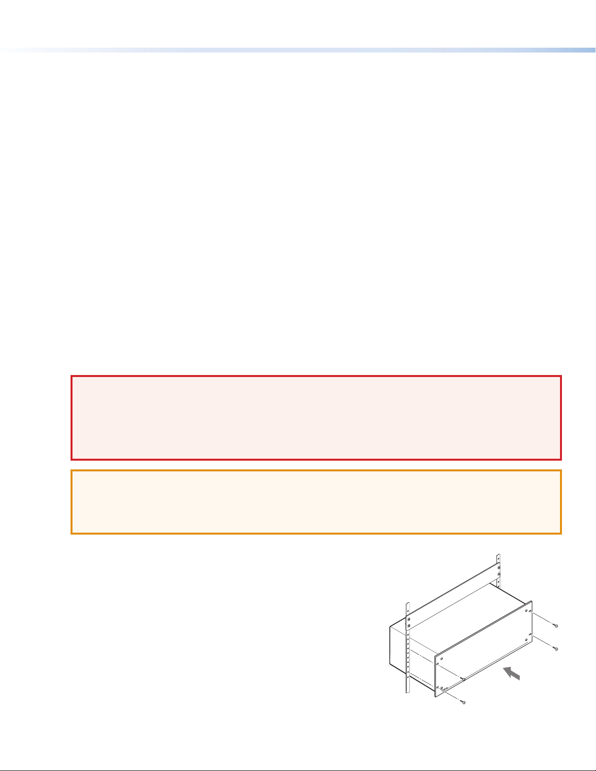
1. Disconnect power from all equipment.
2. (Optional) Mount the unit to a rack using the supplied screws (see the
illustration at right).
3. Connect the video inputs and outputs. Connect HDMI sources to
connectors on the installed input cards and HDMI displays or DTP receivers
to connectors on the output cards. Secure each HDMI device cable to the
connector with a provided LockIt® HDMI Cable Lacing Bracket.
4. Connect a control device — For remote control, connect a control device or
a computer to:
a. The RJ-45 LAN A or LAN B jack to enable conguration and control of the
Quantum Ultra via SIS commands or VCS
b. (Optional) The USB mini B Cong connector to enable conguration and
control via SIS commands or VCS
c. (Optional) The 3-pole captive screw RS-232 connector to enable serial control via SIS commands
5. Connect power to the Quantum Ultra primary and redundant (optional) IEC connectors.
2
Page 3
Product Category
6. Power on the Quantum Ultra and all connected devices.
7. Download and install the Videowall Configuration Software on your computer.
8. Configure sources, displays, and presets for your videowall system using VCS (see “Conguring the Videowall”).
Configuring the Videowall
The Videowall Conguration Software program enables you to congure and control the Quantum Ultra from the computer by
creating a videowall project. This section provides the procedure for setting up the videowall using the software. For detailed
information, see the Videowall Configuration Software help le, accessible from the software.
Downloading, Installing, and Starting the Software
1. Download the Videowall Conguration Software from
www.extron.com.
a. On the Extron web page, hover the mouse pointer over the
Download tab (see 1 in the illustration at right).
b. Slide the pointer to the Software link (
column and click the link.
c. On the Download Center page, click the V link in either of
the alphabet links at the top and bottom of the screen.
d. Scroll to locate VCS on the list, and click its Download link at
the far right.
e. On the next screen, enter the requested information and click the Log in button. If you need an Extron Insider ID,
contact your Extron representative.
f. Follow the instructions on the subsequent screens to download and install VCS. By default, the program les are placed
at C:\Program Files (x86)\Extron\Extron VCS.
2. Open the software program either by double-clicking the VCS icon that is placed on your desktop during
installation (shown at right), or by clicking Start > All Programs > Extron Electronics > Videowall
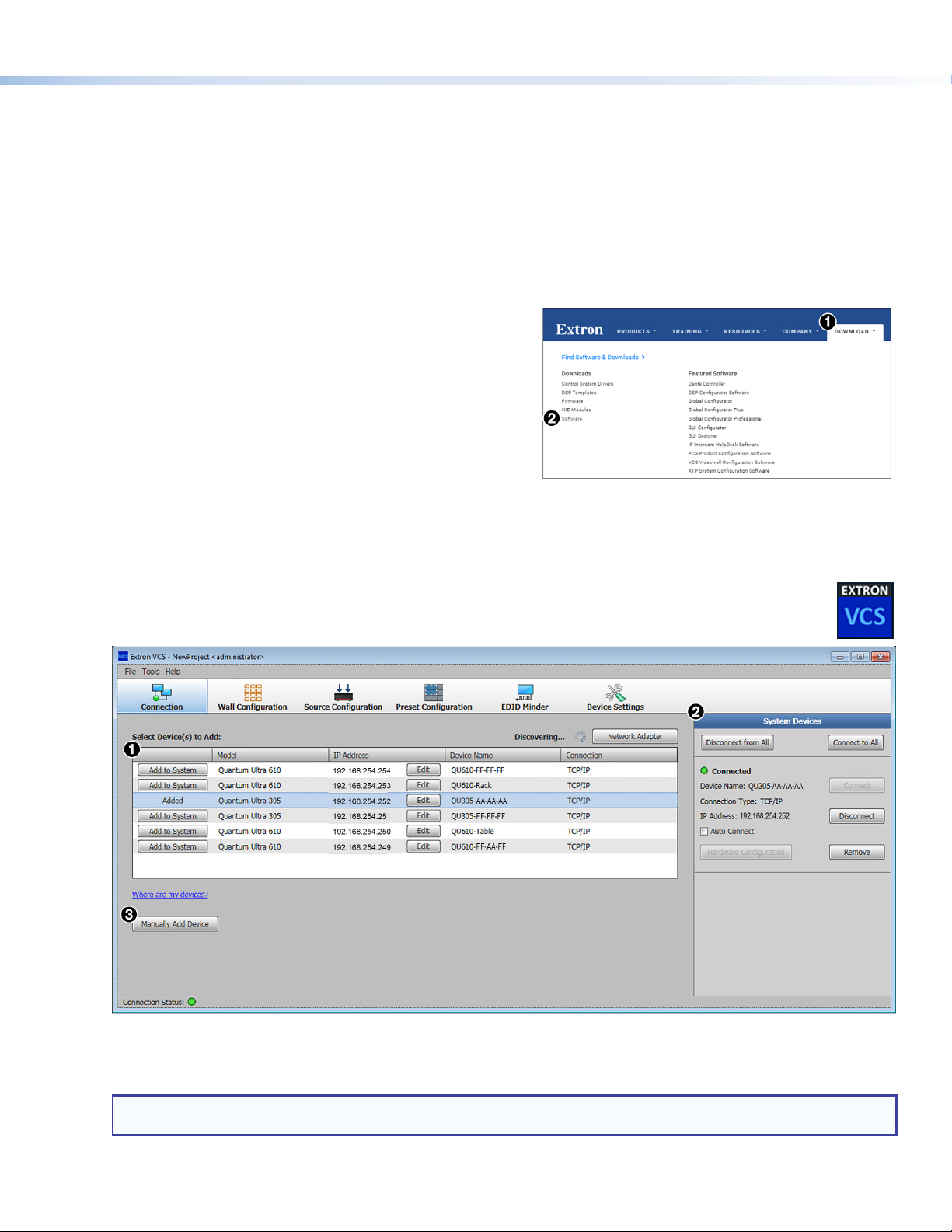
Conguration Software. The Extron VCS program opens with the Connection screen (see gure 2).
) in the Downloads
2
Figure 2. VCS New Project Screen
When VCS is rst opened, it searches for devices that are connected to the network. The Select Device(s) to Add:
panel displays a list of Quantum Ultra devices that were detected (see gure 2, 1).
NOTE: A gateway IP address is required on the PC running VCS for the Quantum Ultra to be detected. The gateway
address need not be valid or on the same subnet for the device to be detected.
3
Page 4

Quantum Ultra • Setup Guide (Continued)
Locate your Quantum Ultra on this list and click the Add to System button at the left of the device name. Connection
information is displayed in the System Devices panel. If the computer is successfully connected to the device, the word
Connected is displayed, preceded by a green dot, in the System Devices panel (see figure 2, 2, on the previous page).
If you do not see your device in the Select Device(s) to Add panel:
a. Click the Manually Add Device button (
Device window opens (shown at right).
b. In the IP Address eld, enter the address of the Quantum to be
connected and select the Pull from Hardware radio button.
c. Click Add. The connection information for the device is displayed
in the System Devices panel (3). A unit added by this method is
not displayed in the Select Device(s) to Add panel.
3. Edit IP address settings for your device as needed.
a. In the Select Device(s) to Add panel, click the Edit button (see
b. The Communication Settings dialog box opens. In this window, you can enter a new IP address and edit other IP
settings as desired.
To enable Dynamic Host Conguration Protocol (DHCP), select the DHCP checkbox. When this box is selected, an
available IP address is assigned automatically to the Quantum when it is connected to a supporting network. (When this
box is selected, all other IP settings elds become read-only.)
If you added this device manually, click the Device Settings button (shown at right) on the taskbar.
On the Device Details screen, click the Communication Settings button to display the
Communication Settings window.
If the device cannot be detected or manually added, connect to the Quantum Ultra using USB or RS-232 and congure the
IP address using SIS commands.
). The Manually Add
3
in the illustration below).
1
Setting Up the Videowall Using VCS
To use the VCS program to congure the videowall, start by setting up a project. In the project, you dene the Quantum Ultra
processors, create one or more videowalls, set up video sources and outputs, and create presets. At the top of the Quantum Ultra
screen is a row of task buttons. After you have connected to the Quantum Ultra device (processor or chassis) or devices you will
be using, click the buttons to access screens for the setup tasks. For best results, perform the following setup procedures in the
order they are presented in this guide.
Figure 3. Wall Configuration Screen
4
Page 5

Product Category
Wall Configuration
Click the Wall Conguration button (shown at right) to congure the outputs and to select the output
channels on the Quantum Ultra device or processors for the videowall.
The Wall Conguration screen appears, providing a Canvas to set up the wall (see figure 3 on the previous page).
1. Name the Canvas. By default, the rst videowall conguration (Canvas) you will dene is named Canvas 1 (see figure 3,
). In the Canvas Name eld, you can customize the name if desired (2). Each Canvas that is created (a maximum of 10) is
1
assigned an incremented number that appears in the Canvas ID eld and is used in SIS commands.
2. Select the number of displays. In the incremental spin boxes labeled Number of Displays (
number of displays that will be in the columns and the rows of the videowall. In the example in gure 3, 4, the wall has ve
columns by three rows.
3. Configure the outputs. The settings on the menus in the output conguration panel apply to all displays in the Canvas:
z Resolution (
z Master Refresh Rate (
NOTE: This rate not only applies to all the displays on the first Canvas, but limits selectable refresh rates on all other
canvases that are added. (See the VCS program help file for information about using multiple canvases.)
) — From this menu, select the output resolution for the displays.
5
) — From this menu, select the refresh rate for the displays.
6
) select or enter the
3
z Output format (
Auto.
z HDCP Mode (
encrypt the output (default), to never encrypt the output, or to attempt to encrypt the output for 1 minute, then revert to
an unencrypted state (not allowing display of HDCP encrypted sources if authentication with the sink device fails).
z HDCP Notication (
contains HDCP-protected content and the outputs cannot be encrypted.
z Display Rotation (
physically rotated: +90° (90 degrees clockwise), -90° (90 degrees counterclockwise) or 0° (no
rotation). The example at right shows a videowall that has three rotated displays.
NOTE: Output rotation is available only on the even numbered channels and disables the
4. Define the Quantum device and output in the output assignment panel (
display on the videowall. Do either of the following:
z Automatic method — (Recommended) Click the Auto Assign Outputs button (
automatically assign a device and an output channel to each display in the videowall.
Output card slot and connector numbers are assigned to the displays in numerical order.
The displays are shown on the Canvas numbered from left to right, starting in the upper-left
corner with Display 1.
z Manual method —
a. Select a Quantum device for a display on the videowall. Click <Undened> beside the
number of the display to be assigned, and select a device from the drop-down menu.
b. Select an output card and slot number for the display. Click <Undened> in the Output
Assignment column, in the row of the display to be assigned. On the output drop-down menu,
all output connectors are listed in order by card slot number and connector number. In the
example at right, 5.1 signies connector 1 on the output card in slot 5 on the device.
Repeat this step for each display on the videowall to which you want to assign a Quantum device
and output connector. (This guide assumes you are conguring a videowall with one device. For
information on conguring a videowall with multiple Quantum processors, see the VCS help le).
5. In the Mullion/Edge Blending Compensation panel (
(for more detailed information, see the VCS help le):
z Mullion Compensation — Displays controls that let you specify the mullion space around the displays in pixels,
inches, centimeters, or millimeters. If not using pixel values, you must also enter the diagonal size of the screen.
z Edge Blending – Displays controls that let you specify the amount in pixels of horizontal and vertical overlap of the
videowall outputs.
6. If desired, from the menu in the Test Pattern panel (
8
odd numbered channels.
) — From this menu, select the output format (AUTO, DVI RGB 444 or HDMI RGB 444). The default is
7
) — From this menu, select how to manage HDCP encryption on the outputs. You can select to always
) — From this menu, select to enable or disable a green screen notication when the input signal
9
) — Select the radio button for the angle at which the displays will be
¢
) select either of the following radio buttons
¥
), select a test pattern to aid in optimizing the wall conguration.
¦
) for each
£
¤
) to
5
Page 6

Quantum Ultra • Setup Guide (Continued)
Source Configuration
Each source that will be used in a project must have a corresponding source denition in VCS. On the
taskbar, click the Source Conguration button (shown at right ) to display the Source Conguration
screen and congure the inputs. The Quantum Ultra detects the number of HDMI connectors in the
Quantum Ultra chassis and displays them in the Source Conguration Tree (left panel of the source workspace, see gure 4,
). By default, sources are named according to the slot number followed by the input connector number, (for example, HDMI 1.2
2
indicates that the HDMI source is attached to HDMI input connector 2 on the card in slot 1).
To refresh the picture source list, or if the pictures are not detected, click Picture in the Source Conguration
Tree, then click the Detect button (shown at right), located above the source tree.
Figure 4. Source Configuration Window
1. Configure the HDMI inputs. In the Source Conguration Tree, click the source name to be congured. If necessary,
click the + sign to the left of HDMI in the source tree to expand the HDMI source list. The HDMI Source Conguration
panel opens in the center panel of the Source Conguration screen, with the name of the source entered in the Input
Name eld. The following items can be congured or selected for an input (see gure 4):
Input Name — If desired, edit the name for this source.
3
HDCP Authorization — From this menu, select whether or not the Quantum input will report to a source as an HDCP
4
authorized device, thereby allowing HDCP-encrypted content. The default is Enabled.
Aspect ratio — From this menu, select whether input signals will fill the entire window (Fill Window), or be
5
compensated to maintain the native aspect ratio of the input signal (Follow Input). The default is Fill Window.
Overscan — From this menu, select a default overscan mode to apply to SMPTE input rates. This zooms and crops
6
SMPTE inputs to mask edge artifacts and ancillary data that may be visible in broadcast signals. The default is 0%.
Resolution Support — From this menu, select the maximum input resolution that can be supported by the input. The
7
options are Up to 165MHz or Up to 300MHz. To support 300 MHz, the combined processing power of inputs 1 and 2, or
3 and 4 is required. If Up to 300MHz is selected, input 1 is disabled in favor of input 2, and input 3 is disabled in favor of
input 4.
Input Grouping — From this menu, select whether the input will be grouped with other inputs as part of a two-column,
8
quad, or extended desktop display (see the VCS help file for details).
Source Rotation — Select the radio button for the angle at which the source signal will be rotated when displayed on
9
the output: +90° (90 degrees clockwise), -90° (90 degrees counterclockwise) or 0° (no rotation). The default is 0°.
Refresh button — If a signal is present, the Input Status panel displays the input resolution, refresh rate, and HDCP
¢
status. Click this button to update the input signal status.
Disable Source checkbox — Select this checkbox if the source does not need to be displayed on the videowall.
£
6
Page 7

Product Category
2. (Optional) Add pictures, clocks, VNC, and text sources. You can display a picture, a clock, a VNC stream, and a text
string on the videowall. To congure any of these sources:
a. In the Source Conguration Tree, click the item to be added (Picture, Clock, VNC, or Text).
b. Above the Source Conguration Tree, click the Add button or right-click the source type to add and select Add.
z For a picture, Picture n is added below Picture. Click Picture n to open a dialog
box that lets you locate and upload an image from the computer to the Quantum (only
.bmp, .jpg, .png, and .tif formats are supported). If picture les are already on the
Quantum but do not appear in this panel, click Detect to display them. Click the name
of any listed picture to congure how the image will be displayed.
z For a clock, Clock n is added below Clock in the source tree. To congure the clock, click
on its name in the source tree. You can set such parameters as the clock name, the time and
date display format, and the time zone.
z For a VNC stream, VNC n is added below VNC in the source tree. To set up and congure a
connection with a VNC server, click on its name in the source tree.
z For text, Text n is added below Text in the source tree. To add and congure text in a
window, click on the text window name in the source tree. You can set such text parameters
as font, position, and background color.
EDID Assignment
Assign EDID to any of the inputs as desired. Extron factory-loaded default EDID, EDID from the displays
connected to the Quantum output ports, and HDMI or DVI EDID that have been imported or saved into
the VCS EDID library can be assigned to the HDMI inputs. To assign EDID, click EDID Minder (shown at
right) on the taskbar to display the EDID Minder screen. For details about this screen, see the VCS help le.
Window Preset Configuration
A window preset, or scene, is a set of one or more windows in which video sources are displayed on a videowall. Window layout
parameters, including size, position, and content, are stored in the presets. Presets can be recalled and
displayed using VCS or SIS commands (see the Recall window preset command on the next page).
1. On the taskbar, click the Preset Conguration task button to display the preset conguration
workspace (see gure 5, 1). The Canvas in this workspace is a virtual representation of the videowall
you set up on the Wall Conguration screen (see Configuring the Videowall on page 3).
Figure 5. Preset Configuration Window
2. Specify the sources to be displayed on the videowall by adding source windows:
a. Click on a source name (HDMI input, picture, clock, VNC, or text) in the Sources (left) panel
(2) and drag it to the desired location on the Canvas. A window containing the source
name appears on the Canvas (see the illustration at right). You can also drag in a Window
without Source, for which no input signal is displayed in the window on the Canvas.
7
Page 8

b. Congure the source window:
z Resize it by clicking on it and dragging the resizing handles at the sides and corners.
z Reposition it by dragging and dropping it at the desired location on the Canvas.
z Double-click on it to ll the display or displays on which it was placed.
z Change the source in the window by right-clicking and dragging a different source onto the source
window. Drop the new source when the target window turns red (shown at right).
z Right-click on it and select Window Conguration from the menu to open the Window conguration dialog
box. In this box you can specify parameters for the window border, text on the border, and overlay text.
c. Repeat steps a and b for each additional source to be added.
3. If a window completely or partially covers another window, set the priority for each window by
selecting the window, then clicking a priority icon on the toolbar above the Canvas (see figure 5,
, on the previous page). The priority number of the window (P1, P2, and so on) is displayed in the
3
lower-left corner of the window on the Canvas (see the illustration in step 2a on the previous page). You can also use this
toolbar to align multiple windows with each other and to set the size of multiple windows on the Canvas.
4. When nished, save the window layout as a preset as follows:
a. In the Presets list in the lower-left corner of the screen (see figure 5,
), select a slot to which the preset will be
4
saved. (If the slot does not have a preset assigned to it, it is labeled with <Undened>.)
b. Click Save. The preset slot becomes a text eld with the label Window Preset nnn (where
nnn is the 3-digit preset number that indicates the preset slot number).
c. Enter a name for the preset (32 characters maximum) or click outside the text eld to keep the current name.
SIS Commands
The Quantum Ultra can be controlled with SIS commands via USB, RS-232, or LAN connection (Telnet port 23). This table lists
some basic commands. For a full list of SIS commands and variables see the Quantum Ultra User Guide, at www.extron.com.
Command
Input Selection
Select input
View current input
Window Presets
Recall window preset
Window Border Style
Set window border style
View window border style
IP Configuration (These commands apply only to the LAN A port).
Set DHCP on and off
View DHCP setting
Set IP address
View IP address
Commit and reboot
ASCII Command
(Host to Scaler)
X#
* X% * X! ! Grp X# • Win
X#
* X% !
X2%
1* X# *
E
B X# * X% *
E
B X# * X% WNDW
E X1)
E
DH
E X11$
E
CI
E
1BOOT
. 1Rpr X# *
X7%
WNDW
} X7%]
}
DH
} X1)]
}
CI
} X11$]
}
Response
(Scaler to Host)
X!]
}
Wndw B X# * X% *
Idh
Ipi •
Boot1
X1)]
X11$]
]
X% • In X!]
X2%]
X7%]
Additional Description
Select input X! for window X% on Canvas X#.
View current input X! in window X% on Canvas X#.
Recall window preset
Set the border style of window X%, on Canvas X#,
X7%
to
.
View current border setting
Canvas X#.
Enable or disable DHCP.
View DHCP setting
Set the IP address for the unit to
View IP address
Commit IP changes and reboot Quantum Ultra.
X2%
on Canvas X#.
X1)
. Default is 0 (off).
X11$
.
X7%
for window X% on
X11$
.
KEY:
X!
= Input (assigned by VCS): 0001 – 9999. Response is four digits with leading zeros.
0001 – 0999 = physical video connections on all Quantum chassis in the system.
1000 – 9999 = network and local PC sources dened in the system.
X#
= Canvas: 01 – 10. Response is two digits with a leading zero.
X%
= Window: 001 – 999. Response is three digits with leading zeros.
X1)
= On or off: 0 = off (disabled), 1 = on (enabled).
X2%
= Window preset: 001 – 128. Response is three digits with leading zeros.
X7%
= Window border style preset: 000 – 127. 000 = no border. Response is three digits with leading zeros.
X11$
= IP address in the format nnn.nnn.nnn.nnn. Default is 192.168.254.254.
© 2017-2018 Extron Electronics — All rights reserved. All trademarks mentioned are the property of their respective owners. www.extron.com
8
68-2760-50
Rev. C 07 18
 Loading...