

Page 1

IMPORTANT:
IMPORTANT:
Go to www.extron.com for the
complete user guide, installation
NetPA Ultra Series • Setup Guide
instructions, and specifications.
The NetPA Ultra Series is a series of DSP and Dante®-enabled audio power amplifiers for use in a low-impedance speaker systems or
high-impedance line distribution audio systems.
NetPA U 1002 models deliver two channels of 100 watts, and is available in the following configurations:
• NetPA U 1002 (8 Ω/4 Ω) • NetPA U 1002-70V (70 V) • NetPA U 1002-100V (100 V)
NetPA U 1004 models deliver four channels of 100 watts, and is available in the following configurations:
• NetPA U 1004 (8 Ω/4 Ω) • NetPA U 1004-70V (70 V) • NetPA U 1004-100V (100 V)
The NetPA Ultra Series amplifiers all feature a compact 1U, 1/2-rack enclosure. The amplifiers have mounting holes for 9” and deeper
rack shelves, and are plenum rated with an optional flex conduit adaptor. The units are convection cooled.
This guide provides instructions for an experienced installer to set up and operate these power amplifiers. The setup guide features the
NetPA U 1004, but the other amplifiers are installed in the same manner. For full installation, configuration, and operation details, see
the NetPA U 1004 Series User Guide available at www.extron.com.
Installation Steps
Step 1 — Mounting onto a Rack
Turn off all of the equipment and disconnect it from the power source. Mount the amplifier as required. They can be securely mounted
in a variety of locations, using optional Extron Mounting Brackets and accessories (see the Extron website for compatible optional
mounting accessories) or using the included 3-piece bracket system. The brackets do not come attached to the amplifier.
The following sections describe two methods of rack mounting the amplifiers.
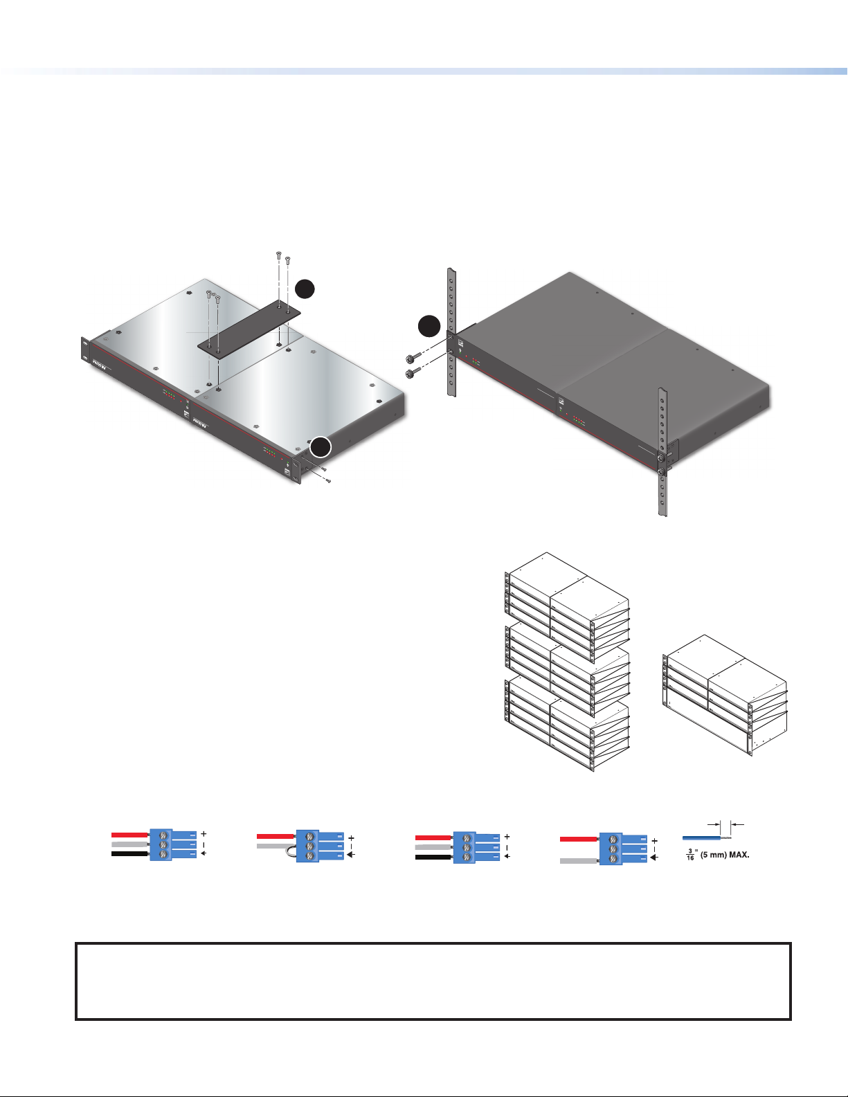
Rack Ear Mounting (Single Unit)
All of the amplifiers ship with a set of rack ears, so these half rack-width amplifiers can be installed in a full rack-width space. Mount the
amplifier with rack ears as follows:
1. If the amplifier has its rubber feet installed, remove them.
2. Attach the rack brackets (one long and one short) to the sides with the four provided #6 machine screws (
3. Insert the amplifier into the rack and align the holes in the rack ears with the holes on the rack.
4. Secure the amplifier to the rack using the four provided 10-32 x 3/4” screws (
1
OV
E
R
NetP
TEMP
e
1
2 3
P
O
W
E
R
AMP
L
IF
IE
R
4
LIMITER/PROTECT
S
SIGNAL
NetP
POWER A
MPL
IFIER
S
N
e
t
P
A U 1
00
4 S
B
P
O
WE
R
AMP
L
IF
IE
R
NetP
S
2
).
2
O
VE
R
T
E
M
P
e
1 2 3
4
L
I
M
IT
ER/
SI
P
R
G
OT
N
A
E
L
C
T
NetP
P
O
W
E
R
A
M
P
L
IFIE
R
S
NetPA U 1004 SERIES
1
).
Figure 1. NetPA U 1004 Rack Ear Mounting
1
Page 2
e
e
ES
RS
S
S
NetPA Ultra Series • Setup Guide (Continued)
The NetPA Ultra Series amplifiers all ship with a bridge plate connector to connect two amplifiers together and form full rack-width unit.
Mount and connect two amplifiers as follows:
1. If the amplifier has its rubber feet installed, remove them.
2. Position two amplifiers upside down and next to each other as shown below.
3. Use the bridge plate connector and the four provided #4 machine screws to connect the two units together (
4. Attach the two short rack ears to the units with the four provided #6 machine screws (
2
).
5. Insert the amplifier into the rack and align the holes in the rack ears with the holes on the rack.
6. Secure the amplifier to the rack using the four provided 10-32 x 3/4” screws (
Mounting
screws (4)
3
).
1
3
OVER
NetPA U 1004 SERIES
LIFIERS
POWER AMP
Net
SIGNAL
LIMITER/PROTECT
1 2 3 4
e
TEMP
OVER
NetPA U 1004 SERIES
R AMPLIFIERS
E
POW
Net
SIGNAL
LIMITER/PROTECT
4
1 2 3
2
e
TEMP
OVER
TEMP
e
1
2
LIMITER/PROTECT
SIGNAL
NetPA U
POWER AMPLIFIERS
LTRA
NetPA U 1002 SERIES
OVER
TE
M
P
e
1 2 3 4
LIMITER/PROTECT
SIGNAL
NetPA U
P
LTRA
O
WER A
M
PLIF
IERS
NetPA U 1004 SERIES
1
).
Figure 2. NetPA U 1004 Bridge Plate Rack Mounting
Ventilation Recommendation
Excessive heat decreases the optimal lifetime of the power amplifier.
An Over Temp LED indicator on the front panel of the amplifier
lights red when the recommended operating temperature has been
exceeded.
The NetPA Ultra amplifiers need to be arranged in a rack environment,
so that the environment around the amplifier around does not reach
or exceed +122 °F (+50 °C). No more than four amplifiers should
be stacked one-on-top-of-the-other without an open rack space in
between as seen in the image to the right.
The NetPA Ultra amplifiers can also be arranged above or below a
non-NetPA Ultra device.
Step 2 — Captive Screw Audio Cable Wiring
Wire the captive screw connectors to the input or output as shown in the following figures.
Tip
Ring
leeve
Balanced Input
Figure 3. Input Wiring
Tip
Sleeve
Jumper
Unbalanced Input
Tip
Ring
leeve
Balanced Output
Figure 4 Output Wiring
Vent Space
Vent Space
Vent Space
Vent Space
Vent Space
Tip
Sleeve
Unbalanced Output
Vent Space
Vent Space
Do not tin
the wires!
NOTE:
• Balanced or unbalanced stereo sources can be connected with 6-pole connectors.
• When using the 5-pole CSR 6 captive screw to RCA adapter, connect it so the far left plug is inserted into the far left jack of the
6-pole input.
2
Page 3
ATTENTION:
• For unbalanced audio outputs, connect the sleeves to the ground contact. DO NOT connect the sleeves to the negative
(-) contacts.
• Pour l’audio asymétrique, connectez les manchons au contact au sol. Ne PAS connecter les manchons aux contacts
négatifs (–).
Step 3 — Remote Ports
Rx
Tx
Do not tin
the wires!
STANDBY
Figure 5 Remote Volume Control and Standby Ports
• Standby mode is forced when the Standby pin is connected to the second G pin. The power LED on the front panel lights
amber when the amplifier is in Standby mode indicating that the amplifier is still receiving power despite the fact that it has
turned off all the outputs.
NOTE: The enabling and disabling of the auto-standby timer is handled through SIS or DSP Configurator. For more
details, consult the NetPA Ultra Series User Guide.
• Connect a 3.5 mm 3-pole captive screw connector to remotely control the volume via SIS commands, and connect a 3.5 mm,
2-pole captive screw to place the amplifier into Standby mode.
Protocol for the RS-232 port:
• 38,400 baud • 1 stop bit • 8 data bits • no parity
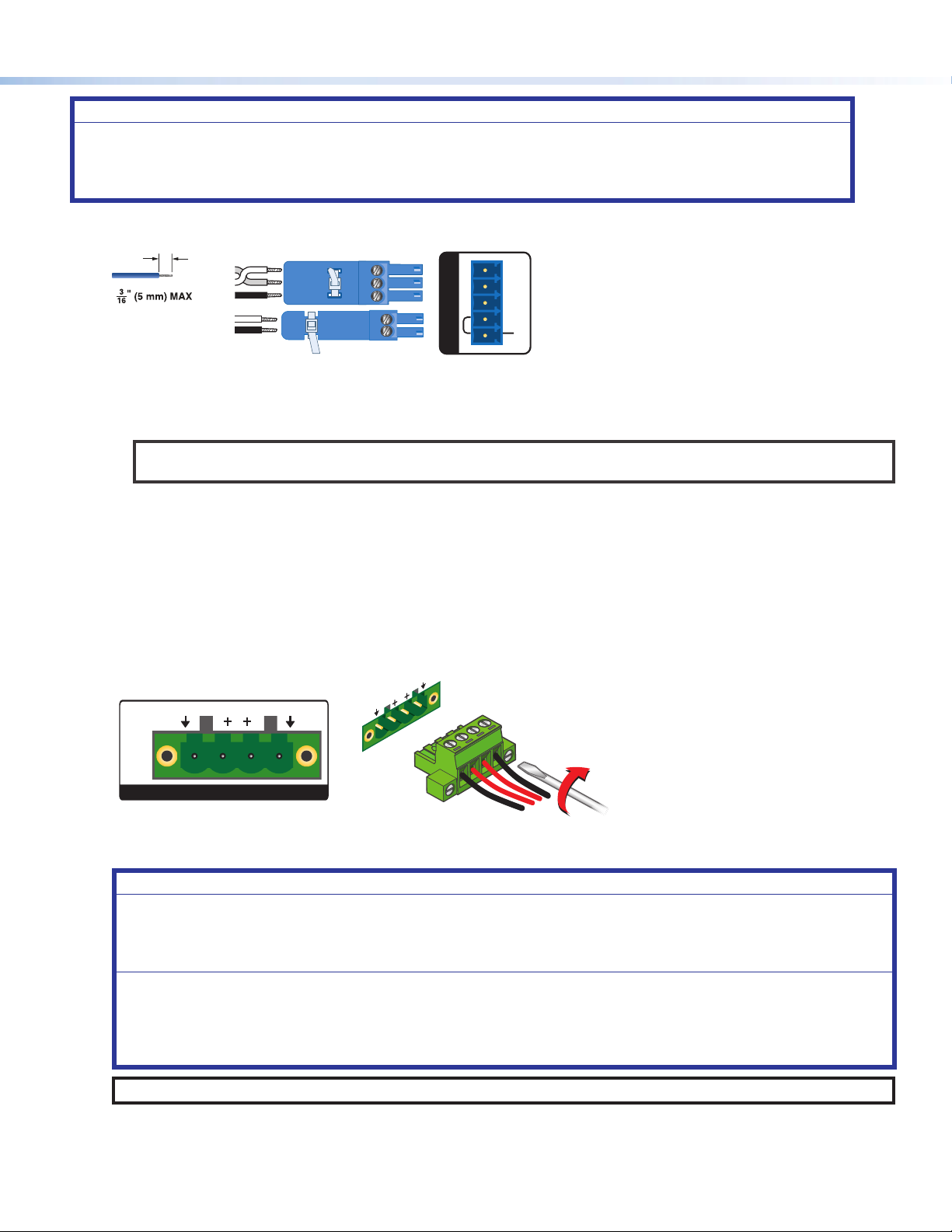
Step 4 — Speaker Wiring
Connect a four 4-pin, 5 mm captive screw connector for two channels of speaker output on the NetPA U 1002 group of amplifiers
and up to four channels on the NetPA U 1004 group of amplifiers. Each port has a screw flange to secure the plug to the
connector. Figure 6 shows how to wire the captive screw connector.
RS-232
Tx Rx
G
STANDBY
G
REMOTE
G
G
2
+B R—
1
21
CLASS 2
WIRING
100V OUTPUTS
Figure 6 Speaker Output Port and Wiring Diagram
ATTENTION:
• Do not tie channel output pins to each other or to ground. Doing so will short out the outputs, damage the amplifier, or
both.
• Ne pas lier les sorties 1 et 2 des canaux entre elles ou à la terre. Les sorties pourraient être court-circuitées et/ou
l’amplificateur pourrait être endommagé.
• To avoid risk of damage to the amplifier or the speakers, always connect low-impedance speaker loads (8 Ω/4 Ω) and
high-impedance speaker loads (70 V) to the appropriately marked output connectors on the amplifier.
• Pour éviter tout risque de détérioration de l’amplificateur ou des enceintes, connectez toujours les charges de l’enceinte
faible impédance (8 Ω/4 Ω) et les charges de l’enceinte haute impédance (70 V) aux connecteurs de sortie correctement
identifiés sur l’amplificateur.
NOTE: You must use Class 2 wiring for this output to comply with UL requirements.
3
Page 4

12345678
RJ-45
Connector
Insert Twisted
Pair Wires
Pins:
A cable that is wired as TIA/EIA T568A at one
end and T568B at the other (Tx and Rx pairs
reversed) is a "crossover" cable.
T568B T568A
Crossover Cable
(for direct connection to a PC)
End 1 End 2
Pin Wire Color Pin Wire Color
1 white-orange 1 white-green
2 orange 2 green
3 white-green 3 white-orange
4 blue 4 blue
5 white-blue 5 white-blue
6 green 6 orange
7 white-brown 7 white-brown
8 brown 8 brown
NetPA Ultra Series • Setup Guide (Continued)
Step 5 — AT Port
Connect a RJ-45 connector to the AT port to connect and
communicate with the Dante network. It is also one of the interfaces
DSP Configurator uses to communicate with the amplifier. The Link
LED indicates when a connection is made.
Go to Configure Dante Device Settings on page 5 for information
on Dante settings. See the image to the right for wiring.
Step 6 — Powering on Amplifier and Adjustments.
Reconnect all the power cables and switch on the rest of the
equipment before powering on the power amplifier. The amplifier will boot-up for up to 10 seconds as the front panel LED lights
amber.
Once the boot-up sequence is complete, the amplifier takes more time to sync with the Dante network, and begin the playback of
streamed content. Once playback begins, the front panel LED lights green.
ATTENTION:
• The amplifier must be powered on last.
• L’amplificateur doit être mis sous tension en dernier.
4
Step 7 — Checking LEDs
Check the Limiter/Protect and Signal LEDs on the front and rear panels to see if any problems are encountered (see “Front Panel
Features and Troubleshooting” in the NetPA Ultra Series User Guide for more information).
Step 8 — DSP Configurator Software Installation
There are no hardware controls for any of the units in the NetPA Ultra Series. Configuration and control is done using either Extron
DSP Configurator software or SIS commands. To learn about full computer requirements, see the DSP Configurator product
page on www.extron.com.
Download DSP Configurator from the Extron Website
1. From the Extron home page (www.extron.com), click the Download tab to open the Download page.
2. Under Software (located on the left side of the page), select DSP Congurator Software. The DSP Configurator Software
product page opens.
3. Click the Download button and follow the on-screen instructions.
NOTE: An Extron Insider account is required to download DSP Configurator.
Step 9 — NetPA Ultra Series Configuration
When power is connected to any unit of the NetPA Ultra Series and the rest of the audio system, audio output can be easily
configured to any listening environment via the DSP Configurator. The following steps details how to configure a NetPA Ultra Series
amplifier and uses the NetPA U 1004 as an example. However, all of the amplifiers are configured in the same way.
Downloading and Installing Dante Controller
1. From www.extron.com, hover over the Download tab at the top of the page.
2. From the Featured Software list, select Dante Controller. The Dante Controller product page opens.
3. Click the blue Download button.
4. Select Run to run the Dante Controller installer. Select Save to save the install file to run at a later time.
5. If you choose to run the file, follow all prompts. If you saved the file, click the saved file to begin installation when
ready.
NOTE: The installed Dante Controller program files are saved in:
C:\Program Files (x86)\Audinate\Dante Controller\DanteController.exe.
Page 5

Configure a NetPA Ultra Series Amplifier
1. Ensure the control computer is connected to either the AT port, RS-232 port or the rear panel USB configuration port.
2. Start the DSP Configurator software. From the splash screen drop-down menu, select the NetPA Ultra Series unit corresponding
to the unit connected to the control computer. Click OK. The main workspace opens.
3. The software starts in Emulate mode:
a. To create a configuration file offline and then upload that configuration to a NetPA Ultra Series unit at a later time, remain in
Emulate mode and save the configuration file.
b. To upload a configuration to the NetPA Ultra Series unit or download the current configuration from a unit, enter Live mode.
When in Live mode, changes made in DSP Configurator immediately affect the connected NetPA Ultra Series unit. To enter
Live mode, click Live at the top of the DSP Configurator workspace, or select Tools > Connect to Device, or press
<F6> on the keyboard.
NOTE: When Live mode is selected, a connection dialog box appears. Select the desired connection type and follow the
on-screen prompts (see the NetPA Ultra Series User Guide for more information on connecting live to a device).
The main workspace provides access to mix matrices, gain blocks, and
DSP processors for configuring a NetPA Ultra Series unit. It also provides
a menu bar across the top with additional configuration tools. For more
information on using the DSP Configurator, see the “DSP Configurator”
section of the NetPA Ultra Series User Guide, or the DSP Configurator
Help File that can be accessed by selecting Help > Contents or
pressing <F1>. Most dialog boxes within DSP Configurator contain a
Help button ( ) in the top right corner. Click this button to open the
help file topic for that particular dialog box.
Configure Dante Device Settings
Dante settings in the NetPA Ultra Series can be configured from DSP
Configurator. The device can be named in the Dante Device Settings,
which assists with indentifying a specific device in the Dante Controller software when there are multiple entries on the audio network.
ATTENTION: It is crucial that a Dante device be named before audio subscriptions with other devices are established. Existing
subscriptions are removed when a unit is renamed.
To configure Dante device settings:
1. Open DSP Configurator and connect live to the NetPA Ultra Series.
2. Select Tools > Device Settings. The Device Settings dialog box opens.
3. From the tabs at the top of the Device Settings dialog box, select Dante Device.
4. In the Device Name field, give the NetPA Ultra Series unit a name (recommended to be device model and location) so that it can
be easily identified in Dante Controller. No spaces are allowed in the name.
5. Dante device network settings can also be configured in this dialog box. Use the radio buttons and text fields to choose DHCP
(recommended) or Static IP and enter a static IP address configuration.
6. Click Apply.
7. Click OK to confirm changes and close the Device Settings dialog box.
Renaming the NetPA Ultra Series Amplifier in Dante Controller
1. From the control computer Start menu select: All Programs > Audinate > Dante Controller > Dante Controller
2. The Dante Controller - Network View screen opens. All Dante devices on the network are discovered and listed.
3. From the Device menu, select Device View or press <Ctrl+D> on the keyboard.
4. The Dante Controller - Device View dialog opens. Select the device being configured from the (Select a Dante
Device...) drop-down list. The Device View dialog populates with the selected NetPA Ultra Series information.
5
Page 6

NetPA Ultra Series • Setup Guide (Continued)
Figure 7 Populated Device View Dialog Box
5. Click the Device Config tab to open the Device Config page.
6. In the Rename Device panel, enter the new name of the device in the text field.
NOTE: No spaces are allowed in the name and names should be significant identifiers. For example,
NetPAUAmplifier-MainRack
7. Click Apply. A confirmation prompt opens. Click Yes to confirm the new name.
8. Repeat as necessary for all devices.
Creating a Physical Dante Network
A physical network is required to share Dante audio channels among Dante-enabled devices like those found in the NetPA Ultra
Series. Other devices capable of sending and receiving audio over a Dante network must be on the same physical network in order to
communicate with Dante. (see figure 8 for an example of a Dante network.)
Wirele ss Mic 1
Wirele ss Mic 2
Extron
SF 26CT
Two-Way Ceiling Speakers
Extron
SF 26CT
Two-Way Ceiling Speakers
selectmut
e
mut
select
e
Ceiling
Ethernet
Ethernet
Ethernet
CONFIG
Extron
XMP 24 0 C AT
Expansion Matrix Processor
ACTIVITY
CLIP
EXP LAN
SIGNAL
Array M ic
INPUTS
1 2 3 4 5 6 7 8 9 10 11 1213 1415 1617 1819 2021 22 2324
XMP 240 C AT
EXPANSION MATRIX PROCESSOR
Extron
OVER
TEMP
21
LIMITER/PROTECT
SIGNAL
Local Audio
Extron
WPD 101 3. 5 mm
AUDIO
Audio Pass-Through Wallplate
- Decorator-Style
Extron
NetPA U 1002 SERIES
Audio Lin e OutAudio Inputs
NetPA U 1002-70V
Power Amplier
Assistive Listening
System Transmitter
Figure 8 Physical Dante Network Diagram
6
Page 7

Dante Network Setup
Use a standard Ethernet cable to connect a NetPA Ultra Series amplifier to a Dante network via the AT port. Launch the Dante
Controller program.
Dante Controller automatically discovers all Dante devices on the network and allows other Dante-enabled devices to communicate
with it. The default device name is the model name followed by the last six characters of the device MAC address (for example,
NetPA-U-xxxxxx). Multiple devices on the same network can present difficulty in identifying inputs and outputs. To avoid confusion,
rename each device to a unique identifier.
NOTE: To simplify setup, connect only one Dante device to the network at a time.
Finding a Dante Device IP Address
1. Open Dante Controller.
2. On the Dante Controller-Network View screen, click the Device Info tab.
3. On the Device Info page, locate the name of the NetPA Ultra Series in the Device Name column. The IP address is
located in the Primary Address column. In the example below, the IP address for the connected NetPA Ultra Series is
192.168.254.254.
Dante Controller Operation
Dante Transmitters and Receivers
A Dante network is comprised of transmitters that output digital audio onto the Dante network and receivers that receive digital
audio input from the Dante network.
• Transmitters output digital audio from the device onto the audio network.
• Receivers take in digital audio from the audio network into the device.
NetPA Ultra Series Transmitters and Receivers
In the NetPA U 1004, the line output signals are parallel to their respective Dante output signal. The signal being sent out of a line
output is the same signal being sent out of its respective Dante output. In the NetPA U 1002, the line outputs are independent of
Dante outputs.
The NetPA Ultra Series AT input channels are Dante receivers because they receive digital audio signal from the Dante network
that can then be routed and mixed into a mix matrix. The NetPA U 1004 has four Dante inputs, while the NetPA U 1002 has two
Dante inputs.
Figure 9 Device Info Page
7
Page 8

Network View Layout
In the Dante Controller software, Dante transmitters are listed
horizontally across the top of the Network View (1), while
Dante receivers are listed vertically on the left side of the window
(2). Creating a link in the connection matrix routes audio from a
transmitter to a receiver (3).
Routing Devices
1. To show the transmitters of a Dante device, click the + box
next to the desired device in the Dante Transmitters
panel, such as NetPA-U-9175f2 (1). The + changes to a
– sign when the details for the device expand.
2. To show the receivers of a Dante device, click the + box next
to the desired device in the Dante Receivers panel, such
as a NetPA-U-MainRack (2).
3. Click the intersection of the desired subscription (discrete
connection) between a transmitter and a receiver (3). A
check mark at the intersection indicates the subscription
is made. A check mark also appears next to the receiver
channel.
NOTE: A receiver can subscribe to only one transmitter.
A transmitter can connect to multiple receivers.
1
2
3
4. To undo routing, click the junction again to disconnect the receiver from the transmitter.
NOTE: After making changes to Dante network routing such as subscriptions, device names, or channel
labels, wait at least 5 seconds before disconnecting or powering down the devices. This ensures that
the new information is properly saved to those devices. Device level configuration such as sample rates,
latency, and clock settings are saved instantly.
For more information on configuring a NetPA Ultra Series unit in Dante Controller, see the “Dante Controller” section of the
NetPA Ultra Series User Guide found on www.extron.com.
For information on safety guidelines, regulatory compliances, EMI/EMF compatibility, accessibility, and related topics,
see the Extron Safety and Regulatory Compliance Guide on the Extron website.
© xxxx-2020 Extron Electronics — All rights reserved. www.extron.com
8
Worldwide Headquarters: Extron USA West, 1025 E. Ball Road, Anaheim, CA 92805, 800.633.9876
All trademarks mentioned are the property of their respective owners.
68-3165-50 Rev. A
07 20
 Loading...