

Page 1

e
N
e
t
PA U
8001 S
UB
OVE
R
TEMP
LIMI
TE
R
/PROT
ECT
SIGNAL
P
OWER A
M
PL
IFIE
RS
111
2
2
2
e
Ne
tPA
U 800
1
SU
B
OVE
R
TE
MP
LIMIT
ER/PRO
TE
CT
SIGNAL
P
OWER
A
M
P
LIFI
ERS
IMPORTANT:
IMPORTANT:
Go to www.extron.com for the
complete user guide, installation
NetPA U 8001 SUB • Setup Guide
instructions, and specifications.
The Extron NetPA U 8001 SUB is an ENERGY STAR-qualied, Dante-enabled subwoofer amplier with onboard audio DSP,
designed specically for use with the Extron SF 10C SUB in-ceiling subwoofer speaker, as well as other 8, 4, or 2 ohm
subwoofers with similar power requirements. The NetPA U 8001 SUB can deliver up to 800 watts at 8 ohms, 650 watts at 4 ohms,
or 325 watts at 2 ohms.
The NetPA U 8001 SUB is 1U high, half-rack width, and rack-mountable. The amplier has mounting holes for 9-inch (22.86 cm)
and deeper rack shelves, and is plenum-rated with an optional ex conduit adapter. The unit is convection-cooled.
This guide provides instructions for an experienced installer to set up and operate the NetPA U 8001 SUB subwoofer amplier.
For full installation, conguration, and operation details, see the NetPA U 8001 SUB User Guide available at www.extron.com.
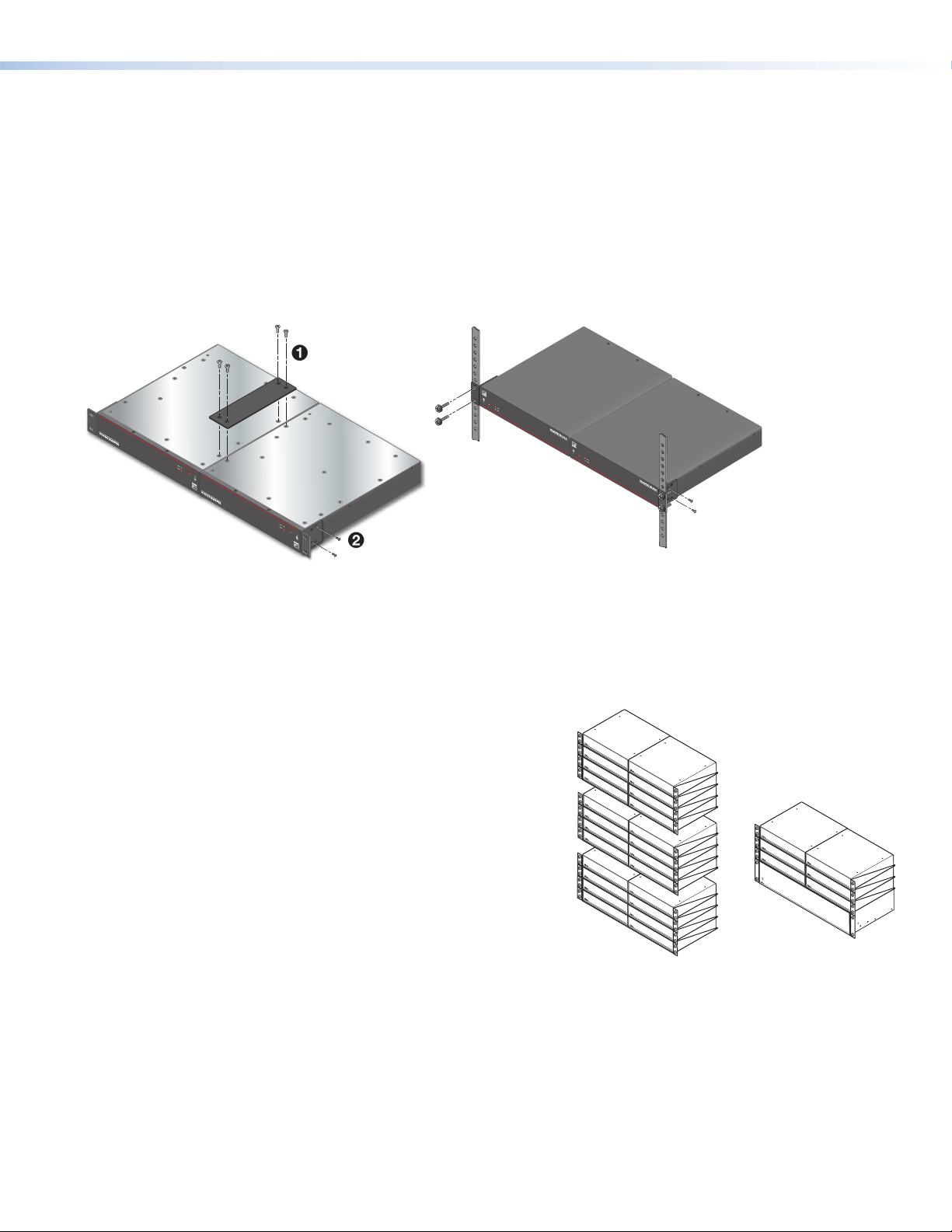
Installation Steps
Step 1 — Mounting onto a Rack
Turn off all of the equipment and disconnect it from the power source. Mount the amplier as required. It can be securely mounted
in a variety of locations, using optional Extron Mounting Brackets and accessories (see the Extron website for compatible
optional mounting accessories), or using the included three-piece bracket system. The brackets do not come attached to the
amplier.
The following sections describe two methods of rack-mounting the ampliers.
Rack Ear Mounting (Single Unit)
The NetPA U 8001 SUB amplier ships with a set of rack ears, so this half-rack width amplier can be installed in a full-rack width
space. Mount the amplier with rack ears as follows:
1. If the amplier has its rubber feet installed, remove them.
2. Attach the rack brackets (one long and one short) to the sides with the four provided #6 machine screws (
1
).
3. Insert the amplier into the rack and align the holes in the rack ears with the holes on the rack.
4. Secure the amplier to the rack using the four provided 10-32 x 3/4-inch screws (
2
).
Figure 1. NetPA U 8001 SUB Rack Ear Mounting
1
Page 2
NetPA U 8001 SUB • Setup Guide (Continued)
Bridge Plate Rack Mounting (Side-by-Side)
The NetPA U 8001 SUB ships with a bridge plate connector to connect two ampliers together and form a full-rack width unit.
Mount and connect two ampliers as follows:
1. If the amplier has its rubber feet installed, remove them.
2. Position two ampliers upside down and side-by-side as shown below.
3. Use the bridge plate connector and the four provided #4 machine screws to connect the two units together (
4. Attach the two short rack ears to the units with the four provided #6 machine screws (
2
).
5. Insert the amplier into the rack and align the holes in the rack ears with the holes on the rack.
6. Secure the amplier to the rack using the four provided 10-32 x 3/4” screws (
Mounting
screws (4)
3
).
OVER
TEMP
e
LIMITER/PROTECT
NetPA U 8 001 SUB
POWER AMPLIFIERS
SIGNAL
LIMITER/PROTECT
e
TEMP
OVER
NetPA U 8 001 SUB
POWER AMPLIFIERS
SIGNAL
LIMITER/PROTECT
e
TEMP
OVER
SIGNAL
POWER AMPLIFIERS
NetPA U 800 1 S UB
OVER
TEMP
e
LIMITER/PROTECT
SIGNAL
POWER AMPLIFIERS
NetPA U 800 1 S UB
1
).
Figure 2. NetPA U 8001 SUB Bridge Plate Rack Mounting
In addition to rack-mounting, the NetPA U 8001 SUB can also be mounted directly to the SF 10C SUB using the mounting
hardware that is included with the speaker. Please see the NetPA U 8001 SUB User Guide for detailed setup instructions.
Ventilation Recommendation
Excessive heat decreases the optimal lifetime of the power amplier. An
Over Temp LED indicator on the front panel of the amplier lights red when
Vent Space
the recommended operating temperature has been exceeded.
NetPA Ultra ampliers need to be arranged in a rack environment, so that
the environment around the amplier does not reach or exceed +122 °F (+50
°C). No more than four ampliers in a group should be stacked without a
Vent Space
ventilation opening between the groups.
The NetPA U 8001 SUB can also be arranged above or below a non-NetPA
Ultra device, but in any case, the environment should never reach or exceed
Vent Space
Vent Space
+122 °F (+50 °C).
Vent Space
Vent Space
Vent Space
2
Page 3
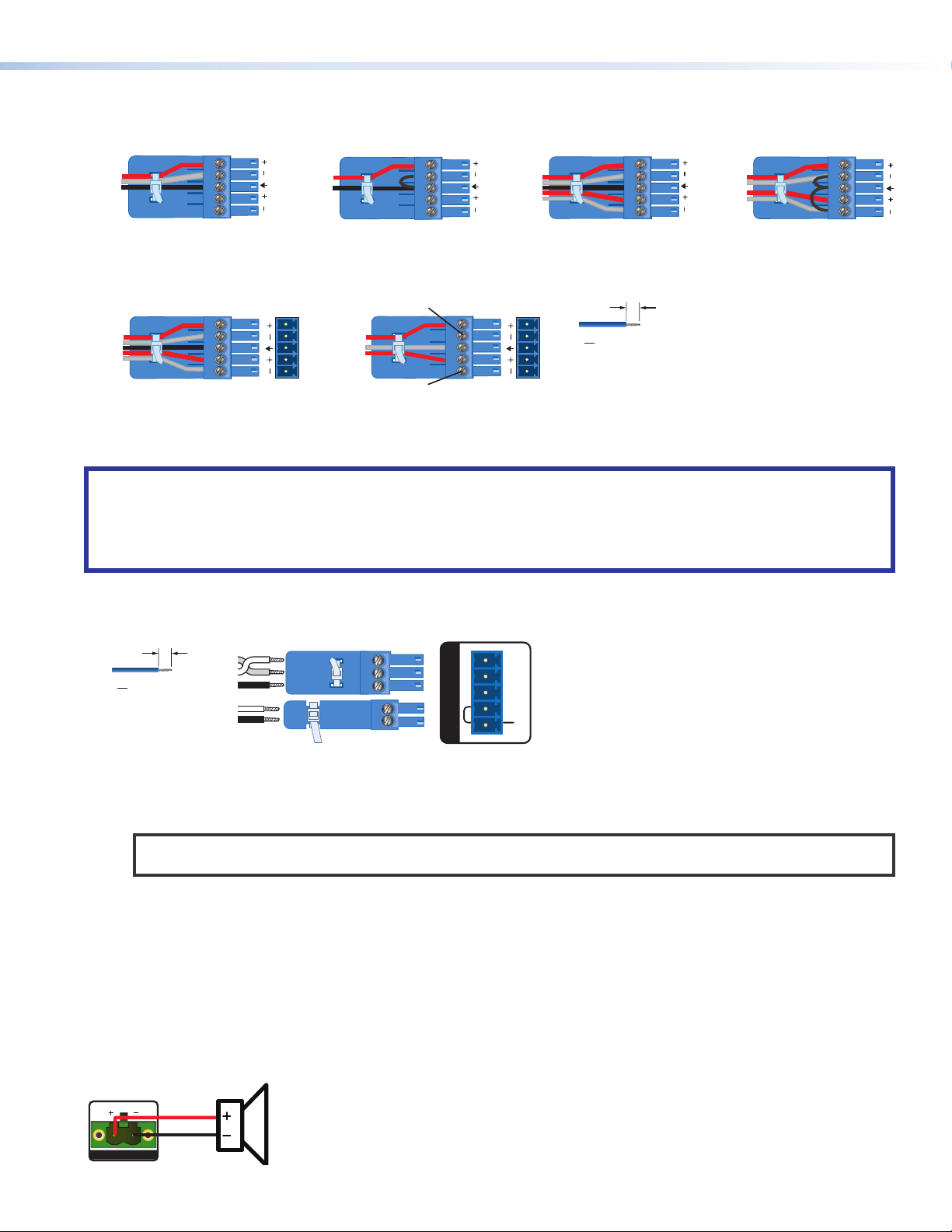
Step 2 — Captive Screw Audio Cable Wiring
12
Sleeves
Unbalanced Output
CH 1
Wire the captive-screw connectors to the input or output as shown in the following gures.
Tip
Ring
Sleeve
12
Tip
Sleeve
12
Tip
Ring
Sleeves
Tip
Ring
12
Tip
Sleeve
Tip
Sleeve
Balanced Mono Input
Tip
Ring
Tip
Ring
Balanced Output
Figure 3. Line Input and Line Output Wiring
ATTENTION:
• For unbalanced audio outputs, connect the sleeves to the ground contact. DO NOT connect the sleeves to the negative
(-) contacts.
• Pour l’audio asymétrique, connectez les manchons au contact au sol. Ne PAS connecter les manchons aux contacts
négatifs (–).
Step 3 — Remote Ports
3 "
(5 mm) MAX.
16
Do not tin
the wires!
STANDBY
Unbalanced Mono Input
No Ground Here
OUTPUT
12
Tip
Sleeve
Tip
No Ground Here
Balanced Stereo Input
OUTPUT
12
3 "
(5 mm) MAX.
16
Do not tin
the wires!
Unbalanced Stereo Input
RS-232
Tx Rx
G
STANDBY
G
Rx
Tx
G
G
REMOTE
Figure 4. Remote Volume Control and Standby Ports
• Standby mode is forced when the Standby pin is connected to the second G pin. The power LED on the front panel
lights amber when the amplier is in Standby mode, indicating that the amplier is still receiving power despite the fact
that it has turned off all the outputs.
NOTE: The enabling and disabling of the auto-standby timer is handled through SIS or DSP Configurator. For more
details, consult the NetPA U 8001 SUB User Guide.
• Connect a 3.5 mm, 3-pole captive screw connector to remotely control the volume via SIS commands, and connect a 3.5
mm, 2-pole captive screw to place the amplifier into Standby mode.
Protocol for the RS-232 port:
• 38,400 baud • 1 stop bit • 8 data bits • no parity
Step 4 — Speaker Wiring
Connect a 2-pin, 5 mm captive-screw connector for speaker output on the NetPA U 8001 SUB amplier. The port has a screw
ange to secure the plug to the connector (see figure 5 to learn how to wire the captive screw connector).
CLASS 2 WIRING
8Ω/4Ω
OUTPUTS
3
Page 4

12345678
RJ-45
Connector
Insert Twisted
Pair Wires
Pins:
A cable that is wired as TIA/EIA T568A at one
end and T568B at the other (Tx and Rx pairs
reversed) is a "crossover" cable.
T568B T568A
Crossover Cable
(for direct connection to a PC)
End 1 End 2
Pin Wire Color Pin Wire Color
1 white-orange 1 white-green
2 orange 2 green
3 white-green 3 white-orange
4 blue 4 blue
5 white-blue 5 white-blue
6 green 6 orange
7 white-brown 7 white-brown
8 brown 8 brown
NetPA U 8001 SUB • Setup Guide (Continued)
Figure 5. Speaker Output Port and Wiring Diagram
ATTENTION:
• You must use Class 2 wiring for this output to comply with UL requirements.
• Vous devez utiliser le câblage de classe 2 pour cette sortie an de vous conformer aux exigences UL.
• Do not tie channel output pins to each other or to ground. Doing so will short out the outputs, damage the
amplier, or both.
• Ne pas lier les sorties 1 et 2 des canaux entre elles ou à la terre. Les sorties pourraient être court-circuitées et/
ou l’amplicateur pourrait être endommagé.
• To avoid risk of damage to the amplier or the speakers, always check that speaker loads are appropriately
wired to the amplier.
• Pour éviter les risques de dommages à l’amplicateur ou aux haut-parleurs, vériez toujours que les charges
des haut-parleurs sont correctement câblées à l’amplicateur.
Step 5 — AT Port
Connect an RJ-45 connector to the AT port to connect and
communicate with the Dante network. It is also one of the
interfaces DSP Congurator uses to communicate with the
amplier. The Link LED indicates when a connection is made.
Go to Configure Dante Device Settings on page 5 for
information on Dante settings. See the image to the right for
wiring.
Step 6 — Powering on Amplifier and Adjustments
Ensure all sources connected to the amplier inputs are muted to
avoid potential speaker damage during power-up.
Reconnect all the power cables and switch on the rest of the
equipment before powering on the power amplier. The amplier
boots-up for up to 10 seconds as the front panel LED ashes green.
Once the boot-up sequence is complete, the amplier takes more time to sync with the Dante network, and begin the
playback of streamed content. The front panel LED lights green after approximately 20 seconds.
ATTENTION:
• The amplier must be powered on last.
• L’amplicateur doit être mis sous tension en dernier.
Step 7 — Checking LEDs
Check the Limiter/Protect and Signal LEDs on the front and rear panels to see if any problems are encountered (see “Front
Panel Features and Troubleshooting” in the NetPA U 8001 SUB User Guide for more information).
Double-check the correct load is connected and properly wired to the rear panel connection (see Speaker Wiring on page 3
for more information).
Step 8 — DSP Configurator Software Installation
There are no hardware controls for the NetPA U 8001 SUB. Conguration is performed using Extron DSP Congurator
software, while control is performed via SIS commands. To learn about full computer requirements, see the DSP Congurator
product page on www.extron.com.
Download DSP Configurator from the Extron Website
1. From the Extron home page (www.extron.com), click the Download tab to open the Download page.
2. Under Software (located on the left side of the page), select DSP Congurator Software. The DSP Configurator
3. Click the Download button and follow the on-screen instructions.
Software product page opens.
4
Page 5

NOTE: An Extron Insider account is required to download DSP Configurator.
Step 9 — NetPA U 8001 SUB Configuration
When power is connected to the unit and the rest of the audio system, audio output can be easily configured to any listening
environment via the DSP Configurator. The following steps detail how to configure a NetPA U 8001 SUB amplifier.
Configure the NetPA U 8001 SUB Amplifier
1. Ensure the control computer is
connected to either the AT port,
RS-232 port, or the rear panel USB
conguration port.
2. Start the DSP Congurator software.
From the splash screen drop-down list,
select NetPA U 8001 SUB. Click OK.
The main workspace opens.
3. The software starts in Emulate mode:
a. To create a conguration le ofine
and then upload that conguration
to a NetPA U 8001 SUB unit at a
later time, remain in Emulate mode and save the conguration le.
b. To upload a conguration to the NetPA U 8001 SUB unit or download the current conguration from the unit, enter Live
mode. When in Live mode, changes made in DSP Congurator immediately affect the connected NetPA U 8001 SUB. To
enter Live mode, click Live at the top of the DSP Congurator workspace, or select Tools > Connect to Device, or
press <F6> on the keyboard.
NOTE: When Live mode is selected, a connection dialog box appears. Select the desired connection type and follow
the on-screen prompts (see the NetPA U 8001 SUB User Guide for more information on connecting live to a device).
The main workspace provides access to mix matrices, gain blocks, and DSP processors (including a crossover lter)
for conguring a NetPA U 8001 SUB. It also provides a menu bar across the top with additional conguration tools. For
more information on using the DSP Congurator, see the “DSP Congurator” section of the NetPA U 8001 SUB User
Guide, or the DSP Configurator Help File that can be accessed by selecting Help > Contents or pressing <F1>. Most
dialog boxes within DSP Congurator contain a Help button ( ) in the top right corner. Click this button to open the
help le topic for that particular dialog box.
Downloading and Installing Dante Controller
1. From www.extron.com, hover over the Download tab at the top of the page.
2. From the Featured Software list, select Dante Controller. The Dante Controller product page opens.
3. Click the blue Download button.
4. Select Run to run the Dante Controller installer or select Save to save the install le to run at a later time.
5. If you choose to run the le, follow all prompts. If you saved the le, click the saved le to begin installation when ready.
NOTE: The installed Dante Controller program files are saved in:
C:\Program Files (x86)\Audinate\Dante Controller\DanteController.exe.
Configure Dante Device Settings
Dante settings in the NetPA U 8001 SUB can be congured from DSP Congurator. The device can be named in the Dante
Device Settings, which assists with identifying a specic device in the Dante Controller software when there are multiple
devices on the Dante network.
ATTENTION:
• It is crucial that a Dante device be named before audio subscriptions with other devices are established. Existing
• Il est crucial qu’un appareil Dante soit nommé avant la création d’abonnements audio avec d’autres appareils. Les
5
subscriptions are removed when a unit is renamed.
abonnements existants sont supprimés lorsqu’une unité est renommée.
Page 6

Ext
SF
Spea
Wallplate
NetPA U 8001 SUB • Setup Guide (Continued)
To configure Dante device settings:
1. Open DSP Congurator and connect live to the NetPA U 8001 SUB.
2. Select Tools > Device Settings. The Device Settings dialog box opens.
3. From the tabs at the top of the Device Settings dialog box, select Dante Device.
4. In the Device Name eld, give the NetPA U 8001 SUB a name (recommended to be device model and location) so that it can
be easily identied in Dante Controller. No spaces are allowed in the name.
5. Dante device network settings can also be congured in this dialog box. Use the radio buttons and text elds to choose
DHCP (recommended) or Static IP and enter a static IP address conguration.
6. Click Apply.
7. Click OK to conrm changes and close the Device Settings dialog box.
Renaming the NetPA U 8001 SUB Amplifier in Dante Controller
1. From the control computer Start menu select: All Programs > Audinate > Dante Controller > Dante
Controller
2. The Dante Controller - Network View screen opens. All Dante devices on the network are discovered and listed.
3. From the Device menu, select Device View or press <Ctrl+D> on the keyboard.
4. The Dante Controller - Device View dialog opens. Select the device being congured from the (Select a Dante
Device...) drop-down list. The Device View dialog populates with the selected NetPA U 8001 SUB information.
Figure 6. Populated Device View Dialog Box
5. Click the Device Cong tab to open the Device Config page.
6. In the Rename Device panel, enter the new name of the device in the text eld.
NOTE: No spaces are allowed in the name and names should be significant identifiers. For example,
7. Click Apply. A conrmation prompt opens.
8. Click Yes to conrm the new name.
9. Repeat as necessary for all devices.
NetPAUAmplifier-MainRack
Creating a Physical Dante Network
A physical network is required to share Dante audio channels
among Dante-enabled devices like those found in the NetPA
U 8001 SUB. Other devices capable of sending and receiving
audio over a Dante network must be on the same physical
network in order to communicate with Dante (see gure 7 on
the right for an example of a Dante network).
ron
26CT
kers
OVER
TEMP
21
LIMITER/PROTECT
SIGNAL
Extron
XPA U 1002-70V
Power Amplier
Audio
POWER AMPLIFIERS
XPA U 1002 SERIES
Audio Line Out
Extron
SF 10C SUB
Subwoofer
Ethernet
OVER
TEMP
LIMITER/PROTECT
SIGNAL
Extron
NetPA U 8001 SUB
Subwoofer Amplier
Extron
WPD 101 3.5 mm
Single Gang
Pass-Through
800 Watt @ 8Ω
NetPA U 8001 SUB
Line Inputs
AUDIO
Figure 7. Example of a Dante Network
6
Page 7

Dante Network Setup
Use a standard Ethernet cable to connect a NetPA U 8001 SUB amplier to a Dante network via the AT port. Launch the
Dante Controller program.
Dante Controller automatically discovers all Dante devices on the network and allows other Dante-enabled devices to
communicate with it. The default device name is the model name followed by the last six characters of the device MAC address
(for example, NetPA-U-xxxxxx). Multiple devices on the same network can present difculty in identifying inputs and outputs. To
avoid confusion, rename each device to a unique identier.
NOTE: To simplify setup, connect only one Dante device to the network at a time.
Dante Controller Operation
Dante Transmitters and Receivers
A Dante network is comprised of transmitters that output digital audio onto the Dante network and receivers that receive
digital audio input from the Dante network.
• Transmitters output digital audio from the device onto the audio network.
• Receivers take in digital audio from the audio network into the device.
Network View Layout
In the Dante Controller software, Dante transmitters are
listed horizontally across the top of the Network View
(1), while Dante receivers are listed vertically on the left
side of the window (2). Creating a link in the connection
matrix routes audio from a transmitter to a receiver (3).
Routing Devices
1. To show the transmitters of a Dante device, click
the + box next to the desired device in the Dante
Transmitters panel, such as
NetPA-U-Classroom-1 (1). The + changes to a –
sign when the details for the device expand.
2
1
3
2. To show the receivers of a Dante device, click the
+ box next to the desired device in the
Dante Receivers panel, such as DMP128P-PD-Control-Room (2).
3. Click the intersection of the desired subscription (discrete connection) between a transmitter and a receiver (
mark at the intersection indicates the subscription is made. A check mark also appears next to the receiver channel.
). A check
3
NOTE: A receiver can subscribe to only one transmitter. A transmitter can connect to multiple receivers.
4. To undo routing, click the junction again to disconnect the receiver from the transmitter.
NOTE: After making changes to Dante network routing such as subscriptions, device names, or channel labels, wait at
least 5 seconds before disconnecting or powering down the devices. This ensures that the new information is properly
saved to those devices. Device-level configurations, such as sample rates, latency, and clock settings are saved
instantly.
For more information on conguring a NetPA U 8001 SUB unit in Dante Controller, see the “Dante Controller” section of the
NetPA U 8001 SUB User Guide found on www.extron.com.
7
Page 8

NetPA U 8001 SUB • Setup Guide (Continued)
Gain Structure
The input sensitivity of the NetPA U 8001 SUB amplier is 0 dBFS. To achieve maximum output power without degrading audio
clarity, the peak signal level on the meter at the amplier channel output attenuators should be set at—or as close as possible—to
0 dBFS.
The default conguration of the DSP blocks are as follows:
• Input Signal Chain
• All analog input gains (ANG GAIN) are set to 0 dB.
• All Dante inputs do not have an input gain inserted.
• All processors are disabled.
• All input pre-mix gains are set to 0 dB.
• Mix Points
• Analog inputs are mixed at -6 dB to the amplier output channel and mixed at 0 dB to the AT outputs.
• AT inputs are mixed at -6 dB to the amplier output and at 0 dB to the Line outputs.
• Output Signal Chain
• All output trims are set to 0 dB.
• Amplier channel output attenuator is set to -24 dB.
• Line and AT output attenuators are set to 0 dB.
Setting-Up Gain Structure
Setting proper gain structure is necessary to ensure maximum audio clarity and amplier output performance. To set-up gain
structure, follow the steps outlined below, using a calibrated pink noise source.
1. Ensure all pre-mix gain and output trim blocks are set to 0 dB.
2. If mixing a stereo input to the subwoofer output, set mix point gain to -6 dB for each input channel. If mixing a mono input to
the amplier output, set mix point gain to 0 dB.
3. Adjust the Line Input ANG GAIN blocks so the output meter reads -17 dBFS.
4. Adjust the output attenuators, so the output meter reads -17 dBFS.
Refer to the NetPA U 8001 SUB User Guide found on www.extron.com for more details on setting-up gain structure.
NOTE: When setting levels, pay attention to avoid digital clipping.
Crossover Filter
One lter block is available for each output channel. This lter block offers a crossover lter that links the parameters of two (one
high-pass and one low-pass) or three (two high-pass and one low-pass) output lters. To apply a crossover lter to the output
channel, follow the procedure found in the NetPA U 8001 SUB User Guide.
For information on safety guidelines, regulatory compliances, EMI/EMF compatibility, accessibility, and related topics, see the
Extron Safety and Regulatory Compliance Guide on the Extron website.
© 2020 Extron — All rights reserved. www.extron.com
All trademarks mentioned are the property of their respective owners.
Worldwide Headquarters: Extron USA West, 1025 E. Ball Road, Anaheim, CA 92805, 800.633.9876
68-3414-50 Rev. A
11 2020
 Loading...