

Page 1
NetPA U 2002 SB
2-channel DSP and Dante-enabled
Audio Power Amplifier
User Guide
NetPA Ultra Series
68-3148-01 Rev. A
04 21
Page 2
Page 3
Copyright
© 2021 Extron. All rights reserved. www.extron.com
Trademarks
All trademarks mentioned in this guide are the properties of their respective owners.
The following registered trademarks (®), registered service marks (SM), and trademarks (TM) are the property of RGBSystems, Inc. or Extron (see the
current list of trademarks on the Terms of Use page at www.extron.com):
Registered Trademarks (
Extron, Cable Cubby, ControlScript, CrossPoint, DTP, eBUS, EDID Manager, EDID Minder, eLink, Flat Field, FlexOS, Glitch Free, GlobalConfigurator,
GlobalScripter, GlobalViewer, Hideaway, HyperLane, IPIntercom, IPLink, KeyMinder, LinkLicense, LockIt, MediaLink, MediaPort, NAV,
NetPA, PlenumVault, PoleVault, PowerCage, PURE3, Quantum, ShareLink, Show Me, SoundField, SpeedMount, SpeedSwitch, StudioStation,
SystemINTEGRATOR, TeamWork, TouchLink, V-Lock, VideoLounge, VN-Matrix, VoiceLift, WallVault, WindoWall, XPA, XTP, XTPSystems, and ZipClip
Registered Service Mark
(SM)
: S3 Service Support Solutions
Trademarks (™
AAP, AFL (Accu-RATEFrameLock), ADSP(Advanced Digital Sync Processing), AVEdge, CableCover, CDRS(ClassD Ripple Suppression),
CodecConnect, DDSP(Digital Display Sync Processing), DMI (DynamicMotionInterpolation), DriverConfigurator, DSPConfigurator, DSVP(Digital
Sync Validation Processing), EQIP, Everlast, FastBite, Flex55, FOX, FOXBOX, IP Intercom HelpDesk, MAAP, MicroDigital, Opti-Torque,
PendantConnect, ProDSP, QS-FPC(QuickSwitch Front Panel Controller), RoomAgent, Scope-Trigger, SIS, SimpleInstructionSet, Skew-Free,
SpeedNav, Triple-Action Switching, True4K, True8K, Vector™ 4K, WebShare, XTRA, and ZipCaddy
®
)
)
Page 4

FCC Class B Notice
NOTE: This device complies with part 15 of the FCC rules. Operation is subject to the
This equipment has been tested and found to comply with the limits for a Class B digital
device, pursuant to part15 of the FCC rules. These limits provide reasonable protection
against harmful interference in a residential installation. This equipment generates, uses,
and can radiate radio frequency energy and, if not installed and used in accordance with
the instructions, may cause harmful interference to radio communications. There is no
guarantee that interference will not occur. If this equipment does cause interference to radio
or television reception, which can be determined by turning the equipment off and on, you
are encouraged to try to correct the interference by one or more of the following measures:
• Reorient or relocate the receiving antenna.
• Increase the separation between the equipment and receiver.
• Connect the equipment into an outlet on a circuit different from that to which the
receiver is connected.
• Consult the dealer or an experienced radio/TV technician for help.
In order to maintain compliance with FCC regulations, shielded cables must be used with
this equipment. Operation with non-approved equipment or unshielded cables is likely to
result in interference to radio and TV reception. The user is cautioned that changes and
modifications made to the equipment without the approval of the manufacturer could void
the user’s authority to operate this equipment.
following two conditions: (1) This device may not cause harmful interference, and (2)
This device must accept any interference received, including interference that may
cause undesired operation.
NOTE: For more information on safety guidelines, regulatory compliances, EMI/EMF
compatibility, accessibility, and related topics see the Extron Safety and Regulatory
Compliance Guide on the Extron website.
Page 5
Conventions Used in this Guide
Notifications
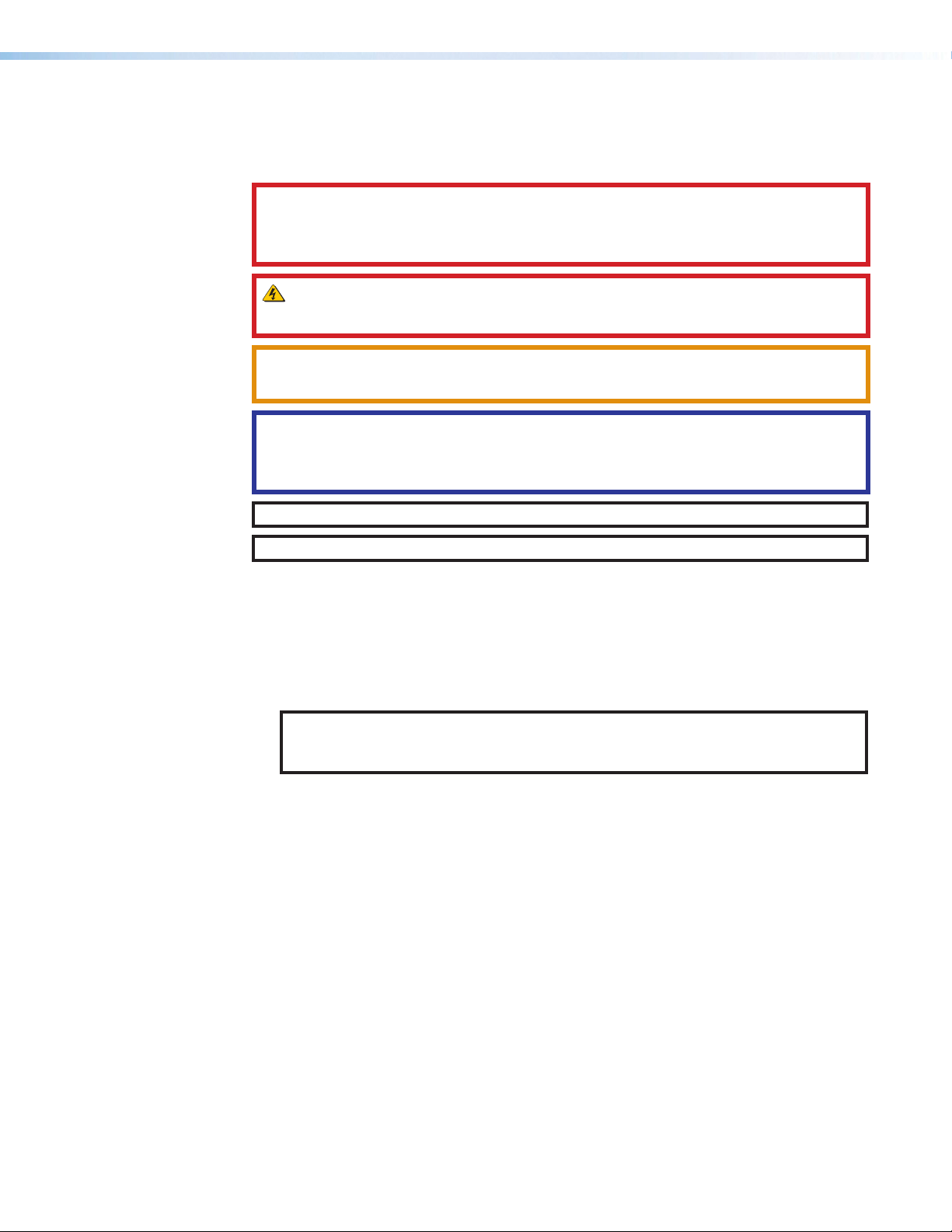
The following notifications are used in this guide:
DANGER:
• Will result in serious injury or death.
• Entraînera des blessures graves ou la mort.
WARNING: Potential risk of severe injury or death.
AVERTISSEMENT : Risque potentiel de blessure grave ou de mort.
CAUTION: Risk of minor personal injury.
ATTENTION : Risque de blessuremineure.
ATTENTION:
• Risk of property damage.
• Risque de dommages matériels.
NOTE: A note draws attention to important information.
TIP: A tip provides a suggestion to make working with the application easier.
Software Commands
Commands are written in the fonts shown here:
^AR Merge Scene,,Op1 scene 1,1 ^B 51 ^W^C
[01] R 0004 00300 00400 00800 00600 [02] 35 [17] [03]
E X! *X1&* X2)* X2#* X2! CE}
NOTE: For commands and examples of computer or device responses mentioned
in this guide, the character “0” is used for the number zero and “O” is the capital
letter “o.”
Computer responses and directory paths that do not have variables are written in the font
shown here:
Reply from 208.132.180.48: bytes=32 times=2ms TTL=32
C:\Program Files\Extron
Variables are written in slanted form as shown here:
ping xxx.xxx.xxx.xxx —t
SOH R Data STX Command ETB ETX
Selectable items, such as menu names, menu options, buttons, tabs, and field names are
written in the font shown here:
From the File menu, select New.
Click the OK button.
Specifications Availability
Product specifications are available on the Extron website, www.extron.com.
Extron Glossary of Terms
A glossary of terms is available at http://www.extron.com/technology/glossary.aspx.
Page 6

Page 7

Contents
Introduction ................................................1
About This Guide ................................................. 1
About the NetPA U 2002 SB ............................... 1
Features .............................................................. 1
Installation .................................................. 4
Mounting the NetPA U 2002 SB Amplifier ............ 4
Tabletop Use ................................................... 4
UL Rack Mounting Guidelines .......................... 4
Rack Mounting .................................................... 5
Rack Ear Mounting .......................................... 5
Bridge Plate Rack Mounting ............................ 5
Rack Shelf Mounting ........................................... 6
Rack Mounting Ventilation Recommendations . 7
Flexible Conduit Adapter Kit Installation ............... 8
UL Requirements ............................................. 9
Installing the Flexible Conduit Adapter Kit ........ 9
Installing the SAK AMP SF 10C Mounting Kit
for NetPA U Amplifiers .................................. 11
Operation.................................................. 16
Front Panel Features .......................................... 16
Rear Panel Features .......................................... 17
Operation .......................................................... 21
Default ........................................................... 21
AT Port .......................................................... 22
Standby Modes ............................................. 22
Monitoring ..................................................... 24
DSP Configurator Software .......................26
Downloading and Installing DSP Configurator .... 26
Accessing the DSP Configurator Help File ......... 27
DSP Configurator Main Workspace ................... 27
Menu Bar ...................................................... 27
Presets Drop-Down ....................................... 30
DSP Configurator Status Panel ...................... 30
Live and Emulate Panel.................................. 30
Connect to a NetPA U 2002 SB Amplifier
in Live Mode ................................................. 31
Exit Live Mode and Enter Emulate Mode........ 33
DSP Configurator Inputs .................................... 34
Mic/Line Inputs .............................................. 34
Mic/Line Inputs Processing ............................ 36
AT Inputs ....................................................... 45
AT Inputs Processing ..................................... 45
Mix-Points ......................................................... 46
DSP Configurator Outputs ................................. 48
Line/AT Outputs ............................................. 48
Line/AT Output Processing ............................ 50
Balancing NetPA Amplifier Output Level
and XPA Input Sensitivity .................................. 53
Amplifier Outputs ............................................... 54
Setting the Output Mode ............................... 54
Configuring the Output Mode ........................ 55
Naming an Amplifier Output ........................... 56
Amplifier Outputs Processing ......................... 56
Monitoring ......................................................... 57
Open Circuit Detect ....................................... 61
Loss of AC..................................................... 61
Configuration Tools ................................... 63
Presets .............................................................. 63
Methods for Marking Items ............................ 63
Configuring Presets ....................................... 64
Groups .............................................................. 65
Configuring Groups ....................................... 66
Device Manager ................................................ 67
Managing Devices in Device Manager ............ 68
Connect/Disconnect from Device ...................... 69
Firmware Loader ............................................... 70
Downloading Firmware Updates .................... 70
Organize Building Blocks ................................... 71
Device Settings.................................................. 72
Unit Info ......................................................... 72
Serial Settings ............................................... 73
Dante Device .................................................... 73
Options ............................................................. 74
viiNetPA U 2002 SB User Guide • Contents
Page 8

Dante Controller ........................................75
Overview ........................................................... 75
Downloading and Installing Dante Controller ...... 76
Configuring a NetPA U 2002 SB Amplifier
in Dante Controller ............................................ 76
Device Name ................................................. 76
Receiver and Transmitter Names ................... 77
Dante Controller Naming Conventions ........... 77
Renaming the NetPA U 2002 SB Amplifier
in Dante Controller ........................................ 77
Renaming a Receiver or Transmitter............... 79
Finding a Dante Device IP Address ................ 80
Dante Controller Operation ................................ 81
Dante Transmitters and Receivers .................. 81
NetPA Ultra Series Transmitters and
Receivers...................................................... 81
Dante Routing Operation ............................... 81
Routing Devices ................................................ 81
Disconnecting Inputs from Outputs ................ 83
Dante Troubleshooting ....................................... 83
Simplifying the Network for Troubleshooting... 83
Troubleshooting the Network Interface ........... 83
Restarting Dante Controller ............................ 84
AT Port .......................................................... 86
USB Config Port ............................................ 87
Verbose Modes ............................................. 87
Host-to-Device Communications ....................... 87
NetPA U 2002 SB-initiated Messages ............ 87
Using the Command and Response Tables ....... 88
Symbol Definitions ......................................... 88
Error Responses ............................................ 88
Hardware Reset Modes ..................................... 89
Command and Response Table ......................... 90
Object ID (OID) Number Tables ........................ 103
Input Path OIDs ........................................... 103
Output Path OIDs ........................................ 103
Mix-point OIDs............................................. 104
Troubleshooting ............................................... 104
Amplifier Fails to Exit Standby Mode
Promptly ..................................................... 104
Amplifier Enters Standby Mode Too Early ..... 105
Limiter/Protect LED Warning Indicators........ 105
Over Temp Indicator LED ............................. 105
Status Commands ....................................... 106
Extron Warranty ......................................108
Remote Communication and Control .........85
Connection Options ........................................... 85
RS-232 Port .................................................. 86
NetPA U 2002 SB User Guide • Contents viii
Page 9

Introduction
This section gives an overview of the Extron NetPA U 2002 SB 2-channel power amplifier.
Topics in this section include:
• About This Guide
• About the NetPA U 2002 SB
• Features
About This Guide
This guide describes the NetPA U 2002 SB: a 2-channel DSP-enabled power amplifier, and
discusses how to install, configure, and operate it.
In this guide, the terms “unit,” “amplifier,” and “power amplifier” refer to the NetPA U 2002
SB power amplifier.
About the NetPA U 2002 SB
Features
The Extron NetPA U 2002 SB is an ENERGY STAR qualified, Dante-enabled audio power
amplifier with flexible outputs that can drive 8 ohm, 4 ohm, 70 volt, or 100 volt loads in a half
rack, convection cooled, plenum rated enclosure that includes rack mount hardware.
The bridgeable outputs can deliver two 200 watt channels into low impedance systems or
one 400 watt channel into low or high impedance systems. Onboard audio DSP includes
a 6x6 mix matrix, filters, and dynamics. Four mic/line inputs and two line outputs can be
utilized as Dante endpoints or as additional inputs to the onboard DSP. System monitoring
via the Dante connection includes detailed amplifier status.
The NetPA U 2002 SB features Extron’s patented highly efficient Class D amplifier design
with CDRS – Class D Ripple Supression, and defeatable auto-standby with fast wake up.
• Receives audio from the Dante audio network as well as from analog
mic/line level inputs — Select a channel from any remote Dante-enabled device
on the network, or an analog source, to be brought into the NetPA U 2002 SB for
amplification.
• Two channels with selectable output modes — Allows this single amplifier model to
be used in a wide variety of system configurations. Available configurations per channel
pair:
• Two 200 watt channels into 8 ohms or 4 ohms
• One 400 watt bridged channel into 70V or 100V
• One 400 watt bridged channel into 8 ohms or 16 ohms
NetPA U 2002 SB User Guide • Introduction 1
Page 10

• ENERGY STAR qualified amplifier with defeatable auto-standby and fast wake
up — The NetPA U 2002 SB is an ENERGY STAR qualified amplifier and energy
efficient product that conserves energy and reduces cost. It meets ENERGY STAR
qualification requirements with an auto-standby feature which automatically places the
amplifier into Standby Mode after 25 minutes of inactivity thereby dramatically reducing
power consumption. It quickly returns to full power status in less than 100 ms upon
signal detection, with minimal inrush current. Auto-standby can be disabled if required.
• Single and dual rack-mount hardware included — The included single and side-by-
side rack-mount hardware simplifies planning and saves cost.
• Integrated DSP — The NetPA U 2002 SB has a 6x6 mix matrix which provides
essential DSP processing including level control, filters, dynamics, ducking, and delay.
• Convection cooled, fanless operation - can be stacked without extra rack
space for ventilation — The NetPA U 2002 SB does not require internal fans or vents
for cooling, ensuring quiet and reliable operation. It generates substantially less heat
than conventional power amplifiers, making it ideal for rack-mount applications where
space is limited (see Rack Mounting Ventilation Recommendations on page7).
• Extron Patented CDRS - Class D Ripple Suppression — CDRS is an Extron
Patented technology that provides a smooth, clean audio waveform and an
improvement in signal fidelity over conventional Class D amplifier designs. CDRS
eliminates the high frequency switching ripple that is characteristic of Class D amplifiers,
a source of RF emissions which can interfere with sensitive AV equipment such as
wireless microphones.
• Remote control and monitoring —
• Control and monitor the NetPA U 2002 SB amplifier directly through the RS-232
port.
• Control the NetPA U 2002 SB amplifier through a DMP Plus or XMP processor over
a Dante network.
• Setup and configuration with Extron DSP Configurator Software — Via the Dante
network or USB.
• UL 2043 plenum rated when used with optional Flexible Conduit Adapter Kit —
The NetPA U 2002 SB meets UL 2043 for smoke and heat release for installation within
a plenum airspace above a drop ceiling when used with the optional Flexible Conduit
Adapter Kit. Above-the-ceiling placement conceals the amplifier to prevent theft, and is
convenient for installing equipment when space inside the room is limited.
• Professional grade signal-to-noise and THD+N performance — The NetPA U
2002 SB delivers professional grade performance, featuring 100 dB signal-to-noise ratio
and THD+N of less than 0.1%.
• Ultra low inrush current at power up - no need for power sequencing —
Allows multiple NetPA U 2002 SB amplifiers to be powered on simultaneously without
overloading power circuits. This eliminates the need for power sequencing.
• Power factor correction - removes harmonic content on AC line — The NetPA
U 2002 SB features power factor correction technology that smooths out the high
peak currents of the amplifier’s current draw thereby minimizing the presence of high
frequency harmonics on the AC power line and preventing audible artifacts from being
transmitted to other audio equipment in the system.
• Automatic clip limiter — Detects actual onset of clipping. Gain is automatically
reduced without audible artifacts to protect speakers from clipping distortion.
• Multiple protection circuits — Activate during output shorts, thermal overload, or DC
faults to prevent damage to the amplifier and speakers.
NetPA U 2002 SB User Guide • Introduction 2
Page 11

• Remote standby port — Enables the NetPA U 2002 SB to be remotely powered
down when not in use, reducing operating cost.
• High pass filter for high impedance models — The NetPA U 2002 SB features
a fixed high pass filter on the amplified outputs to prevent saturation of speaker
transformers.
• 5 mm screw-lock captive screw speaker connectors — Enable simple, secure
connections with 22 to 12 AWG speaker cables.
• Front and rear-mounted signal and protection indication LEDs — Provide
convenient indication of input signal presence and protection circuit activation from both
sides of the equipment rack.
• Front panel over-temperature LED — Provides visual indication that the amplifier
temperature has exceeded the optimal value, well in advance of the onset of thermal
protection circuitry.
• Internal Extron Everlast power supply — Provides worldwide power compatibility,
with high-demonstrated reliability and low power consumption for reduced operating
cost.
• Extron Everlast Power Supply is covered by a 7-year parts and labor warranty.
NetPA U 2002 SB User Guide • Introduction 3
Page 12

Installation
This section describes the installation and setup of the NetPA U 2002 SB power amplifier. Topics
include:
• Mounting the NetPA U 2002 SB Amplifier
• Rack Mounting
• Flexible Conduit Adapter Kit Installation
Mounting the NetPA U 2002 SB Amplifier
The NetPA U 2002 SB amplifier can be mounted in a rack using the included rack
ears, mounted on a rack shelf, set on a table or mounted in the plenum space above a
ceiling-mounted projector. Also, two amplifiers can be connected using the bridging plate to
create a full rack-width unit.
Tabletop Use
Four self-adhesive rubber feet are included. Attach one foot at each corner on the bottom
side of the amplifier and place the unit in a desired location.
UL Rack Mounting Guidelines
The following Underwriters Laboratories (UL) guidelines pertain to the safe installation of the
equipment in a rack.
• Elevated operating ambient temperature — If the equipment is installed in a closed
or multi-unit rack assembly, the operating ambient temperature of the rack environment
may be greater than room ambient temperature. Therefore, install the equipment in an
environment compatible with the maximum ambient temperature (TMA = +32° F to
+122° F (0° C to +50° C)/ 10% to 90%, noncondensing) specified by Extron.
• Reduced air flow — Install the equipment in a rack so the amount of air flow required
for safe operation of the equipment is not compromised.
• Mechanical loading — When mounting the equipment in the rack, ensure uneven
mechanical loading does not cause a hazardous condition.
• Circuit overloading — When connecting the equipment to the supply circuit, consider
the effect circuit overloading might have on overcurrent protection and supply wiring.
Consider equipment nameplate ratings when addressing this concern.
• Reliable earthing (grounding) — Maintain reliable grounding of rack-mounted
equipment. Pay particular attention to supply connections other than direct connections
to the branch circuit (for example, using power strips).
NetPA U 2002 SB User Guide • Installation 4
Page 13
Rack Mounting
Rack Ear Mounting
The NetPA U 2002 SB amplifier can be mounted onto a rack using one of the following
methods.
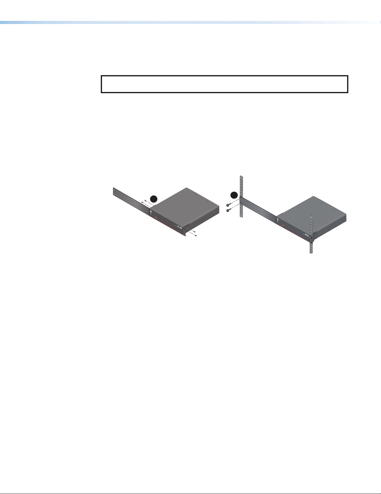
NOTE: The following figures show the NetPA U 2002 SB being installed; however, all
XPA Ultra and NetPA Ultra Series amplifiers are installed in the same way.
The NetPA U 2002 SB amplifier ships with a set of rack ears, so that the half rack-width
amplifiers can be installed in a full rack-width space.
Mount the amplifier with the rack ears by doing the following:
1. Remove the rubber feet from the bottom of the amplifier if previously installed.
2. Attach the included rack ears (one long and one short) to the sides of the amplifier with
the four provided #6 machine screws (see figure1,
1
).
1
OVE
R
TEMP
NetP
e
1
2
LIMI
TER/PROTECT
SIGNAL
NetP
POWER A
MPLIFIERS
N
e
t
P
A U
2
0
0
2 S
B
P
O
W
E
R
AMP
LIFIE
R
NetP
S
2
OVE
R
T
E
M
P
e
1 2
LI
M
I
TER
/
SI
P
RO
G
N
T
A
E
L
CT
NetP
P
O
W
E
R
AMP
L
IFIE
R
S
NetPA U 2002 SB
Figure 1. Installing the NetPA U 2002 SB
3. Insert the amplifier into the rack and align the holes in the rack ear with the holes on the
rack.
4. Secure the amplifier to the rack using the four provided 10-32 x 3/4” screws (2).
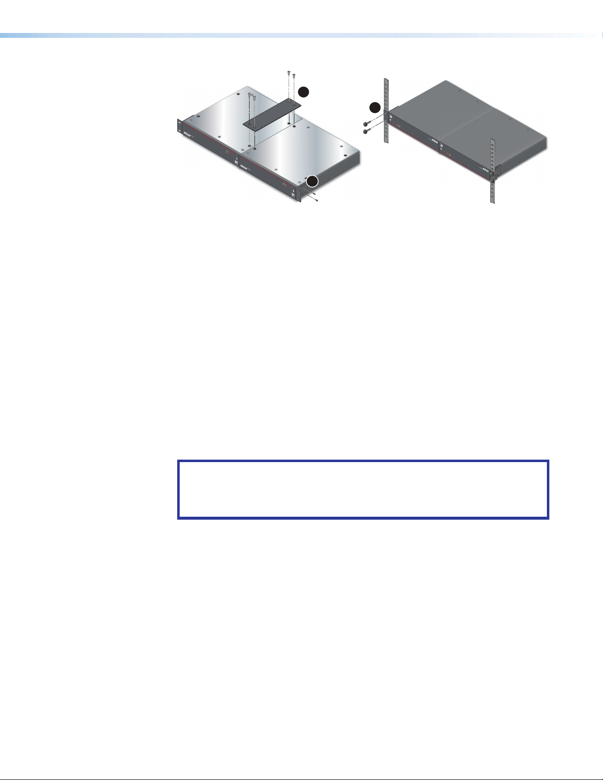
Bridge Plate Rack Mounting
The NetPA U 2002 SB amplifier ships with a bridge plate connector to allow two amplifiers
to be connected together and form a full rack-width unit.
Mount two NetPA U 2002 SB amplifiers by doing the following:
1. If the rubber feet are installed on the bottom of the amplifier, remove them.
2. Position two amplifiers upside down and next to each other.
3. Use the bridge plate connector and the four provided #4 machine screws to connect
the two amplifiers together (see figure2 on page6, 1).
4. Attach the two short rack ears to the amplifiers with the four provided #6 machine
screws (2).
NetPA U 2002 SB User Guide • Installation 5
Page 14
e
ES
R
S
Rack Shelf Mounting
Mounting
screws (4)
1
3
OV
O
VE
ER
TEM
R
T
E
M
P
P
e
e
1 2
S
4 SERIE
00
1
U
NetPA U 2002 SB
XPA
S
RS
R
E
I
F
I
IFIE
AMPL
R AMPL
R
E
W
O
POWE
P
NetP
CT
E
OT
IGNAL
S
CT
L
ER/PR
E
NA
G
IMIT
ROT
L
P
SI
ITER/
M
LI
4
1 2
1 2 3
e
e
P
M
E
T
R
TEMP
R
VE
OVE
O
RIES
SE
04
U 10
NetPA U 2002 SB
XPA
S
R
AMPLIFIE
R
WE
O
P
NetP
T
C
L
E
A
T
N
G
RO
P
SI
/
R
ITE
M
LI
2
2
1
e
P
M
E
T
R
OVE
1
2
3
4
L
I
M
ITER/
LIMITER
SI
P
R
G
OT
NA
E
L
C
/PROTEC
SIG
T
NAL
T
NetP
P
POWE
O
WE
R
R A
AM
M
P
P
LIF
LIFI
IE
ERS
R
S
X
NetPA U 2002 S
P
A U 1004 SERIES
OVE
O
B
VER
R
T
TEM
E
M
P
P
e
e
1 2
1 2 3 4
LI
M
IT
E
R/
SI
P
L
IM
ROT
G
N
I
T
A
E
E
L
R
C
/P
T
S
I
R
G
OTE
N
AL
C
T
NetP
P
O
W
E
R
AM
P
L
IF
IE
R
S
NetP
A U
2002
SB
Figure 2. Installing NetPA U 2002 SB Bridge Plate
5. Insert the amplifiers into the rack and align the holes in the rack ears with the holes in
the rack.
6. Secure the amplifiers to the rack using the four provided 10-32 3/4” screws (see
figure2, 3).
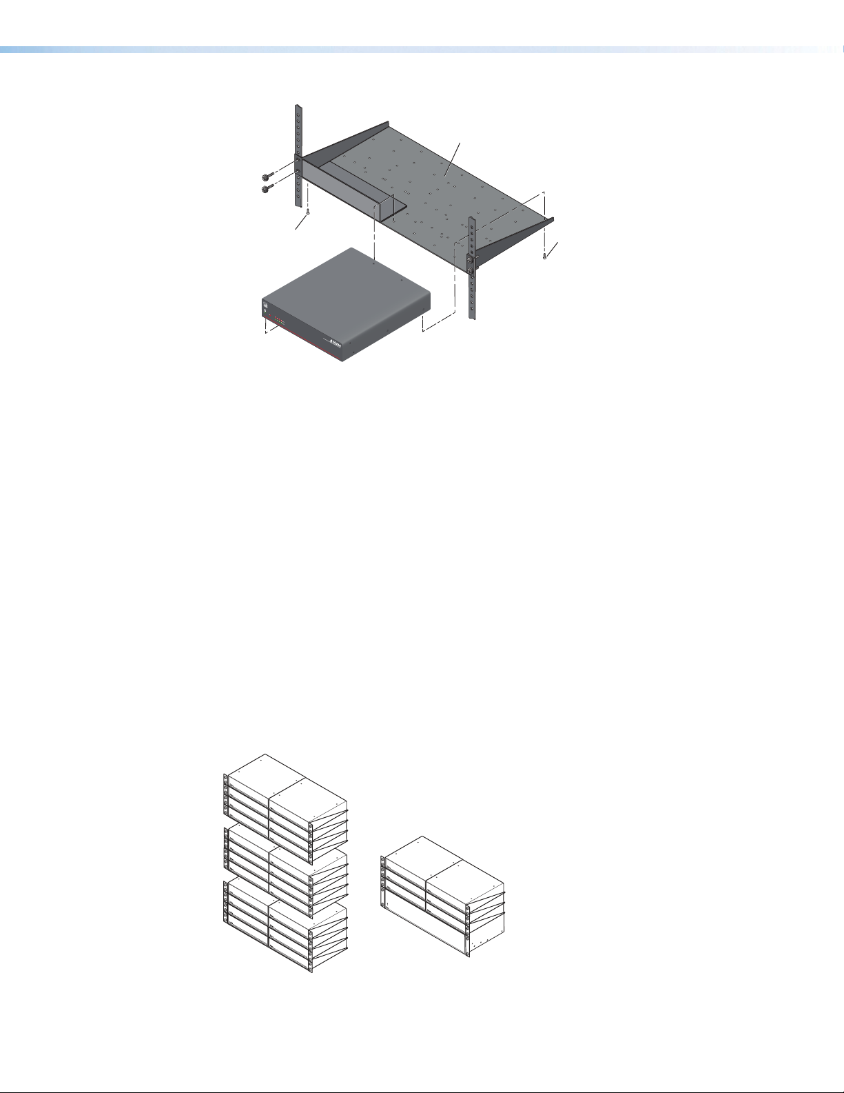
The NetPA U 2002 SB can be mounted on a shelf using the optional RSU 129 1U Universal
Rack Shelf Kit.
Mount the amplifier with the shelf as follows:
1. If the rubber feet are installed on the bottom of the amplifier, remove them.
2. Place the amplifier on one half of the rack shelf (see figure3 on page7).
3. Align the front of the amplifier with the front of the shelf, and align the threaded holes on
the bottom of the amplifier with the holes in the rack shelf.
4. Attach the amplifier to the rack shelf with the two provided 4-40 x 3/16” machine
screws. Insert the screws from the underside of the shelf and fasten them into
diagonally opposite corners.
ATTENTION:
• Using screws longer than 3/16” damages the unit and voids the warranty.
• L’utilisation de vis plus longues que 3/16” endommagera l’unité et annulera la
garantie.
NetPA U 2002 SB User Guide • Installation 6
Page 15
RSU 129
1U Universal Rack Shelf
False faceplate
uses 2 screws.
OVER
TEM
P
e
1
2 3 4
LIM
I
T
ER/P
SI
R
GNA
O
T
EC
L
T
NetP
P
O
W
E
R
AMP
L
IF
IE
R
S
4 SERI
E
S
Use 2 mounting holes
on opposite corners.
N
et
P
A
U 1
00
(2) 4-40 x 3/16"
Screws
Figure 3. Mounting the Amplifier onto a Rack Shelf
5. Attach the false front panel, which is provided with the rack shelf, to the unoccupied
side of the rack, or install a second half rack-width device to that side.
Repeat steps 1 through 5 if a second device is being installed.
6. Attach the rack to the shelf by using the four 10-32 x 3/4” screws provided with the
shelf. Insert the screws through #10 beveled washers, then through the holes in the
rack (see figure3).
Rack Mounting Ventilation Recommendations
Excessive heat decreases the optimal lifetime of the power amplifier. An Over Temp indicator
LED on the front panel of the amplifier lights red whenever the recommended operating
temperature has been exceeded.
The NetPA U 2002 SB amplifier needs to be arranged in a rack so that the environment
around the amplifier does not reach or go beyond +122 °F (+50 °C). No more than four
amplifiers should be stacked one-on-top-of-the-other without an open space in between, as
seen in figure4.
The NetPA U 2002 SB amplifier can be arranged above or below another non-NetPA Ultra
device. The environment around the amplifier should not reach or go beyond +122 °F
(+50°C).
Vent Space
Vent Space
Vent Space
Vent Space
Vent Space
Figure 4. Ventilation
Vent Space
Vent Space
NetPA U 2002 SB User Guide • Installation 7
Page 16

Flexible Conduit Adapter Kit Installation
The kit provides a way to replace the IEC power cord with a conduit, where required by local
codes.
The optional Flexible Conduit Adapter Kit includes the following parts:
• One conduit adapter plate (pre-attached), for PS 124 and XPA 1002/2001 amplifiers
• One conduit adapter plate for XPA Ultra Series and NetPA Ultra Series amplifiers (not
attached)
• One 6-foot long electrical conduit
• Three 7.5-foot 18-gauge power wires with spade connectors
• One UL rated zip tie wrap
• Three auxiliary crimp style spade connectors designed for 14- to 16-gauge wires
NOTES:
• If needed, Extron recommends using a UL-Listed crimp tool to terminate the
spade connectors. One recommended choice is a Molex crimp tool.
• The UL Listed electrical distribution box is not included with the NetPA Ultra
amplifier, the PS 124 power supply, or the Flexible Conduit Adapter Kit. The
installer is responsible for obtaining and installing the distribution box.
WARNING:
AVERTISSEMENT :
• The circuit breaker used for this connection should be rated no lower than 20
amps and no greater than 30 amps.
• Le disjoncteur utilisé pour cette connexion devrait avoir une cote comprise entre
20 et 30 amps.
• This unit must be installed in accordance with the National Electrical Code and
with all local codes.
• Cet appareil doit être installé conformément au National Electrical Code et à tous
les codes locaux.
• An all-pole mains switch with a contact separation of at least 3mm in each
pole shall be incorporated in the electrical installation of the building, The
installation shall be carried out in accordance with all applicable installation rules.
• Un interrupteur omnipolaire avec une séparation contact d’au moins
3mm dans chaque pôle, devra être incorporée dans l’installation électrique
du bâtiment. L’installation doit être réalisée conformément à toutes les règles
d’installation applicables.
• Installation and service must be performed by a qualified electrician only.
• L’installation et l’entretien doivent être effectués uniquement par un électricien
qualifié.
• Make sure the source device and the NetPA Ultra are turned off and
disconnected from the power source before you begin.
• Vérifiez que l’appareil source et le périphérique source sont éteints et
déconnectés de la source d’alimentation avant de commencer.
• To reduce the risk of fire or electric shock, do not expose this apparatus to rain or
moisture.
• Afin de réduire les risques d’incendie ou de choc électrique, protégez cet appareil
de la pluie ou de l’humidité.
NetPA U 2002 SB User Guide • Installation 8
Page 17
WARNING:
1
2
NetPA U 2002 SB
MIC/LINE INPUTS
1 2
1 2
STANDBY
CLASS 2
WIRING
LIMITER/PROTE
CT
SIGN
A
L
STE
RE
O
R
21
Tx
Rx
RS-2
3
2
G G
3 4
1
0
0-2
4
0V
1.0
A, 5
0
-
60Hz
LINE
OUTPUTS
CONFIGREMOTE
LINK
AT
OUTPUT MODE
OUTPU
TS
+
BR
-
8Ω/16
Ω
8Ω/4Ω
70V
100V
BRIDG
ED
MONO
Remove (10)
screws.
Slide cover forward and
lift straight up.
AVERTISSEMENT :
• The product is a Class I product, which must be connected only to a mains
• Ce produit est un produit de Classe I, qui doit être connecté seulement à une
• The mains plug/appliance coupler is used as the disconnect device and shall
• La fiche secteur / le coupleur d’appareil est utilisé comme dispositif de
• A UL-Listed electrical distribution box is recommended for the termination of the
• Un boîtier de distribution électrique certifié UL est recommandé pour la
UL Requirements
The Underwriters Laboratories (UL) requirements listed below pertain to the installation of
the flexible conduit onto an NetPA Ultra series power amplifier or a PS 124 power supply.
• This unit must not be used beyond its rated voltage range.
• This unit must be wired to a UL-Listed distribution box.
socket outlet with a protective earthing (grounding) connection.
prise femelle secteur équipée d’une connexion de mise à la terre.
remain readily operable.
déconnexion et doit rester facilement utilisable.
conduit opposite the PS 124 power supply or the NetPA Ultra amplifier. See UL
Requirements.
terminaison du conduit à l’opposé de l’alimentation PS 124 ou de l’amplificateur
NetPA Ultra. Voir UL Requirements.
Installing the Flexible Conduit Adapter Kit
WARNING: Electrostatic discharge (ESD) can damage IC chips even though you cannot
feel it. You must be electrically grounded before touching anything inside the NetPA
Ultra. A grounding wrist strap is recommended.
ADVERTISSEMENT : Les décharges électrostatiques peuvent endommager les puces
de circuit même si vous ne pouvez pas les sentir. Vous devez être électriquement relié
à la terre avant de toucher un élément à l’intérieur du NetPA Ultra. Un braceletde
mise à la terreest recommandé.
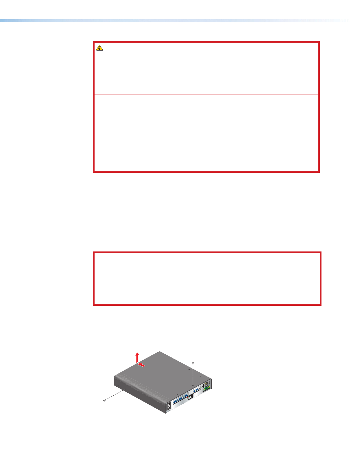
Install the flexible conduit to the NetPA U 2002 SB amplifier as follows:
1. Unplug the IEC power cord from the amplifier.
2. Remove the ten screws from the top, sides, and bottom of the amplifier, then slide and
lift the cover off (see figure5).
Figure 5. Removing the Cover
NetPA U 2002 SB User Guide • Installation 9
Page 18
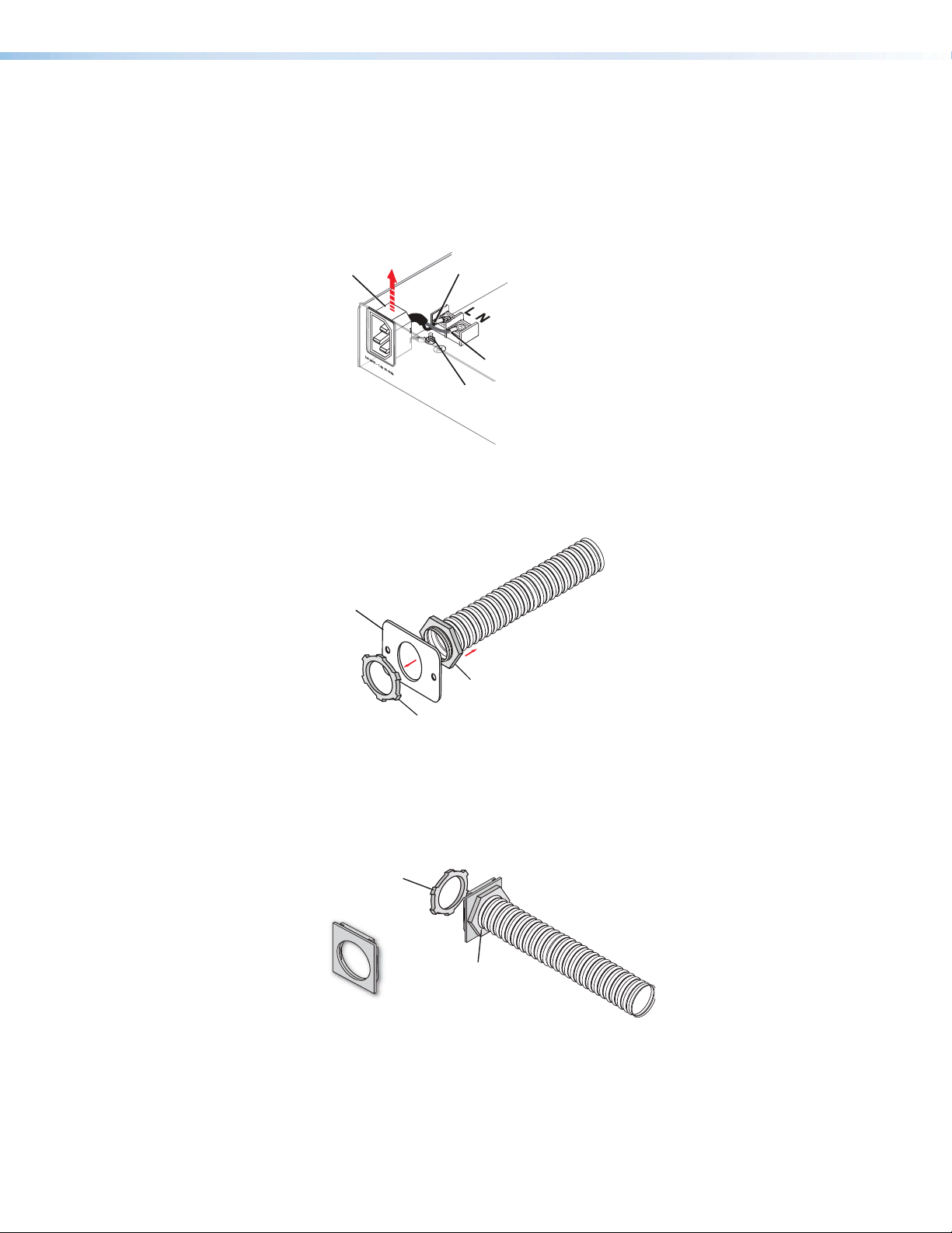
3. Remove the two screws holding the blue hot (line) and the brown neutral wires from the
Disconnect cables
and r
connector
e
Washer-B
Place the adapter plate
terminal block on the PCB. Put the screws to the side to be used later (see figure6).
4. Remove the ground wire nut from the grounding stud located on the bottom of the
enclosure, as shown below. Place the wire nut with the other screws to be used later.
5. Remove the wires attached to the IEC connector from the body of the amplifier, and
slide the IEC connector and attached wires up and out of the amplifier enclosure.
emove IEC
.
Blue Wire
Brown Wir
Remove nut
Figure 6. Removing the IEC Connector
6. Remove the washer at the end of the conduit (Washer-B), and remove the conduit
adapter plate that ships attached to the conduit.
Separate adapter plate
and washer from conduit
Conduit Adapter Plate
Washer-A
Figure 7. Removing the Existing Adapter Plate
7. Place the adapter plate that ships with the conduit kit on the conduit, with the flat side
of the plate facing the hexgonal nut (washer-A), and secure the new plate to conduit
with the washer that was removed back in step 6 (washer-B).
with the flat side against
washer-A and secure with
Washer-B
Washer-A
NetPA Ultra Series Conduit
Adapter Plate
washer-B.
Figure 8. Secure NetPA Ultra Series Adapter Plate to Conduit
8. Thread the blue, brown, and green 18-gauge power wires that are included with the
flexible conduit adapter kit through the length of the electrical conduit.
9. Install the conduit with the new conduit plate attached into the opening from where the
IEC connector was removed in step 5 (see figure9 on the next page).
NetPA U 2002 SB User Guide • Installation 10
Page 19
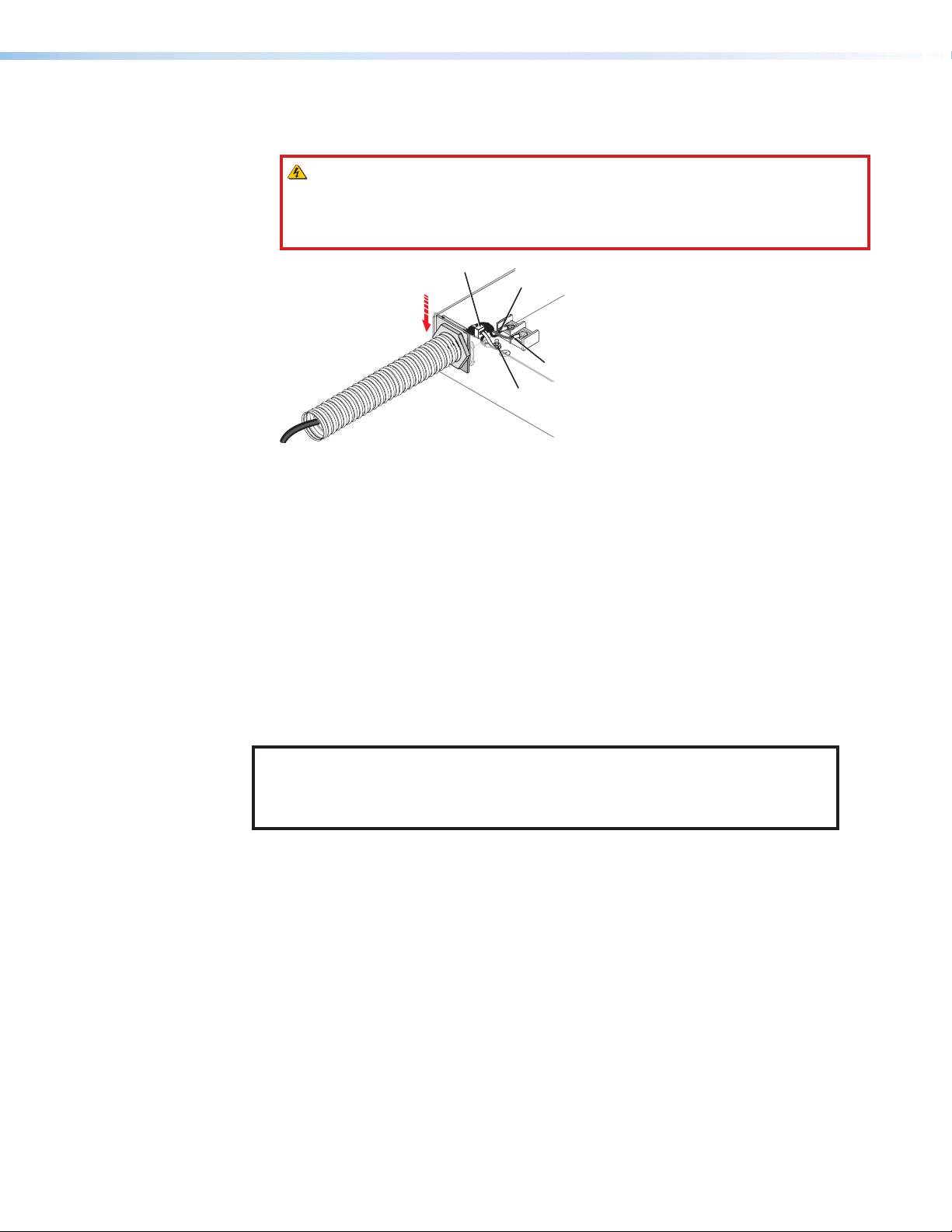
10. Connect the blue hot (line) and the brown neutral wires to the terminal block on the PCB
re
Tie Wrap
using the two screws removed back in step 3. Use the included zip tie wrap to secure
the two wires together close to the terminals.
WARNING: Ensure that you observe correct wire polarity. The following
illustration shows the location of the hot (line) and neutral terminals.
AVERTISSEMENT : Respecter la polarité correcte des câble. L’illustration suivante
indique l’emplacement des bornes de ligne et de neutre.
Blue Wire
Slide IEC
connector
plate and
conduit into
enclosue.
100-240V 1.3A
50-60Hz
L
N
Brown Wi
Grounding Nut
Figure 9. Install the Conduit Assembly
11. Connect the ground wire, as shown in the figure above, to the grounding stud located
on the bottom of the enclosure using the nut removed in step 4 on page10.
12. Replace the cover of the NetPA Ultra amplifier by reattaching the ten screws removed
back in step 2 on page9.
Installing the SAK AMP SF 10C Mounting Kit for NetPA U Amplifiers
The SAK AMP SF 10C mounting kit attaches an Extron Ultra Power Amplifier
(XPA U 2002 SB, NetPA U 2002 SB, or NetPA U 8001 SUB) to the back of an SF10CSUB.
This kit enables the amplifier to be mounted as close as possible to the subwoofer, thereby
allowing for the shortest possible speaker wiring.
Use the SAK AMP SF 10C kit to mount the Extron XPA U 2002 SB to the SF 10C as
follows:
NOTE: If the SF 10C SUB is being installed into a plenum airspace, the AC input
of the power amplifier must be replaced with the Flexible Conduit Adapter Kit.
Detailed instructions for the installation of this adapter kit can be found in the
user guide for the amplifier to be installed, at www.extron.com.
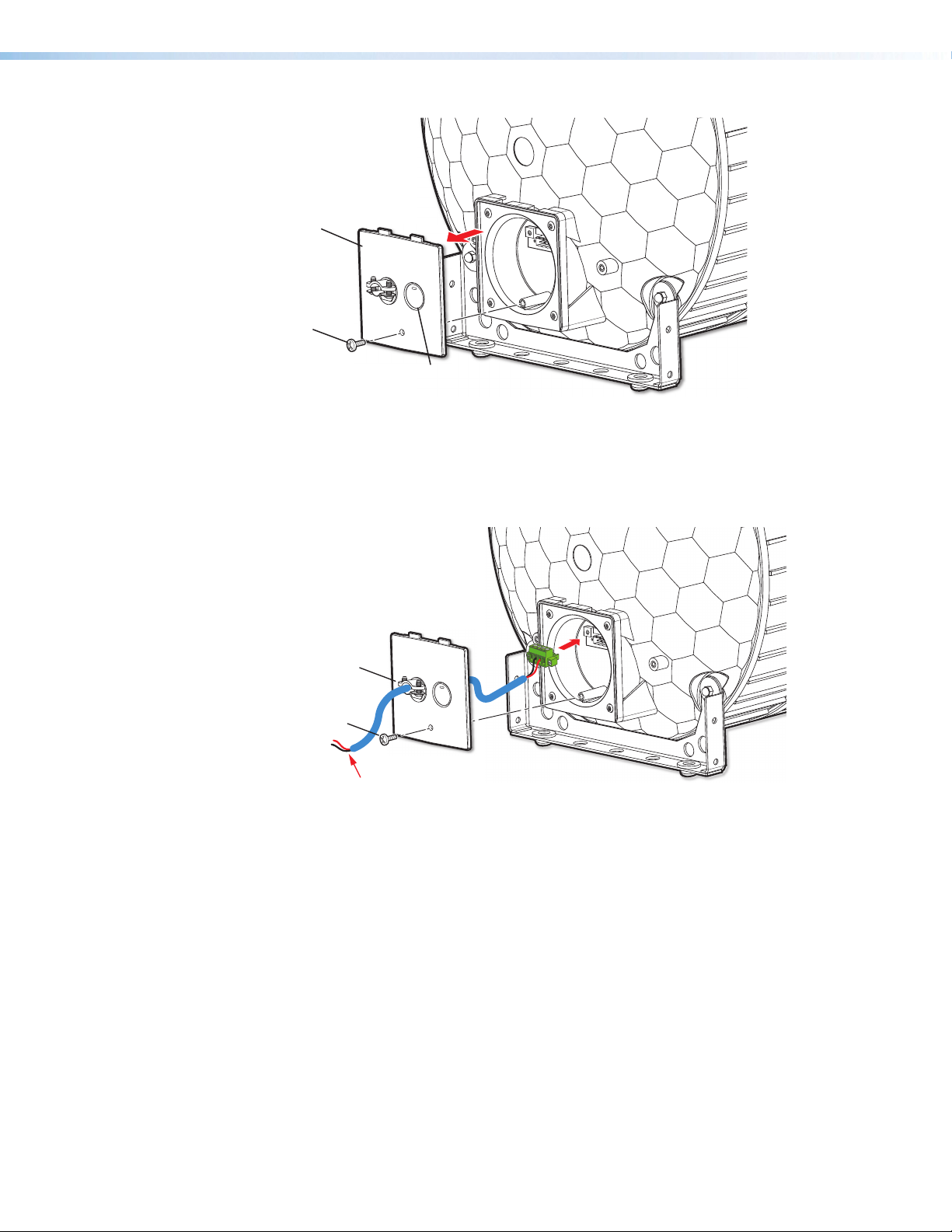
1. On the SF 10C, loosen the cable conduit access plate screw and remove the plate (see
figure10 on the next page).
NetPA U 2002 SB User Guide • Installation 11
Page 20
Cable Conduit
A
ccess Plate
2
A
Scr
111
Screw
Alternate
Knockout
Figure 10. Removing the Cable Conduit Access Plate
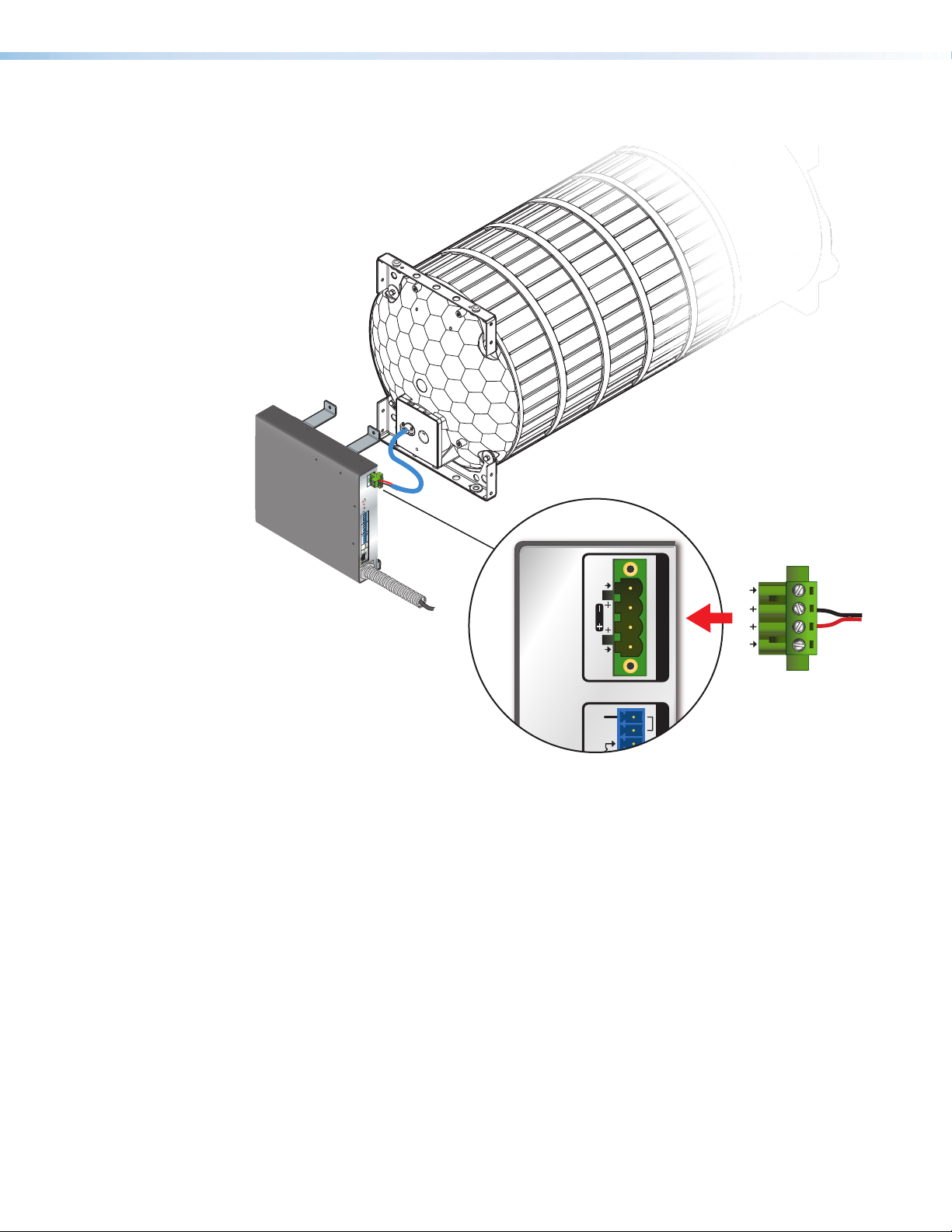
2. Remove the 4-pole captive screw connector that is attached to the speaker (see
figure11, 1).
3. Feed the unterminated end of the provided short cable through the back of the cable
clamp (see figure11, 1).
2
Cable
Clamp
111
2
ccess Plate
ew
Remove the jackets from the ends of the wires and
attach them to the captive-screw output connector
of the amplier.
Figure 11. Feeding the Cable through the Back of the Cable Clamp
4. Plug the 4-pole captive screw connector of the pre-terminated cable into the captive
screw connector on the speaker (2).
5. Reattach the cable conduit access plate to the speaker.
6. Tighten the cable clamp.
7. Attach the NetPA U 2002 SB amplifier to the SAK AMP SF 10C brackets using the
provided screws in the holes indicated in figure12 on the next page.
NetPA U 2002 SB User Guide • Installation 12
Page 21
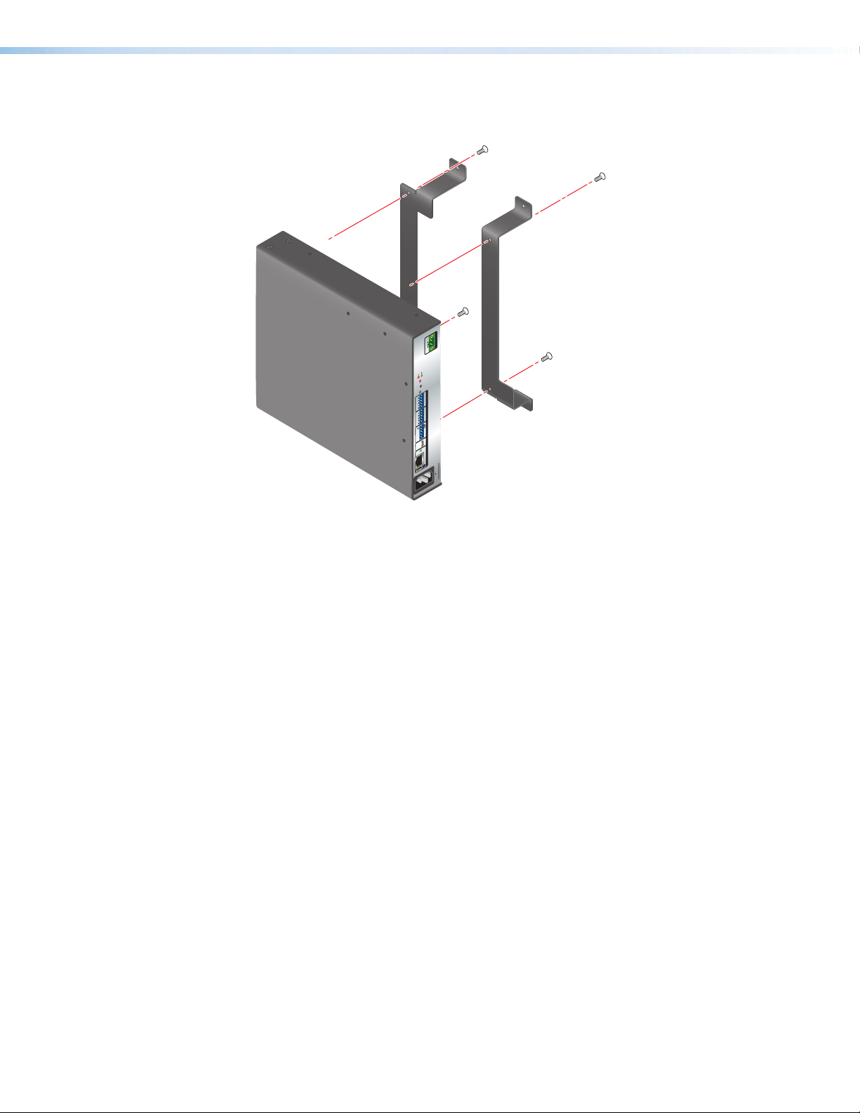
Attach the amplier with
screws (4 places).
8Ω/4Ω
OUTPUTS
OUTPUTS
8Ω/4Ω
CLASS 2 WIRING
SIGNAL
LIMITTER/PROTECT
TEMP
OVER
R
2
LINE OUT
1
2
LINE IN
1
G
REMOTE
STANDBY
G
RS-232
Rx
Tx
CONFIG
AT
--1.7A, 50-60 Hz
NetPA U 8001 SUB
100-240V
Figure 12. Attaching the Amplifier to the SAK AMP SF 10C Brackets
Attach the brackets (with the amplifier attached) to the screw holes on the end of the
SF 10C SUB speaker containing the cable conduit access plate, using the provided
screws (see figure10 on page12).
NetPA U 2002 SB User Guide • Installation 13
Page 22

Mounting Sc
(4 places)
LIMITT
ER
/PROTECT
SIGNAL
R
OVER
TEMP
1
2
1
2
RS-232
STANDBY
Tx
Rx
G
G
AT
CONFIG
LINE OUT
LINE IN
REMOTE
CLASS 2 WIRING
OUTPUTS
8Ω/4Ω
OUTPUTS
8Ω/4Ω
100-240V
--1.7A, 50-60 Hz
NetPA U 8001 SUB
rews
Figure 13. Attaching the Brackets and Amplifier to the SF 10C SUB
Subwoofer
8. Remove the jackets from the ends of the wires of the short cable that was attached to
the speaker in step 4 on page12.
9. Wire the green captive screw connector provided with your amplifier to the unterminated
ends of the cable wires (see figure14 on page15).
10. The NetPA U 2002 SB has 4-pole connectors.
• The red wire connects to the Channel 1 + pin.
• The black wire connects to the Channel 2 + pin.
NetPA U 2002 SB User Guide • Installation 14
Page 23
1
2
CLASS 2 WIRING
G
G
STANDBY
BR
8Ω/4Ω
OUTPUTS
OUTPUTS
8Ω/4Ω
CLASS 2 WIRING
ECT
PROT
TER/
SIGNAL
LIMIT
TEMP
OVER
R
2
LINE OUT
1
2
LINE IN
1
G
REMOTE
STANDBY
G
RS-232
Rx
Tx
CONFIG
AT
--1.7A, 50-60 Hz
NetPA U 8001 SUB
100-240V
XPA U 2002 SB
2
1
Figure 14. Connecting the Amplifier to the Subwoofer
NetPA U 2002 SB User Guide • Installation 15
Page 24
Operation
NetPA U 2002 SB
This section describes the operation of the NetPA U 2002 SB Amplifiers. Topics include:
• Front Panel Features
• Rear Panel Features
• Operation
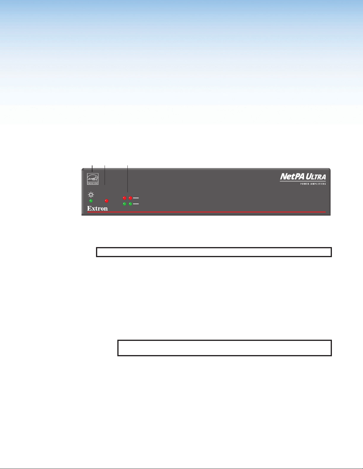
Front Panel Features
1
23
OVER
TEMP
Power/Standby Indicator
1
Figure 15. NetPA U 2002 SB Front Panel
NOTE: The front panels of all models in the NetPA Ultra Series function identically.
Power/Standby LED — A single LED that lights green when the unit is on and active,
1
and lights amber when:
• The unit is powering up and booting.
• The unit is in standby mode, which turns off all outputs from the amplifier although
• DC voltage is detected (see Troubleshooting on page105).
21
LIMITER/PROTECT
SIGNAL
Over Temp Indicator
2
the amplifier still receives power.
This LED flashes amber when an “Identify Device” request is sent to the unit via
Dante Controller, and the Link Indicator LED located on the rear panel blinks green.
Once the cycle has been completed, the LED returns to normal.
NOTE: Power indicator LED may light amber for a short time after the removal of AC
power. This is normal.
Channel Status LEDs
3
NetPA U 2002 SB
Over Temp Indicator — A single LED that lights red when the amplifier has exceeded
2
the maximum recommended operating temperature. The amplifier recovers once the
unit has sufficiently cooled down (see Troubleshooting on page105).
Channel Status LEDs — Two rows of two LEDs on the NetPA U 2002 SB that
3
represent amplifier channels.
• Limiter/Protect LED — This LED lights red when the channel is in protection
mode, which is triggered by any of the limiter protection circuits such as:
• When the channel is in an overload situation.
• When the output short circuits.
NetPA U 2002 SB USer Guide • Operation 16
Page 25
• Signal LED — This LED lights green when the output signal from a DSP channel
3
9
S
Balanced Input
Unbalanced Input
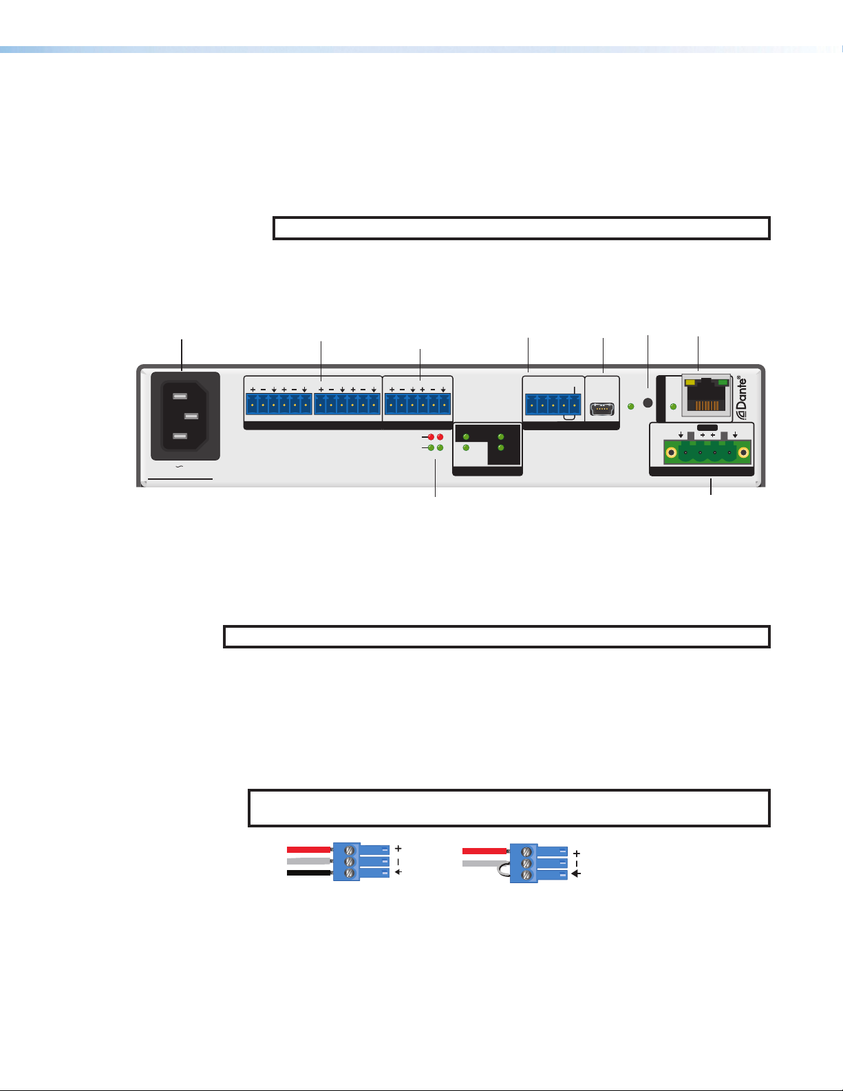
Rear Panel Features
1
• When digital clipping is detected on the output of the DSP going into the
amplifier channel.
• When the channel overheats.
that goes to an amplifier channel crosses the DSP signal detection threshold. The
threshold is -59dBFS.
NOTE: The LEDs are also located on the rear panel.
2
4
6
7
85
1 2 1 2
MIC/LINE INPUTS
100-240V 1.0A, 50-60Hz
NetPA U 2002 SB
IEC Power Receptacle
1
Mic/Line Inputs
2
Channel Status Indicators
3
3 4
LINE OUTPUTS
LIMITER/PROTECT
SIGNAL
Line Outputs
4
Remote Ports
5
USB Config Port
6
1 2
BRIDGED MONO
8Ω/16Ω
8Ω/4Ω
STEREO
OUTPUT MODE
70V
100V
Tx Rx
RS-232
STANDBY
G G
R
LINK
AT
CONFIGREMOTE
CLASS 2
Reset Button with Reset LED
7
AT Port with Link LED
8
Speaker Outputs
9
WIRING
+
BR
OUTPUTS
-
21
Figure 16. NetPA U 2002 SB Amplifier Rear Panel
NOTE: The rear panels of other NetPA Ultra Series amplifiers function identically.
IEC Power Receptacle — Connect a standard IEC AC power cord here for power
1
input
(100 VAC to 240 VAC, 50-60 Hz) to the internal, autoswitching power supply. This
connector may be replaced by the Flexible Conduit Adapter Kit (see Flexible Conduit
Adapter Kit Installation on page16).
Mic/Line Inputs — Connect up to four 3-pole 3.5 mm captive screw connectors to
2
input up to four balanced or unbalanced line level or microphone level signals.
NOTE: Inputs remain active during standby. Phantom power is not available on any of the
inputs.
Tip
Ring
leeve
Tip
Sleeve
Jumper
Figure 17. Captive Screw Connector Wiring
Channel Status Indicators — Two double-stacked LEDs. The top red LEDs are used
3
for Limiter/Protect status, and the bottom green LEDs are for signal status. The LEDs
function the same as the LEDs on the front panel.
NetPA U 2002 SB User Guide • Operation 17
Page 26

Line Outputs — (see figure16 on page17) Connect up to two 3-pole 3.5mm
Balanced Mono Output Unbalanced Mono Output
Do not tin
the wires!
Tip
Slee ve
Ring
Tip
Sleeve
4
captive screw connectors in order to output up to two balanced or unbalanced line level
output signals.
NOTE: The outputs do not remain active when the amplifier is in standby. For
applications where the line and Dante outputs may be used independently during
long periods of no amplifier activity, such as when the unit is being used as both
an amplifier and off/on-ramp to the Dante network, the auto-standby timer must
be disabled and the amplifier must not be forced into standby.
Figure 18. Captive Screw Connector Wiring
Remote Ports — (see figure16 on page17) Connect a 3.5 mm 3-pole captive
5
screw connector to the RS-232 port to remotely monitor and control the unit. Connect
a 3.5mm 2-pole captive screw connector to the standby port to remotely place the
amplifier in standby mode (see figure 16).
STANDBY mode is activated when the Standby pin is connected to the G pin.
Standby mode turns off all the outputs, although the amplifier still receives power. The
power LED on the front panel lights amber when the amplifier is in Standby mode.
The amplifier enters Standby mode when one of the following happens and are
prioritized, in order, as follows:
• Activation of the remote standby port (done by shorting the STANDBY pin to the
ground pin).
• Through the ‘PSAV’ SIS command, or through DSP Configurator (accessed via
Tools>Configure Standby Settings).
• After 25-minutes of inactivity.
NOTE: The inactivity timer can be disabled, and the standby pin and SIS Command
can continue to force the unit into standby mode (see Force standby on on
page93 in the SIS Command section to learn how to force standby mode).
Do not tin
the wires!
Figure 19. Captive Screw Connector Wiring
USB Config Port — (see figure16 on page17) Connect a mini USB type B
6
connector between this port and a computer for local configuration, and montoring the
amplifier.
Reset Button with Reset LED — (see figure16 on page17) Press this recessed
7
button to reset the amplifier. There are various reset modes. The reset LED indicates
which reset mode has been accessed.
• Mode 1 — Hold the Reset button while applying power to restore the unit
firmware back to the default factory firmware. This recovers a unit that has incorrect
code or updated firmware running. All user settings are maintained.
Rx
Tx
G
G
STANDBY
RS-232
Tx Rx
G
STANDBY
G
REMOTE
NetPA U 2002 SB User Guide • Operation 18
Page 27

• Mode 3 — To cause an absolute system reset of the Dante module back to factory
default conditions:
With power on, press and hold the reset button for about 3 seconds until the reset
LED blinks one time (once at 3 seconds), then release and within 1 second press
Reset momentarily (<1second).
Following this reset, the Dante module proceeds to its normal boot sequence. This
reset:
• Restores the IP Configuration to default settings.
• Clears all Dante audio channel routing.
• Sets the Dante device name and channel names to default.
• Mode 5 — With power on, press and hold the reset button for about 9 seconds
until the reset LED blinks three times (once at 3 seconds, again at 6 seconds, again
at 9 seconds), then release and press Reset momentarily ( < 1 second).
Mode 5 resets the device settings while preserving Dante specific settings such as
IP configuration, routing, device name, channel names, and sampling rate.
This reset:
a. Sets mix-points to unity gain (0 dBFS) and the following connections are made.
• AT input 1 is routed to amp output 1.
• AT input 2 is routed to amp output 2.
• AT input 1 is routed to line output 1.
• AT input 2 is routed to line output 2.
b. Unmutes amp outputs and sets to -24 dB.
c. Unmutes line and AT outputs and sets them to unity gain.
d. Sets trim blocks to unity gain.
e. Unmutes gain blocks and sets to unity gain.
f. Removes any inserted or active DSP.
g. Unmutes all line inputs and sets them to unity gain.
h. Clears all preset and group master memory.
i. Turns off status monitoring of unsolicited responses.
j. Enables standby timer.
k. Ensures unit will not be in standby mode.
l. The output mode will be set to 8Ω stereo.
The Reset LED flashes 3 times in quick succession during the reset.
AT Port with Link LED — (see figure16
8
on page17) Connect one RJ-45
connector to communicate with a Dante
network. The port uses the Dante protocol,
but can be configured for the AES 67
standard in Dante controller. It is one of the
ways the amplifier communicates with DSP
Configurator.
The Link LED is locked to the Dante
sync signal.
Pins:
12345678
Insert Twisted
Pair Wires
RJ-45
Connector
Crossover Cable
(for direct connection to a PC)
End 1 End 2
Pin Wire Color Pin Wire Color
1 white-orange 1 white-green
2 orange 2 green
3 white-green 3 white-orange
4 blue 4 blue
5 white-blue 5 white-blue
6 green6 orange
7 white-brown 7 white-brown
8 brown 8 brown
T568B T568A
A cable that is wired as TIA/EIA T568A at one
end and T568B at the other (Tx and Rx pairs
reversed) is a "crossover" cable.
NetPA U 2002 SB User Guide • Operation 19
Page 28

The LED has three states in normal operation:
• Blinking (1 Hz) Green: Unit generates network audio clock. The unit is the primary
clock.
• Lit Solid Green: Unit locked to network audio clock. The unit is following the
network audio clock.
• Off: Unit not locked to network audio clock.
Go to AT Port on page19 for more details on this port.
Speaker Outputs — (see figure16 on page17) Connect one 4-pin, 5 mm captive
9
screw connector for up to two channels of speaker output. Each port has a screw
flange to secure the plug to the connector. Observe the correct polarities for each
channel as shown below.
ATTENTION:
• You must use Class 2 wiring for this output to comply with UL requirements.
• Vous devez utiliser le câblage de classe 2 pour cette sortie an de vous conformer
aux exigences UL.
• Do not tie channel output pins to each other or to ground. Doing so will short out
the outputs, damage the amplifier, or both.
• Ne pas lier les sorties 1 et 2 des canaux entre elles ou à la terre. Les sorties
pourraient être court-circuitées et/ou l’amplificateur pourrait être endommagé.
• To avoid risk of damage to the amplier or the speakers, always check that low-
impedance speaker loads (4 Ω/8 Ω/16 Ω) and high-impedance speaker loads (70
V/100 V) are appropriately wired to the amplier for the desired mode.
• Pour éviter les risques de dommages à l’amplicateur ou aux haut-parleurs,
vériez toujours que les charges de haut-parleur à faible impédance (4 Ω/8 Ω/16 Ω)
et les charges de haut-parleurs à haute impédance (70 V/100 V) sont correctement
câblées à l’amplicateur pour le mode souhaité.
To wire the speaker output, do the following:
Each port has a screw flange to secure the plug to the connector. Follow the
instructions below to configure the rear panel for the NetPA U 2002 SB:
• For stereo modes, connect a 4-pin, 5 mm captive screw connector for two
channels of speaker outputs. The port has a screw flange to secure the plug to the
connector.
• For mono modes, connect the same 4-pin, 5 mm captive screw connector but wire
only the middle speaker output pins for a single channel of speaker output (see
figure20 on the next page to learn how to wire the speaker output).
NetPA U 2002 SB User Guide • Operation 20
Page 29
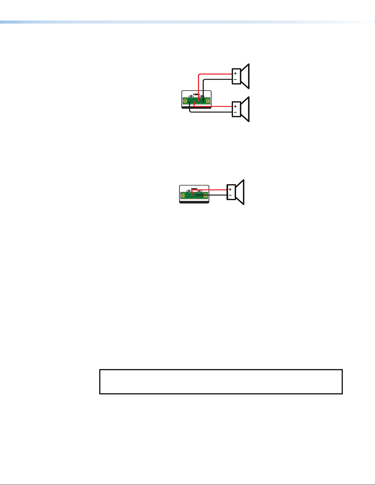
Stereo 8Ω or 4Ω Output Modes
Bridged Mono 8Ω/16Ω/70V/100V Modes
Stereo 8Ω or 4Ω
Speaker Loads
Wire output connector
to speaker loads as
shown to the right
1
2
CLASS 2 WIRING
OUTPUTS
BR
CH 2
CH 1
Mono 8Ω, 16Ω, 70V,
or 100V Speaker Loads
Wire output connector
to mono speaker load
as shown to the right
1
2
CLASS 2 WIRING
OUTPUTS
BR
CH 1
Operation
Default
Figure 20. Securing Speakers Wire with Captive Screws
The section below details some of the NetPA Ultra Series amplifiers features.
The following are the NetPA U 2002 SB amplifier defaults right out of the box:
• Amplifier output mode is set to stereo,
8ohms.
• All mix-points and trim blocks are set to
unity gain.
• All line outputs, AT outputs, gain blocks,
and line inputs are unmuted and set to
unity gain.
• Routing
AT Inputs are routed to their respective amp and line outputs (ex: AT Input 1 routed to
amp output 1 and line output 1.)
NOTE: The attenuation blocks of the amplifier outputs are set to -24 dB in order to
prevent an excessive amount of signal from being passed to the speaker before the
amplifier can be properly configured.
• Standby timer is enabled and unit is not
in standby.
• Unsolicited response status monitoring
is disabled.
• Attenuation blocks are unmuted and
set to -24 dB for amplified outputs, 0
dB for line and AT outputs.
NetPA U 2002 SB User Guide • Operation 21
Page 30

AT Port
The NetPA U 2002 SB supports 2 AT inputs and 2 AT outputs (these are not shared with the
analog line outputs). Audio coming in from the mic/line inputs can be placed onto the Dante
network, and the AT outputs can be received by any other device as long as it’s using the
Dante protocol. The port supports bi-directional channels of 24 bit/48 kHz digital audio.
NOTE: The AT port can be set to 44.1 kHz, 48 kHz, 88.2 kHz, or 96 kHz, however the
signal going through the DSP is converted to and processed at 48 kHz.
The AT port allows latency to be set per device at 1.0 ms, 2.0 ms, or 5.0 ms.
Dante Controller provides control and configuration to the entries listed below. However,
Dante Controller is not limited to the entries.
• Dante channel routing
• Dante channel naming
• Dante reboot
• Device naming
• Setting network master clock
• Get network and device Dante status
• Set DHCP mode and device IP address
NOTE: For applications where the line and Dante outputs may be used independently during long
periods of no amplifier activity, such as when the unit is being used as both an amplifier and off/
on-ramp to the Dante network, the auto-standby timer must be disabled and the amp must not
be forced into Standby mode.
• Setting sample rate to one of the
following frequencies:
• 44.1 kHz
• 48 kHz
• 88.2 kHz
• 96 kHz
Standby Modes
The amplifier may be placed into 3 standby modes through SIS, DSP Configurator or a
control system. The unit may also be forced into standby through the rear panel contact
closure.
To change the Standby settings via DSP Configurator:
Navigate to the Tools menu and select Configure Standby Settings, then make
your selection to change the settings.
Standby Modes
• Disable Auto-Standby Timer = Mode 0
• Enable Auto-Standby Timer = Mode 1
• Force Standby Mode = Mode 2
NetPA U 2002 SB User Guide • Operation 22
Page 31

Figure 21. Configuring Standby Settings
See the SIS command, Standby on page93 for the commands to send to the amplifier.
Standby Selection (via SIS or Control System):
Mode 0: When the amplifier is in Standby Mode 0, the Auto-Standby Timer is disabled
and the amplifier does NOT automatically enter standby mode when no active signal is
present on any amp channel for 25 minutes.
Mode 1: When the amplifier is in Standby Mode 1 (default), the Auto-Standby Timer is
enabled. The amplifier remains active while there is an active signal on any amp channel.
The amplifier enters standby mode if no active signal is present on any amp channel for 25
minutes. It returns to active upon detection of signal on any amp channel. When the SIS
command is sent, the timer resets and the amplifier goes into power save state 1.
Mode 2: When the amplifier is forced into Standby Mode 2 via SIS, DSP Configurator, or
a control system, the unit remains in standby until the amplifier is placed into Standby Mode
0 or 1 the same way, regardless of signal presence.
Mode 3 (not accessible via DSP Configurator or SIS): This mode occurs when the
amplifier begins in Mode 1 and there is no active signal present on any amp channel for
25 minutes. In this mode the amplifier is in standby and can be taken out of standby via an
active signal on any amp channel, DSP Configurator, or SIS.
Mode 4 (not accessible via DSP Configurator or SIS): When the amplifier is forced
into standby via the STANDBY port (contact closure), it remains in this state until the contact
is opened. Once opened, the amplifier returns to its last known standby state. This function
overrides all other standby conditions.
NOTE:
• In Standby mode, the line and Dante outputs are muted.
• It is important to note that the auto-standby function relies on active signals that
are routed to the amplified outputs. Signals that are routed only to the line or
Dante outputs, but not the amplifier outputs, do not prevent the unit from going
into auto-standby due to inactivity.
• For applications where the line and Dante outputs may be used independently
during long periods of no amplifier activity, such as when the unit is being used as
both an amplifier and off/on-ramp to the Dante network, the auto-standby timer
must be disabled, and the amplifier must not be forced into Standby mode.
NetPA U 2002 SB User Guide • Operation 23
Page 32
Monitoring
X! = xxxx
Signal Presence
Overload
Digital Clipping
General
There are two methods to monitor the amplifier, querying and unsolicited responses. Either
method or a combination of the two can be employed.
NOTES:
• All status flags reset upon power cycle. Status flags can also be reset via SIS (see
Resets on page97).
• See Status on page98 of the SIS section and Troubleshooting on
page105 of the guide for detailed descriptions of each status.
Querying:
1. See Status on page98 for the commands to query.
2. Each status command is capable of being queried.
3. Query commands can be used when polling with a control system.
4. All statuses can be queried, even when unsolicited responses are enabled.
Unsolicited responses:
NOTE: Unsolicited responses are turned off by default to reduce unecessary network
traffic, and must be turned on if needed.
1. Set the unit to verbose mode 2 or 3.
2. Use the NTFY command (see Status on page98) to configure.
• EMX!*X@NTFY}
•
Where x = 1 (on) or 0 (off [Default]).
Determines which unsolicited responses get turned on.
NOTE: Some responses may not be desired or may report too frequently,
requiring them to be disabled.
• X@ = x
Where x = 0 (Default) - 3.
0. All (Default)
1. Dante Port
2. RS-232
3. USB
• This variable specifies which port to direct the responses.
• This is useful when you need to keep traffic to a minimum on a particular port or
ports.
NetPA U 2002 SB User Guide • Operation 24
Page 33

• When listening over the Dante port, a DMP Plus Series device is needed to facilitate
communication between the amplifier and control system.
Amplifier must be in verbose 3.
Connection to DMP/XMP must be in verbose 3.
The connection must be maintained.
The following command is used to configure the DMP to listen to the amplifier.
ECX!*X@EXPR}
X!: Dante device name
X@: 0 = off, 1 = on
NOTE: For additional information about Dante format, please see either the
DMP Plus or XMP 240 User Guides available at www.extron.com.
NetPA U 2002 SB User Guide • Operation 25
Page 34
DSP Configurator Software
Extron DSP Configurator Software is the main user interface for control and management
of the Extron NetPA U 2002 SB power amplifier and all of its audio functions, including
amplifier output mode selection, mixing, gain, dynamics, filtering, delay, microphone
ducking, and monitoring. This section describes the Extron DSP Configurator software and
covers the following topics:
• Downloading and Installing DSP Configurator • Mic/Line Inputs Processing
• Accessing the DSP Configurator Help File • DSP Configurator Outputs
• DSP Configurator Main Workspace • Amplifier Outputs
• Menu Bar • Monitoring
• DSP Configurator Inputs
Downloading and Installing DSP Configurator
1. On www.extron.com, hover over the Download tab at the top of the page.
2. From the Feature Software list, select DSP Configurator Software.
3. From the DSP Configurator Software product page, click the blue Download
button.
4. Select Run to run the DSP Configurator installer. Select Save to save the install file to
run at a later time.
5. To run DSP Configurator from the default install location, click
Start>Programs>Extron>DSP Configurator>DSP Configurator
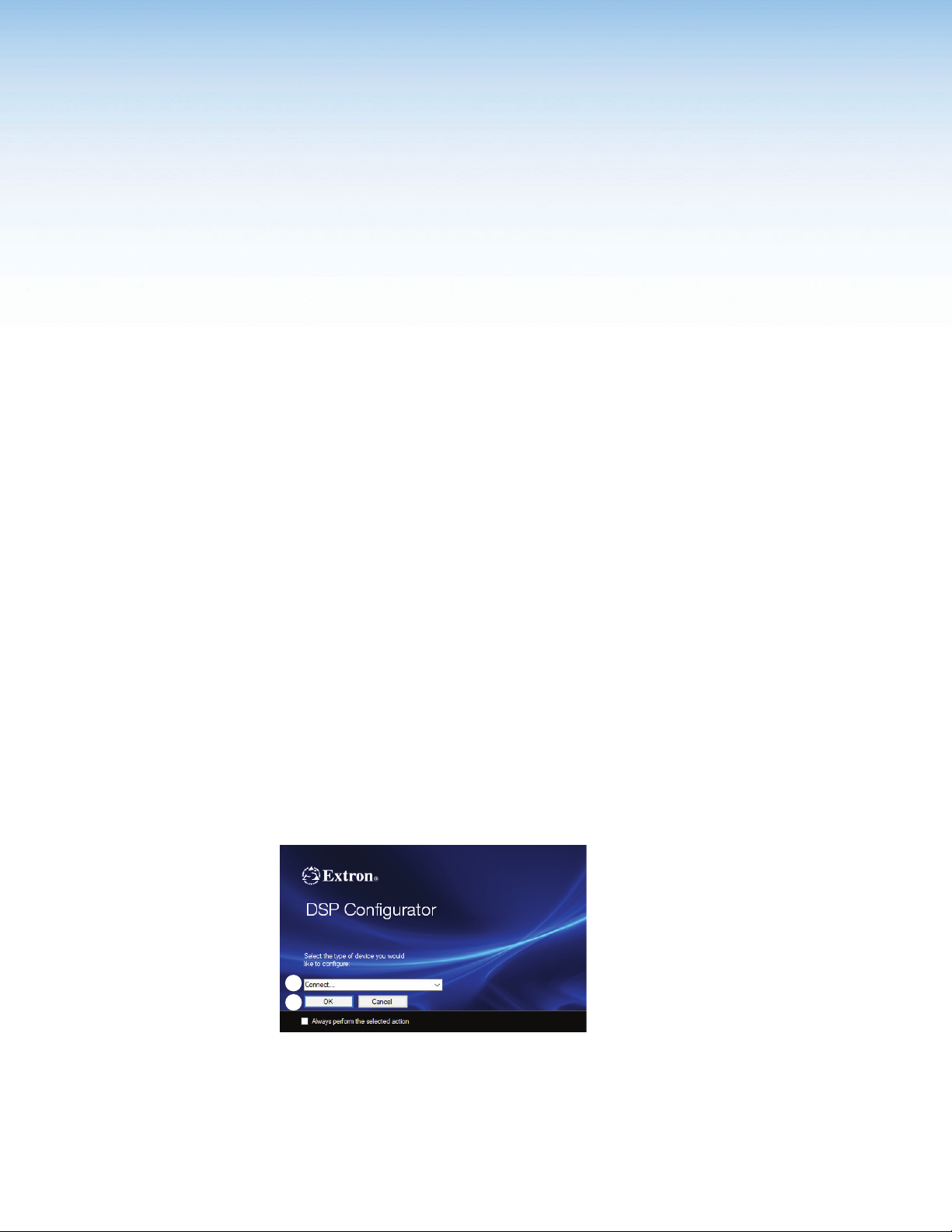
6. From the DSP Configurator splash screen drop-down menu (figure 19, 1), select the
NetPA Ultra Series model that is connected to the host PC and click OK (2).
1
2
Figure 22. DSP Configurator Splash Screen
NetPA U 2002 SB User Guide • DSP Configurator Software 26
Page 35
Accessing the DSP Configurator Help File
111
2
3
DSP Configurator comes loaded with a context-sensitive help file, which can be accessed
by clicking the Help icon (see the icon to the right) in the top right corner. The Help
icon is always in the top right corner of any dialog box in DSP Configurator. There are other
options to accessing the help file: click Help>Contents in the menu bar at the top of the
main workspace, or press F1.
The help file contains detailed procedures and further instructions on all of the DSP
Configurator features.
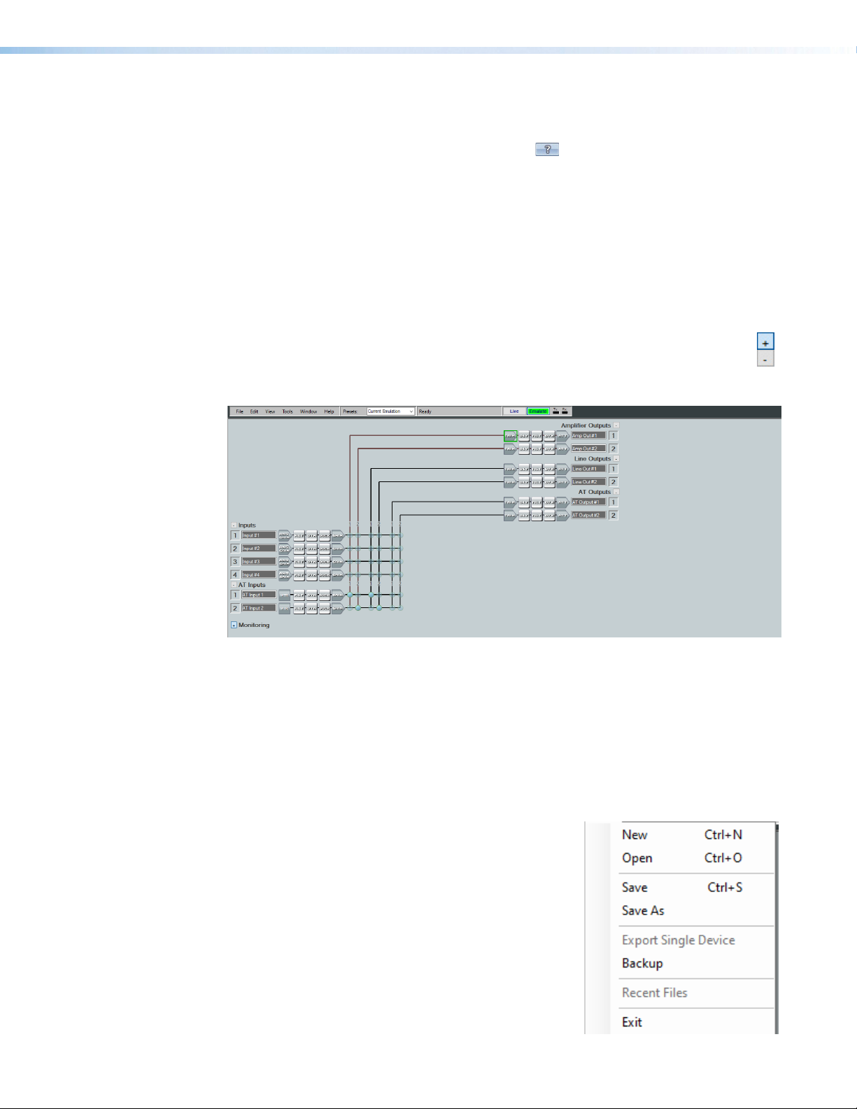
DSP Configurator Main Workspace
The DSP Configurator main workspace can be divided into four main sections (see
figure 20). Each section contains various functions to configure the NetPA U 2002 SB
amplifier. Use the expand and collapse button, (as seen to the right) next to the input
and output group names to show or hide the groups and their corresponding mix
matrices.If necessary, scroll through the window by using the mouse wheel or the
scroll bar at the right side of the DSP Configurator main workspace.
444
2
2
3
3
Menu Bar
1
Figure 23. DSP Configurator Main Workspace
DSP
2
Configurator
Inputs
3
Mix-Points
DSP
4
Configurator
Outputs
Menu Bar
File
New — Opens a new configuration file. This is only
1
available in Emulate mode (see Emulate Mode on
page24). If the current configuration has not been
saved, the Save dialog box opens and asks to save
the current configuration before a new one is
opened. Click Yes to save the current configuration
or No to delete it and open a new configuration.
Click Cancel to return to the current configuration.
Open — Opens an existing configuration or template
2
file. When selected, the Browse dialog box opens
to search for a saved configuration or template file.
Double-click the configuration or template file to load it.
1
2
3
4
5
6
7
8
NetPA U 2002 SB User Guide • DSP Configurator Software 27
Page 36
NOTE: Configuration files have a .EDC file extension and template files have a
.EDCT file extension.
Save — (see File on page27) Saves the current configuration to a configuration file.
3
If this is the first time the configuration is being saved, the Save Configuration
As... dialog box opens. Enter a name and save location for the configuration file.
Save As — (see File on page27) Saves the current configuration file under a new
4
name and location, or as a template file. When selected, the Save Configuration
As... dialog box opens.
Export Single Device— (see File on page27) Saves the selected device in
5
Device Manager as a configuration file. This function is used to save an individual
device when there are multiple devices listed in the Device Manager (see Device
Manager on page67).
Backup— (see File on page27) Recalls and transfers all partial presets of a NetPA
6
Ultra amplifier to the configuration file or template file within DSP Configurator.
Recent Files — (see File on page27) Lists the five most recently opened
7
configuration files. These files can be selected and loaded into DSP Configurator.
Exit — (see File on page27) Closes DSP Configurator. If the current configuration
8
has not been saved, the Save dialog box opens and prompts the user to save the
current configuration before closing. Click Yes to save the file. Click No to exit the
application without saving. Click Cancel to return to the main workspace and keep
the application running.
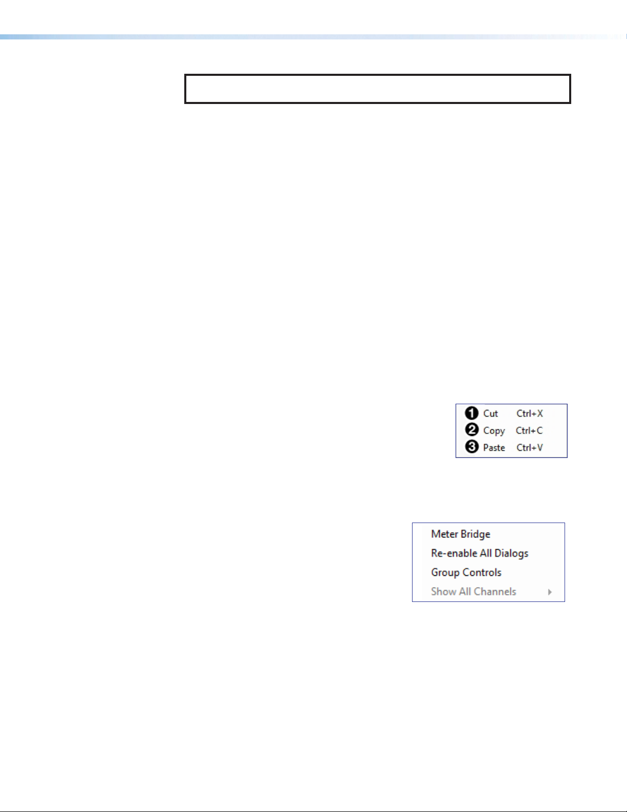
Edit
Cut — Removes the configuration of selected elements in
1
the workspace to be pasted to other elements.
Copy — Copies the configuration of selected elements in
2
the workspace to be pasted to other elements.
Paste — Applies the cut or copied configuration of
3
elements to the selected elements in the workspace.
View
Meter Bridge — Opens a meter bridge to view
1
input and output activity. The meter
bridge is a floating window that allows the
use of DSP Configurator while simultaneously
monitoring input and output activity.
Re-enable All Dialogs — This option re-enables
2
all dialog boxes to no longer appear based on
user selection (certain dialog boxes appear as user-defeatable by selecting a checkbox
that reads Do Not Show This Dialog Again).
Group Controls — Opens the Group Controls dialog box to access existing group
3
controls and add new groups.
Show All Channels — Individual channels can be hidden by user selection. This
4
provides options for the user to select which input and output groups are visible in the
main workspace.
1
2
3
4
NetPA U 2002 SB User Guide • DSP Configurator Software 28
Page 37
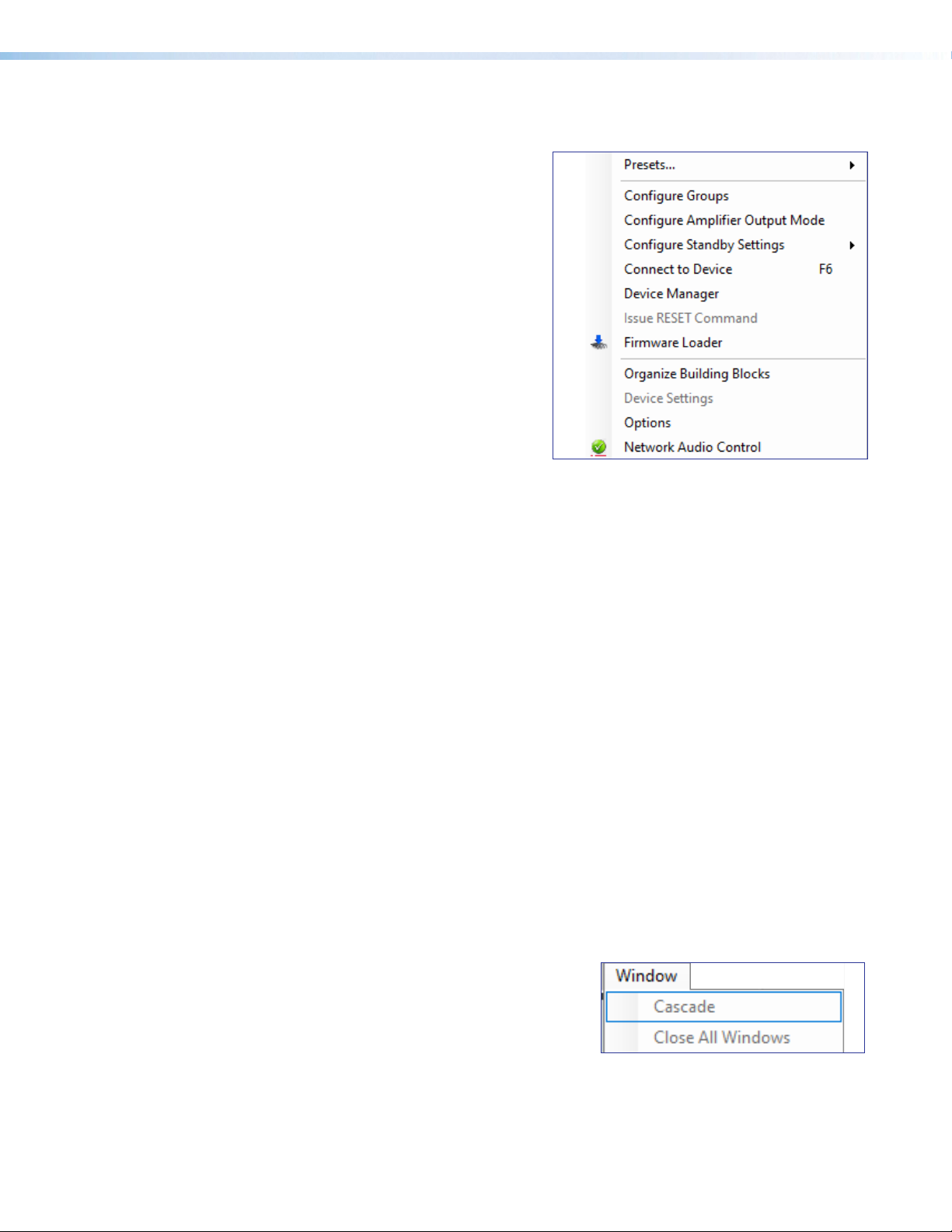
Tools
Presets — Contains a submenu to
1
mark and clear elements in the main
workspace as well as an option to
save marked elements to a preset (see
Presets on page63).
Configure Groups — Opens the
2
Configure Groups dialog box to create,
edit, and delete Gain and Mute groups
(see Groups on page65).
Configure Amplifier Output Mode —
3
Opens the Configure Amplifier Output
Mode dialog box (see Configuring the
Output Mode on page55).
Configure Standby Settings —
4
Opens a submenu to disable or enable
the auto-standby timer or force standby
mode.
Connect/Disconnect from Device — When in Emulate mode, this reads as
5
Connect to Device and opens the Connect to Device dialog box (see
Connect/Disconnect from Device on page69). When in Live mode, this reads
Disconnect from Device and returns software to Emulate mode.
1
2
3
4
5
6
7
8
9
¢
£
¤
Device Manager — Opens the Device Manager dialog box (see Device Manager
6
on page67).
Issue RESET Command — Clears the amplifier of all processors and other
7
configuration settings. This command does not reset general settings such as IP
address (see Hardware Reset Modes on page89).
Firmware Loader — Opens the Firmware Loader application, if it is installed (see
8
Firmware Loader on page70). Visit www.extron.com to download the software.
Organize Building Blocks — Opens the Organize Building Blocks dialog box
9
(see Organize Building Blocks on page71).
Device Settings — Opens the Device Settings dialog box to edit date and time,
¢
IP address, DHCP status, and other settings (see Device Settings on page72).
Options — Opens the Options dialog box to configure DSP Configurator
£
appearance, default settings, DSP value defaults, and so on (see Options on
page74).
Network Audio Control — Opens the Dante Controller application by Audinate
¤
for routing audio over a Dante network (see Dante Controller on page75).
Window
Cascade — Organizes windows by
1
cascading them in the same order they were
opened.
Close All Windows — Closes all open
2
windows, leaving only the main workspace
visible. When all windows are closed,
parameter changes are saved before the
window is closed.
1
2
NetPA U 2002 SB User Guide • DSP Configurator Software 29
Page 38
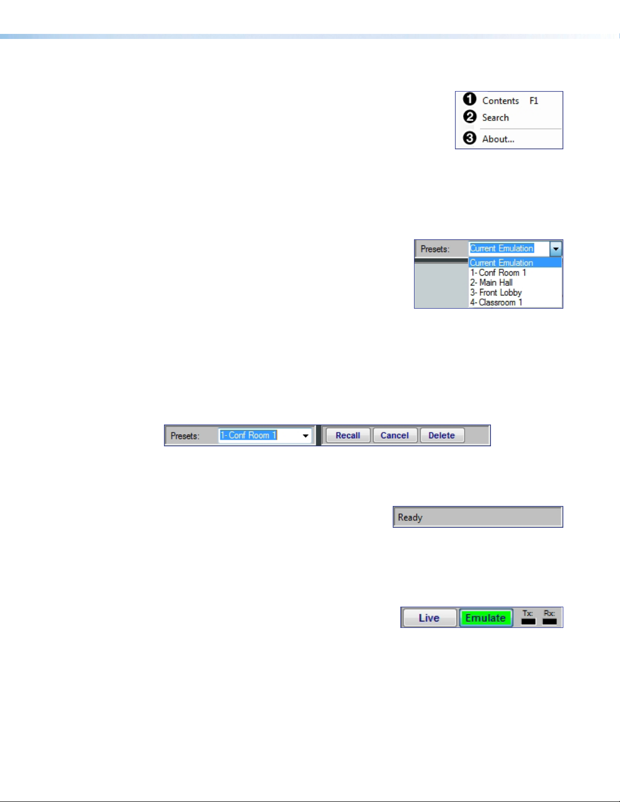
Help
Contents — Opens the DSP Configurator Help File
1
where detailed information about DSP Configurator can
be found.
Search — Opens the DSP Configurator Help File with the
2
Search field in focus.
About — Opens a window displaying software version number, copyright information,
3
and part number for the installed copy of DSP Configurator. Click the Details button for
a list of advanced details, such as build number.
Presets Drop-Down
The Presets drop-down list (see the image at right)
allows the user to view and apply presets saved in the
current configuration file or on a device connected in
Live mode. Presets with an asterisk next to them are
on the amplifier, but not in the current configuration file.
Run a preset to load it into the configuration file.
Alternatively, perform a backup to run all presets and
load them into the current configuration file (see File on page27).
After selecting a preset from the list, choose one of the following actions from the
DSPConfigurator status panel:
• Recall — Recalls the selected preset and applies settings to the main workspace.
• Cancel — Cancels the preset recall and returns to the main workspace with the current
emulation or state intact.
• Delete — Deletes the selected preset from the configuration.
Figure 24. Preset and Action Selection
DSP Configurator Status Panel
This panel displays the current status of
DSP Configurator and shows when data is being
pushed to or pulled from the device. When the
software is ready to perform actions, the panel
reads Ready (see the image at right).
Live and Emulate Panel
The Live and Emulate buttons allow users to
switch between Live and Emulate mode and
displays transmit activity (Tx) and receive activity
(Rx) when in Live mode.
NetPA U 2002 SB User Guide • DSP Configurator Software 30
Page 39
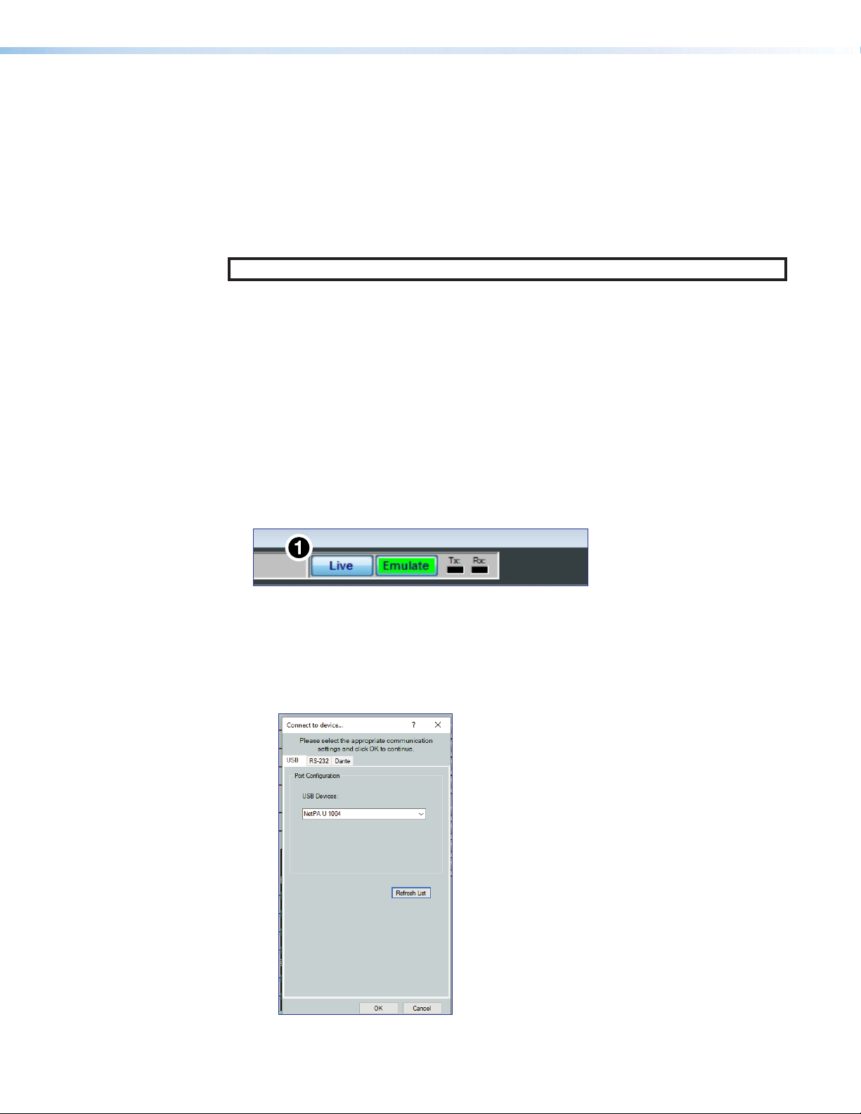
Emulate Mode
While in Emulate mode, DSP Configurator is functioning in an “offline” state. Changes made
to the configuration file are not applied to a device.
In Emulate mode, the user can create and configure the software as though a device was
connected, except for any actions that require direct connection to the device or information
that is stored only on the device. Once configuration is complete, the user can switch to
Live mode and apply the configuration to the device or save the configuration file to be
loaded onto one or multiple devices at a later time.
Creating configuration files in Emulate mode saves time by not requiring a device to be
connected or present in order for the bulk of DSP configuration to be completed.
NOTE: Not all menu options or actions are available in Emulate mode.
Live Mode
Enter Live mode to connect to the NetPA U 2002 SB amplifier and push or pull
configurations between the device and host PC. In Live mode, changes made in DSP
Configurator are directly applied to the NetPA Ultra Series amplifier. Additionally, presets can
be created and stored on the device.
When entering Live mode, the user is prompted with the Connect to device dialog box.
Connect to a NetPA U 2002 SB Amplifier in Live Mode
1. Click the Live button in the menu bar of DSP Configurator (see figure 25, 1).
Alternatively, select Tools > Connect to Device or press <F6> on the keyboard. The
Connect to device... dialog box opens (see figure25).
Figure 25. Live Button
2. Connect to the amplifier.
• To connect via USB:
Click the USB tab in the dialog box. Select the device from the USB Devices
drop-down list.
Figure 26. Connect to device... USB Dialog Box
NetPA U 2002 SB User Guide • DSP Configurator Software 31
Page 40
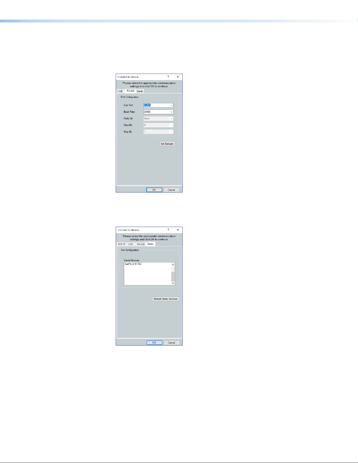
• To connect via RS-232:
Click the RS-232 tab in the dialog box. Select the unit connected via RS-232 from
the Com Port drop-down list, and then select the correct Baud Rate, Parity
Bit, Data Bit, and Stop Bit.
Figure 27. Connect to device... RS-232 Dialog Box
• To connect via Dante:
Click the Dante tab in the dialog box. Select the device from the list, then click OK.
Figure 28. Connect to device... Dante Dialog Box
• When a connection with a device is established, the Synchronize with Device
dialog box opens (see figure29, on the next page).
NetPA U 2002 SB User Guide • DSP Configurator Software 32
Page 41
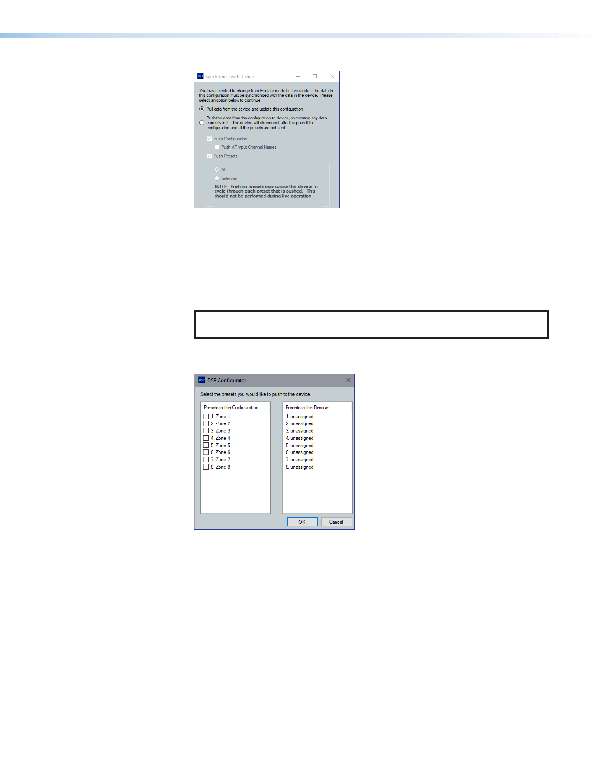
Figure 29. Synchronize with Device Dialog Box
Pull — Pulls the configuration file and preset configurations from the device
1
and displays it in the DSP Configurator main workspace.
Push — Pushes the configuration file and preset configurations open in DSP
2
Configurator to the connected NetPA U 2002 SB. The check boxes indicate
what is pushed when OK is selected. Pushing a selected item overwrites that
item on the device.
NOTE: If only pushing selected presets, the preset selection dialog box opens
after clicking OK, allowing you to select which preset to push to the device.
• If only pushing selected presets, mark them from the dialog box shown in figure30
on the next page.
Figure 30. Preset Selection Dialog Box
Once a push or pull is completed, the current state of the connected unit is
displayed in the DSP Configurator status panel and the device is ready for further
configuration.
Exit Live Mode and Enter Emulate Mode
1. Click the Emulate button in the DSP Configurator menu bar (see figure31, 1 , on the
next page). Alternatively, select Tools > Disconnect from Device or press <F6> on
the keyboard.
NetPA U 2002 SB User Guide • DSP Configurator Software 33
Page 42

Figure 31. Emulate Button
2. Click OK to confirm.
DSP Configurator Inputs
All available inputs are listed vertically along the left side of the DSP Configurator main
workspace. The input groups can be expanded or collapsed by clicking the (expand) or
(collapse) buttons next to the input group names.
There are two types of inputs available:
• Mic/Line Inputs • AT Inputs
Mic/Line Inputs
The four mic/line input channels in the NetPA Ultra Series amplifier are shown in
DSPConfigurator under the Inputs panel (see figure 32, below).
Figure 32. Inputs Panel
Inputs 1 - 4 can receive mic level or line level signals.
Naming an Input Channel
1. Click the input name field.
2. Highlight or delete the text and enter a new name.
3. Press <Enter> or navigate away from the field to confirm
and apply the new input name. Press <Down Arrow> key
to navigate to and highlight the next name field.
NOTE: Follow the same procedure to edit an input name.
Input Building Blocks
Extron building blocks are a quick configuration tool that can significantly reduce
configuration time. An input building block is a collection of processor and gain settings for
an input processing chain. These building blocks have been designed by Extron based on
extensive use and testing with each intended application or specific device.
NetPA U 2002 SB User Guide • DSP Configurator Software 34
Page 43

Figure 33. Accessing Input Building Blocks
Click the input number to open the Building Blocks dialog box.
Building Block Folders
1
General Building Blocks
2
Add a Building Block Button
3
Delete a Building Block Button
4
New Folder Button
5
Building Blocks Help Button
6
Figure 34. Input Building Blocks Dialog Box
Building Block Folders — These folders group
1
input types together, such as table or handheld mics,
for easy access (see the image on the right).
General Building Blocks — These building blocks
2
provide quick setup for input sources. General
building blocks provide a useful starting
point for devices in the same product category as
the name of the building block, such as handheld
microphones, line level sources, and so on.
Add a Building Block Button — Creates a custom
3
building block from the current gain and processor
settings on the selected channel.
When this button is clicked, the Add a Building Block dialog box opens. Name the
new custom building block and choose a folder to
save the
block to, or create a new folder (see the image on
the right).
Delete a Building Block Button —
4
Deletes the currently selected building block or
building block folder. If default building blocks are deleted, they can be restored from the
Organize Building Blocks dialog box. Custom building blocks can be saved to a
file from the same dialog box (see Organize Building Blocks on page71).
New Folder Button — Creates a new folder or sub-folder in the Building Blocks
5
dialog box.
Building Blocks Help Button — Opens the Building Blocks topic of the
6
DSPConfiguratorHelp File. This topic contains more information on the different types
of building blocks for inputs and outputs.
NetPA U 2002 SB User Guide • DSP Configurator Software 35
Page 44

5
Mic/Line Inputs Processing
The mic/line input processing chain in DSP Configurator is visually represented by a string
of blocks(see figure35). Each block contains a specific processor or type of processor. For
example, the Input Gain block contains a fader to boost or attenuate incoming signal, the
Filter block contains several types of filters, and so on. Inputs 1 - 4 contain the following
signal chain:
• Input Gain Block • Input Ducking Block
• Input Filter Block • Input Pre-Mixer Gain Block
• Input Dynamics Blocks
Figure 35. Input Processing Chain
Input Gain Block
Double-click the Input Gain block (as seen to the right) to open the Input Gain
dialog box.
The Input Gain dialog box provides controls to configure
the input gain stage of the input processing path.
Input Name — This name changes to match the default
1
or user defined input name.
Gain Fader — Provides up to 60 dB of gain or 18dB
2
of attenuation. Click the fader once and press the
<Up Arrow> or <Down Arrow> keys to adjust the fader
up or down in 1 dB steps. Press the <Page Up> or
<Page Down> keys to adjust the fader up or down in
10 dB steps.
dBFS Meter — This meter displays the input signal level
3
in dBFS, ranging from -60dBFS to 0dBFS. Once the
signal reaches or passes -1dBFS (default) or the clip
threshold defined in the Options dialog box (see
Options on page33), the clip box located at the top of
the meter lights red.
dBFS Numeric Readout — This read-only text box
4
displays the numerical value of the input signal level in
dBFS.
Input Gain Text Field — This text field allows the user to
5
enter a gain or attenuation value in 0.1 dB steps.
Polarity Toggle Button — Inverts the signal polarity of
6
the selected input. When the button displays the black + symbol on a gray field ( ), the
polarity is normal. When the button displays the black - symbol on a yellow field ( ), the
polarity is inverted.
Mute Button — Mutes signal at the input stage, preventing it from going any further in
7
the signal processing chain.
OK Button — Confirms changes and closes the Input Gain dialog box.
8
Cancel Button — Reverts any changes made to the contained parameters back to
9
their states when the current instance of the Input Gain dialog box was opened and
closes the dialog box.
Input Gain Help Button — Opens the Mic/Line Input Gain topic in the
¢
DSPConfiguratorHelp file for further assistance in configuring input gain.
1
2
7
8
¢
3
4
6
9
NetPA U 2002 SB User Guide • DSP Configurator Software 36
Page 45

Input Filter Block
1
2
3
4
5
6
7
Double-click the Filter block to open the filter drop-down list. Select one of the six
available filters to insert into the block.
Figure 36. Filter Block Drop-Down Menu
Alternatively, right-click the Filter block and select Insert, then select a filter to insert it
into the block.
Figure 37. Insert Filter Drop-Down Menu
Once an initial filter is selected, the Filter block changes to display
the type of filter applied. For example, if High Pass Filter is
selected, the Filter block would display HIGH PASS instead of
FILT. If multiple filters are applied, the Filter block displays FILT
over a dark green field.
Once a filter is applied to the Filter block, double-click the block to open the Filter
dialog box.
Filter Channel
1
Name
Filter Graph
2
Filter List
3
Set Deafults
4
Button
OK Button
5
Cancel Button
6
Filters Help Button
7
Figure 38. Filter Dialog Box
Filter Channel Name — This name changes to match the default or user defined input
1
name.
NetPA U 2002 SB User Guide • DSP Configurator Software 37
Page 46

Filter Graph — (see figure38 on page37) Graphically displays the applied filter
2
curve and provides handles for adjusting filter parameters. Numbers along the top of the
graph represent the filter curve of the corresponding slot in the filter list below the graph.
The number appears over the center frequency of the filter.
If a filter is active (unbypassed), it appears as a solid red curve. If a filter is bypassed, it
appears as a broken orange curve (such as the bass filter in slot 2).
NOTE: All filters are bypassed by default.
Filter List — (see figure38 on page37) Provides filter drop-down lists for all 5
3
available filter slots. Frequency, Slope, Boost/Cut, Q, and Bypass controls are also
available in this list.
Available filters include:
• High-pass Butterworth • High-pass Linkwitz-Riley • Parametric
• Low-pass Butterworth • Low-pass Linkwitz-Riley
• Bass • Treble
NOTE: See the DSP Configurator Help File for more information on each of the
filters. Click the Filters Help button to open the help file topic discussing
filters.
Set Defaults Button — (see figure38 on page37) Resets all filter parameters of all
4
filters in the filter list to their default values.
To reset a single filter to default parameters, right-click the
filter number on the left side of the Filter dialog box, and
select Set to Default (see the image on the right).
OK Button — (see figure38 on page37) Confirms
5
changes made to the contained parameters and closes the
Filter dialog box.
Cancel Button — (see figure38 on page37) Reverts any changes made to the
6
contained parameters back to their states when the current instance of the Filter
dialog box was opened and closes the dialog box.
Filters Help Button — (see figure38 on page37) Opens the About Filters
7
topic in the DSPConfiguratorHelp File. This help file topic discusses each filter type in
greater detail.
Input Dynamics Blocks
Double-click the Dynamics block to open the dynamics drop-down list.
From the Dynamics drop-down list, two types of dynamics processors are available. Select
a dynamics processor type to insert it into the Dynamics block.
There is one Dynamics block available per mic/line input channel. Each block can be
configured with any of the processor types.
The two types of dynamics processors available are:
• Compressor
• Limiter
Once a dynamics processor is inserted, double-click the
dynamics block icon (as seen on the right) to open the
corresponding dialog box.
If a dynamics processor has been inserted and needs to be changed to a different dynamics
processor, right-click the dynamics block, hover over Insert, and select a new processor
to insert it (see figure39 on the next page).
NetPA U 2002 SB User Guide • DSP Configurator Software 38
Page 47

Figure 39. Changing Dynamics Processors
Compressor
Compressor Channel Name
1
Compressor Graph
2
Compressor Parameters List and Control
3
Bypass Button
4
Set Defaults Button
5
OK Button
6
Cancel Button
7
Dynamics Help Button
8
Figure 40. Compressor Dialog Box
Compressor Channel Name — This name changes to match the default or user
1
defined input name.
Compressor Graph — Graphically displays compressor parameter settings.
2
Parameters can also be adjusted using this graph. Click and drag the dot within the
green area of the graph to adjust the compressor Threshold. Click and drag the dot
outside the green box to adjust the compressor Ratio.
Compressor Parameters List and Control — Lists all configurable parameters for
3
the compressor.
• Text fields are available to adjust Threshold, Ratio, Attack Time, Hold Time,
and Release Time.
• Click and drag sliders to adjust Attack Time, Hold Time, and Release Time.
• Click a slider once and use the <Left Arrow> and <Right Arrow> keys to adjust
the respective parameter in 1 ms steps.
• Select the Soft Knee checkbox to provide a more natural implementation of
compression when the signal reaches the threshold.
Bypass Button — Bypasses the compressor. When the button is red, bypass is
4
enabled.
Set Defaults Button — Resets all compressor parameters to their default values. To
5
view individual parameter default values, see the DSP Configurator Help File by clicking
the Dynamics Help button (8) to open the About Dynamics topic.
NetPA U 2002 SB User Guide • DSP Configurator Software 39
Page 48
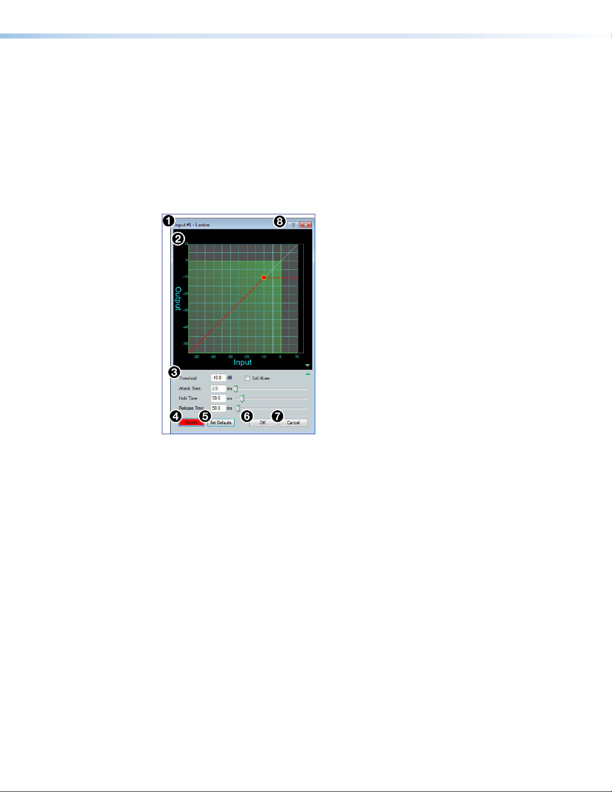
OK Button — (see figure40 on page39) Confirms changes made to the contained
6
parameters and closes the Compressor dialog box.
Cancel Button — (see figure40 on page39) Reverts any changes made to the
7
contained parameters back to their states when the current instance of the Compressor
dialog box was opened and closes the dialog box.
Dynamics Help Button — (see figure40 on page39) Opens the Dynamics
8
Operation topic of the DSPConfiguratorHelp File for further assistance in operating
dynamics processors.
Limiter
Limiter Channel Name
1
Limiter Graph
2
Limiter Parameters List and Control
3
Bypass Button
4
Set Defaults Button
5
OK Button
6
Cancel Button
7
Dynamics Help Button
8
Figure 41. Limiter Dialog Box
Limiter Channel Name — This name changes to match the default or user defined
1
input name.
Limiter Graph — Graphically displays limiter parameter settings. Parameters can also
2
be adjusted using this graph. Click and drag the dot on the graph to adjust the limiter
Threshold.
Limiter Parameters List and Control— Lists all configurable parameters for the
3
limiter.
• Text fields are available to adjust Threshold, Attack Time, Hold Time, and
Release Time.
• Click and drag sliders to adjust Attack Time, Hold Time, and Release Time.
• Click a slider once and use the <Left Arrow> and <Right Arrow> keys to adjust
the respective parameter in 1 ms steps.
• Select the Soft Knee checkbox to provide a more gradual implementation of
limiting when the signal reaches the threshold.
Bypass Button — Bypasses the limiter. When the button is red, bypass is enabled.
4
Set Defaults Button — Resets all limiter parameters to their default values. To view
5
individual parameter default values, see the DSP Configurator Help File by clicking the
Dynamics Help button (8) and navigate to the About Dynamics topic.
OK Button — Confirms changes made to the contained parameters and closes the
6
Limiter dialog box.
NetPA U 2002 SB User Guide • DSP Configurator Software 40
Page 49
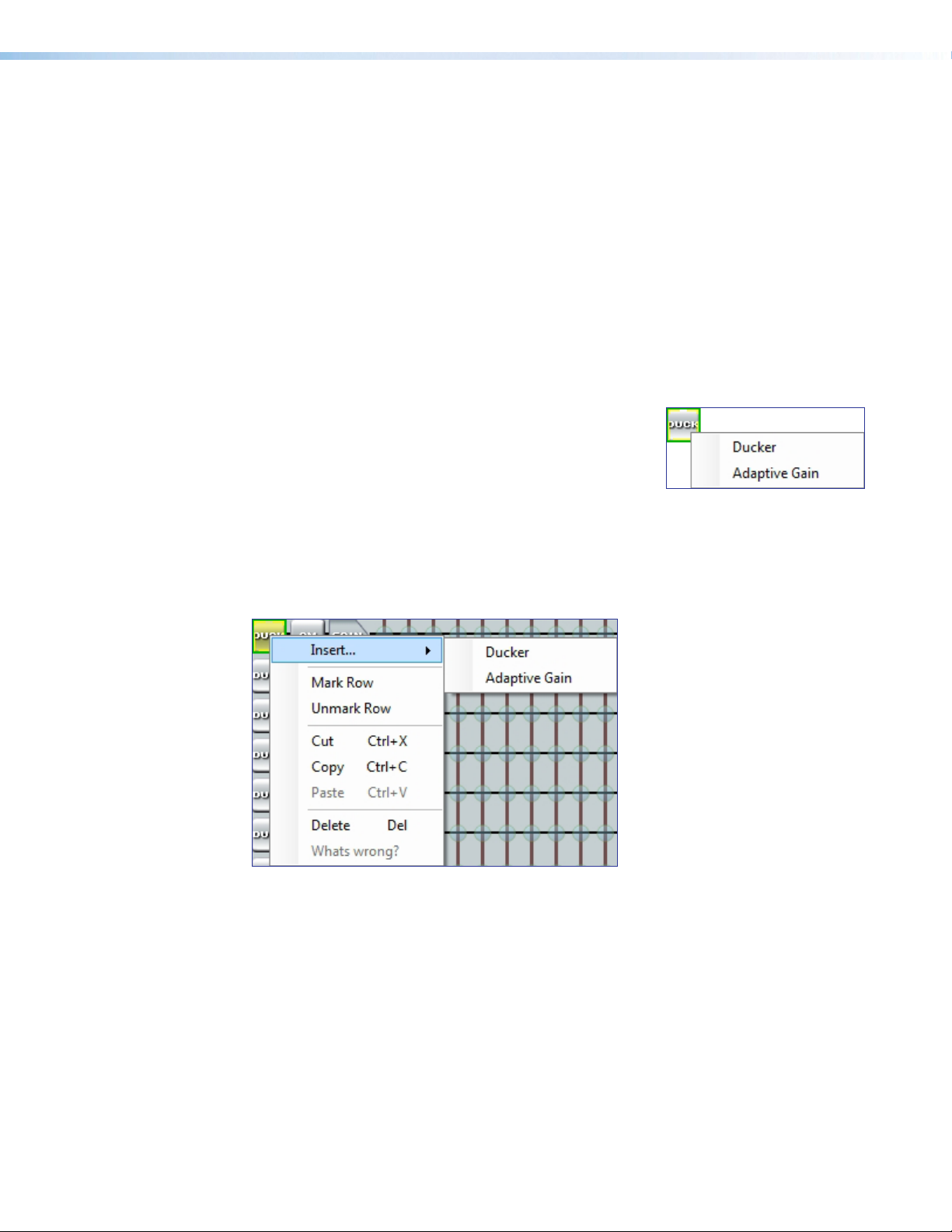
Cancel Button — (see figure41 on page40) Reverts any changes made to the
7
contained parameters back to their states when the current instance of the Limiter
dialog box was opened and closes the dialog box.
Dynamics Help Button — (see figure41 on page40) Opens the Dynamics
8
Operation topic of the DSPConfiguratorHelp File for further assistance in operating
dynamics processors.
Input Ducking Block
The duck block contains a ducking processor as well as an adaptive gain processor.
• Ducker (see page42) — Decreases levels on specified channels when signal is
present above a set threshold on the duck source (trigger).
• Adaptive Gain (see page43) — Increases levels on specified channels when signal
is present above a set threshold on the adaptive gain source channel (trigger).
Double-click the Duck block to open the drop-down list
where the Ducker and Adaptive Gain processors can
be selected.
Select Ducker to insert a ducking processor into the duck
block (as seen on the right). Select Adaptive Gain to
insert an adaptive gain processor into the duck block.
Depending on the processor selected, the duck block
displays DUCK for a ducker or AG for adaptive gain.
If a ducking processor has been inserted and needs to be changed to a an adaptive gain
processor, or vice versa, right-click the block and hover over Insert to insert a different
processor (see figure42).
Figure 42. Changing Ducking Processor
NetPA U 2002 SB User Guide • DSP Configurator Software 41
Page 50
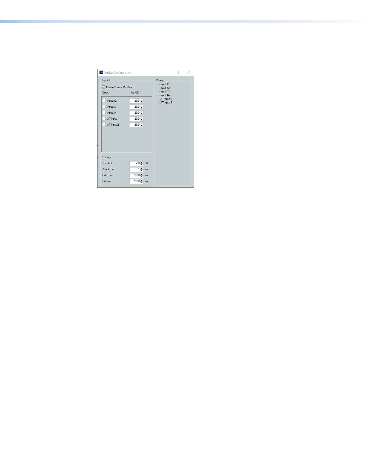
Ducker
After inserting a ducker processor, double-click the Duck icon to open the
Ducker Configuration dialog box.
4
1
2
Figure 43. Ducker Configuration Dialog Box
Duck Source Configuration — The Enable Source Mic/Line checkbox is checked
1
when a ducker is inserted (default). In the Duck column, check the inputs that are
ducked. In the by (dB) column, enter the amount of ducking that occurs on each
channel selected in the Duck column. When the threshold is exceeded on the duck
source, ducking occurs on the selected channels.
Duck Parameter Settings — Contains controls for setting Threshold, Attack Time,
2
HoldTime, and Release. Click the Ducking Operation Help button (4) to open the
DuckingOperation topic in the DSP Configurator Help File.
Duck Priority Tree — Displays the ducking priority for all Input channels. Select
3
another input to populate the Ducker Configuration dialog with the ducker information
for that channel. Channels with an adaptive gain processor are appended with an (AG).
Channels with adaptive gain processors cannot be selected from this dialog box.
Ducking Operation Help Button —Opens the Ducking Operation topic of the
4
DSPConfiguratorHelp File for further assistance in ducker configuration.
3
Duck Source Configuration
1
Duck Parameter Settings
2
Duck Priority Tree
3
Ducking Operation Help Button
4
NetPA U 2002 SB User Guide • DSP Configurator Software 42
Page 51
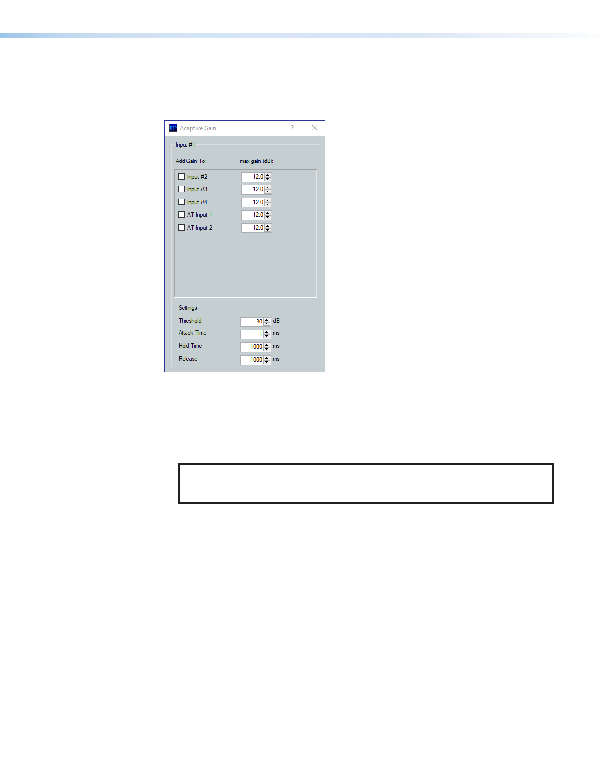
Adaptive Gain
After inserting an adaptive gain processor, double-click the AG icon to open the
Adaptive Gain dialog box.
Adaptive Gain Source Configuration
3
1
1
Adaptive Gain Parameter Settings
2
Adaptive Gain Help Button
3
2
Figure 44. Adaptive Gain Dialog Box
Adaptive Gain Source Configuration — In the Add Gain To column, check the
1
inputs that have gain added by the adaptive gain processor. In the Max Gain (dB)
column, enter the maximum amount of gain applied to each channel selected in the Add
Gain To column. When a box is checked, gain is applied to that channel when signal
exceeds the threshold on the adaptive gain trigger channel.
NOTE: For every 1 dB of signal beyond the level set in the Threshold field, 1 dB of
gain is added to the channels selected in the Add Gain To column. This occurs
until the maximum gain set in the Max Gain (dB) field has been applied.
Adaptive Gain Parameter Settings — Contains controls for Threshold, Attack
2
Time, Hold Time, and Release Time.
Adaptive Gain Help Button — Opens the About Adaptive Gain topic in the
3
DSPConfiguratorHelp File. This help file topic discusses the Adaptive Gain window
in greater detail.
NetPA U 2002 SB User Guide • DSP Configurator Software 43
Page 52
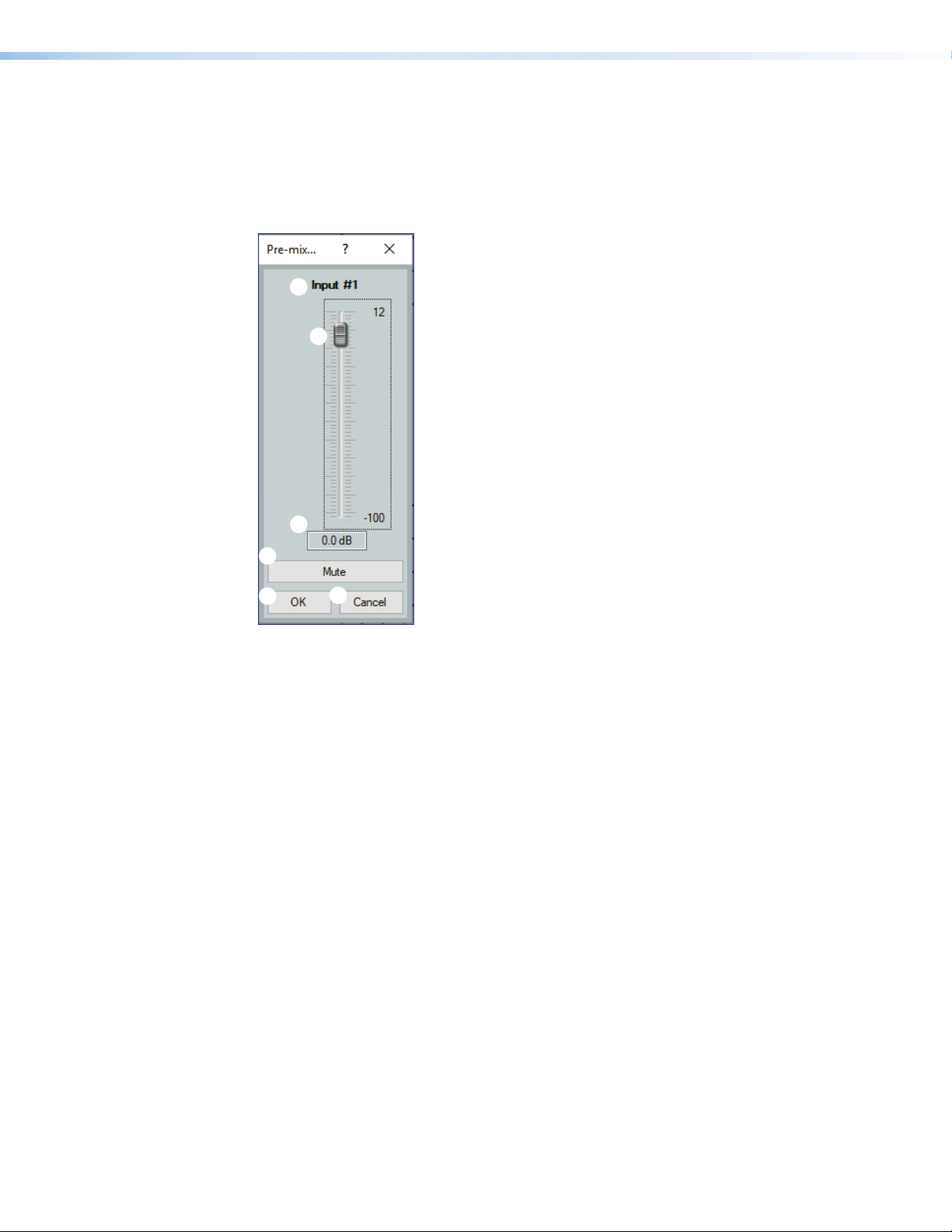
Input Pre-Mixer Gain Block
1
2
3
4
5
6
7
Double-click the pre-mixer Gain block (as seen on the right) to open the
Pre-mixer Gain dialog box.
The Pre-mixer Gain dialog box provides controls to boost, attenuate, and mute the signal
after input processing occurs and before it is sent to the mix matrix.
Input Name
1
Pre-mixer Gain Fader
2
Pre-mixer Gain Text Box
3
Mute Button
4
OK Button
5
Cancel Button
6
Pre-mixer Gain Help Button
7
Figure 45. Input Pre-mixer Gain Dialog Box
Input Name — This name changes to match the default or user defined input name.
1
Pre-mixer Gain Fader — Click and drag the gain fader to provide up to 12 dB of gain
2
or 100dB of attenuation in 1 dB steps. Click the fader and use the <Up Arrow> or
<Down Arrow> keys to adjust the fader up or down in 1 dB steps.
Pre-mixer Gain Text Box — Enter a gain or attenuation value in 0.1 dB steps.
3
Mute Button — Mutes signal at the pre-mixer stage, preventing it from reaching the
4
mix matrices.
OK Button — Confirms changes made to the contained parameters and closes the
5
Pre-mixer Gain dialog box.
Cancel Button — Reverts any changes made to the contained parameters back to
6
their states when the current instance of the Pre-mixer Gain dialog box was opened
and closes the dialog box.
Pre-mixer Gain Help Button — Opens the Pre-mixer Gain topic of the
7
DSPConfiguratorHelp File for further assistance in understanding operating the
Pre-mixer Gain dialog.
NetPA U 2002 SB User Guide • DSP Configurator Software 44
Page 53

AT Inputs
AT inputs receive signal from the Dante network when connected to an audio network. The
NetPA U 2002 SB amplifier can receive 2 channels of audio via Dante.
Renaming an Input
NOTE: Renaming an AT input in DSP Configurator affects the receiver name in
DanteController. Alternatively, renaming a receiver channel name in Dante Controller
affects the name displayed in DSPConfigurator (see Renaming a Receiver or
Transmitter on page43).
1. Click the expansion or AT input name field.
2. Delete or highlight the text and type the desired name.
3. Press the <Enter> key or navigate away from the field to
confirm and apply the new name. Press the <Down Arrow>
key to navigate to and highlight the next name field.
NOTE: Follow the same procedure to edit an AT Input name.
AT Inputs Overview
AT inputs allow an amplifier to receive signal from the
audio network. Network audio routing is done with
Dante Controller (see Dante Controller on page75).
AT Inputs Processing
The AT inputs contain three processor blocks and a meter block in their signal chain:
• Meter Block
• Filter Block
• Dynamics Block
• Compressor Block
• Limiter Block
• Ducker Block
• Ducker Block
• Adaptive Gain Block
• Pre-Mixer Gain Block
NetPA U 2002 SB User Guide • DSP Configurator Software 45
Page 54
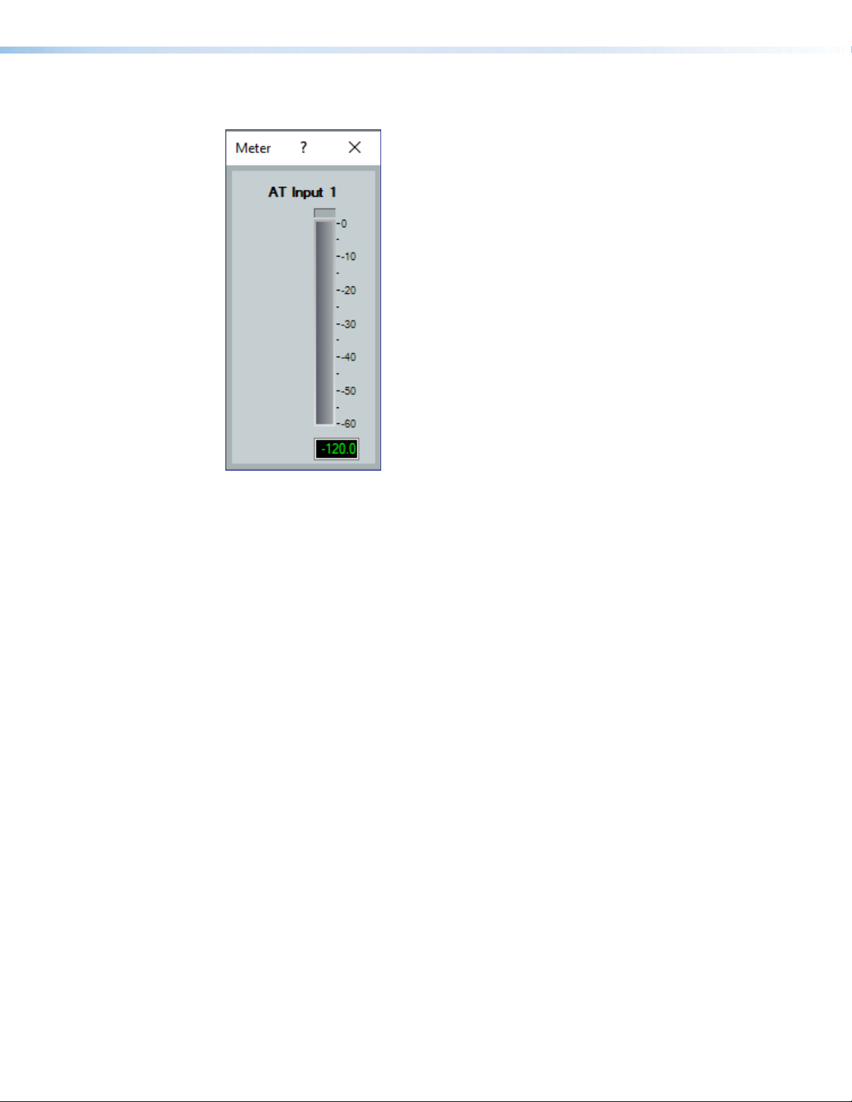
AT Input Meter Block
1
3
2
1
3
2
Figure 46. AT Input Meter Block
AT Input Name — This name changes to match the
default or user defined input name.
AT Input Meter — Provides a readout to view input
activity.
Meter Help Button — Opens the AT Input Meter
topic of the DSPConfiguratorHelp File for further
assistance in understanding operating the AT Input
Meter dialog.
Mix-Points
AT Input Filter Block
The AT input filter block functions the same as the mic/line input filter block (see Input Filter
Block on page37 for information on configuring the virtual return filter block).
AT Input Dynamics Block
The AT input dynamics block functions the same as the mic/line input dynamics block (see
Input Dynamics Blocks on page38 for information on configuring the virtual return
dynamics block).
AT Input Ducker Block
The AT input ducker block functions the same as the mic/line input ducker block (see Input
Ducking Block on page41 for information on configuring the virtual return ducking
block).
AT Input Pre-Mixer Gain Block
The AT input pre-mixer gain block functions the same as the mic/line input pre-mixer gain
block (see Input Pre-Mixer Gain Block on page44 for information on configuring the
virtual return pre-mixer gain block).
DSP Configurator contains six mix matrices that connect all inputs and outputs. The mix
matrices set post-processing mix levels.
Each input is connected to a mix-point for the signal to be routed to an output. In general,
mix levels are set relative to each other, achieving a blend of input signals at an optimal
output level, close to, but not exceeding 0 dBFS at the output.
NetPA U 2002 SB User Guide • DSP Configurator Software 46
Page 55
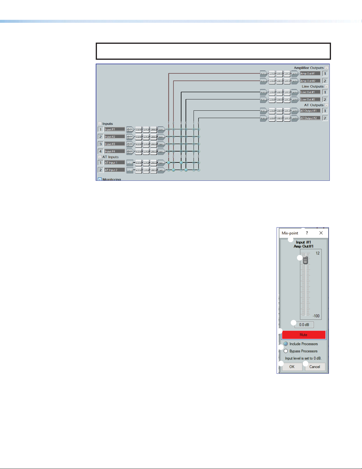
NOTE: In order for mix-points to appear in the workspace, the input group sending
4
signal to the mix-point must be expanded and the input channel must be visible.
Figure 47. DSP Configurator Mix Matrice
Mix-Point Dialog Box
Double-click a mix-point to open the Mix-point dialog box. Alternatively, highlight a
mix-point with a single click and press the <Enter> key to open the Mix-point dialog box.
Mix-point Input and Output — Displays which input (top) and
1
output (bottom) the mix-point is connecting.
Mix-point Fader — Click and drag the mix-point fader to
2
provide up to 12 dB of gain or 100 dB of attenuation in 1 dB
steps. Click the fader and use the <Up Arrow> or <Down
Arrow> keys to change the level in 1 dB steps.
Level Text Box — Allows specific level values to be entered in
3
0.1 dB steps.
Mute Button — Mutes the mix-point (muted by default). When
4
the button is red, the mix point is muted.
Mix Dot Selection — Two radio buttons allow selection of
5
the type of input processing applied to the mix-point. Include
Processors includes signal processing at the mix-point and
marks the mix-dot teal to signify this. Bypass Processors
bypasses signal processing at the mix-point and marks the
mix-dot green to signify signal processing is bypassed.
OK Button — Confirms changes
6
made to the contained parameters and closes the Mix-point
dialog box.
Cancel Button —Reverts any changes made to the contained parameters back to
7
their states when the current instance of the Mix-Point dialog box was opened and
closes the dialog box.
Mix-point Help Button — Opens the Mix-Point topic of the DSPConfiguratorHelp
8
File for further assistance in understanding operating the Mix-Point dialog.
5
6
8
1
2
3
7
NetPA U 2002 SB User Guide • DSP Configurator Software 47
Page 56
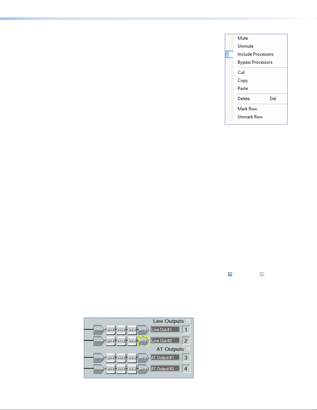
Mix-Point Context Menu
Right-click a mix-point to open the mix-point context menu.
This menu provides quick options to operate mix-points.
Mute — Mutes the mix-point.
1
Unmute — Unmutes the mix-point and creates an
2
audio path between an input and output.
Include Processors — Includes signal processing
3
at the mix-point and marks the mix-dot teal to signify
this.
1
2
3
4
5
6
7
Bypass Processors — Bypasses signal processing
4
at the mix-point and marks the mix-dot green to
signify signal processing is bypassed.
Cut — Cuts the mix-point parameter configuration,
5
preparing it to be pasted to another mix-point. The
parameter configuration information is not removed
until it is pasted to another mix-point.
Copy — Copies the mix-point parameter configuration, leaving the mix-point intact and
6
preparing it to be pasted to another mix-point.
Paste — Pastes a previously cut or copied mix-point parameter configuration to the
7
selected mix-point.
Delete — Deletes the mix-point parameter configuration and mutes the mix-point.
8
8
9
¢
Mark Row — Marks the entire row containing the selected mix-point, highlighting all of
9
Unmark Row — Unmarks the entire row containing the selected mix-point.
¢
DSP Configurator Outputs
The outputs run along the top right of the main workspace in DSP Configurator. There are
two types of outputs available:
Line/AT Outputs
• Line/AT Outputs
• Amplifier Outputs
These outputs receive signal when mix-point connections are made between an input and
an output in the mix-matrices.
Each output panel can be expanded or collapsed by clicking the (expand) or (collapse)
buttons.
The NetPA U 2002 SB has two separate channels for the line outputs and two separate
channels for the AT outputs. Each output has to be routed to individually.
the elements.
Figure 48. Outputs Panel
NetPA U 2002 SB User Guide • DSP Configurator Software 48
Page 57
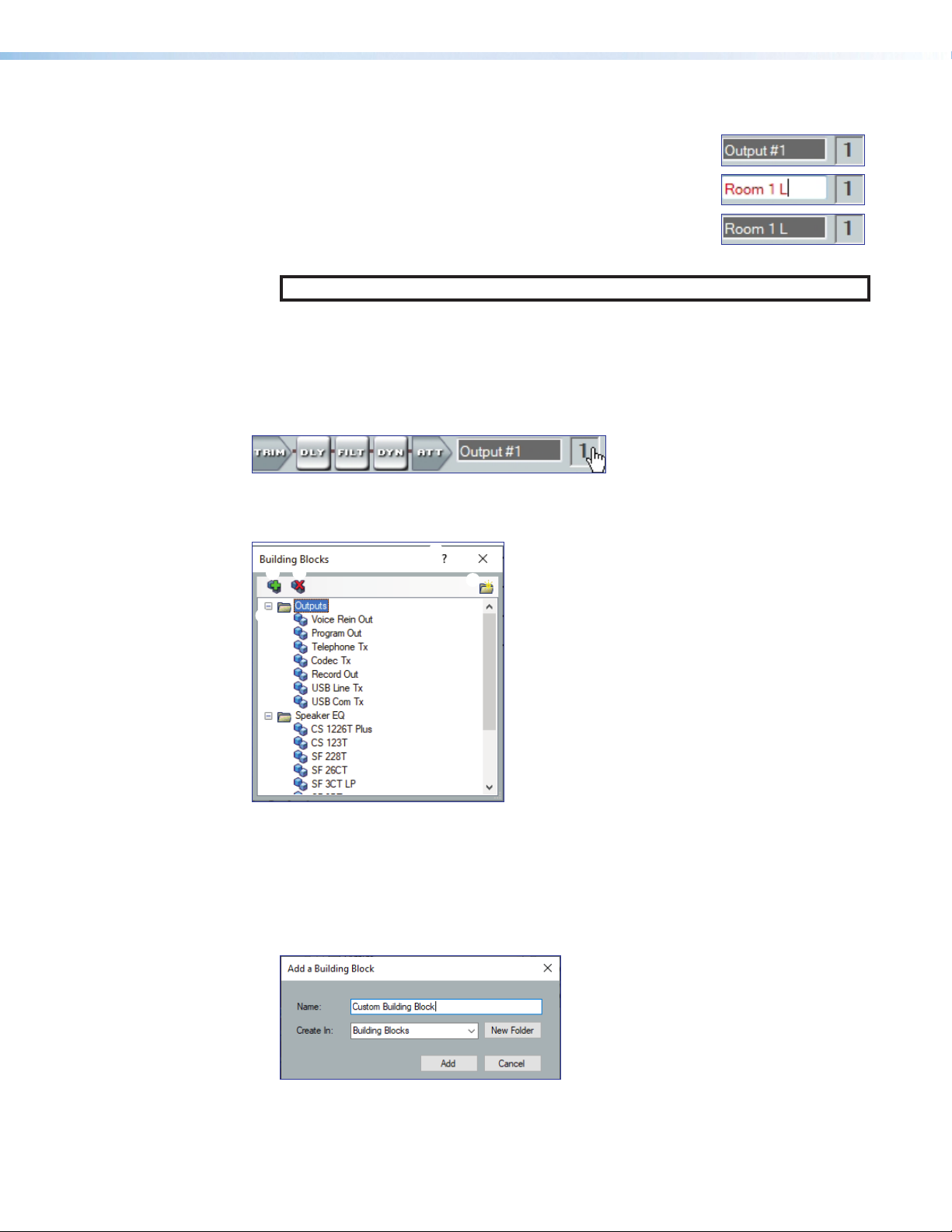
Naming an Output
1. Click the output name field.
2. Delete the text and type the desired output name.
3. Press the <Enter> key or navigate away from the field to
confirm and apply the new output name. Press the <Down
Arrow> key to navigate to and highlight the next name field.
NOTE: Follow the same procedure to edit an Output name.
Line/AT Output Building Blocks
Extron building blocks are a quick configuration tool that can significantly reduce
configuration time. A building block is a collection of processor and gain settings for an
input or output processing chain. These building blocks have been built by Extron based on
extensive use and testing with each intended application or specific device.
Figure 49. Accessing Building Blocks on an Output
Click the output number to open the Building Blocks dialog box.
5
2 3
1
Figure 50. Output Building Blocks Dialog Box
Output Building Blocks List — Contains building blocks for output channels.
1
Add a Building Block Button — Allows users to create custom building blocks,
2
saving the currently applied gain and processor settings on the selected channel. Click
the icon to open the Add a Building Block dialog box. This allows users to name
the new custom building block and choose the folder to save the block to an existing
folder, or create a new folder.
4
Output Building Blocks List
1
Add a Building Block Button
2
Delete a Building Block Button
3
New Folder Button
4
Building Blocks Help Button
5
Figure 51. Add a Building Block Dialog Box
NetPA U 2002 SB User Guide • DSP Configurator Software 49
Page 58

Delete a Building Block Button — (see figure50 on the previous page) Deletes the
1
2
3
4
5
1
2
3
4
5
3
currently selected building block or building block folder. If default building blocks are
deleted, they can be restored from the Organize Building Blocks dialog box.
New Folder Button — (see figure50 on the previous page) Creates a new folder or
4
sub-folder.
Building Blocks Help Button — (see figure50 on the previous page) Opens the
5
Building Blocks topic of the DSPConfiguratorHelp File. This topic contains more
information on the different types of building blocks for inputs and outputs.
Line/AT Output Processing
The output processing chain in DSP Configurator is represented by a string of blocks (see
figure52). Each block contains a specific processor or type of processor. Each output
contains the following processor chain:
• Line/AT Output Trim Block
• Line/AT Output Delay Block
• Line/AT Output Filter Block
• Line/AT Output Dynamics Block
• Line/AT Output Attenuation Block
Figure 52. Output Processing Chain
Line/AT Output Trim Block
Double-click the output Trim block to open the Post-mixer Trim dialog box.
The Post-mixer Trim dialog box provides pre-processing gain and attenuation control for
the selected output.
Output Name — This name changes to match the default or
1
user defined output name.
Post-mixer Trim Fader— Click and drag the trim fader to
2
provide up to 12 dB of gain or 12dB of attenuation in 0.1
dB steps. Click the trim fader and use the <Up Arrow> or
<Down Arrow> to adjust the fader up or down in 0.1 dB steps.
Post-mixer Trim Text Box — Allows the user to enter a gain
3
or attenuation value in 0.1 dB steps.
OK Button — Confirms changes made to the contained
4
parameters and closes the Post-mixer Trim dialog box.
Cancel Button— Reverts any changes made to the contained
5
parameters back to their states when the current instance of
the Post-mixer Trim dialog box was opened and closes the
dialog box.
NetPA U 2002 SB User Guide • DSP Configurator Software 50
Page 59

Line/AT Output Delay Block
1
Double-click the Delay block to open the delay drop down. Click
Delay to insert the delay processor into the block.
Once a delay processor is inserted into the Delay block, double-click the block to open the
Delay dialog box.
Delay Channel Name
1
Units of Measurement
2
Delay Fader and Text Box
3
Temperature Panel
4
OK Button
5
Set Defaults
6
Cancel Button
7
Bypass Button
8
Delay Help Button
9
3
2
4
5
9
7
6
Figure 53. Delay Dialog Box
Delay Channel Name — The name changes to match the default of user defined
1
output name.
Units of Measurement — Radio buttons change the unit of measurement used by the
2
delay fader and text box. Samples, Milliseconds, Feet and Meters are available
units of measurement. Values are converted when the unit of measurement is changed.
Changing the unit of measurement does not alter the amount of delay applied to the
signal.
Delay Fader and Text Box — Adjust the amount of delay applied to the signal. Click
3
and drag the fader up or down to increase or decrease the amount of delay. Click the
fader once and use the <Up Arrow> or <Down Arrow> to adjust delay in 1 sample steps
(or the 1 sample equilvalent in milliseconds, feet, or meters). Use the text box below the
fader to input a delay value.
Temperature Panel — Becomes available when using delay in feet or meters.
4
Compensates delay for ambient temperature in the acoustic space. Temperature is not
available when using samples or milliseconds as the unit of measurement.
OK Button — Confirms changes made to contained parameters and closes the Delay
5
dialog box.
Set Defaults Button — Resets the delay to the default setting.
6
Cancel Button — Reverts any changes made to the contained parameters back to
7
their states when the current instance of the Delay dialog box was opened and closes
the dialog box.
Bypass Button — Bypasses the delay. When the button is red, bypass is enabled.
8
Delay Help Button — Opens the Delay Operation topic of the DSP Configurator
9
Help File for further assistance in understanding operating the delay processor.
8
Line/AT Output Filter Block
One filter block is available for each output channel. This filter block functions the same
as the mic/line input filter block (see Input Filter Block on page37 for information on
configuring output filters).
NetPA U 2002 SB User Guide • DSP Configurator Software 51
Page 60

Line/AT Output Dynamics Block
3
7
8
One dynamics block is available for each output channel. This block functions the same
as the mic/line input dynamics block (see Input Dynamics Blocks on page38 for
information on configuring the output dynamics block).
Line/AT Output Attenuation Block
Double-click the output Attenuation block to open the Attenuation dialog
dialog box.
The Attenuation dialog box provides attenuation control for the selected output.
Output Name
1
Output Attenuation Fader
1
4
2
2
Output Attenuation Text Box
3
dBFS Meter
4
dBFS Text Readout
5
Polarity Button
6
Mute Button
7
OK Button
8
Cancel Button
9
5
6
9
Figure 54. Attenuation Dialog Box
Output Name — This name changes to match the default or user-defined output name.
1
Output Attenuation Fader — Click and drag the trim fader to provide up to 100dB of
2
attenuation. Click the trim fader and use the <UpArrow> or <DownArrow> to adjust
the fader up or down in 1 dB steps.
Output Attenuation Text Box — Allows the user to enter a gain or attenuation value in
3
0.1 dB steps.
dBFS Meter — Provides post-attenuation and pre-mute a readout of the output signal
4
level.
dBFS Text Readout — Displays a numerical readout of the output signal level.
5
Polarity Button — Click this button to invert the signal polarity of the selected output.
6
When the button displays the black + symbol on a gray field ( ), the polarity is normal.
When the button displays the black - symbol on a yellow field ( ), the polarity is
inverted.
Mute Button — Mutes the signal at the output stage.
7
OK Button — Confirms changes made to the contained parameters and closes the
8
Attenuation dialog box.
Cancel Button — Reverts any changes made to the contained parameters back to
9
their states when the current instance of the Attenuation dialog box was opened and
closes the dialog box.
NetPA U 2002 SB User Guide • DSP Configurator Software 52
Page 61
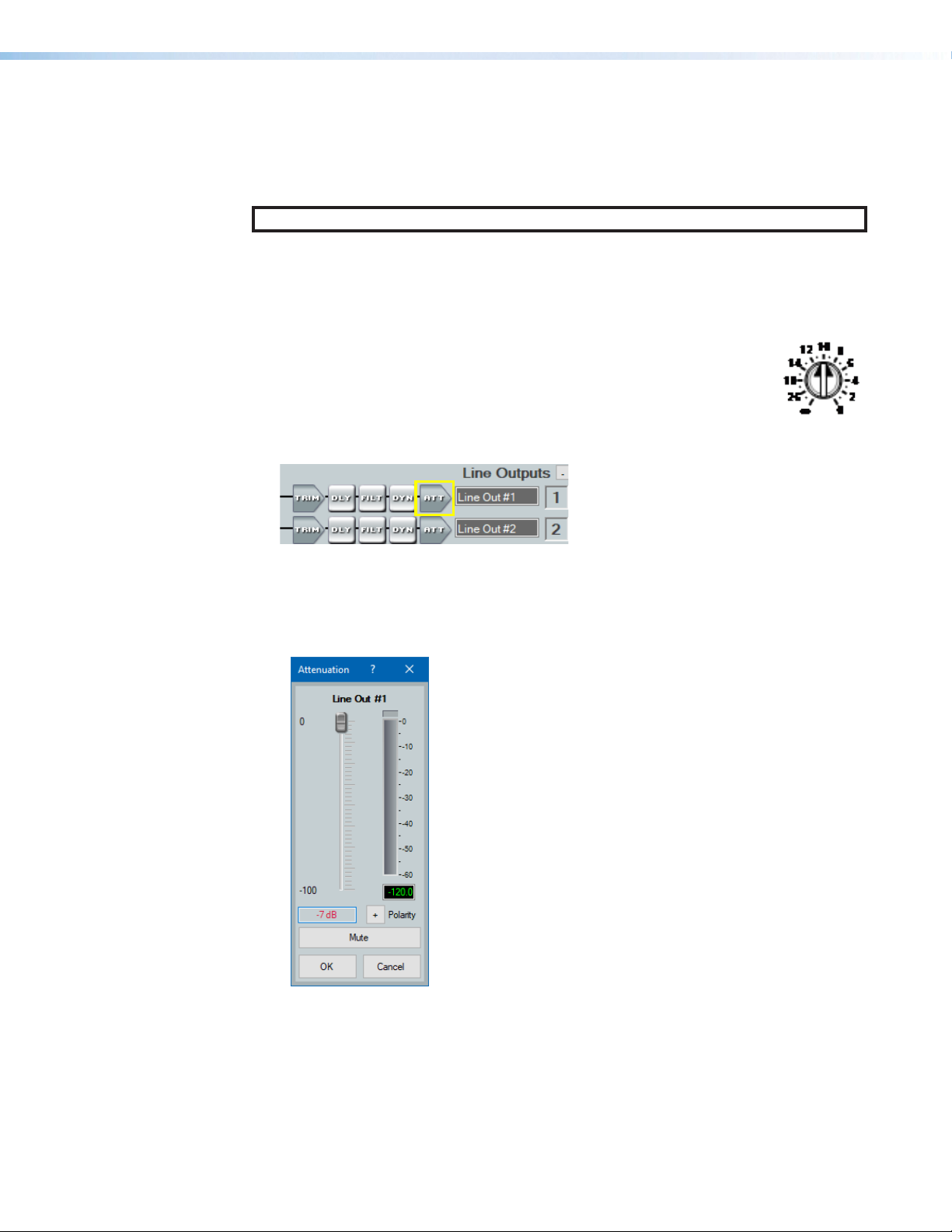
Balancing NetPA Amplifier Output Level and XPA Input Sensitivity
3
Setting proper gain structure is necessary to ensure maximum audio clarity and amplifier
output performance. To properly balance the input sensitivity of XPA amplifiers, when used
in conjunction with NetPA Ultra Series amplifiers, follow the steps outlined below.
NOTE: When setting levels, pay attention to avoid digital clipping.
The following is an example of how to adjust the NetPA U 2002 SB internal amplifiers to
match an external XPA amplifier connected to the NetPA U 2002 SB line outputs:
1. Ensure the NetPA U 2002 SB outputs are properly connected to the XPA amplifier
inputs. Refer to the NetPA U 2002 SB User Guide and XPA User Guide found on www.
extron.com for more details on connecting the amplifiers.
2. Set the attenuation potentiometer on the XPA input to -10 dB (12 o’clock
position), as seen in the image to the right.
3. Open DSP Configurator and connect live to the NetPA U 2002 SB.
4. Double-click the Line Output ATT block (highlighted in yellow) to open the attenuator
dialog box, as shown below in figure 55.
Figure 55. Line Outputs Block
5. Set the Line Output attenuator(s) to -7 dB, as shown in figure 56, below. The
attenuation value can be adjusted by either dragging the fader (1), or clicking in the
display box (2), and manually entering the desired value.
6. Click OK (3) to apply the change and close the dialog box.
7. Double-click the Amplifier Output ATT block (highlighted in yellow) to open the
1
2
Figure 56. NetPA 2002 SB Line Out Dialog Box
attenuator dialog, as shown in figure57 on the next page.
NetPA U 2002 SB User Guide • DSP Configurator Software 53
Page 62

Figure 57. Amplifier Outputs Block
3
8. Set the Amp Out attenuator(s) to 0 dB, as shown in figure 58, below. The attenuation
value can be adjusted by either dragging the fader (1), or clicking in the display box
(2), and manually entering the desired value.
1
2
Figure 58. NetPA U 2002 SB Amp Out Dialog Box
Amplifier Outputs
Setting the Output Mode
9. Click OK (3) to apply the change and close the dialog box.
The NetPA U 2002 SB output mode is configured via DSP Configurator and the selection
is passed to the amplifier board. There are six selectable modes that are divided into two
stereo modes and four bridged mono modes.
• Stereo Modes (8 ohm/4 ohm) — Each channel of a output pair behaves
independently. A channel’s level is set by its dedicated attenuator. Input sensitivity in
either stereo mode is 0 dBFS.
• Bridged Mono Modes — There are four bridged mono modes: two low-impedance (8
ohm and 16 ohm) and two high-impedance (70V and 100V). The second output will not
be user-controllable in DSP Configurator.
• 8 ohm bridged — This mode bridges the output pair and sets it for an 8 ohm load.
• 16 ohm bridged — This mode bridges the output pair and sets it for a 16 ohm
load.
• 70V — This mode bridges the output pair and sets it for a 70V load.
• 100V — This mode bridges the output pair and sets it for a 100V load.
NetPA U 2002 SB User Guide • DSP Configurator Software 54
Page 63

Bridging occurs in the amplifier stage. Channel 1’s positive pin becomes the bridged
output’s positive pin, and Channel 2’s positive pin becomes the bridged output’s negative
pin.
When the amplifier is set to bridged mono mode, DSP Configurator will delete the Channel 2
amplifier output signal chain, including mix points and output processors.
In the 70V and 100V modes, an 80Hz, 12 dB/octave high-pass filter is applied to the output
filter block by default. The user can change this filter. In all other modes, the high-pass filter
is not applied by default.
Configuring the Output Mode
1. Select Tools > Configure Amplifier Output Mode to open the Configure
Amplifier Output Mode dialog box.
Figure 59. Configure Amplifier Output Mode Dialog Box
Select the radio button next to the desired output mode. The currently selected mode
is indicated with an asterix (*) to the right. The information window to the right of the
output mode list displays the DSP and amplifier output settings that will change when
the mode settings are applied.
2. Click Apply to apply the amplifier output mode settings to the device. The Confirm
Amplifier Output Mode Selection dialog box will open.
Figure 60. Confirm Amplifier Output Mode Selection Dialog Box
3. Click Yes to confirm the amplifier output mode selection and apply it to the amplifier.
NetPA U 2002 SB User Guide • DSP Configurator Software 55
Page 64
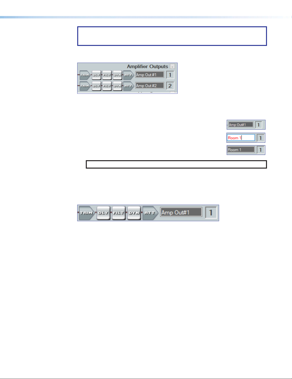
ATTENTION: Verify that the output connector wiring and speaker configuration
matches the new output mode before proceeding to avoid damage to the speakers
and/or amplifier malfunction prior to clicking Yes.
The NetPA U 2002 SB features two processing paths to the amplifier outputs. All audio
inputs can be routed to an amplifier output via discrete amplifier output mix-points.
Figure 61. Amplifier Output Panel
Naming an Amplifier Output
1. Click the Amplifier Output name field.
2. Delete the text and type the desired Amplifier Output name.
3. Press the <Enter> key or navigate away from the field to
confirm and apply the new output name. Press the <Down Arrow>
to navigate to and highlight the next name field.
NOTE: Follow the same procedure to edit an output name.
Amplifier Outputs Processing
The amplifier output processing chain in DSP Configurator is represented by a string of
blocks as seen in figure 62, below. Each block contains a specific processor or type of
processor.
Figure 62. Amplifier Output Processing Chain
The processor chain is as folllows:
• Amplifier Output Trim Block — One trim block is available for each amplifier output
channel. The trim block functions the same as the line/AT output trim block (see Line/
AT Output Trim Block on page50 for information on configuring output filters).
• Amplifier Output Delay Block — One delay block is available for each amplifier
output channel. The delay block functions the same as the line/AT output delay block
(see Line/AT Output Delay Block on page51 for information on configuring output
filters).
• Amplifier Output Filter Block — One filter block is available for each amplifier output
channel. This filter block functions the same as the line/AT output filter block (see Line/
AT Output Filter Block on page51 for information on configuring output filters).
• Amplifier Output Dynamics Block — One dynamics block is available for each
amplifier output channel. This block functions the same as the line/AT input dynamics
block (see Line/AT Output Dynamics Block on page52 for information on
configuring the output dynamics block).
• Amplifier Output Attenuation Block — One attenuation block is available for each
amplifier output channel. The attenuation block functions the same as the line/AT
output attenuation block (see Line/AT Output Attenuation Block on page52 for
information on configuring output filters).
NetPA U 2002 SB User Guide • DSP Configurator Software 56
Page 65
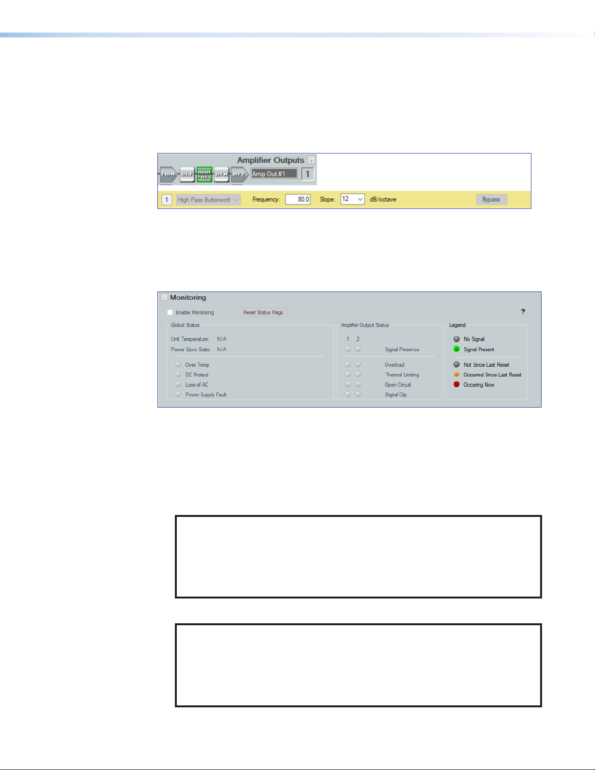
Monitoring
• High-Pass Filter Information — For bridged mono 70V or 100V output modes, a
fixed high-pass filter is inserted into the output chain of the amplified output. This filter
takes up one of the filter slots in the output filter block. This high-pass filter is inserted
to prevent the saturation of the transformer cores in the 70V/100V speaker chain by
low frequency content. The filter corner frequency and slope can be adjusted. The
frequency adjustment has a lower limit of 35 Hz. The filter cannot be deleted, and the
filter type cannot be changed.
Figure 63. High-Pass Filter
The monitoring section of the workspace contains read-only information about the
NetPAUltra device.
1 2
7
3
5
4
Enable Monitoring
1
Check Box
Reset Flag Status
2
Button
Figure 64. Monitoring Panel
Enable Monitoring Check Box — To enable the monitoring feature, click this check
1
box.
NOTE:
• Enabling monitoring in DSP Configurator only enables it while using
DSP Configurator.
• Enabling monitoring does not enable or disable unsolicited responses.
• For details on using the monitoring feature outside of DSPConfigurator, see
Status on page58.
Reset Flag Status Button — Click this button to reset all status flags.
2
NOTE:
• If the fault condition is still occurring, the flag remains red following the reset.
• Status flags are reset when power is cycled.
• Once a system has been serviced to address a fault, the status flags should
be reset, either all at once through the reset status flag button, SIS, or
individually through SIS.
Global Status
3
Section
Global Status
4
Faults
6
Amplifier Output
5
Status Section
Fault Statuses
6
Section
Legend
7
NetPA U 2002 SB User Guide • DSP Configurator Software 57
Page 66

Global Status Section —(see figure64 on page57)
3
• Unit temperature — Displays the internal temperature of the amplifier at a
particular location.
• Power Save State — Indicates the standby state that the amplifier is currently in.
• Active (Auto Timer Disabled) — The Auto-Standby Timer is disabled, and
the amplifier does NOT automatically enter standby mode when no active
signal is present on any amp channel for 25 minutes.
• Active (Auto Timer running but not triggered) — The Auto-Standby Timer
is enabled. The amplifier remains active while there is an active signal on any
amp channel. The amplifier enters standby mode if no active signal is present
on any amp channel for 25 minutes. It returns to active upon detection of signal
on any amp channel. When the SIS command is sent, the timer resets.
• Standby (SIS triggered) — When the amplifier is forced into Standby via SIS
through DSP Configurator or a control system, the unit does not wake from
standby until the amplifier is placed into Standby Mode 0 or 1 (Active [Auto
Timer Disabled] or Active [Auto Timer running but not triggered], respectively)
the same way, regardless of signal presence.
• Standby (Timer triggered) — The amplifier has entered standby mode
because no active signal was present on any amp channel for 25 minutes. It
returns to active upon detection of signal on any amp channel.
• Standby (Contact Closure triggered) — The amplifier has been forced into
standby via the STANDBY port (contact closure), and remains in this state until
the contact is opened. Once opened, the amplifier returns to its last known
active standby state. This function overrides all other standby conditions.
Global Status Faults — (see figure64 on page57) These are faults that are not
4
specific to an amplifier channel, see table below for details on the specific faults.
Status Possible Triggers Possible Causes Possible Solutions
Over Temp
DC Protection
The amplifier has
exceeded the
recommended operating
temperature.
See specifications on the
Extron website, www.
extron.com.
A DC signal has been
detected on an amplifier
channel.
The ambient
environment exceeds the
recommended operating
temperature.
Hardware failure.
• Verify that the placement of
the amplifier allows for suitable
ventilation and airflow
• Avoid placing equipment on
top or below the amplifier.
• Verify that the operating
temperature is within the
specified range.
• Disconnect power then
reconnect power to the
unit to determine if the unit
immediately goes into standby
upon power up
• The amplifier may need to be
serviced.
NetPA U 2002 SB User Guide • DSP Configurator Software 58
Page 67

Status Possible Triggers Possible Causes Possible Solutions
Loss of AC
• If a “2” is reported:
Loss of AC is
detected.
• If a “1” is reported:
A momentary loss of
AC power has been
detected in the past.
There is or has been a
disruption in power.
Check the system power
distribution.
Main power supply
fault
Status Possible Triggers Possible Causes Possible Solutions
Output Thermal
limiting
The main power supply
has shut down for reasons
other than loss of AC,
going into standby, or DC
protect and is effectively
muting all output channels.
Amplifer Output Status Section — (see figure64 on page57)
5
Signal Presence Section — Indicates the presence of or lack of a signal on a
particular channel.
• Green when the audio signal crosses the signal detection threshold of the output
channel (−60 dBFS).
• Gray when the audio signal does not cross the signal detection threshold of the
output channel.
FaultStatuses Section — (see figure64 on page57) These are faults specific to
6
an amplifier channel, see table below for details on the specific faults.
The specified
amplifier channel has
overheated and is
muting the affected
channel.
• The power supply has
overheated.
• There is a damaged
component.
• The channel is driving
too low of a speaker
load impedance.
• The channel is being
fed a heavily clipped or
distorted signal.
• The amplifier operating
environment exceeds
the recommended
operating temperature.
• Allow the amplifier to cool
down.
• Make sure the correct speaker
load is connected.
• Check that speakers are
tapped appropriately.
• Recheck the amplifier gain
structure.
• Verify that the amplifier ambient
environment does not exceed
the recommended operating
temperature (see suggestions
for Over Temp).
• Make sure the correct speaker load
is connected.
• Check that speakers are tapped
appropriately.
• Recheck the amplifier gain
structure.
• Verify that the amplifier ambient
environment does not exceed
the recommended operating
temperature (see suggestions for
Over Temp).
NetPA U 2002 SB User Guide • DSP Configurator Software 59
Page 68

Status Possible Triggers Possible Causes Possible Solutions
Overload
Open Circuit
Digital clip
Unit is in standby
• The current or
power limiter has
been triggered.
• A short on the
affected output
channel has been
detected.
The affected channel
has detected an open
circuit.
Audio output sounds
distorted.
The unit has been
placed into standby.
Legend — (see figure64 on page57)
7
• Red — The amplifier is actively detecting a fault.
• Yellow — The amplifier is not actively detecting a fault, but one has been detected
since the last time the status flags were reset.
• Gray — The amplifier has never detected a fault.
• Too much current is
being drawn due to
overdriving the output.
• An improper speaker
load has been
attached (for example,
attaching a low
impedance speaker
to a high impedance
output).
• The output has been
shorted.
• The connection to the
speaker chain has
been broken.
• An improper speaker
load has been
attached (for example,
attaching a high
impedance speaker
to a low impedance
output).
• No speaker load is
attached.
The output DAC is being
overdriven.
• The auto-standby
timer has timed out.
• The contact closure
port is engaged on the
rear panel.
• SIS has forced the unit
into standby.
• DC has been detected
on an output.
• Recheck the amplifier gain
structure.
• For low-impedance loads: Verify
that total impedance at the amplifier
is ≥ 4 ohms.
• For 70V/100V speaker loads:
Recheck speaker taps.
• Check for shorts at the output and
throughout the speaker chain.
• Check for an open circuit at the
output and throughout the speaker
chain.
• Recheck speaker taps.
Recheck the amplifier gain structure.
• Check that there is sufficient signal
going to the amplifier channel.
• Check that the standby port is not
engaged.
• Check that the SIS is not forcing
the unit into standby.
• If none of the above work, check
for a DC fault (see suggestions for
DCprotection).
NetPA U 2002 SB User Guide • DSP Configurator Software 60
Page 69

Open Circuit Detect
For high impedance amplifiers, open circuit detect requires that the speaker chain be
tapped at a minimum of 32 Watts for 70 V systems and 64 Watts for 100 V systems.
For this detection circuit to function, adequate audio signal must be present at the output
channel. The output attenuation meters should be bouncing above -50 dBFS.
If at any point an open circuit is detected (yellow or red status), the system should be
inspected.
Loss of AC
Since status flags are reset after a power cycle, the amplifier only reports this fault for the
short time it remains active after it loses power. This is generally enough time for it to report
loss of power to DSP Configurator before disconnecting. Once power is restored and DSP
Configurator reconnects, the indicator is gray.
In the event that this status is yellow while DSP Configurator is connected to the amplifier,
this represents a short disruption in power.
NetPA U 2002 SB User Guide • DSP Configurator Software 61
Page 70
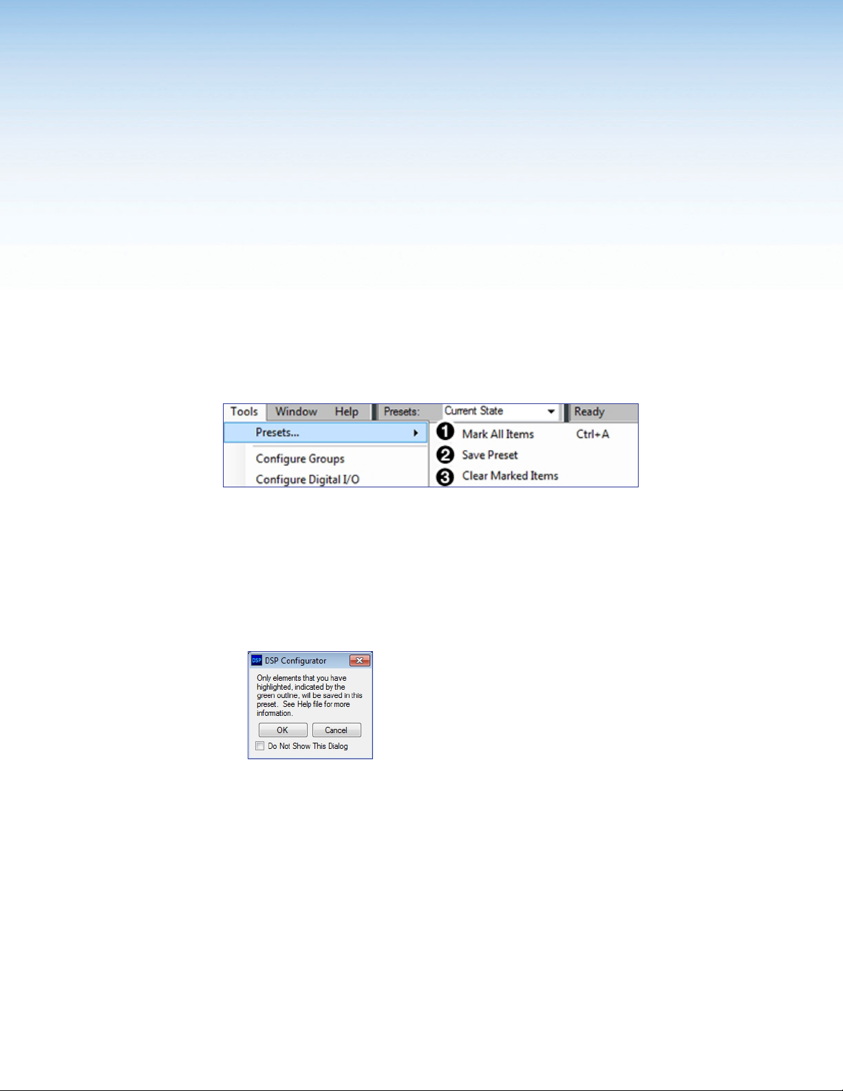
Configuration Tools
This section contains information for configuring certain tools and options that are found
under the Tools menu in DSP Configurator and covers the following topics:
Presets
• Presets
•
Groups
•
Device Manager
Preset options are available from the Tools menu.
Figure 65. Presets Options
•
Connect/Disconnect from Device
•
Firmware Loader
•
Organize Building Blocks
•
Device Settings
•
Dante Device
•
Options
Mark All Items — Marks all gain blocks, processor blocks, and mix-points in the main
1
workspace. Performing this function before saving a preset ensures every element in the
workspace is saved to the preset.
Save Preset — Saves the marked blocks and mix points of the current configuration
2
as a preset. When Save Preset is clicked, the following dialog box opens saying that
only the elements marked with a green outline are saved to the preset (see figure 66).
This option is only available if items are marked.
Figure 66. Preset Save Message
Clear Marked Items — Unmarks all currently marked elements.
3
Methods for Marking Items
Marked items are highlighted in green (see figure66 on page63). There are four ways to
mark items in DSP Configurator:
• Mark All — Press <Ctrl+A> on the keyboard to mark all items in the main workspace.
• Mark Group — Click and drag the cursor to create a box around a group of items to
mark them. Click and drag the cursor while holding the <Shift> key to create box
around another group of items to mark them while keeping previous group marked.
• Mark Series — Click the first item in the series to mark it, then press <Shift+Click>
on the final item in the series. All items between the first and last items are marked.
NetPA U 2002 SB User Guide • Configurator Tools 63
Page 71
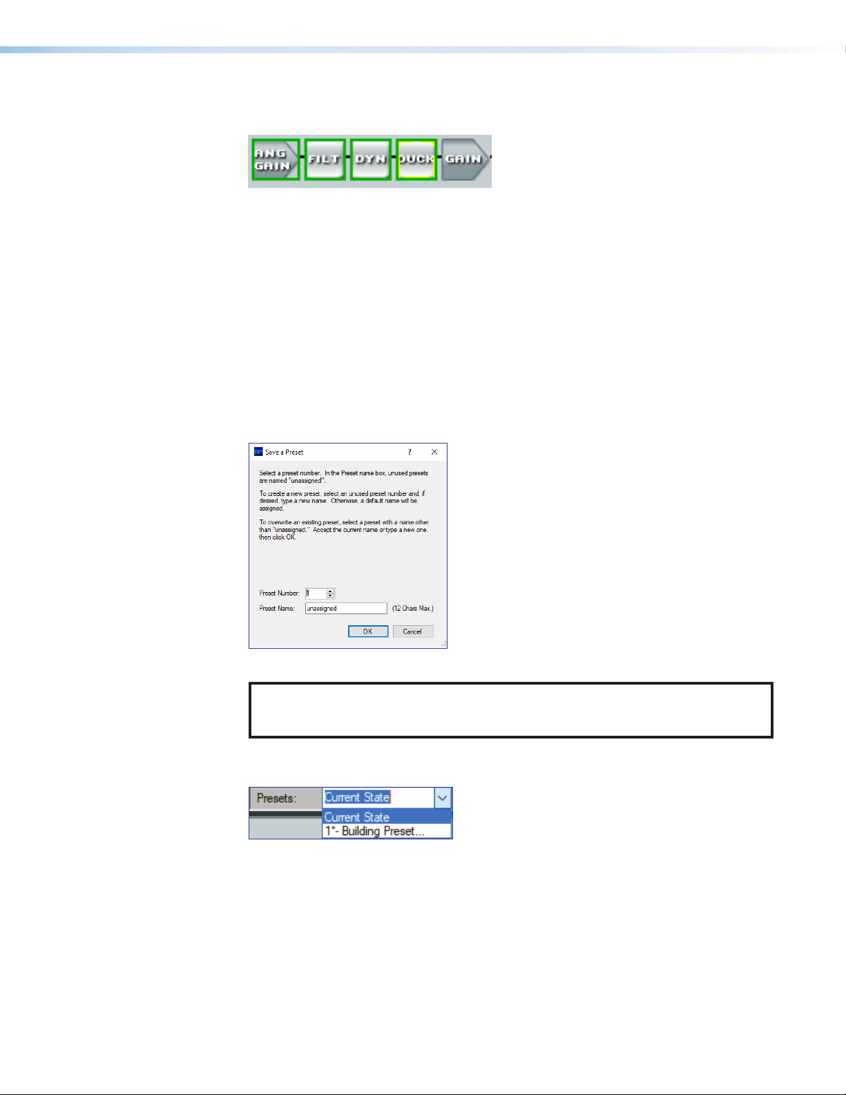
• Mark Multiple Individual – Click the first item to mark it and press <Ctrl+Click> to
1
2
3
mark additional items anywhere in the main workspace.
Figure 67. Marked Items Highlighted in Green
Configuring Presets
1. Create a configuration to be saved as a preset (see Tools on page29).
2. Mark the items to be included in the preset.
3. Select Tools > Presets > Save Preset.
4. From the Save a Preset dialog box, enter the preset number (1 through 8) in the
Preset Number field (see figure67, 1). Preset slots that do not already have a preset
assigned read [unassigned]. Enter a name into the Preset Name field (2, 12
character maximum).
5. Click OK (3) to save the preset.
Figure 68. Save a Preset Dialog Box
NOTE: When a configuration file is pushed to a NetPA Ultra Series amplifier, presets
contained within that file are available for recall from DSP Configurator or SIS
commands.
6. The preset is saved and is available from the Presets drop-down list at the top of the
main workspace.
Figure 69. Presets Drop-Down
NetPA U 2002 SB User Guide • Configurator Tools 64
Page 72
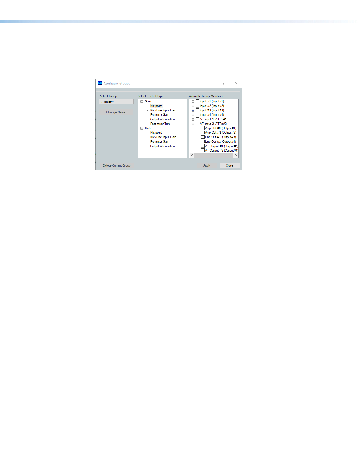
Groups
Groups allow master control of Gain and Mute for groups of channels. Groups are used in
control configurations.
Click Tools > Configure Groups to open the Configure Groups dialog box.
1
2
3
4
7
56
Select Group
1
Select Control Type
2
Available Group Members
3
Change Name Button
4
Figure 70. Group Controls Dialog Box
Select Group — Provides a drop-down menu to select the number of the group to
1
be configured. If the group has been configured and named, the group name appears
next to the group number. If the group slot is empty, it reads <empty> next to the group
number. There are 32 group slots available.
Select Control Type — Group controls can manage Gain and Mute for the specified
2
inputs, mix-points, or outputs. From the Select Control Type panel, select the type
of control from the Gain or Mute lists.
Available Group Members — This section populates according to the selected
3
control type and lists all inputs, mix-points, and outputs available to be added as group
members. Check the box next to a member to add it to the group. Group members
must be the same control type. The maximum number of group members for a single
group is 8.
Change Name Button — Once a group has been created, select it from the Select
4
Group drop-down list (1), click Change Name to change the name of the selected
group.
Apply Button — Click Apply after changes to a group have been made. The Confirm
5
Group Details dialog box opens allowing the group name and number to be edited.
Click OK to apply group changes.
Delete Current Group Button — Select a group from the Select Group drop-down
6
list and click Delete Current Group to delete the group.
Close Button — Click Close to close the dialog box. Any changes that have not been
7
applied are lost.
Apply Button
5
Delete Current Group Button
6
Close Button
7
NetPA U 2002 SB User Guide • Configurator Tools 65
Page 73

Configuring Groups
4
To create a new group:
1. Select Tools > Configure Groups to open the Configure Groups dialog box.
2. From the Select Group drop-down, select a group slot to configure (see figure70,
, on the previous page).
1
3. From the Select Control Type panel (2), expand a control type.
4. Choose which gain stage the control type affects.
5. From the Available Group Members panel, select the channels to be configured as
group members (3).
6. Click Apply (4).
1 2 3
Figure 71. Configure Groups Dialog Box
7. Confirm the group number and name from the Confirm Group Details dialog box
(see figure71, 5).
8. Click OK to confirm all details and create the group (6).
5
6
Figure 72. Confirm Group Details Dialog Box
To edit an existing group:
1. Select Tools > Configure Groups to open the Configure Groups dialog box (see
figure73 on page67).
2. From the Select Group drop-down list (1), select an existing group to edit.
3. From the Select Control Type panel (2), expand a control type.
4. Choose which gain stage to edit.
5. From the Available Group Members panel (3), select or deselect channels to be
members of the group.
6. Click Apply (4).
7. From the Confirm Group Details dialog box, the group number and group name
can be edited (5).
NetPA U 2002 SB User Guide • Configurator Tools 66
Page 74

8. Click OK to confirm the group details (6).
4
1
7
2
3
4
5 5
6
6
9. When the Overwrite Group dialog box opens, click OK to confirm the changes made
to the group.
To edit only a group name or group number:
1. Choose the group from the Select Group drop-down list (1).
2. Click Change Name (7).
3. From the Change Group Name dialog box, enter the new group number or group name
into the respective fields (5).
4. Click OK (6).
Device Manager
1
Figure 73. Editing a Group
Device Manager is used to configure and switch between multiple devices in Live or
Emulate mode within DSP Configurator (see Live and Emulate Panel on page61).
Devices can be placed and ordered in user-created folders for easily tracking systems with
devices across multiple rooms. When Device Manager contains multiple devices, all device
configurations are saved in a single DSP Configurator file.
Select Tools > Device Manager to open the Device Manager dialog box.
Add Device Button
1
2
3
4
Figure 74. Device Manager Dialog Box
Add Device Button — Click the button to open the DSP Configurator splash
1
screen to select another device to be configured. As a device is chosen or connected, it
is added to the Device Manager dialog box.
Clone Device Button — Click the button to clone the currently selected device.
2
When a device is cloned, information within the device configuration file is also cloned.
5
Clone Device Button
2
Remove Device Button
3
Expand and Collapse All Buttons
4
New Folder Button
5
Device List Panel
6
NetPA U 2002 SB User Guide • Configurator Tools 67
Page 75

NOTE: If Live mode is enabled, a backup may need to be performed before the
1
device can be successfully cloned.
Remove Device Button — (see figure73 on the previous page) Click the button
3
to remove the currently selected device from the device manager. Select a folder and
click this button to delete the folder and all devices it contains.
Expand and Collapse All Buttons — (see figure73 on the previous page) Click the
4
icon to expand all folders and show the devices it contains. Click the to collapse
all folders.
New Folder Button — (see figure73 on the previous page) Click the button to
5
create a new folder to drag a device into.
Device List Panel —(see figure73 on the previous page) Lists the devices and folders
6
in Live and Emulate mode. From this panel, devices can be clicked and dragged into
folders, placed in custom order, and folders can be renamed. If the device is connected
via LAN, the device IP is displayed. Double-clicking a device in this list initiates a pull
(see Connect to a NetPA U 2002 SB Amplifier in Live Mode on page31).
The color of the icon next to a device name indicates Live or Emulate status, as well as
whether the device is configured as a Primary or Secondary EXP device. Devices with
color icons are in Live mode. Devices with grayed icons are in Emulate mode. Devices
with blue icons are configured as Secondary units.
Managing Devices in Device Manager
To add a device:
1. Click Tools > Device Manager to open the Device Manager dialog box.
2. Click the Add Device button (see the image on the
right, 1).
3. From the DSP Configurator splash screen
drop-down, select the device to be added to
Device Manager (see figure75, 2).
• Select Connect... to open the Connect to
device... dialog box and directly connect
with a device. When connecting directly, DSP
Configurator performs a pull of the newly
connected device configuration.
4. Click OK (3).
2
3
Figure 75. Selecting a Device to be Added
NetPA U 2002 SB User Guide • Configurator Tools 68
Page 76

To arrange devices into a folder:
2
From the Device Manager dialog box, click the New Folder button (see figure figure75,
).
1
Enter a name for the folder. The text for the folder name is automatically highlighted and
ready to be edited (2).
NOTE: Folders can be renamed later by clicking twice on the folder name and
editing the text.
5. Press <Enter>.
6. Click and drag devices over the folder name and release to insert the devices into a
folder (3).
1
3
Figure 76. Arranging Devices Into a Folder
Connect/Disconnect from Device
When DSP Configurator is in Emulate mode, this selection in the Tools menu reads
Connect to Device and opens the Connect to device... dialog box when selected.
When DSPConfigurator is in Live mode and connected to a device, this selection reads
Disconnect from Device and disconnects DSP Configurator from the current device
when selected, and returns to Emulate mode.
For detailed instructions on connecting to an amplifier, see Connect to a NetPA U 2002
SB Amplifier in Live Mode on page31. For detailed instructions on disconnecting
from a NetPA Ultra Series amplifier, see Exit Live Mode and Enter Emulate Mode on
page33.
NetPA U 2002 SB User Guide • Configurator Tools 69
Page 77

Firmware Loader
1
Select Tools > Firmware Loader to open the Extron Firmware Loader software from
DSPConfigurator. Firmware Loader assists users in updating firmware or uploading new
firmware to devices via RS-232, USB, or TCP/IP connection. Refer to the Firmware Loader
Help File for more information in using the Firmware Loader software.
Downloading Firmware Updates
1. Go to www.extron.com and click the Download tab at the top of the page.
2. From the Download page, select the Firmware link near the middle of the page.
3. The Firmware link opens the firmware Download Center page. Click the N from the
4. Select the Download link at the right side of the NetPA Ultra Series amplifier listing.
NOTE: Extron Firmware Loader software must be installed on the host PC in order for it
to be opened.
alphabet list at the top of the page.
NOTES:
• You must have an Extron Insider account and log in to that account to
download the firmware.
• The firmware release notes provide details about the changes between
different firmware versions. The file can be downloaded from the same page
as the firmware.
5. Submit the required information and follow the on-screen instructions to start the
download. Note where the fie is saved.
6. From the save location, open the executable (.exe) file.
7. Follow the instructions on the firmware upgrade Installation Wizard screens to install the
new firmware on the computer.
8. Once the installer has been run, the Firmware Upgrade dialog box opens, click Next
to begin the installation process.
9. The terms of installation must be agreed to. Select the I accept... radio button (1)
and click Next (2).
2
Figure 77. Firmware License Agreement
10. An installation status dialog box opens that displays the completion status of firmware
download and installation.
NetPA U 2002 SB User Guide • Configurator Tools 70
Page 78

11. When the firmware is installed, the Firmware Upgrade dialog box displays that the
6
installation is complete and the install location of the firmware file. By default, firmware is
installed in:
• Program Files (x86) > Extron > Firmware > NetPA_U_2002_SB >
vx.xx
• If the View the Release Notes checkbox is checked, a PDF of the firmware
release notes opens automatically. Likewise, if the View the Update Install
checkbox is checked, a PDF of the update notes open automatically. The boxes are
checked by default.
• Click Finish to close the dialog box.
12. Use Firmware Loader to update the amplifier firmware. Refer to the Firmware Loader
Help File for more information in using the Firmware Loader software.
Organize Building Blocks
Extron building blocks are a quick configuration tool that can significantly reduce
configuration time. A building block is a collection of processor and gain settings for an input
or output processing chain. Building blocks have been built by Extron based on extensive
use and testing with each intended application or specific device. The Organize Building
Blocks dialog box allows users to organize building blocks to their preference, import new
building blocks, export existing building blocks, delete building blocks, and restore default
building blocks that may have been deleted by the user. Building blocks in the Organize
Building Blocks dialog are organized into folders for easily locating building blocks for a
multitude of applications.
Select Tools > Organize Building Blocks to open the Organize Building Blocks
dialog box.
Export Building Blocks File Button
2
1
3
4
Figure 78. Organize Building Blocks Dialog Box
Export Building Blocks File Button — Click the button to export the selected
1
building block file to be saved to a disk.
5
1
Import Building Blocks File Button
2
Delete Building Block Button
3
Restore Default Building Blocks
4
Button
New Folder Button
5
Building Blocks Panel
6
NetPA U 2002 SB User Guide • Configurator Tools 71
Page 79

NOTE: Building block files have an XML extension.
Import Building Blocks File Button — (see figure78 on the previous page) Click the
2
button to browse the computer for building block files to import to DSP Configurator.
Delete Building Block Button — (see figure78 on the previous page) Click the
3
button to delete the currently selected building block.
Restore Default Building Blocks Button — (see figure78 on the previous page) If
4
default building blocks that come installed with DSP Configurator are deleted, click the
button to restore them.
NOTE: Only the default building blocks can be restored with this function. User
created building blocks are not restored if deleted.
TIP: To avoid accidentally deleting user created building block files, once they are
created, export them to a safe location on the disk. This creates a backup copy of
the building block file, should it be deleted by the user by mistake.
New Folder Button — (see figure78 on the previous page) Click the button to
5
create a new folder that building blocks can be dragged into. Upon creation, a default
folder name is highlighted and a custom name can be entered. Click a folder name
twice to edit the folder name.
Building Blocks Panel — (see figure78 on the previous page) This panel contains
6
folders and building blocks. Click and drag building blocks to change their order or
place them inside folders. Click a building block name twice to edit the building block
name. Click a folder name twice to edit the name of the folder.
Device Settings
Unit Info
The Device Settings dialog box provides access to general settings of a NetPA Ultra
Series amplifier. Select Tools > Device Settings to open the Device Settings dialog
box. Device settings are only available when connected live to a device.
Within the Device Settings dialog box, the following tabs are available:
• Unit Info • Serial Settings • Dante Device
The Unit Info tab displays the unit name, firmware version, device model, device part
number, and device MAC address.
Figure 79. Unit Info Tab
NetPA U 2002 SB User Guide • Configurator Tools 72
Page 80
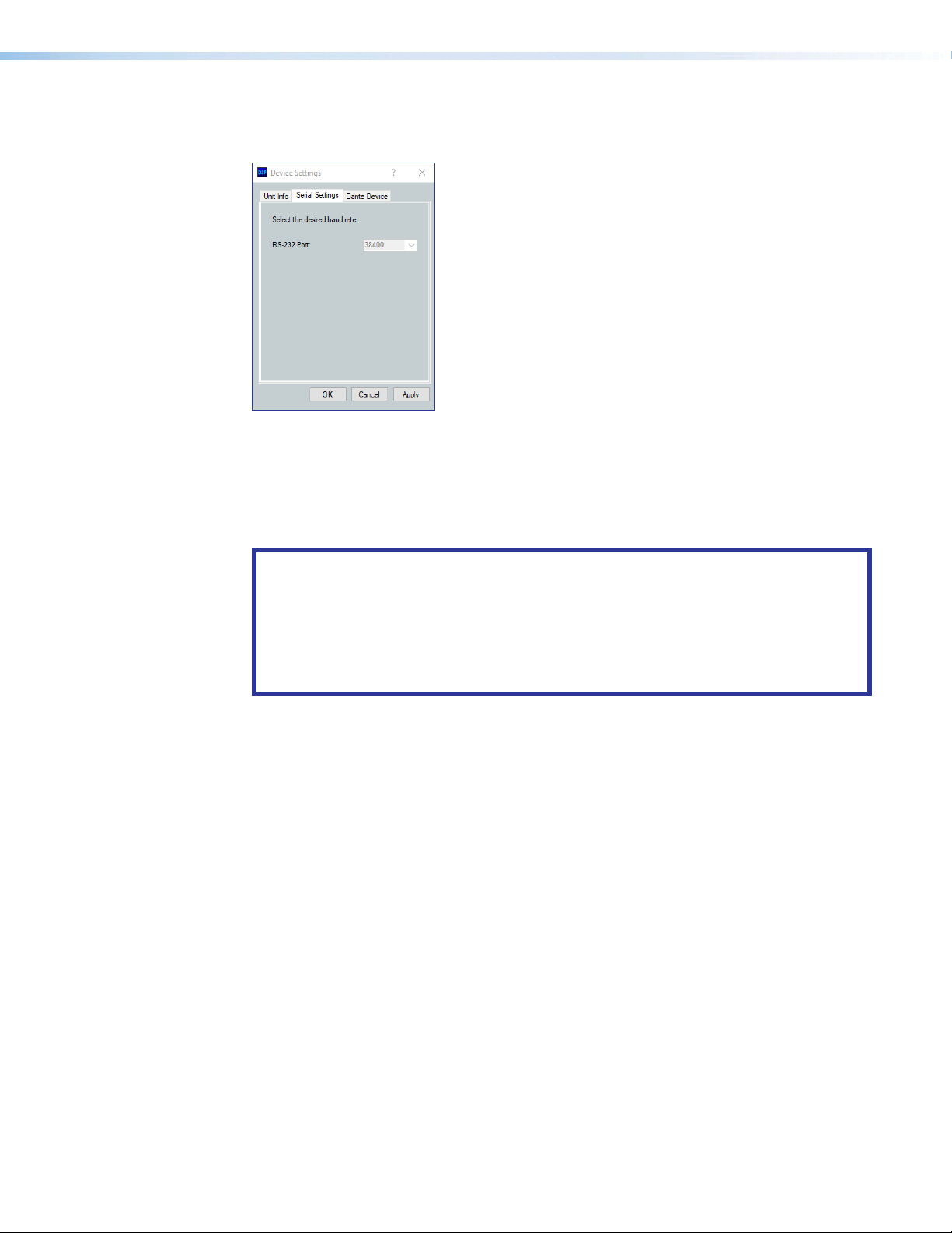
Serial Settings
Dante Device
The Serial Settings tab display the baud rate of the rear panel RS-232 port.
Figure 80. Serial Settings Tab
This tab allows the NetPA U 2002 SB Dante settings to be configured within DSP
configurator without opening Dante Controller.
ATTENTION: It is essential that a Dante device be named immediately after it is
connected to the Dante network and before audio connections with other devices are
established. Existing connections are removed when a device is renamed.
ATTENTION : Il est essentiel qu'un appareil Dante soit nommé immédiatement après
sa connexion au réseau Dante et avant l'établissement de connexions audio avec
d'autres appareils. Les connexions existantes sont supprimées lorsqu'un périphérique
est renommé.
Dante Device Name
A Dante device can be renamed to identify the device on the audio network.
To assign the Dante device name:
1. Select Tools > Device Settings.
2. Use the arrows to navigate to the Dante Device tab.
3. Click the Device name text box.
4. Enter a device name for the Dante interface.
5. Click Apply. A confirmation dialog box opens.
6. Click Yes, to confirm removing existing connections after the name is changed.
NetPA U 2002 SB User Guide • Configurator Tools 73
Page 81

Options
Dante Device Network Settings
To configure Dante network settings:
1. Select the DHCP or Static IP radio buttons. If using DHCP, the NetPA Ultra Series
Dante interface assigns an IP address by the DHCP server and Dante network
configuration is complete. If Static IP is selected, proceed to step 2.
2. Enter a valid network configuration into the respective fields.
3. Click Apply.
To reboot the Dante interface:
• Click Reboot Dante. Only the Dante interface reboots, not the entire unit.
To refresh the device name and network configuration displayed:
• Click Refresh to have DSP Configurator refresh information from the NetPA U 2002 SB
Dante interface.
The Options dialog box allows the user to edit and reset default options for
DSPConfigurator color schemes, default processor and gain block behavior, as well as a
number of other settings.
For a comprehensive overview of the Options dialog box, see the DSP Configurator Help
File.
NetPA U 2002 SB User Guide • Configurator Tools 74
Page 82

Dante Controller
This section describes the NetPA Ultra Series network installation, configuration, and control
using Dante Controller for Windows and covers the following topics:
• Overview
• Downloading and Installing Dante Controller
• Configuring a NetPA U 2002 SB Amplifier in Dante Controller
• Dante Controller Operation
• Routing Devices
• Dante Troubleshooting
Overview
NetPA Ultra Series amplifiers use Dante technology by Audinate to provide high
performance digital audio networking over standard TCP/IP networks. The Dante Controller
software application is used to route audio on the network. Dante allows audio channels
to be transported across a switched Ethernet data network while meeting the quality
requirements of professional audio.
Up to 2 channels can be transmitted from a NetPA U 2002 SB amplifier and up to 2
channels can be received from the Dante network. Audio signals are converted by the
amplifier, processed and routed to the Line/AT Outputs, and transmitted onto the Dante
network. Audinate recommends the Dante audio network be kept separate from other
networks. However, the audio network can be shared with control traffic or unrelated
data traffic. Audio channels can be unicast or multicast to make the best use of available
bandwidth.
The NetPA U 2002 SB amplifier is a receiver and transmitter for audio signals on a Dante
Network. This is possible via a unit AT port. The amplifier can be found anywhere on the
Ethernet network and can be relocated without reconfiguring the unit or the network. Dante
Controller can configure (but is not limited to) Dante channel routing and naming, device
naming, obtaining network and device status, and setting the device IP address.
NOTES:
• The AT port can be set to 44.1 kHz, 48 kHz, 88.2 kHz or 96 kHz, however the
signal going through the DSP is converted to and processed at 48 kHz.
• For applications where the line and Dante outputs may be used independently
during long periods of no amplifier activity, such as when the unit is being used as
both an amplifier and off/on-ramp to the Dante network, the auto-standby timer
must be disabled and the amplifier must not be forced into Standby mode.
NetPA U 2002 SB User Guide • Dante Controller 75
Page 83

Downloading and Installing Dante Controller
Dante Controller from Audinate is required to route transmitters and receivers and can be
used to configure Dante settings and monitor performance. Install Dante Controller on a PC
running Microsoft® Windows® 7 or newer. For full details about computer requirements and
to download the software, see the Dante Controller product page at www.extron.com.
To download Dante Controller:
1. From www.extron.com, hover over the Download tab at the top of the page.
2. From the Featured Software list, select Dante Controller.
3. From the Dante Controller product page, click the blue Download button.
4. Select Run to run the Dante Controller installer. Select Save to save the install file to run
at a later time.
5. If you choose to run the file, follow all prompts. If you saved the file, click the saved file
to begin installation when ready.
The installed Dante Controller program files are saved in:
C:\Program Files (x86)\Audinate\Dante Controller\DanteController.exe.
Configuring a NetPA U 2002 SB Amplifier in Dante Controller
Use a standard Ethernet cable to connect the NetPA U 2002 SB to a Dante network via the
rear panel AT port (see Rear Panel Features on page17) and power the device.
Device Name
Multiple devices on the same Dante network can present difficulty in identifying individual
devices. To avoid confusion and difficulty, ensure the following steps are taken:
• Connect devices to the Dante network one at a time.
• Rename each device before making audio connections in Dante Controller.
• Rename each device with a unique and meaningful identifier.
• Rename each device before the next device is connected to the Dante network.
ATTENTION: It is essential that a Dante device be named before audio subscriptions
with other devices are established. Existing subscriptions are removed when a device
is renamed.
ATTENTION : Il est essentiel qu'un appareil Dante soit nommé avant l'établissement
des abonnements audio avec d'autres appareils. Les abonnements existants sont
supprimés lorsqu'un appareil est renommé.
In Dante Controller, a device can be renamed to identify the device on the audio network.
The default device name of the NetPA Ultra Series consists of the model name, followed by
the last six characters of the Dante interface MAC address (for example, NetPA-U-xxxxxx).
In addition to renaming the device, individual Transmitter (Tx) and Receiver (Rx) channels
can be renamed.
The Dante device name must be set before making any connections to other devices on the
Dante network. Renaming a device after making connections removes existing connections
to and from that device. Refer to Renaming the NetPA U 2002 SB Amplifier in Dante
Controller on page77 for renaming procedure.
NetPA U 2002 SB User Guide • Dante Controller 76
Page 84
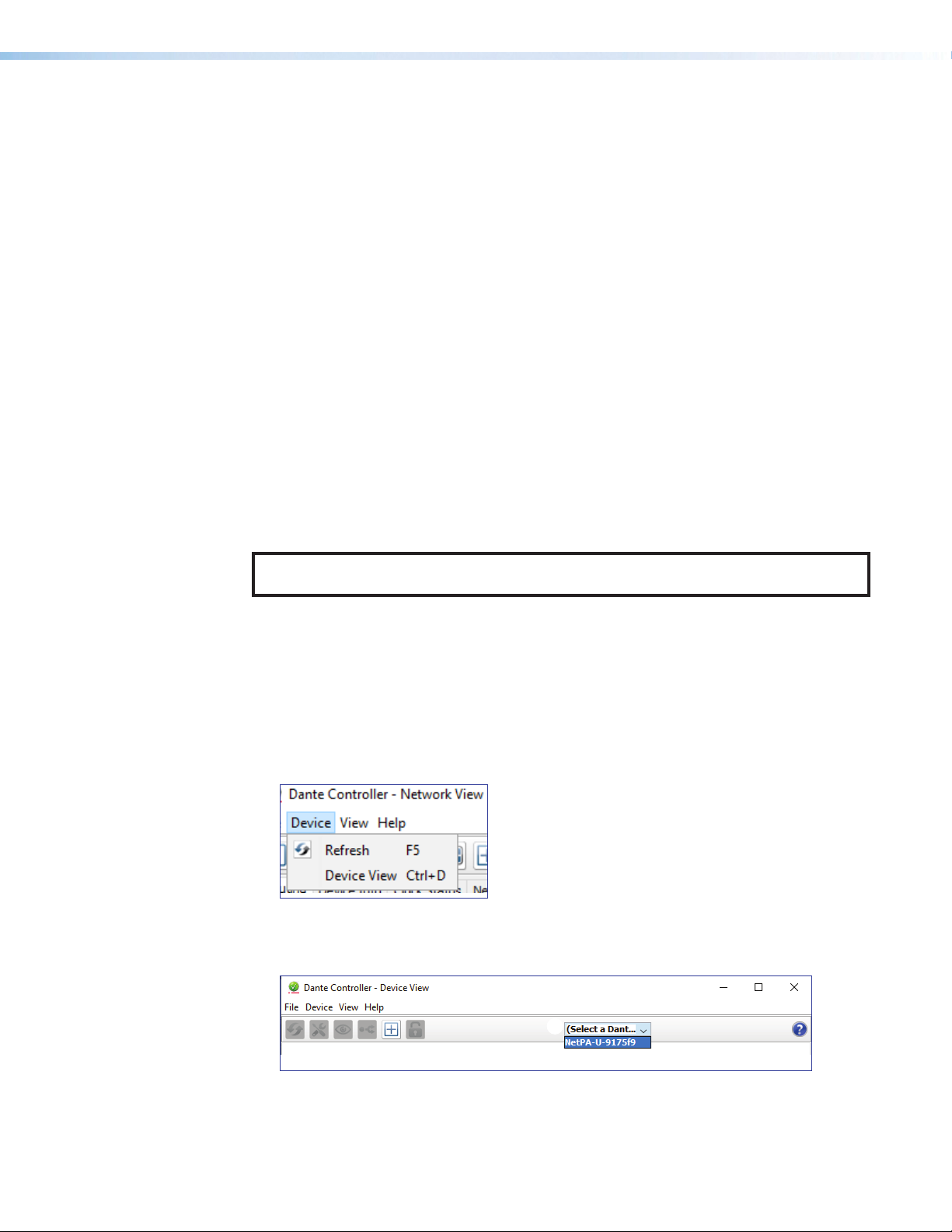
Receiver and Transmitter Names
In addition to renaming a device, individual transmitter and receiver channels can be
renamed in Dante Controller. Rename transmitter and receiver channels to reflect the
location of the device or the purpose of the transmitter or receiver. Ensure transmitter and
receiver channels are renamed before making audio connections between devices. Refer to
Renaming a Receiver or Transmitter on page79 for renaming procedure.
Dante Controller Naming Conventions
• Device names follow Domain Name System (DNS) hostname rules. Legal characters are
A-Z, a-z, 0-9, and hyphen (-). Names must begin with a letter and cannot end with a
hyphen (-).
• Dante Tx and Rx channel names (also known as labels) can be up to 31 characters
in length. Label names are not case-sensitive. For example, “ANALOG OUT-1” and
“analog out-1” are recognized as the same name. Unicode and non-roman
characters are not supported.
• Tx and Rx channel labels can use any character except equals (=), period (.), or @.
• Tx and Rx channel labels must be unique on a device but do not need to be unique on
the network.
Renaming the NetPA U 2002 SB Amplifier in Dante Controller
NOTE: Dante device naming can also be done via DSP Configurator (see Dante Device
on page73).
1. Ensure that the control computer and a single NetPA Ultra Series amplifier is connected
to the same network.
2. From the control computer Start menu select:
All Programs>Audinate>Dante Controller>Dante Controller
3. The Dante Controller - Network View screen opens. All Dante devices on the
network are discovered and listed.
4. From the Device menu, select Device View or press <Ctrl+D> on the keyboard (see
figure 104).
Figure 81. Opening Device View
5. The Dante Controller - Device View dialog opens. Select the device being
configured from the (Select a Dante Device...) drop-down list (see figure82, 1).
1
Figure 82. Device View and Select a Dante Device Drop-Down
NetPA U 2002 SB User Guide • Dante Controller 77
Page 85
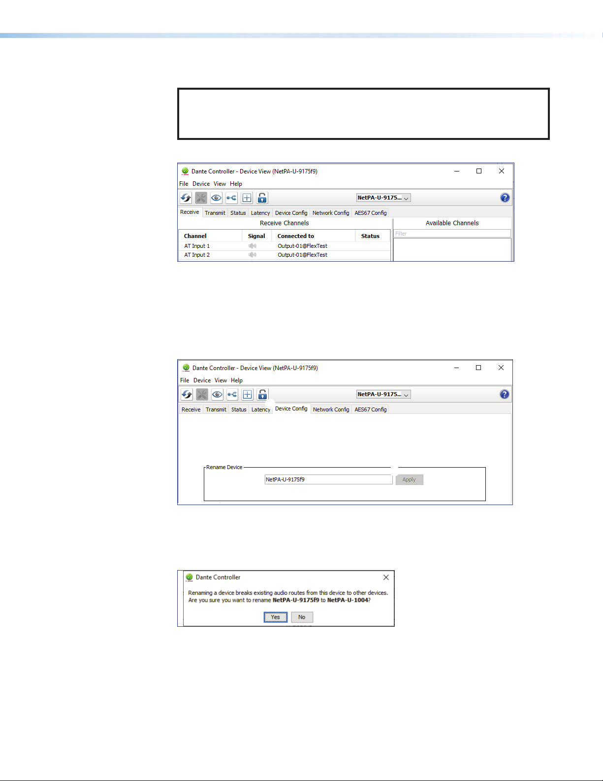
NOTE: If there are multiple NetPA Ultra Series devices connected to the network
that have not been renamed, obtain the Dante interface media access code
(MAC) address of the desired device from the white label on the rear panel of the
device in order to identify it in Dante Controller.
The Device View dialog populates with the selected NetPA Ultra Series information.
Figure 83. Populated Device View Dialog Box
6. Click the Device Config tab (see figure84, 1) to open the Device Config page.
7. In the Rename Device panel, enter the new name of the device in the text field. No
spaces are allowed in the name. Names should be significant identifiers. For example,
enter NetPAUAmplifier-MainRack (2).
8. Click Apply (3). A confirmation prompt opens.
1
2
Figure 84. Device Config Dialog, Rename Device
9. Click Yes (see figure85, 4) to confirm the new name, then close the Device
Configuration dialog box. The new name is written to the Dante interface of the
NetPA Ultra Series amplifier. Repeat as necessary for all devices.
3
4
Figure 85. Rename Device Confirmation Dialog Box
NetPA U 2002 SB User Guide • Dante Controller 78
Page 86
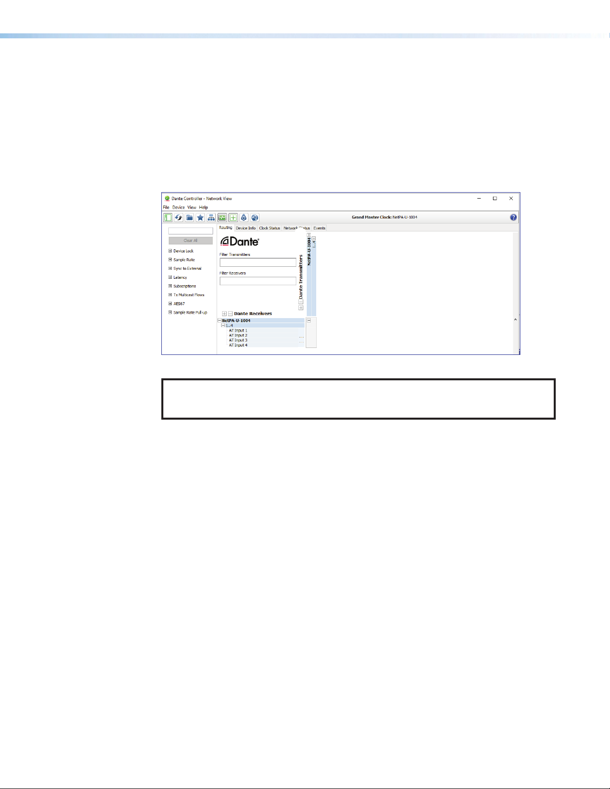
Renaming a Receiver or Transmitter
In addition to renaming devices, individual receiver and transmitter channels can be
renamed in Dante Controller. To better organize the various receivers and transmitters,
it is recommended each receiver and each transmitter be named using a description of
the device they belong to, the location of the device, or the purpose of the receiver or
transmitter.
To view the receiver or transmitter channels in Dante Controller, click the + sign next to the
receiver or transmitter device name to expand it. The + sign becomes a – sign when the
device is expanded (see figure86, 1).
2
1
Figure 86. Expanded Device View — Input and Output Names
TIP: To simplify setup and operation of large matrix systems, rename the receiver and
transmitter channels to better indicate the source at the transmitters or
receivers.
Renaming a Receiver
The default names shown in the Dante Receivers column are extracted from the Dante
interface of the connected device (see figure87, 1, on the next page). The NetPA Ultra
Series receivers are labelled AT Input 1 through AT Input 4. Follow the instructions below
to rename a receiver.
To rename a NetPA Ultra Series receiver:
1. From the Device menu on the Network View screen, select Device View, or press
<Ctrl+D> on the keyboard. The Device View dialog box opens.
2. From the (Select a Dante Device..) drop-down list, select the name of the
desired NetPA Ultra Series amplifier (see figure87, 1, on the next page).
3. On the Device View screen, select the Receive tab (2).
4. Click on the name of the receiver to be renamed. The name becomes a text box with a
cursor (3).
5. Enter the new name (up to 31 characters) using any combination of letters, numbers,
and special characters except for @, =, and . (period).
6. Press <Enter> on the keyboard to confirm the name, or click another channel text box.
7. Repeat steps 4 through 6 to rename additional receiver channels.
8. When finished renaming receivers, close the Device View dialog box.
NetPA U 2002 SB User Guide • Dante Controller 79
Page 87

1
2
3
Figure 87. Device View Screen — Renaming an Amplifier
Renaming a Transmitter
The default names shown in the Dante Transmitters column are extracted from the
Dante interface of the connected device (see figure88, 1, on the next page). The NetPA
Ultra Series receivers are labelled Line Output 1 through Line Output 2. Follow the
instructions below to rename a transmitter.
To rename a NetPA Ultra Series transmitter:
1. From the Device menu on the Network View screen, select Device View, or press
<Ctrl+D> on the keyboard. The Device View dialog box opens.
2. From the (Select a Dante Device..) drop-down menu, select the name of the desired
NetPA Ultra Series amplifier (see figure88, 1, on the next page).
3. On the Device View screen, select the Transmit tab (2).
4. Click on the name of the receiver to be renamed. The name becomes a text box with a
cursor (3).
5. Enter the new name (up to 31 characters) using any combination of letters, numbers,
and special characters except for @, =, and . (period).
6. Press <Enter> on the keyboard to confirm the name, or click another channel text box.
7. Repeat steps 4 through 6 to rename additional receiver channels.
8. When finished renaming receivers, close the Device View dialog box.
Finding a Dante Device IP Address
To find the IP address of a Dante device, the name of the device is needed (see Renaming
the NetPA U 2002 SB Amplifier in Dante Controller on page77).
NOTE: If the NetPA Ultra Series amplifier has not been renamed, its default name
consists of the product name followed by a hyphen, plus the last 6 digits of the device
MAC address (for example, NetPA-U-xxxxxx).
1. Open Dante Controller.
2. On the Dante Controller-Network View screen, click the Device Info tab (see
figure88, 1, on the next page).
On the Device Info page, locate the name of the NetPA Ultra Series in the
Device Name column (2). The IP address is located in the Primary Address
column(3). In the example, the IP address for the connected NetPA Ultra Series is
192.168.254.254.
NetPA U 2002 SB User Guide • Dante Controller 80
Page 88

Figure 88. Device Info Page
Dante Controller Operation
Dante Transmitters and Receivers
A Dante network is comprised of transmitters that output digital audio onto the Dante
network and receivers that receive digital audio input from the Dante network.
• Transmitters output digital audio from the device onto the audio network.
• Receivers take in digital audio from the audio network into the device.
NetPA Ultra Series Transmitters and Receivers
In the NetPA U 2002 SB, the line outputs are independent of Dante outputs. Each output
may be routed independently. The NetPA U 2002 SB has two Dante outputs.
The NetPA U 2002 SB AT input channels are Dante receivers because they receive digital
audio signal from the Dante network that can then be routed and mixed into a mix matrix.
The NetPA U 2002 SB has two Dante inputs.
Dante Routing Operation
Routing Devices
Dante Controller is used for all network signal routing of transmitters and receivers for
Dante-enabled devices. The NetPA U 2002 SB transmitters and receivers are available in
Dante Controller for routing to other Dante devices.
After the NetPA U 2002 SB amplifier is configured, the channels can be routed to the other
Dante devices on the audio network. Channels transmitted to the network or received
from the network are routed using the Dante Controller Routing tab on the Network View
page (see figure89 on the next page). The transmitters, listed horizontally along the top
of the screen, and the receivers, listed vertically down the left side, form a matrix whose
intersections are the connection points between the receivers and transmitters.
• To make a transmitter-to-reciever connection, click once on an intersection.
• To remove a connection, click on the icon at the intersection.
One of the following icons appears at each connection intersection, indicating the status of
both the transmitter and receiver channels and the connections (subscriptions):
NetPA U 2002 SB User Guide • Dante Controller 81
Page 89
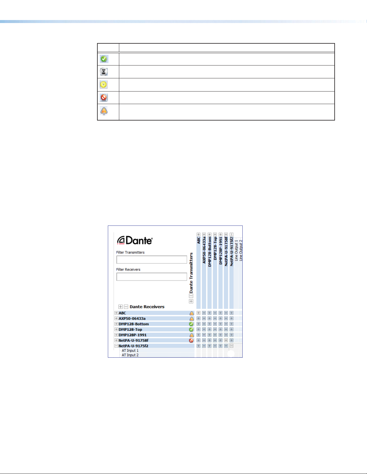
Icon Description
2
3
Indicates an active subscription.
Indicates subscription is in progress.
Indicates a pending subscription.
Indicates a broken subscription.
Indicates the transmitting device has been removed from the network or is
switched off.
See the Dante Controller User Guide, available at www.audinate.com, for additional
information.
Creating Subscriptions Between Devices
1. Ensure the control computer and NetPA Ultra amplifier are connected to the same
network.
2. From the start menu select:
All Programs > Audinate > Dante Controller > Dante Controller
The Dante Controller - Network View screen opens.
Dante Controller auto-discovers Dante devices on the network and advertises itself to
allow other Dante-enabled devices to communicate with it. Transmitters connect to
receivers using the subscription matrix.
1
Figure 89. Routing Tab of Network View Screen
3. To show the transmitters of a Dante device, click the + box next to the desired device in
the Dante Transmitters panel, such as NetPA-U-9175f2 (1). The + changes to
a – sign when the device expands.
4. To show the receivers of a Dante device, click the + box next to the desired device in
the Dante Receivers panel, such as NetPA-U-MainRack (2).
5. Click the intersection of the desired subscription between a transmitter and a
receiver (3).
NetPA U 2002 SB User Guide • Dante Controller 82
Page 90

A check mark at the intersection indicates the subscription is made. A check mark also
appears next to the receiver channel.
NOTE: A receiver can connect to only one transmitter. A transmitter can connect to
multiple receivers.
Disconnecting Inputs from Outputs
To undo routing, click the junction again to disconnect the receiver from the transmitter.
NOTE: After making changes to Dante network routing such as subscriptions, device
names, or channel labels, wait at least 5 seconds before disconnecting or powering
down the devices. This ensures that the new information is properly saved to those
devices. Device level configuration such as sample rates, latency, and clock settings
are saved instantly.
Dante Troubleshooting
The most common Dante troubleshooting issues occur when devices are not discovered by
Dante Controller or when routing is not successful. Both issues occur when software is not
able to properly discover devices operating on the Dante network.
Before moving into more difficult troubleshooting, shut down Dante Controller and reseat the
Ethernet cable connecting the PC to the Dante network and restart Dante Controller. This
can be enough for the software to reacquire the Dante network.
If the problem persists, perform the following troubleshooting procedures in the order listed.
Simplifying the Network for Troubleshooting
If further troubleshooting of Dante Controller is necessary, begin by simplifying the network:
1. Bypass network switches by connecting two Dante-compatible units, such as a
DMP 128 Plus AT and a NetPA U 2002 SB, via their AT ports.
2. Connect the PC to an unused AT port with an Ethernet cable.
3. Use Dante Controller to check if the issue was resolved before moving on to network
interface troubleshooting.
4. If the issue is resolved, add connections and hardware one at a time, checking for
proper operation after each addition, until the point of failure is discovered (typically a
bad cable or invalid redundant configuration).
Troubleshooting the Network Interface
If the issue is still present, continue to diagnose the PC network connections as described
below. Check Dante Controller after each step to see if the problem is resolved.
1. Click the Choose a Dante Interface icon (see figure 90, 1). The Configure Dante
Interfaces dialog box opens.
1
Figure 90. Choose a Dante Interface Icon
NetPA U 2002 SB User Guide • Dante Controller 83
Page 91
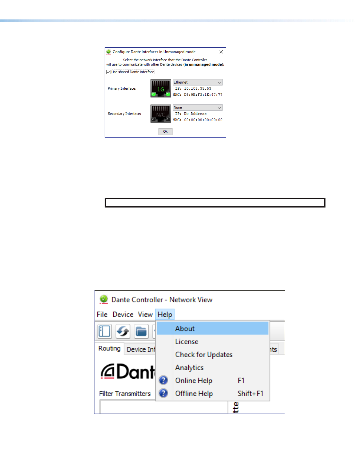
Be certain the correct LAN connection is selected (the PC LAN port that is physically
connected to the AT network) and note the IP address.
Figure 91. Configure Dante Interfaces Dialog Box
2. If it is on, turn off the PC wireless adapter. Disable all connections except the LAN
port connected to the Dante network (verify this is the correct port by checking the IP
address shown in the Configure Dante Interfaces dialog).
3. Turn off all anti-virus and firewall software on the computer.
4. Enable DHCP on the remaining network connection. This forces the computer to
acquire an IP address from the Dante interface.
NOTE: A DHCP server must be on the network for DHCP to function correctly.
Restarting Dante Controller
If subscriptions or normal operation cannot be restored, restart Dante Controller software.
To access the Dante Controller Help File, do any of the following:
• Click the Help icon in the upper-right corner of the Network View screen (see figure
115).
• Select Help, then Online Help or Offline Help from the menu.
• Press the <F1> key on the computer keyboard for online help or <Shift+F1> for offline
help.
Figure 92. Accessing the Dante Help File
NetPA U 2002 SB User Guide • Dante Controller 84
Page 92

Remote Communication and Control
This section describes how to control the NetPA U 2002 SB power amplifier with SIS
commands and covers the following topics:
• Connection Options
• Host-to-Device Communications
• Using the Command and Response Tables
• SIS Commands
• Hardware Reset Modes
• Command and Response Table
• Object ID (OID) Number Tables
• Troubleshooting
Connection Options
The NetPA U 2002 SB can be remotely connected via a host computer or other device
(such as a control system) attached to the rear panel RS-232 port, AT port, or the USB
Config port.
The NetPA U 2002 SB amplifier can be set up and controlled using SIS commands or
DSP Configurator software (see Rear Panel Features on page17 for details on the
configuration and control port connections. For information on DSP Configurator, see
Accessing the DSP Configurator Help File on page27).
SIS Commands can be sent to Dante audio interface devices through a DMP Plus device.
To learn how to do this, visit www.extron.com and read any of the user guides from the
DMP Plus series of matrix processors, such as the DMP 128 Plus.
SIS commands can be executed using the Extron DataViewer application available from
www.extron.com. The host computer issuing the commands can be connected via the
following connections:
• RS-232 Port
• AT Port
• USB Config Port
NetPA U 2002 SB User Guide • Remote Control and Communication 85
Page 93

RS-232 Port
12345678
RJ-45
Connector
Insert Twisted
Pair Wires
Pins:
A cable that is wired as TIA/EIA T568A at one
end and T568B at the other (Tx and Rx pairs
reversed) is a "crossover" cable.
A cable wired the same at both ends is called
a "straight-through" cable because no pin/pair
assignments are swapped.
T568A T568B T568B T568B
Straight-through Cable
(for connection to a switch, hub, or router)
End 1 End 2
Pin Wire Color Pin Wire Color
1 white-orange 1 white-orange
2 orange 2 orange
3 white-green 3 white-green
4 blue 4 blue
5 white-blue 5 white-blue
6 green 6 green
7 white-brown 7 white-brown
8 brown 8 brown
Crossover Cable
(for direct connection to a PC)
End 1 End 2
Pin Wire Color Pin Wire Color
1 white-orange 1 white-green
2 orange 2 green
3 white-green 3 white-orange
4 blue 4 blue
5 white-blue 5 white-blue
6 green 6 orange
7 white-brown 7 white-brown
8 brown 8 brown
The NetPA U 2002 SB has a serial port that can be connected to a host device such as a
computer running either the DataViewer or HyperTerminal utilities. The port makes serial
control of the NetPA Ultra Series possible.
TheNetPA U 2002 SB amplifier uses the following baud rate and protocols:
• 38400 baud • 1 stop bit • 8 data bits • No parity
NOTES:
• The rear panel configuration port requires 38400 baud communication. This
speed is higher than most other Extron products. The NetPA Ultra Series control
software automatically sets the connection for the appropriate speed. When
using DataViewer or similar application, make sure the host PC or control system
is set for 38400 baud.
• See Rear Panel Features on page17 for additional details on connecting to
the RS-232 port.
AT Port
The NetPA U 2002 SB amplifier can be connected to a Dante network. SIS Commands can
be sent to Dante audio interface devices through a DMP Plus device. To learn how to do
this, visit www.extron.com and read any of the user guides from the DMP Plus series of
matrix processors, such as the DMP 128 Plus.
The NetPA Ultra Series amplifier Dante port defaults are as follows:
• DHCP: ON
The Ethernet cable can be terminated as a straight-through cable or a crossover cable and
must be properly terminated for your application.
• Crossover cable — Direct connection between the computer and the NetPA Ultra
Series amplifier.
• Straight-through (Patch) cable — Connection of the NetPA Ultra Series amplifier to
an Ethernet LAN.
Figure 93. RJ-45 Ethernet Connector Pin Assignments
NetPA U 2002 SB User Guide • Remote Control and Communication 86
Page 94

USB Config Port
The NetPA Ultra Series has a rear panel USB port that can be connected to a computer as
a host device running the DataViewer utility for control of the device. Once a connection is
established, SIS programming can begin (see Host-to-Device Communications below).
Verbose Modes
To receive change notices, the session must be in verbose mode 1 or 3 (see Set verbose
mode on page91). In verbose mode 1 or 3, the unit reports changes in messages that
resemble SIS command responses.
Tagged and Untagged Responses
When a query command is sent in verbose mode 0 or 1, only the “untagged” value is
returned. When a query command is sent in other verbose modes, the response is “tagged”
and resembles the response to a set command.
Examle: The gain query command EG40000AU} is sent. The following responses
appear depending on the verbose mode:
• Untagged (verbose 0 or 1): 600], just the gain value with no other information.
• Tagged (verbose 2 or 3): DsG40000*600], the type of query sent, the OID queried,
NOTE: All query responses listed in this guide are untagged.
and the gain value.
Host-to-Device Communications
NetPA U 2002 SB-initiated Messages
The NetPA U 2002 SB initiates messages under specific conditions. No response is required
for the host. The NetPA U 2002 SB-initiated messages are listed below.
Copyright Message
The NetPA U 2002 SB initiates the following copyright message when it is first powered on
or when a USB connection to the NetPA Ultra is made for the first time since the amplifier
powered up.
(c) Copyright 2020, Extron Electronics, {model}, Vn.nn, 60-nnnn-nn]
• Vn.nn is the firmware version number.
• {model} is the full model name, NetPA U 2002 SB, for example.
• 60-nnnn-nn is the NetPA Ultra Series amplifier part number.
The NetPA U 2002 SB amplifier sends the boot and copyright messages under the following
circumstances:
• If the NetPA U 2002 SB is off and RS-232 connection is already set up (the source
PC is cabled to the NetPA Ultra Series and a serial communication program such as
DataViewer is open), the connected unit sends these messages via RS-232 when first
powered on.
• The NetPA U 2002 SB sends the boot and copyright messages when a USB
connection to the NetPA U 2002 SB is made for the first time since the amplifier
powered up.
NetPA U 2002 SB User Guide • Remote Control and Communication 87
Page 95

Using the Command and Response Tables
•
Space
l
I
ASCII to HEX Conversion Table
SIS commands consist of a string (one or more characters per command field). No special
characters are required to begin or end a command sequence. When a NetPA U amplifier
determines a command is valid, it executes the command and sends a response to the host
device. All responses end with a carriage return and a line feed, signaling the end of the
response character string.
When programming, certain characters are more conveniently represented by their
hexadecimal rather than ASCII values. The table below shows the hexadecimal equivalent of
each ASCII character:
Figure 94. ASCII to Hex Conversion Table
The Command and Response tables list valid ASCII commands, the NetPA Ultra Series
responses to the host, and descriptions of the command functions with the results of
executing the commands.
Symbol Definitions
Common Symbol Definitions
]
]
} or ¦
}
E
NOTES:
= CR/LF (carriage return/line feed)
Carriage return with line feed (hex 0D 0A)
=
Carriage return or pipe symbol (no line feed, hex 0D)
=
Carriage return with no line feed (no line feed, hex 0D) (for URL-encoded
=
commands, use the pipe character, | , instead)
=
Escape key, or hex 1B (use W instead of E for web browsers, or at any time)
Pipe (vertical bar) character (URL equivalent to carriage return)
=
|
Space
=
•
Asterisk character (which is a command character, not a variable)
=
*
• Only instances marked with a • character require a space. Any spaces between
characters in the command and response tables are only inserted for ease of
reading.
• Unless stated otherwise, SIS commands are not case sensitive.
NetPA U 2002 SB User Guide • Remote Control and Communication 88
Page 96

Error Responses
When the NetPA U 2002 SB is unable to execute the command, it returns an error response
to the host. The error response codes and their descriptions are as follows:
E10— Unrecognized command E18— System/command timed out
E12— Invalid port number E25— Busy
E13— Invalid parameter E25— Device not present
E14— Not valid for this configuration E30— Hardware Failure (followed by colon
E17— Invalid command for signal type
Hardware Reset Modes
ATTENTION: The reset modes listed below will Close all open IP and Telnet
connections, and Close All Sockets.
and descriptor #)
MODE 1:
MODE 3: To cause an absolute system reset of the Dante module back to factory default conditions:
MODE 5: With power on, press and hold the reset button for about 9 sec. until the Power LED blinks three
Hold the Reset button while applying power to restore the unit firmware back to the default factory
firmware. This recovers a unit that has incorrect code or updated firmware running. All user files and
settings are maintained.
With power on, press and hold the reset button for about 3 sec. until the reset LED blinks one time
(once at 3 seconds), then release and within 1 second press Reset momentarily (< 1 second).
Following this reset, the Dante module will proceed to its normal boot sequence. This reset will:
• Set the IP configuration to default settings
• Clear all Dante channel audio routing
• Set the Dante device name and channel names to default
times (once at 3 sec., again at 6 sec., again at 9 sec.,), then release and within 1 second press Reset
momentarily (<1 sec.).
Mode 5 performs a complete reset to factory defaults, except for firmware:
• Mix-points are set to unity gain (0 dBFS)
• AT input 1 is routed to amp output 1 • AT input 1 is routed to line output 1
• AT input 2 is routed to amp output 2 • AT input 2 is routed to line output 2
• Amp outputs are unmuted and set to -24 dB
• Line and AT outputs are unmuted and set to unity gain
• Trim blocks will be set to unity gain.
• Gain blocks will be unmuted and set to unity gain
• Any inserted or active DSP is removed
• All line inputs are set to unity gain and are unmuted
• All preset and group master memory is cleared
• Status monitoring unsolicited repsonses will be turned off
• Standby timer will be enabled
• Unit will not be in standby
• The output mode will be set to 8Ω stereo
The Reset LED flashes 3 times in quick succession during the reset.
NetPA U 2002 SB User Guide • Remote Control and Communication 89
Page 97

ATTENTION:
• Verify output connector wiring and speaker configuration before resetting the unit
to avoid damage to the speakers and/or amplifier malfunction. Amplifier output
mode after reset is stereo, 8 ohms.
• Vérifiez le câblage du connecteur de sortie et la configuration du haut-parleur
pour éviter les dommages aux haut-parleurs et/ou au dysfonctionnement de
l’amplificateur.
NetPA U 2002 SB User Guide • Remote Control and Communication 90
Page 98
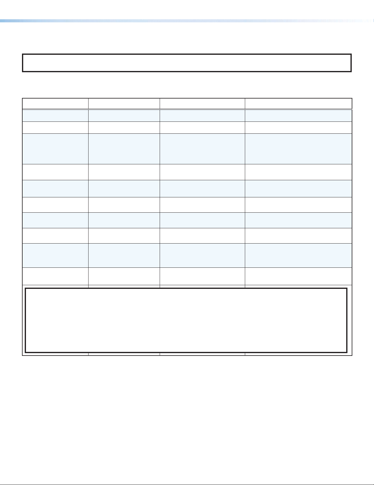
Command and Response Table
NOTE: For commands and examples of computer or device responses used in this guide, the character “0” is the number
zero and “O” is the capital letter “o.”
Generic Hardware Setup and Access
Command ASCII Unit Response Unit Response: Verbose 2/3
Query Part Number
Query Model Number
Query Model
Description
Query Firmware
Version
Query Firmware
Version (w/patch)
N
1I
2I 200•watt•2•Channel•
Q
*Q
60-1757-01]
NetPA•U•2002•SB]
selectable•bridge•
amplier•with•DSP•and•
]
Dante
<version>]
<version>]
Pno 60-1757-01]
Inf01*NetPA•U•2002•SB]
Inf02*200•watt•2•Channel•
selectable•bridge•amplifier•
with•DSP•and•Dante
Ver01*<version>]
Bld*<version>]
]
Query detailed
Firmware Version
Set verbose mode
View verbose mode
Reboot Dante Device
Query Current Status
KEY: Baud Rate: 38400
Device status
X1^
Verbose/Response Mode
X2@
X19(
0Q
X19(]
EX2@CV} VrbX2@]
ECV} X2@]
EBEXPD} ExpdB]
EKEXPD} X1^]
POWERUP = Device is powering up COMM_ERROR = Communication error
POWERDOWN = Device is powering down FIRMWARE_UPGRADING = Firmware is upgrading
READY = Device is ready REBOOT_REQUIRED = Dante device reboot is required
BUSY = Device is busy REBOOTING = Dante device is rebooting
0 = clear 2 = tagged response for queries
1 = verbose mode 3 = verbose mode and tagged responses for queries
<bootloader version> - <factory code version> - <updated code version>
Ver00*X19(]
VrbX2@]
VrbX2@]
Reboot only the Dante interface.
NetPA device remains on during Dante
reboot.
ExpdKX1^]
(verbose 2 and 3 response)
NetPA U 2002 SB User Guide • SIS Command and Response 91
Page 99
Command ASCII Unit Response Unit Response: Verbose 2/3
Network Commands
Set DHCP On
View DHCP status
Set Dante IP/subnet/
gateway
View IP/subnet/
gateway
View MAC address
ED1EXPD} ExpdD1]
EDEXPD} X1%]
EIX#*X$*X%EXPD} ExpdIX#*X$*X%]
EIEXPD} X#*X$*X%]
EHEXPD} X^]
E13 is returned if DHCP is already enabled.
DHCP must be off in order for this
command to be accepted as valid (DHCP
is enabled by default). Dante device reboot
is also required for the command to take
effect.
ExpdDX1%]
(verbose 2 and 3 response)
Using this command automatically turns
DHCP off. Dante device must be rebooted
for new IP configuration to take effect (see
the Reboot Dante device command in the
previous page)
ExpdIX#*X$*X%]
(verbose 2 and 3 response)
ExpdHX^]
View Dante device
name
KEY: Baud Rate: 38400
X#
X$
X%
X^
X&
X1%
IP address
Subnet mask
Gateway IP
MAC address
Dante device name
DHCP status
ENEXPD} X&]
xxx.xxx.xxx.xxx
xxx.xxx.xxx.xxx
xxx.xxx.xxx.xxx
xx-xx-xx-xx-xx-xx
Dante device name Device names follow Domain Name System (DNS) hostname rules. Legal characters are
A-Z, a-z, 0-9, and hyphen (-). Names must begin with a letter and cannot end with a hyphen (-)
1 = enabled (default), 0 = disabled
ExpdNX&]
NetPA U 2002 SB User Guide • SIS Command and Response 92
Page 100
Standby
Command ASCII Unit Response Unit Response: Verbose 2/4
Status Commands
Disable auto-standby
NOTE: Turns off standby mode.
E0PSAV} PsavX12!]
Enable auto standby
(Default)
E1PSAV} PsavX12!]
NOTE: The amplifier enters auto power save mode if there is no active signal for 25 minutes. Whenever this command is sent, the standby timer
restarts and the amplifier goes into power save state.
Force standby on
E2PSAV} PsavX12!]
NOTE: Unit goes into standby and stays in standby until PSAV is set to another mode.
Query standby
EPSAV} X12!*X12@]
PsavX12!*X12@]
power mode,
power save state
NOTES:
• When the amplifier is first powered up, the amplifier will be in Psav1*1.
• Unsolicited responses will be sent out when the unit goes into or out of standby mode.
• Line outputs are disabled when in standby mode.
• Standby power mode should be set to ‘0’ if this amplifier is to be used as an off-ramp.
• Standby Priority:
• The standby contact closure port has the highest priority and supersedes SIS and the timer.
• SIS is the next highest priority and supersedes the timer.
• The timer has the lowest priority and can be overruled by contact closure and/or SIS.
KEY:
X12!
X12@
Mode x SIS Standby power mode
Mode x Power save state
0 = auto standby timer disabled
1 = auto standby timer running, but not triggered (Default)
2 = standby triggered (SIS triggered)
0 = unit is active and auto standby timer disabled
1 = auto standby timer running, but not triggered (Default)
2 = standby triggered (SIS triggered)
3 = standby triggered (timer triggered)
4 = standby triggered (contact closure triggered)
When the standby contact closure is shorted, the unit goes into mode 4 and
cannot come out of mode 4 until the port is no longer shorted. Once the short
is removed the unit returns to its last known standby mode and the timer
resets.
NOTE: Unsolicited responses will be sent out when the unit goes into or out of standby mode.
NetPA U 2002 SB User Guide • SIS Command and Response 93
 Loading...