

Page 1

NAVigator
System Manager
User Guide
Streaming AV Products
68-2740-01 Rev. A
04 21
Page 2

Safety Instructions
Safety Instructions • English
WARNING: This symbol, , when used on the product, is intended to
alert the user of the presence of uninsulated dangerous voltage within
the product’s enclosure that may present a risk of electric shock.
ATTENTION: This symbol, , when used on the product, is intended
to alert the user of important operating and maintenance (servicing)
instructions in the literature provided with the equipment.
For information on safety guidelines, regulatory compliances, EMI/EMF
compatibility, accessibility, and related topics, see the Extron Safety and
Regulatory Compliance Guide, part number 68-290-01, on the Extron website,
www.extron.com.
Sicherheitsanweisungen • Deutsch
WARUNG: Dieses Symbol auf demProdukt soll den Benutzer darauf
aufmerksam machen, dass im Inneren des Gehäuses dieses Produktes
gefährliche Spannungen herrschen, die nicht isoliert sind und die einen
elektrischen Schlag verursachen können.
VORSICHT: Dieses Symbol auf dem Produkt soll dem Benutzer in
der im Lieferumfang enthaltenen Dokumentation besonders wichtige
Hinweise zur Bedienung und Wartung (Instandhaltung) geben.
Instructions de sécurité • Français
AVERTISSEMENT : Ce pictogramme, , lorsqu’il est utilisé sur le
produit, signale à l’utilisateur la présence à l’intérieur du boîtier du
produit d’une tension électrique dangereuse susceptible de provoquer
un choc électrique.
ATTENTION : Ce pictogramme, , lorsqu’il est utilisé sur le produit,
signale à l’utilisateur des instructions d’utilisation ou de maintenance
importantes qui se trouvent dans la documentation fournie avec
l’équipement.
Pour en savoir plus sur les règles de sécurité, la conformité à la réglementation,
la compatibilité EMI/EMF, l’accessibilité, et autres sujets connexes, lisez les
informations de sécurité et de conformité Extron, réf. 68-290-01, sur le site
Extron, www.extron.com.
Istruzioni di sicurezza • Italiano
AVVERTENZA: Il simbolo, , se usato sul prodotto, serve ad avvertire
l’utente della presenza di tensione non isolata pericolosa all’interno
del contenitore del prodotto che può costituire un rischio di scosse
elettriche.
ATTENTZIONE: Il simbolo, , se usato sul prodotto, serve ad avvertire
l’utente della presenza di importanti istruzioni di funzionamento e
manutenzione nella documentazione fornita con l’apparecchio.
Per informazioni su parametri di sicurezza, conformità alle normative,
compatibilità EMI/EMF, accessibilità e argomenti simili, fare riferimento alla Guida
alla conformità normativa e di sicurezza di Extron, cod. articolo 68-290-01, sul
sito web di Extron,
www.extron.com.
Instrukcje bezpieczeństwa • Polska
OSTRZEŻENIE: Ten symbol, , gdy używany na produkt, ma na celu
poinformować użytkownika o obecności izolowanego i niebezpiecznego
napięcia wewnątrz obudowy produktu, który może stanowić zagrożenie
porażenia prądem elektrycznym.
Weitere Informationen über die Sicherheitsrichtlinien, Produkthandhabung,
EMI/EMF-Kompatibilität, Zugänglichkeit und verwandte Themen finden Sie in den
Extron-Richtlinien für Sicherheit und Handhabung (Artikelnummer
68-290-01) auf der Extron-Website, www.extron.com.
Instrucciones de seguridad • Español
ADVERTENCIA: Este símbolo, , cuando se utiliza en el producto, avisa
al usuario de la presencia de voltaje peligroso sin aislar dentro del
producto, lo que puede representar un riesgo de descarga eléctrica.
ATENCIÓN: Este símbolo, , cuando se utiliza en el producto,
avisa al usuario de la presencia de importantes instrucciones de
uso y mantenimiento estas estan incluidas en la documentación
proporcionada con el equipo.
Para obtener información sobre directrices de seguridad, cumplimiento
de normativas, compatibilidad electromagnética, accesibilidad y temas
relacionados, consulte la Guía de cumplimiento de normativas y seguridad de
Extron, referencia 68-290-01, en el sitio Web de Extron, www.extron.com.
UWAGI: Ten symbol, , gdy używany na produkt, jest przeznaczony do
ostrzegania użytkownika ważne operacyjne oraz instrukcje konserwacji
(obsługi) w literaturze, wyposażone w sprzęt.
Informacji na temat wytycznych w sprawie bezpieczeństwa, regulacji wzajemnej
zgodności, zgodność EMI/EMF, dostępności i Tematy pokrewne, zobacz Extron
bezpieczeństwa i regulacyjnego zgodności przewodnik, część numer 68-290-01,
na stronie internetowej Extron,
www.extron.com.
Инструкция по технике безопасности • Русский
ПРЕДУПРЕЖДЕНИЕ: Данный символ, , если указан
на продукте, предупреждает пользователя о наличии
неизолированного опасного напряжения внутри корпуса
продукта, которое может привести к поражению
электрическим током.
ВНИМАНИЕ: Данный символ, , если указан на продукте,
предупреждает пользователя о наличии важных инструкций по
эксплуатации и обслуживанию в руководстве, прилагаемом к
данному оборудованию.
Для получения информации о правилах техники безопасности,
соблюдении нормативных требований, электромагнитной
совместимости (ЭМП/ЭДС), возможности доступа и других вопросах
см. руководство по безопасности и соблюдению нормативных
требований Extron на сайте Extron: , www.extron.com,
номер по каталогу - 68-290-01.
Page 3

安全说明 • 简体中文
警告: 产品上的这个标志意在警告用户, 该产品机壳内有暴露的危险
电 压 ,有 触 电 危 险 。
注意: 产品上的这个标志意在提示用户, 设备随附的用户手册中有重
要的操作和维护(维修)说明。
关于我们产品的安全指南、遵循的规范、EMI/EMF 的兼容性、无障碍使
用的特性等相关内容,
敬请访问 Extron 网站 , www.extron.com,参见 Extron 安全规范指南,产品编号
68-290-01
。
安全記事 • 繁體中文
警告: 若產品上使用此符 號,是為了提醒使 用者,產品機殼內存在未隔離的危
險電壓,可能會導致觸電之風險。
注意 若產品上使用此符號,是為了提醒使用者,設備隨附的用戶手冊中有重
要 的 操 作 和 維 護( 維 修)説 明 。
有關安全性指導方針、法規遵守、EMI/EMF 相容性、存取範圍和相關主題的詳細資訊,
請瀏覽 Extron 網站:www.extron.com,然後參閱《Extron 安全性與法規遵守手
冊》,準則編號 68-290-01。
안전 지침 • 한국어
경고: 이 기호 가 제품에 사용될 경우, 제품의 인클로저 내에 있는
접지되지 않은 위험한 전류로 인해 사용자가 감전될 위험이 있음을
경고합니다.
주의: 이 기호 가 제품에 사용될 경우, 장비와 함께 제공된 책자에 나와
있는 주요 운영 및 유지보수(정비) 지침을 경고합니다.
안전 가이드라인, 규제 준수, EMI/EMF 호환성, 접근성, 그리고 관련 항목에 대한
자세한 내용은 Extron 웹 사이트(www.extron.com)의 Extron 안전 및 규제 준수
안내서, 68-290-01 조항을 참조하십시오.
Copyright
© 2021 Extron. All rights reserved. www.extron.com
Trademarks
All trademarks mentioned in this guide are the properties of their respective owners.
®
The following registered trademarks (
), registered service marks (SM), and trademarks (TM) are the property of RGBSystems, Inc. or Extron (see
the current list of trademarks on the Terms of Use page at www.extron.com):
Registered Trademarks (
®
)
Extron, Cable Cubby, ControlScript, CrossPoint, DTP, eBUS, EDID Manager, EDID Minder, eLink, Flat Field, FlexOS, Glitch Free,
GlobalConfigurator, GlobalScripter, GlobalViewer, Hideaway, HyperLane, IPIntercom, IPLink, KeyMinder, LinkLicense, LockIt, MediaLink,
MediaPort, NAV, NetPA, PlenumVault, PoleVault, PowerCage, PURE3, Quantum, ShareLink, Show Me, SoundField, SpeedMount, SpeedSwitch,
StudioStation, SystemINTEGRATOR, TeamWork, TouchLink, V-Lock, VideoLounge, VN-Matrix, VoiceLift, WallVault, WindoWall, XPA, XTP,
XTPSystems, and ZipClip
(SM)
Registered Service Mark
: S3 Service Support Solutions
Trademarks
(™)
AAP, AFL (Accu-RATEFrameLock), ADSP(Advanced Digital Sync Processing), AVEdge, CableCover, CDRS(ClassD Ripple Suppression),
CodecConnect, DDSP(Digital Display Sync Processing), DMI (DynamicMotionInterpolation), DriverConfigurator, DSPConfigurator,
DSVP(Digital Sync Validation Processing), EQIP, Everlast, FastBite, Flex55, FOX, FOXBOX, IP Intercom HelpDesk, MAAP, MicroDigital,
Opti-Torque, PendantConnect, ProDSP, QS-FPC(QuickSwitch Front Panel Controller), RoomAgent, Scope-Trigger, SIS, SimpleInstructionSet,
Skew-Free, SpeedNav, Triple-Action Switching, True4K, True8K, Vector™ 4K, WebShare, XTRA, and ZipCaddy
Page 4

FCC Class A Notice
This equipment has been tested and found to comply with the limits for a Class A digital
device, pursuant to part15 of the FCC rules. The ClassA limits provide reasonable
protection against harmful interference when the equipment is operated in a commercial
environment. This equipment generates, uses, and can radiate radio frequency energy and,
if not installed and used in accordance with the instruction manual, may cause harmful
interference to radio communications. Operation of this equipment in a residential area is
likely to cause interference. This interference must be corrected at the expense of the user.
NOTE: For more information on safety guidelines, regulatory compliances, EMI/EMF
compatibility, accessibility, and related topics, see the Extron Safety and Regulatory
Compliance Guide on the Extron website.
Conventions Used in this Guide
Notifications
The following notifications are used in this guide:
CAUTION: Risk of minor personal injury.
ATTENTION : Risque de blessuremineure.
ATTENTION:
• Risk of property damage.
• Risque de dommages matériels.
NOTE: A note draws attention to important information.
TIP: A tip provides a suggestion to make working with the application easier.
Software Commands
Commands are written in the fonts shown here:
^AR Merge Scene,,0p1 scene 1,1 ^B 51 ^W^C.0
[01] R 0004 00300 00400 00800 00600 [02] 35 [17] [03]
E X! *X1&* X2)* X2%* X2# CE}
NOTE: For commands and examples of computer or device responses used in this
guide, the character “0” is the number zero and “O” is the capital letter “o.”
Computer responses and directory paths that do not have variables are written in the font
shown here:
Reply from 208.132.180.48: bytes=32 times=2ms TTL=32
C:\Program Files\Extron
Variables are written in slanted form as shown here:
ping xxx.xxx.xxx.xxx —t
SOH R Data STX Command ETB ETX
Selectable items, such as menu names, menu options, buttons, tabs, and field names are
written in the font shown here:
From the File menu, select New.
Click the OK button.
Page 5

Specifications Availability
Product specifications are available on the Extron website, www.extron.com.
Extron Glossary of Terms
A glossary of terms is available at http://www.extron.com/technology/glossary.aspx.
Page 6

Page 7

Contents
Introduction .................................................... 1
About this Guide ...................................................1
About the NAVigator ............................................. 1
About the System ............................................. 2
Features ...............................................................2
Installation and Operation ............................ 4
Rear Panel Connections and Features .................. 4
Connector and Cable Details ............................ 5
Twisted pair cable termination and
recommendations ........................................ 5
Power supply wiring ......................................6
Front Panel Connection and Indicators .................7
Basic Operation .................................................... 8
Configuration and Other Operations .................8
Reset Operations ..............................................8
Performing Mode 4 and 5 Resets .................9
HTML Operation ........................................... 10
Opening the Embedded HTML Pages ................10
HTML Pages Overview ....................................... 12
Endpoints Page .............................................. 13
Ties Page .......................................................14
EDID Page ...................................................... 15
WindoWall Pages ............................................16
Canvas Configuration page .........................16
Presets page ..............................................17
Tools Pages .................................................... 18
Device Tools page ....................................... 18
System Tools page ..................................... 19
Monitoring Page .............................................21
Settings Page ................................................. 22
Creating a NAV System ......................................22
Network Connection Settings ......................... 23
Discover and Assign Encoders and
Decoders .......................................................25
Configure Selected Endpoint
Communication Settings ................................27
Create Ties ..................................................... 29
Detailed Descriptions and Operations
Endpoints Page .............................................. 30
General tab ................................................. 32
Network tab ................................................36
Input tab ..................................................... 38
Output tab .................................................. 39
Scaling Decoder tab ...................................43
Stream tab ..................................................44
USB tab ......................................................46
OSD tab .....................................................47
Device Details pane and proxy
connections ............................................... 49
Ties Page .......................................................51
EDID Page ...................................................... 52
Assign an EDID to an input .........................54
Download an EDID .....................................56
Add a custom EDID .................................... 57
Delete a custom EDID .................................59
Find EDID common timings ........................60
WindoWall Pages ............................................62
Creating a canvas ....................................... 62
Configuring decoders .................................64
Configuring the mullion ...............................66
Creating presets .........................................67
Recalling presets ........................................69
Switching preset inputs ...............................70
Tools Pages .................................................... 71
Device tools page ....................................... 71
Firmware page ............................................ 74
System Tools page ..................................... 77
Monitoring Page .............................................87
Offline Endpoints pane ................................ 88
Conflicted Endpoints pane .......................... 89
IGMP Querier pane ..................................... 90
Control Systems pane ................................90
Alarms pane ...............................................91
Download Logs ..........................................92
Settings Page ................................................. 93
Editing device details ..................................93
Setting date and time ..................................95
................. 30
viiNAVigator System Manager • Contents
Page 8

Network Connection ................................... 99
Changing the Password ..............................99
Loading a LinkLicense ..............................101
Changing the Port Settings ....................... 103
Changing the Advanced Networking
Settings ................................................... 105
About Page ..................................................107
Control System ........................................... 108
Secure Platform Device ....................................108
Toolbelt ............................................................. 108
Global Configurator Plus ................................... 109
Global Scripter..................................................110
SIS Operation ............................................. 111
Host-to-NAVigator Communications ................. 111
NAVigator-Initiated Messages ........................... 111
NAVigator Error Responses ..............................112
Using the Command and Response Tables ...... 112
SIS Command and Response Tables ................ 113
NAVigator to Endpoints Communication
(Encapsulation) ................................................ 118
Troubleshooting ......................................... 119
Alarms .............................................................. 119
Reference Information .............................. 122
Mounting the NAVigator .................................... 122
Tabletop Use ................................................ 122
Mounting kits ................................................ 122
UL Rack-Mounting Guidelines...................122
Download a Firmware or Software Package .....123
Operation with AES67 Audio ............................126
NAVigator System Manager • Contents viii
Page 9

Introduction
NAVigator
• About this Guide
• About the NAVigator
• Features
About this Guide
This guide contains installation, configuration, and operating information for the Extron
NAVigator Pro AV over IP System Manager.
About the NAVigator
The NAVigator (see figure 1) manages, configures, and controls an AV streaming system
consisting of Extron NAV encoders, and decoders (endpoints). The NAVigator also provides
a centralized communication bridge between the control system and the endpoints.
The NAVigator can support up to 16 endpoints as shipped and can be upgraded via
LinkLicenses to support up to 48, 96, or 240 endpoints.
LAN
00 BNAV
LNK
ACT
NAVigator
PC
Control
Network
e
CONFIG
LAN
OOB NAV/PoE
NAV Encoder 1
NAV Encoder 2
AV
NAV Encoder 3
NAV Encoder n
Streaming
Network
Figure 1. Typical NAVigator Application
The NAVigator provides one central web management interface. It expedites the
system deployment process through bulk endpoint configuration, EDID Minder, and ties
management features. In addition, it also makes system management easier through
system tools such as firmware upgrade, backup, and restore.
The NAVigator is housed in a 1-inch high, half-rack width metal enclosure that can be
mounted in any standard 19-inch rack or under furniture with optional mounting kits.
The NAVigator can be powered via Power over Ethernet (PoE) or by an included external
100 VAC to 240 VAC, 50-60 Hz power supply that provides worldwide power compatibility.
NAV Decoder 1
NAV Decoder 2
NAV Decoder 3
NAV Decoder n
NAVigator System Manager • Introduction 1
Page 10

Features
About the System
The NAVigator and NAV endpoints form an AV over IP switching matrix on an Internet Group
Management Protocol (IGMP) Managed IP Network. The managed AV system can stream:
• HDCP 2.3-compliant HDMI video (which can include embedded digital audio) at
resolutions up to 4k@60 Hz and 4:4:4 chroma sampling
• Optional analog audio
• RS-232 and IR control signals
NOTE: The RS-232 and IR communications are only controllable through an Extron
Control Processor via a Secure Platform Device (SPD) (see the Global Configurator
Plus Help File). The encoder and decoder do not generate or respond to the RS-232
and IR communication signals.
The encoders are configured for low latency multicast streaming.
The decoders tie to an encoder.
• Securely manages, configures, and controls NAV Pro AV over IP systems.
• Each unit supports up to 240 NAV endpoints — Offers encrypted management and
control up to 240 NAV endpoints for centralized, secure management of complete Pro
AV over IP systems.
• Intuitive, web-based user interface for ease of use — Intuitive graphical web
interface for configuration, monitoring, backup/restoration, and troubleshooting.
• Manages simultaneous configuration of multiple NAV devices — Enables bulk
configuration of a large number of devices in a single operation, saving time and
simplifying setup.
• Secure encrypted communication between all endpoints — Features secure
communication ensuring any data sent to encoders or decoders from the NAVigator is
encrypted.
• Power over Ethernet, or PoE, eliminates the need for a local power supply —
PoE enables receipt of power directly from the PoE switch, eliminating the need for
bulky local power supplies.
• Scalable with LinkLicense — The base NAVigator system supports 16 devices with
the capability to expand to 48, 96, or 240 with the addition of LinkLicenses.
• Multiple NAVigator systems can work together to support thousands of endpoints,
creating future-ready solutions that grow with your organization.
• Secure network isolation with dual LAN interfaces — Two isolated, independent
LAN ports facilitate control from a secondary network, enabling flexible system design
with enhanced security, and eliminating AV traffic on the corporate network.
• Enables parallel firmware update of multiple NAV devices at once — Upgrades
firmware on all endpoints directly from the NAVigator web interface for quick and reliable
firmware management that enables efficient system enhancements.
• Integrates with Pro Series control systems for secure, user-friendly external
control — Designed to integrate directly with Extron Pro Series control systems for
secure, encrypted RS
additional control processors.
-232 and IR control of external devices without the need for
NAVigator System Manager • Introduction 2
Page 11

• External Extron Everlast power supply included — Provides worldwide power
compatibility with high-demonstrated reliability and low power consumption.
• Extron Everlast Power Supply is covered by a 7-year parts and labor warranty.
• 1-inch (2.5 cm) high, half rack width metal enclosure — Compact, low profile
enclosure for discreet placement and concealment.
NAVigator System Manager • Introduction 3
Page 12

Installation and
BBBCCCAAA DDD
Operation
This section describes the installation and the operation of the NAVigator, including:
• Rear Panel Connections and Features
• Front Panel Connection and Indicators
• Basic Operation
NOTE: For equipment mounting, see Mounting the NAVigator on page 122.
Rear Panel Connections and Features
POWER
12V
0.5 A MAX
Figure 2. NAVigator Rear Panel Connectors and Features
Power connector (optional) — See below.
A
NAV/PoE port — See page 5.
B
OOB (Out of Band) port
C
RESET button and LED
D
Power connector (optional) — Plug the included external 12 VDC power supply into
A
this 2-pole connector for power by a local device.
ATTENTION:
• Do not connect power to the NAVigator until you have read the CAUTION and
ATTENTION notices on pages 6 and 7.
• Ne connectez pas l’alimentation à l’NAVigator avant d’avoir lu les rubriques
« ATTENTION » des pages 6 et 7.
NAVigator
RESET
LAN
OOB NAV/PoE
NOTE: Alternatively, the NAVigator can be powered via PoE, supplied by either an
optional PI 140 Power Injector or a PoE capable network switch.
NAVigator System Manager • Installation and Operation 4
Page 13

NAV/PoE port (see figure 2 on page 4)— Connect this port to your A/V LAN network
Side
Pair Wires
Pins:
B
for control of the NAVigator, control of the A/V streaming network (NAV encoders and
decoders), or both. Optionally, you can also power the NAVigator by inserting PoE
through this port. Streaming endpoints must be on the same network as the
NAV/PoE port.
ATTENTION:
• Power over Ethernet (PoE) is intended for indoor use only. It is to be connected
only to networks or circuits that are not routed to the outside plant or building.
’alimentation via Ethernet (PoE) est destinée à une utilisation en intérieur
•
L
uniquement. Elle doit être connectée seulement à des réseaux ou des circuits
qui ne sont pas routés au réseau ou au bâtiment extérieur.
OOB (Out of Band) port
C
— Connect this port to a network for remote management of
the NAV System. The OOB port cannot receive PoE.
NOTE: The OOB Port should not be connected to the same network as the
NAV/PoE Port.
RESET button and LED — Press this button and observe the LED to initiate three
D
levels of NAVigator reset (see Reset Operations, on page 8).
Connector and Cable Details
Twisted pair cable termination and recommendations
Figure 3 details the TIA/EIA T568-B wiring standard. Use this standard to terminate twisted
pair (TP) cables with RJ-45 connectors.
12345678
Insert
Twisted
RJ-45
Connector
TIA/EIA T 568B
Pin
Wire color
White-orange
1
Orange
2
3
White-green
4
Blue
5
White-blue
Green
6
White-brown
7
Brown
8
Figure 3. TP Cable Termination
NAVigator System Manager • Installation and Operation 5
Page 14
Power supply wiring
Power Supply
Output Cord
SECTION A–A
Ridges
Smooth
AA
Tie Wrap
3
5
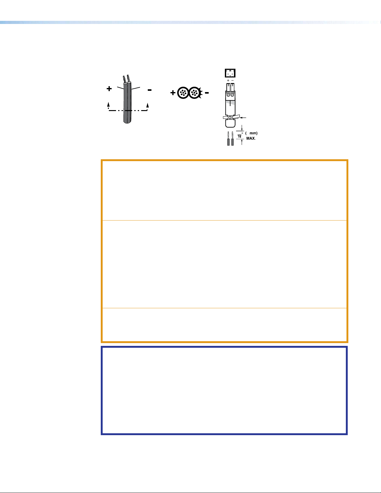
Figure 4 shows how to wire the connector. Use the supplied tie-wrap to strap the power
cord to the extended tail of the connector.
Figure 4. Power Connector Wiring
CAUTION:
ATTENTION :
• The DC output cables must be kept separate from each other while the power
supply is plugged in. Remove power before wiring.
• Les câbles de sortie CC doivent être séparés les uns des autres tant que la
source d’alimentation est branchée. Coupez l’alimentation avant d’effectuer les
raccordements.
The length of exposed wir
•
Any longer and the exposed wir
•
• Any shorter and the wires can be easily pulled out even if tightly fastened by the
captive screws.
La longueur des câbles exposés est
•
(3/16inches).
• S’ils sont un peu plus longs, les câbles exposés pourraient se toucher et
provoquer un court circuit.
•
S’ils sont un peu plus courts, ils pourraient sortir
les vis captives.
• Do not tin the power supply leads before installing them in the connector. Tinned
wires are not as secure in the connector and could be pulled out.
• Ne pas étamer les conducteurs avant de les insérer dans le connecteur. Les câbles
étamés ne sont pas aussi bien fixés dans le connecteur et pourraient être retirés.
es is critical. The ideal length is 3/16 inch (5 mm).
es may touch, causing a short circuit.
primordiale. La longueur idéale est de 5mm
, même s’ils sont attachés par
ATTENTION:
• This product is intended to be supplied by a UL Listed power source marked
“Class 2” or “LPS,” rated 12 VDC, 1.5 A minimum. Always use a power supply
supplied by or specified by Extron. Use of an unauthorized power supply voids all
regulatory compliance certification and may cause damage to the supply and the
end product.
• Ce produit est destiné à une utilisation avec une source d’alimentation listéeUL avec
l’appellation «Classe2» ou «LPS» et normée 12Vcc, 1,5A minimum. Utilisez
toujours une source d’alimentation fournie ou recommandée par Extron. L’utilisation
d’une source d’alimentation non autorisée annule toute conformité réglementaire et
peut endommager la source d’alimentation ainsi que le produit final.
NAVigator System Manager • Installation and Operation 6
Page 15

ATTENTION:
BBBAAA CCC
•
Unless otherwise stated, the AC/DC adapters ar
spaces or in wall cavities.
• Sauf mention contraire, les adaptateurs AC/DC ne sont pas appropriés pour une
utilisation dans les espaces d’aération ou dans les cavités murales.
• The installation must always be in accordance with the applicable provisions of
National Electrical Code ANSI/NFPA 70, article 725 and the Canadian Electrical
Code part 1, section 16. The power supply shall not be permanently fixed to a
building structure or similar structure.
Cette installation doit toujours êtr
•
au National Electrical Code ANSI/NFPA70, article725, et au Canadian Electrical
Code, partie1, section16. La source d’alimentation ne devra pas être fixée de
façon permanente à une structure de bâtiment ou à une structure similaire.
• Power supply voltage polarity is critical. Incorrect voltage polarity can damage the
power supply and the unit. The ridges on the side of the cord (see figure 4 on
page 6) identify the power cord negative lead.
• La polarité de la source d’alimentation est primordiale. Une polarité incorrecte
pourrait endommager la source d’alimentation et l’unité. Les stries sur le côté du
cordon (voir l’illustration 4 sur la page 6) permettent de repérer le pôle négatif du
cordon d’alimentation.
To verify the polarity before connection, plug in the power supply with no load and check the
output with a voltmeter.
e en accord avec les mesures qui s’applique
e not suitable for use in air handling
Front Panel Connection and Indicators
CONFIG
e
Figure 5. NAVigator Front Panel Features
Power LED — Indicates the unit power status.
A
Blinking — The unit is receiving power, either locally or remotely (via PoE) and is
booting up.
Lit — The unit is receiving power, either locally or remotely (via PoE) and is operational.
Configuration port — Connect to this USB mini-B port (USB 2.0) for product
B
configuration, management and firmware updates.
LAN LEDs (OOB and NAV) — Indicate the status of the ports.
C
Link (green) — Indicates the status of the link.
• Blinking — A network link has been established at 10/100 Mbps.
• Lit — A network link has been established at 1 Gbps.
Act (blinking amber) — Network activity is present. The blink rate corresponds to
activity.
LAN
OOBNAV
LNK
ACT
NAVigator
NAVigator System Manager • Installation and Operation 7
Page 16

Basic Operation
Configuration and Other Operations
Reset Operations
Configuration and more complex operation of the system is accomplished via
embedded web pages (see HTML Operation, beginning on page 10); Extron Toolbelt,
Global Configurator Plus, Global Configurator Professional, or Global Scripter (see Control
System on page 108), or SIS commands (see SIS Operation, starting on page 111).
The rear panel RESET button initiates three modes of reset (numbered 1, 4, and 5, using
standard Extron nomenclature; modes 2 and 3 are not applicable to NAV products). The
RESET button is recessed, so use an Extron Tweeker, a pointed stylus, or ballpoint pen to
access it.
See the table on page 9 for a summary of the modes.
ATTENTION:
• Review the reset modes carefully. Using the wrong reset mode may result in
unintended loss of flash memory programming, port reassignment, or a controller
reboot.
• Étudier de près les différents modes de réinitialisation. Appliquer le mauvais mode
de réinitialisation peut causer une perte inattendue de la programmation de la
mémoire flash, une reconfiguration des ports ou une réinitialisation du contrôleur.
NOTE:
• The reset modes listed in the table are separate functions, not a continuation from
mode 1 to mode 5.
• The modes listed close all open IP connections and close all sockets.
•
eset modes 4 and 5, nothing happens if the momentary press does not occur
For r
within 1 second.
NAVigator System Manager • Installation and Operation 8
Page 17

Reset Mode Comparison and Summary
Release, then immediately
press and release again.
RESET
RESET
Release, then immediately
press and release again.
6 seconds
9 seconds
Press and hold
the Reset button.
Press and hold
the Reset button.
Reset LED blinks twice.
Reset LED blinks
three times.
IP Settings
Reset
Factory
Reset
(Mode 4)
(Mode 5)
Mode Activation Result Purpose and
1
Hold down the recessed
applying power to the unit.
NOTE: After a mode 1 reset is
performed, update the unit firmware
to the latest version. Do not operate
the unit firmware version that results
from the mode 1 reset. If you want to
use the factory default firmware, you
must upload that version again (see
Hardware reset
Updating the NAVigator firmware
on page 74 for details on uploading
firmware).
RESET button while
The unit reverts to the factory default firmware. All user files
and settings, such as IP settings, are maintained.
NOTE: If you do not want to update firmware, or you
performed a mode 1 reset by mistake, cycle power to
the unit to return to the firmware version that was running
before the mode 1 reset (see About Page on page 107
to find the firmware version).
Notes
Use mode 1
to return the
unit to the
factory default
firmware version
if incompatibility
issues arise with
user-loaded
firmware.
4
Hold the
6 seconds, until the
(once at 3 seconds and again at 6 seconds).
Then momentarily press
second.
Reset IP settings
5
Hold the
9 seconds, until the
three times (once at 3 seconds, again at 6
seconds, and then again at 9 seconds). Then
momentarily press RESET within 1 second.
Factory reset
RESET button for approximately
RESET LED blinks twice
RESET within 1
RESET button for approximately
RESET LED blinks
NOTE: Reset mode 5 reverts the
factory-configured username to
admin and password to extron.
Performing Mode 4 and 5 Resets
Resets all the IP settings without affecting the device
configuration. Mode 4:
Enables ARP capability.
•
•
Sets the IP address, subnet address, gateway address, and
port mapping to the factory default.
•
Sets the Multicast IP, stream number and device name to the
factory default.
•
Turns DHCP on.
RESET LED blinks three times in succession during the reset.
The
Mode 5 performs a complete reset to factory defaults (with
the exception of the firmware):
•
Does everything mode 4 does.
•
Resets most settings.
•
Resets all IP options.
•
Removes all files from the unit.
RESET LED blinks four times in succession during the reset.
The
Mode 4 enables
you to set
IP address
information using
ARP and the
MAC address.
Mode 5 is for
starting over with
configuration
and uploading
or to replace
events. Same as
the EZQQQ}
SIS command
on page 115.
Perform resets of the unit as follows (see figure 6):
1. Use a small screwdriver to press and hold the rear panel RESET button until the rear
panel RESET LED blinks either:
• Twice, for an IP settings reset
• Three times for an absolute (factory) reset
Figure 6. Resets
2. Release the RESET button and then immediately press and release the RESET button
again. Nothing happens if you do not momentarily press RESET within 1 second.
NAVigator System Manager • Installation and Operation 9
Page 18

HTML Operation
This section introduces using the built-in HTML pages to configure and operate the
NAVigator, including:
• Opening the Embedded HTML Pages
• HTML Pages Overview
• Creating a NAV System
• Detailed Descriptions and Operations
The NAVigator can be controlled and operated through either the front panel CONFIG
(USB) port (see figure 5, A on page 7) or the rear panel NAV/PoE port (see figure 2, B on
page 4) or OOB port (C on page 5). The Configuration port uses IP over USB technology.
The factory-embedded pages are always available and cannot be erased or overwritten.
NOTE: If connection to the NAVigator using either the NAV/PoE port or OOB port is
unstable, try turning off the proxy server in your web browser.
Opening the Embedded HTML Pages
Access the NAVigator using HTML pages as follows:
1. Start the web browser.
NOTES:
• Extron recommends the following browsers to fully support the NAV system:
• Google Chrome™ — All screen images in this guide use Chrome.
Click in the
2.
• Mozilla Firefox™
• Microsoft
The network must be pr
•
so may result in degraded performance.
Address
NOTES:
• For the NAV/PoE+ port, if unit does not receive an IP address from the DHCP
server, it self-assigns a Link Local IP address in the range 169.254.X.X.
• Default settings:
Config (USB)* 203.0.113.22
NAV/PoE (RJ-45)
OOB (RJ-45) Off 192.168.253.254 255.255.255.0
* For the Config port, the address for IP over USB CANNOT be changed.
For the NAV/PoE port, if unit does not receive an IP address from the DHCP
Server, it self-assigns a Link Local IP address in the range 169.254.X.X.
• If you use IP over USB, Extron recommends waiting a minute after plugging in
the cable from your PC to identify the USB connection as a valid Ethernet port.
®
Edge™
operly configured for multicasting (IGMP). Failure to do
field of the browser and enter the IP address.
Port DHCP IP address Subnet mask
On
NAVigator System Manager • HTML Operation 10
Page 19

3. Press the keyboard <Enter> key.
111111111111111111
2222222222
22222222
1111
2222
3333
NOTES:
• If you do not have a trusted SSL Certificate, the browser displays a
privacy notification (see figure 7). Continue to the login dialog box as follows:
Click the br
1.
Advanced [1] in Chrome). Explanatory text and a link appear.
owser button that advances past the privacy notification (such as
Figure 7. Privacy Notification (Shown in Chrome Browser)
2.
Click Proceed to <IP address> (unsafe) (2) (or similar message).
• Your IT department can provide an uploadable SSL Certificate (see
page 108). Once the certificate is loaded, the notification does not occur.
The browser opens to the Login dialog box (see figure 8).
Toolbelt on
1111111111
1111
2222
2222222222
3333333333
3333
Figure 8. Login Dialog Box
4. Enter the Username (see figure 8, 1) and Password (2) and click Sign In (3). The
browser opens the embedded HTML page (see figure 9 on page 12).
NOTES:
• The factory configured passwords for all accounts on this device have been
set to the device serial number. In the event of a complete system reset, the
passwords revert to the default.
• The default username is admin and the default password is extron.
• Passwords are case sensitive.
NAVigator System Manager • HTML Operation 11
Page 20

8888
2222
1111111111
1111
3333
4444
7777
5555
6666
9999
££££
¢¢¢¢
1111
5555
5555555555
6666
6666666666
8888888888
8888
2222
2222222222
3333
3333333333
4444
4444444444
7777
7777777777
NOTES:
• The HTML page may open with any of the panes (items 2 through 7 below)
selected.
•
The login automatically times out after 30 minutes of inactivity
¢¢¢¢¢¢¢¢¢¢
¢¢¢¢
.
9999
9999999999
££££££££££
££££
HTML Pages Overview
See figure 9 and the following sections for an overview of the following panes or functions.
See Creating a NAV System on page 22 for procedures to use items 7, 2, and 3 to
create a NAV system. See Detailed Descriptions and Operations on page 30 for detailed
descriptions of items 4 through 7, and £.
1
2
3
4
5
6
7
8
9
Figure 9. Home Page
Menu icon — Toggles to hide or show the links pane (items 2 through 7).
Endpoints link — Opens a page that allows you to discover and assign endpoints. You
can then view these assigned endpoints and make configuration and communications
settings changes to them (see Endpoints Page on page 13).
Ties link — Opens a page that allows you to make and break ties. See Ties Page on
page 14.
EDID link — Opens a page that allows you to select an EDID and assign it to one or
more inputs (encoders). See EDID Page on page 15.
WindoWall link — Opens pages that allow you to configure NAV WindoWall canvases
and to save, apply, and clear NAV WindoWall presets (see WindoWall Pages on page 16).
Tools link — Opens pages that provide NAVigator tools and tools for entire system,
including the endpoints (see Tools Pages on page 18).
Monitoring link — Opens a page that shows system status information (see
Monitoring Page on page 21).
Settings link — Opens a page that provides access to many NAVigator device settings
(see Settings Page on page 22).
admin menu — Click to display the Sign Out button. Click Sign Out
to log out of the NAVigator HTML pages.
NAVigator System Manager • HTML Operation 12
Page 21

Endpoints Page
2222
1111
2222
1111
1111
1111111111
2222222222
2222
Name banner (see figure 9 on page 12) — Normally displays the host name. Resting
¢
the cursor over this banner changes the display from host name to the device name.
About link — Opens a page that provides information about the NAVigator (see About
£
Page on page 107).
The Endpoints page allows you to discover endpoints and assign one or more to the
NAVigator. To access the Endpoints page, if necessary, click the Menu icon (see figure 10, 1
and figure 11, 1). Click Endpoints (2). The Endpoints page opens. See Creating a NAV
System on page 22 for a detailed description of discovering and assigning endpoints as
part of creating a system.
Figure 10 shows the Endpoints page when no endpoints have been discovered or assigned.
Figure 11 shows the Endpoints page when endpoints have already been discovered and
assigned and are online.
Figure 10. Endpoints Page with no Discovered Endpoints
1111111111
1111
2222222222
2222
Figure 11. Endpoints Page with Discovered and Assigned Endpoints
NAVigator System Manager • HTML Operation 13
Page 22

2222
1111111111
1111
1111
Ties Page
2222222222
2222
The Ties page allows you to make or break ties to create or change the input/output
matrix in a NAV system. To access the Ties page, if necessary, click the Menu icon
(see figure 12, 1). Click Ties (2). The Ties page opens, displaying a grid of endpoints
assigned to this NAVigator and indicates existing ties. See Creating a NAV System on
page 22 for a detailed description of assigning and tying endpoints as part of creating a
system.
Figure 12. Ties Page
NAVigator System Manager • HTML Operation 14
Page 23

EDID Page
2222
1111
1111
1111111111
The EDID page allows you to select an EDID and assign it to one or more inputs (encoders).
To access the EDID page, if necessary, click the Menu icon (see figure 13, 1). Click EDID (2).
The EDID page opens, displaying a library of available EDIDs, favorite EDIDs, and connected
output (display) EDIDs. See EDID Page on page 52 for a detailed description of using
EDIDs.
2222222222
2222
Figure 13. EDID Page
NAVigator System Manager • HTML Operation 15
Page 24

2222
3333
1111
1111111111
1111
2222
5555
4444
3333
6666
7777
1111
WindoWall Pages
The NAVigator can support up to eight NAV WindoWalls with
mixed sources. The NAVigator can support up to eight
workspaces called canvases, each of which can support
up to eight rows by eight columns.
The
WindoWall pages provide tools to configure canvases
and to save, apply, and clear NAV WindoWall presets. To open the NAV WindoWall pages, if
necessary, click the Menu icon (see figure 14, 1). Click WINDOWALL (see 1 in the illustration at
right) and either Canvas Configuration (2) or Presets (3).
Canvas Configuration page
The Canvas Configuration page (see figure 14) provides tools to assign decoders to
NAV WindoWall canvases. See WindoWall pages on page 62 for a detailed description of
using this page and Creating presets on page 67 to create NAV WindoWalls and presets.
2222
2222222222
1111111111
1111
2222222222
2222
3333333333
3333
3333
5555555555
5555
3333333333
4444444444
4444
Figure 14. Canvas Configuration Page
The
Canvas Configuration page consists of the following elements:
Canvas selection tabs — Select a canvas to configure.
2
Canvas View — A grid diagram in which each cell represents a display in the
3
NAV WindoWall and which can include the display number (displays are numbered
horizontally on the canvas view), the decoder, and the total output resolution.
Canvas Configuration — Provide the Canvas ID (for identification to a control system),
4
define the size of the canvas, and assign it a name.
NAVigator System Manager • HTML Operation 16
6666666666
6666
7777
7777777777
Page 25

Output Assignments (see figure 14 on page 16) — Assign decoders to the displays
1111
3333
AAAA
2222
5
in the NAV WindoWall.
Display Settings — Adjust the display settings of all outputs in the canvas.
6
Mullion Compensation (off-screen on figure 14, see figure 66 on page 66) — Adjust
7
the space around displays to extend the image "behind" the bezels of flat panels.
Presets page
The Presets page (see figure 15) allows you to assign encoders (sources) to NAV WindoWall
canvases and to save the canvas as a NAV WindoWall preset. See WindoWall pages on
page 62 for a detailed description of using the Canvas Configuration page and this page
and to create NAV WindoWalls and presets.
1111111111
1111
2222222222
2222
3333333333
3333
AAAA
AAAAAAAAAA
Figure 15. WindoWall Presets Page
See figure 15. The
Canvas selection tabs — Select a canvas to configure.
1
Canvas view — A grid diagram in which each cell represents a display in the NAV
2
Input and preset controls — Assign encoders, manage presets, and switch inputs.
3
Presets page consists of the following elements:
WindoWall.
TIP: Each canvas has a canvas ID (A) that identifies that canvas. If you need to
reference a canvas from a control system, the canvas ID does not change, even if
you have renamed the canvas.
NAVigator System Manager • HTML Operation 17
Page 26

Tools Pages
2222
3333
4444
1111
2222
1111
1111
1111111111
The Tools pages provide tools for just the NAVigator (Device)
and tools for the entire system, including endpoints (System).
To access the Tools pages, if necessary, click the Menu icon
(see figure 16, 1). Click Tools (see 1 in the illustration at
right) and select among:
• Device Tools (2, see "Device Tools page")
• System Tools (3, see System Tools page on page 19)
• Diagnostic Tools (4, see Diagnostic Tools page on page 20).
Device Tools page
The Device Tools page consists of four tabs (2), Backup, Restore, Firmware, and Reset
that provide NAVigator tools. See Device Tools Page on page 71 for detailed descriptions
of these NAVigator tools.
2222222222
2222
1111111111
1111
2222222222
2222
3333333333
3333
4444444444
4444
Figure 16. Device Tools Page
NAVigator System Manager • HTML Operation 18
Page 27

System Tools page
1111
The System Tools page consists of three tabs (see figure 17, 1), Backup, Restore, and
Firmware that provide tools for the NAV system, including all assigned endpoints. See
System Tools Page on page 77 for a detailed description of these system tools.
1111111111
1111
Figure 17. System Tools Page
NAVigator System Manager • HTML Operation 19
Page 28
2222
1111
1111
3333
4444
5555
1111111111
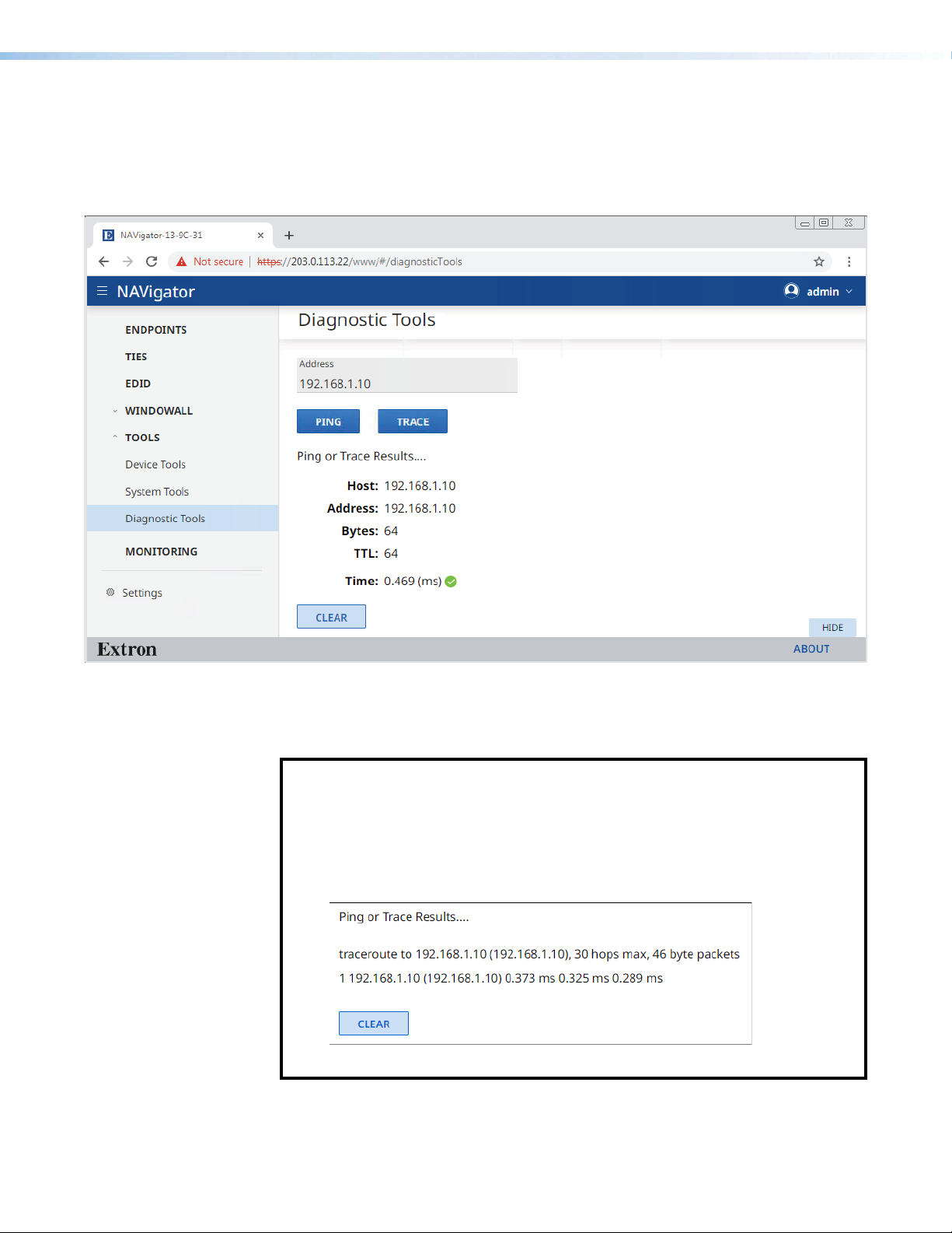
Diagnostic Tools page
The Diagnostic Tools page (see figure 18) provides tools that allow you to troubleshoot the
connection to other units on the NAV network. Access the page as follows:
1. Click the Tools > Diagnostic Tools link on the left side of the browser (1). The
browser displays the Diagnostic Tools page.
2222222222
2222
3333333333
3333
4444444444
4444
5555
5555555555
Figure 18. Diagnostic Tools Page, Ping Results Shown
2. Click in the Address field and type in the IP address of another unit on the network (
3. Click either Ping or Trace (3), depending on the diagnostic you want to run.
NOTES:
• Ping — Use this tool to test the connection to another unit on the network.
Figure 18,
• Trace — Use this tool to trace the network route taken by a packet from
source to destination.
Figure 19 shows the typical results of a Trace diagnostic.
shows the typical results of a Ping diagnostic.
4
2
).
Figure 19. Trace Results Shown
5. Click Clear (5) to reset the Address field if you want to run another diagnostic.
NAVigator System Manager • HTML Operation 20
Page 29

Monitoring Page
111111111111111111
The Monitoring page shows system status information. To access the Monitoring page,
click Monitoring (see figure 20, 1). The Monitoring page opens. See Monitoring Page on
page 87 for a detailed description of the monitored functions.
Figure 20. Monitoring Page
NAVigator System Manager • HTML Operation 21
Page 30

Settings Page
1111
AAAA
BBBB
BBBB
BBBB
BBBB
BBBB
BBBB
The Settings page provides the ability to view and change NAVigator settings. To access
the Settings page, click Settings (see figure 21, 1). The Device Settings page opens.
Using Network Connection (A) is described as part of the procedure to create a NAV system
(see "Creating a NAV System," below).
Using all other selections (B) is described in Settings Page on page 93.
1111111111
1111
AAAAAAAAAA
AAAA
BBBB
BBBBBBBBBB
BBBBBBBBBB
BBBB
BBBB
BBBBBBBBBB
BBBBBBBBBB
BBBB
Figure 21. Device Settings Page
Creating a NAV System
Connection to the NAVigator can be done via the embedded HTML pages. Creating a NAV
system using the NAVigator and its embedded HTML pages is a six-part process:
1.
2.
3.
4.
5.
6. Create and validate ties between the endpoints (see Create Ties on page 29).
7. Construct a control system using either Global Configurator or Global Scripter (see
BBBBBBBBBB
BBBB
BBBB
BBBBBBBBBB
Connect to the NA
Embedded HTML Pages on page 10).
V
iew and change NAVigator network settings as necessary (see Network Connection
Settings on page 23).
Discover and assign endpoints to the NA
Encoders and Decoders on page 25).
V
iew and change endpoint network settings as necessary (see Configure Selected
endpoint communication settings on page 27).
Configur
are established, validate input/output signals via the Device Details pane of the endpoints.
Control System on page 108).
e the AV sources, displays, and other equipment. Once endpoint communication
Vigator via the embedded HTML pages (see Opening the
V system (see Discover and Assign
NAVigator System Manager • HTML Operation 22
Page 31

Network Connection Settings
1111
2222
3333
4444
View and change connection settings as follows:
1. Obtain proper network connection values from the local system administrator.
2. If necessary, click the Menu icon (see figure 22, 1) to toggle the links pane (2) on.
1111111111
1111
2222
2222222222
4444444444
4444
3333333333
3333
Figure 22. Network Connection Page
3. Click
4. Click Network Connections (4). The Network Connections drop-down menu opens,
Settings (
showing protected views of the network connection settings.
). The Device Settings page opens.
3
NAVigator System Manager • HTML Operation 23
Page 32

5. Examine the network connection settings, comparing them against the values provided
4444
2222
2222
3333
1111
1111
by the local system administrator. If all values are correct, proceed to Discover and
Assign Encoders and Decoders on page 25.
6. To change the settings, click the appropriate (OOB - Public LAN or NAV - AV LAN) Edit
button (see figure 23, 1). The Edit button changes to Save and the variable fields
become available for editing.
NOTE: The IP Address, Subnet, Gateway, DNS Server, and DNS Sux fields are
unavailable for editing when DHCP is on.
3333
3333333333
2222222222
2222
4444444444
2222
2222222222
4444
1111111111
1111 1111111111
Figure 23. Device Settings Pane
7. If desired, click the DHCP switch (
and off.
8. If desired, click the Port Enabled switch (3, OOB - Public LAN port only) to toggle the
enable on and off.
9. If desired, click in the desired editable field (4) and edit it as desired.
10. Repeat step 9 as necessary for other values.
11. Click Save (1).
NOTE: If you change the settings of either port, you will lose communications
momentarily while the NAVigator and endpoints self-reconfigure. This is normal.
1111
) to toggle Dynamic Host Configuration Protocol on
2
NAVigator System Manager • HTML Operation 24
Page 33

Discover and Assign Encoders and Decoders
2222
3333
1111
1111
1111
Discover and assign encoders and decoders (endpoints) to the NAV system as follows:
1. If necessary, click the Menu icon (see figure 24, 1).
1111
1111111111
2222222222
2222
3333
3333333333
Figure 24. Discover Endpoints
2. Click Endpoints (
3. Click Discover Endpoints (3). The Assign Endpoints page opens (see figure 26 on
page 26).
NOTE: If you are adding to an existing set of assigned endpoints, at this point the
endpoints page shows the existing endpoints and you click the Discover link
instead (see figure 25, 1).
2
).
11
1111
1111
Figure 25. Appearance of Endpoints Page when Adding to Existing
Endpoints
Continue the discovery and assignment process as described in steps 4 and 5 on
page 26.
NAVigator System Manager • HTML Operation 25
Page 34

2222
2222
2222
2222
3333
3333
BBBB
BBBB
CC
CCCC
CCCC
AAAA
AAAA
1111
1111
CCCC
CCCC
11
1111
1111
22
2222
2222
22
2222
2222
Figure 26. Assign Endpoints
NOTES:
• A banner advises you of how many endpoints you are using and how many for
which you are licensed (see figure 26, A).
• The NAVigator, by default, is licensed for 16 endpoints.
Additional endpoints, up to 240, ar
•
Extron S3 Sales and Technical Support Hotline (see www.extron.com for
the phone number in your region of the world). See Loading a LinkLicense
on page 101 to install the license.
When you assign an endpoint to the NA
•
assumes the password of the NAVigator.
TIPS:
• Use the ID function to help identify an endpoint as follows:
• Press and release the device ID button on the front panel of an endpoint
to highlight the ID field on the HTML page for that endpoint (B). Press and
release the button again to clear the highlight.
• Click the ID field (
the endpoint on and off.
• Tailor the list to more easily find specific endpoints as follows:
Click the Filter drop-down menu (C) to show only endpoints by specific
•
criteria (if created).
Click the Sort drop-down menu to arrange the order in which endpoints are
displayed.
AA
AAAA
AAAA
e available via LinkLicense; contact the
Vigator, the endpoint automatically
) on the HTML page to toggle the front panel ID LED on
B
3333
3333
33
BBBB
BBBB
BB
4. Click the All checkbox (1) or individual endpoint checkboxes (2).
5. Click Assign (3). The NAVigator assigns the
endpoints and reports success on the endpoints
page.
NOTE: Once an endpoint is assigned, it can no longer be discovered by other
NAVigators.
NAVigator System Manager • HTML Operation 26
Page 35

Configure Selected Endpoint Communication Settings
4444
3333
4444
6666
5555
2222
1111
AAAA
BBBB
1111
NOTE: This section configures selected endpoint settings using bulk configuration
(the most convenient approach). See Endpoints page on page 30 for detailed
descriptions of configuring all endpoint settings.
Configure selected endpoint settings in bulk (all at once) as follows:
1. If necessary, click the Menu icon (see figure 27, 1).
1111
1111111111
2222
2222222222
AAAAAAAAAA
3333
3333333333
4444444444
4444
4444444444
4444
Figure 27. Selecting Configure
2. If necessary, click Endpoints (
TIPS: Find specific endpoints more easily as follows:
• Use the ID button and Filter and Sort drop-down menus as described in the
TIPS on page 26.
3. Click the All checkbox (3) or individual endpoint checkboxes (4).
4. Click Actions (5) > Configure (6). The Configure Endpoints page opens (see
5.
6. Click in one or more fields to be edited and make changes as necessary (see
• Click in the
whose name or I/O number contain those characters.
figure 28 and figure 29, both on page 28).
Click the General link (see figure 28, 1) and the Network link (see figure 29, 1) as
necessary to make the desired changes to the settings shown on the figures.
figure 28, 2 on figure 29, 2, both on page 28).
Search field (
AAAA
BBBBBBBBBB
BBBB
). The Endpoints page opens.
2
) and enter a few characters to show endpoints
A
6666
6666666666
5555555555
5555
TIP: Open the HTML page of a single endpoint
for configuration (see Device Details pane and
proxy connections on page 49), as follows:
1. Click in the field for the connected endpoint (see
figure 27, B). The HTML page opens a Device
Details pane at the right of the page.
2. Click the IP Address (
page opens a new tab in the browser that is
connected to the endpoint.
1
, at right). The HTML
NAVigator System Manager • HTML Operation 27
1111111111
1111
Page 36

1111111111
1111
2222
3333
4444
3333
4444
2222
1111
1111
4444
2222
2222222222
Figure 28. Configure Endpoints > General
1111
1111111111
33334444444444
3333333333
4444
2222
2222222222
Figure 29. Configure Endpoints > Network
3. Click Save (
) or Save All (4) on either figure).
3
NAVigator System Manager • HTML Operation 28
3333333333
33334444444444
Page 37

Create Ties
4444
BBBB
AAAA
2222
3333
1111
Create or change a tie in the NAV system as follows:
NOTE: You can also pair encoders and decoders to each other using the endpoint ID
buttons (see the applicable endpoint guides available at www.extron.com).
1111
1111111111
2222222222
2222
If necessary
1.
2. If necessary, click Ties (2). The page displays a grid of inputs and outputs.
AAAAAAAAAA
AAAA
, click the
3333
3333333333
Menu icon (see figure 30,
1
).
Figure 30. Create Ties
NOTE: The tabs (A) select the audio devices that are displayed in the grid. AES67
audio must be enabled to be available (see Operation with AES67 Audio on
3. Click to select the Set Tie Mode (Audio + Video, Audio Only, or Video Only (
4. Click within the grid of inputs and outputs to tie the desired input to the desired decoder
5. If the
page 126).
TIP: Use the browser zoom feature to see more devices in the ties grid.
(or all decoders) (4). Click in an existing tie to untie it.
TIP: Click in an All Decoders box (B) to tie an input to all outputs.
NOTE: In the figure 30 example, Audio + Video from input NAV-E-101-12-F2-41 is
tied to All Decoders (all outputs).
Create Ties page asks you to confirm the change, click Continue.
BBBBBBBBBB
BBBB
4444444444
4444
3
).
NAVigator System Manager • HTML Operation 29
Page 38

Ties are displayed as follows:
2222
1111
4444
4444
4444
4444
3333
AAAA
BBBB
CCCC
6666
DDDD
5555
Detailed Descriptions and Operations
Endpoints Page
Besides the startup tasks of discovering and assigning endpoints to the NAVigator,
the Endpoints pane has tools for “bulk” configuring one or multiple endpoints from the
NAVigator. These tools are a more efficient way to manage your system than making
changes to individual endpoints, either through their HTML pages directly (see the
associated endpoint user guide) or proxied through the NAVigator (see Device Details
pane and proxy connections on page 49).
Access the bulk configuration tools as follows:
1. If necessary, click the Menu icon (see figure 31, 1).
1111
1111111111
Video and audio Video only Audio only
2222222222
2222
AAAAAAAAAA
3333333333
3333
4444
4444444444
4444
4444444444
AAAA BBBBBBBBBB
BBBB CCCCCCCCCC
CCCC
6666666666
6666
DDDD
DDDDDDDDDD
5555
5555555555
4444
4444444444
4444
4444444444
Figure 31. Accessing Bulk Configuration Tools
TIPS: Find specific endpoints more easily as follows:
• Use the ID button and Filter (A) and Sort (B) drop-down menus as described
in the TIPS on page 26.
• Click in the Search field (
whose name or I/O number contain those characters.
• Click Actions>Unassign (
) and enter a few characters to show endpoints
C
) to unassign an endpoint from the NAVigator.
5>A
2. If necessary, click Endpoints (
3. Click the All checkbox (3) or individual endpoint checkboxes (4).
4. Click Actions (5) > Configure (6). The Configure Endpoints tools open (see figure 32
on page 32).
). The Endpoints page opens.
2
NAVigator System Manager • HTML Operation 30
Page 39

NOTE: The procedures that follow assume that you already have the General tab
displayed on the Congure Endpoints tools (see the procedure on page 30).
The bulk configuration tools are located across several panes, accessible by the tabs
identified in the following table. The table lists the panes, the functions available within them,
and provides a link to detailed descriptions of changing those functions.
Tab Configurable function See:
General Name Add and edit names, tags, and locations
on page 33
Input and output
number
Location Add and edit names, tags, and locations
Tags Add and edit names, tags, and locations
Network Communication
Settings
Input HDCP authorized Configure input settings on page 38
Audio format Configure input settings
Output Video output Configure output video and audio
Allow audio only Configure output video and audio
HDCP mode Configure output HDCP settings on
HDCP notification Configure output HDCP settings
Test pattern Output a test pattern on page 42
Scaling Decoder Output resolution Configure the scaler on page 43
Output rate Configure the scaler
Stream Bit rate (Mbps) Configure the streaming settings on
USB (applicable
endpoints only)
OSD On-screen display Configure the OSD on page 47
Aspect ratio Configure the scaler
Auto memory Configure the scaler
Audio mode Configure the streaming settings
AES67 audio address Configure the streaming settings
USB port settings Configure the USB settings on page 46
Screen saver Configure the screen saver on page 48
Edit input and output numbers on page
35
Configure endpoint communication
settings on page 37
settings on page 40
settings
page 41
page 44
NOTES:
• When you make changes on a tab, two buttons become available:
• The Save button for that page (such as for the General tab).
• The Save All button ( ).
• You can make changes on multiple panes and then save them all by clicking .
• You can sort each column by clicking the header row, for example or .
NAVigator System Manager • HTML Operation 31
Page 40

General tab
When the Configure Endpoints tools are opened, they open to the General page (see
figure 32).
NOTE: The General procedures that follow assume that you already have the General
tab displayed on the Configure Endpoints tools (see the procedure on page 30).
Figure 32. Endpoints Page, Configure Tools — General Tab
NAVigator System Manager • HTML Operation 32
Page 41

Add and edit names, tags, and locations
5555
7777
6666
8888
AAAA
3333
4444
2222
1111
You can add a tag to discovered endpoints that are part of a particular usage set. Tags
simplify finding specific endpoints and managing ties. You can add tags to assigned
endpoints, and rename endpoints as desired. You can also associate each endpoint to the
location where it is installed.
TIP: As an example using these features, you can tag all of the encoders associated
with one presenter and one location so that you can limit encoders to that user and
room when making ties.
NOTE: See the NOTES on page 34 for detailed valid character usage rules to ensure
your entries are valid.
Add and edit tags, names, and locations as follows:
, click and drag the horizontal scroll bar (see figure 33, 1) to the right to
Location and Tags fields.
AAAAAAAAAA
AAAA
1.
If necessary
reveal the
NOTE: The Name field is locked in position and does not move.
8888888888
8888
5555555555
6666
5555 7777777777
4444444444
4444
77776666666666
3333
2222
2222222222
1111111111
1111
Figure 33. Add and edit names, tags, and locations
2. To edit a Name or Location, click in the appropriate field and make changes as
necessary (2).
NOTE: Name and Location can also be edited from the Settings > Device Settings
page (see Editing device details on page 93).
3333333333
3. Click anywhere outside the edited field.
NAVigator System Manager • HTML Operation 33
Page 42

4. To create a tag for an individual assigned endpoint, click Add (see figure 33, 3
1111
on page 33). An editable field opens (see figure 34).
1111111111
1111
Figure 34. Creating a Tag
5.
Click in the tag field and make changes as necessary (see figur
anywhere outside the tag field, the tag appears (
6. To create a tag for all endpoints, click in the
as necessary (see figure 33, 4 on page 33).
When you click anywhere outside the
the Add and Remove buttons appear (shown at right).
7. Click Add . The tag appears for each endpoint ( ).
NOTES:
• Cr
eated tags cannot be edited.
Delete a tag by clicking the .
•
• An endpoint can have a maximum of 10 tags.
8.
Click anywher
TIP: An asterisk (A) appears in the tab to indicate that there are unsaved changes.
9. Click Save General (
them.
Click X (8) to close the Configuration Endpoints page or select a different tab or
10.
perform other operations to change other settings.
See the following NOTES for the text rules that apply to tags, names, and locations.
NOTES:
• Special characters, as used in the table below, are as follows:
! ~ ` @ # $ % ^ & * ( ) _ + = { } [ ] |\ : ; “ ‘ < > , . ? and / .
A hyphen (–) is not a special character.
• Tags, names, and locations each have a 63-character limit.
e outside the edited field or fields. The
) or Save All (6) to save the changes or Cancel (7) to abandon
5
Edit All Tags field,
Edit All Tags field and make changes
Save buttons become available.
e 34, 1). When you click
).
Tag Rules Name Rules Location Rules
• Cannot contain special
characters.
• Cannot begin or end
with a hyphen.
• Cannot begin with a
space.
• Spaces are allowed
after the first
character.
• Multiple tags are
allowed, making
filtering and sorting
searching easier.
• Must begin with a letter.
• Cannot contain special
characters.
• Cannot end with a
hyphen.
• Spaces are not allowed.
NAVigator System Manager • HTML Operation 34
• Must begin with a letter.
• Cannot contain special
characters.
• Cannot end with a
hyphen.
• Hyphens are allowed
in any other position.
• Cannot begin with a
space.
• Spaces are allowed
after the first character.
Page 43

2222
4444
3333
3333
5555
1111
AAAA
BBBB
Edit input and output numbers
By default, input and output numbers are assigned by the endpoints. Being generated by an
algorithm, the numbers appear random. If desired, change them as follows:
Click in the desir
1.
or to increment or decrement the field value. The valid range is from 1 to 4096.
NOTE: Each input requires a unique number and each output requires a unique
number.
TIPS:
• Extron recommends sequential I/O numbering across the NAV system.
If you sequentially number inputs and outputs, the NA
•
similar to a traditional Extron matrix switcher.
BBBBBBBBBB
BBBB
Input or Output field (see figure 35,
ed
) and edit it as desired or click
1
V system function is
5555555555
5555
2222222222
2222 4444444444
44443333333333
AAAAAAAAAA
AAAA
A1
A2
A3
1111
1111111111
Figure 35. Edit input and output numbers
TIP: If you enter a value in either the Edit All Inputs or Edit All Outputs field
(A), the first endpoint listed below the edited field is changed to that number (A1).
Subsequent input or output numbers (A2 and A3) increment as the endpoints are
listed from top to bottom.
NAVigator System Manager • HTML Operation 35
Page 44

5555
7777
6666
6666
8888
4444
AAAA
BBBB
BBBB
BBBB
4444
BBBB
3333
2222
1111
CCCC
2. Click anywhere outside the edited field or fields. The Save buttons become available.
TIP: An asterisk (B) appears in the tab to indicate that there are unsaved changes.
Click Save General (2) or Save All (3) to save the changes or Cancel (7) to abandon
3.
them.
4. Click X (see figure 35, 4 on page 35) to close the Configuration Endpoints page or
select a different tab or perform other operations to change other settings.
Network tab
NOTE: The Network procedures that follow assume that you already have the General
tab displayed on the Configure Endpoints tools (see the procedure on page 30).
CCCCCCCCCC
CCCC
1111111111
1111
5555555555
5555 7777777777
8888
8888888888
77776666666666
2222222222
2222
AAAAAAAAAA
AAAA BBBBBBBBBB
BBBB
3333333333
3333
A1
BBBB
BBBBBBBBBB
A2
4444
4444444444
A3
Figure 36. Endpoints Page, Configure Tools — Network Tab
BBBBBBBBBB
BBBB
4444444444
4444
BBBB
BBBBBBBBBB
NAVigator System Manager • HTML Operation 36
Page 45

Configure endpoint communication settings
TIP: Adhere to IP addressing best practices and considerations for IP addressing
schemes in a larger system.
1. Click the Network tab (see figure 36, 1 on page 36) to make changes to the network
settings.
2. If desired, click either the Static or DHCP radio button to choose the desired IP
addressing method.
• You can select either for all inputs (
• You can select either radio button for all inputs (
individual endpoints (3).
• All of the other settings for an endpoint under this tab are unavailable for selection
when that endpoint is selected for DHCP.
3. Click in one or more fields to be edited and make changes as necessary (4).
TIPS:
• If you enter a value in the Edit All IP Addresses field (A), the first endpoint
listed below the edited field is changed to that number (A1).
The IP addresses for subsequent endpoints (A2 and A3) increment as the
endpoints are listed from top to bottom unless you have also made a change
to an individual endpoint (4).
• If you enter a value in either the Edit All Subnets, Edit All Gateways, or Edit
All DNS field (
made a change to an individual endpoint (4).
), all listed endpoints have that value unless you have also
B
) or one or more individual endpoints (3).
2
) and then change the setting for
2
4. Click anywhere outside the edited field or fields. The Save buttons become available.
TIP: After you make any change in steps 2 and 3, an asterisk (C) appears in the
tab to indicate that there are unsaved changes.
5. Click Save Network (5) or Save All (6) to save the changes or Cancel (7) to abandon
them.
6. Click X (8) to close the Configuration Endpoints page or select a different tab to
change other settings.
NAVigator System Manager • HTML Operation 37
Page 46

6666
8888
7777
7777
9999
5555
4444
3333
2222
1111
AAAA
Input tab
NOTE: The Input procedures that follow assume that you already have the General tab
displayed on the Configure Endpoints tools (see the procedure on page 30).
9999
9999999999
AAAAAAAAAA
AAAA
1111
1111111111
6666666666
6666 8888888888
2222222222
4444
4444444444
2222
3333333333
3333
88887777777777
5555555555
5555
Figure 37. Endpoints Page, Configure Tools — Input Tab
Configure input settings
1. Click the Input tab (see figure 37, 1) to make changes to the endpoint settings.
Click the Audio Format drop-down menu for all inputs (2) or for one or more individual
2.
endpoints (3) to select between Auto Detect, HDMI, or Analog.
3. If desired, select (click) or deselect the HDCP Authorized checkbox for all inputs (
for one or more individual endpoints (5).
NOTE: When HDCP Authorized is enabled (checked), the encoder informs the
connected source that it can accept HDCP signals and is HDCP compliant. When
disabled, the encoder informs the connected source that it is not HDCP compliant.
• For sources requiring encryption, enable HDCP Authorized. If HDCP Authorized
is disabled for sources requiring encryption (for example, a Blu-ray player), the
output is muted or a warning message is displayed.
• Some sources may encrypt their output even if the source material does not
require HDCP encryption, preventing content from being displayed on a nonHDCP compliant display. Disable HDCP Authorized to allow the output of the
scaler to remain unencrypted.
TIP: After you make any change in steps 2 and 3, an asterisk (
tab to indicate that there are unsaved changes.
) appears in the
A
4
) or
4. Click Save Input (
5. Click X (
change other settings.
) to close the Configuration Endpoints page or select a different tab to
9
) or Save All (7) to save the changes or Cancel (8) to abandon them.
6
NAVigator System Manager • HTML Operation 38
Page 47

Output tab
NOTE: The Output procedures that follow assume that you already have the General
tab displayed on the Configure Endpoints tools (see the procedure on page 30).
Figure 38. Endpoints Page, Configure Tools — Output Tab
NAVigator System Manager • HTML Operation 39
Page 48

Configure output video and audio settings
6666
7777
7777
8888
3333
2222
5555
4444
1111
AAAA
Configure the video and audio output as follows:
1. Click the Output tab (see figure 39, 1).
AAAAAAAAAA
AAAA
1111
1111111111
7777
7777777777
2222
2222222222
3333333333
3333
8888888888
8888
6666666666
6666 7777777777
4444
4444444444
5555555555
5555
7777
Figure 39. Configure Video and Audio Output Settings
2.
Click the Video Output drop-down menu for all outputs (2)
or for one or more individual endpoints (3) to select among
the available video output formats (shown at right). Auto (if
selected) follows the input format.
NOTE: The decoders change their color space, chroma
3. If desired, select (click) or deselect the Allow Audio Only
sampling and quantization parameters for compatibility
with HDMI and DVI sink devices.
checkbox for all outputs (4) or for one or more individual
endpoints (5).
NOTE: When Allow Audio Only is enabled (checked), and
if an active video input signal is not present in the stream,
the decoder sends a black burst signal to the attached
display. The black burst prevents the display from going
into standby state, allowing the display speakers to play
audio. When Allow Audio ONLY is disabled, the display
goes into standby state if an active video input signal is
not present regardless of whether active audio is.
TIP: After you make any change in steps 2 and 3, an
asterisk (A) appears in the tab to indicate that there are
unsaved changes.
4. Click Save Output (6) or Save All (7) to save the changes or Cancel (8) to abandon them.
5. Click X (9) to close the Configuration Endpoints page or select a different tab to
change other settings.
NAVigator System Manager • Troubleshooting 40
Page 49

Configure output HDCP settings
7777
8888
9999
4444
3333
6666
5555
1111
2222
AAAA
Configure the output HDCP settings as follows:
1. Click the Output tab (see figure 40, 1).
AAAAAAAA
AA
11111111
11
88888888
77
7777777788
99
99999999
33333333
33
44
44444444
22222222
22
Figure 40. Configure Output HDCP Settings
2. If necessary, click and drag the horizontal scroll bar (2) to the right to reveal the HDCP
fields.
NOTE: The Name field is locked in position and does not move.
Click the HDCP Mode drop-down menu for all outputs (3) or for one or more individual
3.
endpoints (4) to select between Follow Input and Always Encrypt.
NOTE: Follow Input mimics the HDCP encryption state of the connected source.
Alway Encrypt maintains the HDCP encrypted state with the output sink device to
improve system switching performance.
55555555
55
66
66666666
4. If desired, select (click) or deselect the HDCP Notification checkbox for all outputs (
or for one or more individual endpoints (6).
5
)
NOTE: When HDCP Notification is enabled (checked) and the source video is
HDCP encrypted but the display attached to the decoder is not HDCP compliant,
the decoder outputs a green screen. When HDCP Notification is disabled, a the
decoder does not output a green screen, but outputs a black screen instead.
TIP: After you make any change in steps 3 and 4, an asterisk (
tab to indicate that there are unsaved changes.
5. Click Save Output (7) or Save All (8) to save the changes or Cancel (9) to abandon them.
6. Click X (¢) to close the Configuration Endpoints page or select a different tab to
change other settings.
) appears in the
A
NAVigator System Manager • HTML Operation 41
Page 50

Output a test pattern
5555
7777
6666
8888
4444
3333
1111
2222
AAAA
Configure the output test pattern as follows:
1. Click the Output tab (see figure 41, 1).
1111
1111111111
6666666666
6666
AAAA
AAAAAAAAAA
3333
3333333333
4444444444
4444
5555555555
5555
8888888888
8888
7777
7777777777
2222
2222222222
Figure 41. Configure Test Pattern
2. If necessary, click and drag the horizontal scroll bar (2) to the right to reveal the Test
Pattern drop-down menu.
NOTE: The Name field is locked in position and does not move.
3. Click the Test Pattern drop-down menu for all outputs (3) or for
one or more individual endpoints (4) to select among the available
test patterns (shown at right) or no test pattern (Disabled).
NOTE: Test patterns are for debug and setup purposes. They
let you validate a video signal path in the system and setup
the displays connected to the outputs.
• Encoders can output color bar and grayscale test patterns.
• Decoders can output color bar, grayscale, alternating
pixels, aspect crop lines, and crosshatch test patterns.
TIP: After you make a change in step 3, an asterisk (
appears in the tab to indicate that there are unsaved changes.
4. Click Save Output (5) or Save All (6) to save the changes or Cancel (7) to abandon
them.
5. Click X (8) to close the Configuration Endpoints page or select a different tab to
change other settings.
A
)
NAVigator System Manager • HTML Operation 42
Page 51

Scaling Decoder tab
££££
¢¢¢¢
¥¥¥¥
¤¤¤¤
5555
4444
3333
2222
7777
6666
9999
8888
1111
AAAA
NOTE: The Scaling procedures that follow assume that you already have the General
tab displayed on the Configure Endpoints tools (see the procedure on page 30).
Configure the scaler
Configure the output scaler settings as follows:
1. Click the Scaling Decoder tab (see figure 42, 1).
AAAAAAAAAA
AAAA
1111
1111111111
££££££££££
££££ ¢¢¢¢¢¢¢¢¢¢
¢¢¢¢
¥¥¥¥¥¥¥¥¥¥
¥¥¥¥
¤¤¤¤
¤¤¤¤¤¤¤¤¤¤
2222
2222222222
3333333333
3333
Figure 42. Endpoints Page, Configure Tools — Scaling Decoder Tab
2. Click the Output Resolution drop-down menu for all outputs (
individual endpoints (3) to select among Follow Input (no scaling) or scaled to a
desired output resolution from the options presented.
3. Click the Output Rate drop-down menu for all outputs (4) or for one or more individual
endpoints (5) to select among the available rates.
NOTE: See the applicable decoder user guide, available at www.extron.com, for a
detailed list of available output resolutions and rates.
4. Click the Aspect Ratio drop-down menu for all outputs (6) or for one or more individual
endpoints (7) to select between Follow (no scaling, maintain the aspect ratio of the
input video) or Fill (scale the output to fill the connected display).
5. If desired, select (click) or deselect the Auto Memory checkbox for all outputs (8) or
for one or more individual endpoints (9). Auto memory automatically saves picture
adjustments to memory based on the incoming signal resolution and recalls them when
the resolution is detected.
4444
4444444444
5555
5555555555
6666
6666666666
7777777777
7777
8888
8888888888
9999999999
9999
) or for one or more
2
TIP: After you make any changes in step 2 through 5, an asterisk (A) appears in
the tab to indicate that there are unsaved changes.
6. Click Save Scaling Decoder (¢) or Save All (£) to save the changes or Cancel (¤) to
abandon them.
NAVigator System Manager • HTML Operation 43
Page 52

7. Click X (¥) to close the Configuration Endpoints page or select a different tab to
¢¢¢¢
9999
5555
4444
3333
2222
5555
3333
8888
5555
5555
7777
6666
7777
7777
7777
3333
BBBB
AAAA
1111
CCCC
££££
¤¤¤¤
change other settings.
Stream tab
Configure the streaming settings
NOTE: Lay out the complete scheme for all streaming IP addressing before adjusting
the addresses to avoid creating a situation in which the system becomes inoperable.
Configure the streaming settings as follows:
1. Click the Stream tab (see figure 43, 1).
CCCCCCCCCC
CCCC
1111
1111111111
¢¢¢¢¢¢¢¢¢¢
¢¢¢¢ 9999999999
9999
¤¤¤¤¤¤¤¤¤¤
¤¤¤¤
££££££££££
££££
2222
2222222222
4444444444
4444
6666666666
6666
BBBB
BBBBBBBBBB
AAAAAAAAAA
AAAA
Figure 43. Endpoints Page, Configure Tools — Stream Tab
2. Click in the Bitrate field for all encoders (
and edit it as desired or click or to increment or decrement the field value. The
valid range is from 150 to 9500.
3333333333
3333
3333333333
3333 8888888888
3333
3333333333
5555555555
5555
5555555555
5555
5555555555
5555
5555
5555555555
7777777777
7777
7777777777
7777
7777
7777777777
7777
7777777777
) or for one or more individual encoders (3)
2
B1
8888
B2
NAVigator System Manager • HTML Operation 44
Page 53

NOTE: The upper limit for 1G encoders is 900 Mbps. The upper limit for 10G
encoders is 9500 Mbps. If you enter a Bitrate value for all encoders (2), it affects
both 1G and 10G products.
3. Click the NAV Audio checkbox or all encoders (figure 43, 4 on page 44) or for one or
more individual endpoints (5) to toggle NAV Audio on and off.
4. Click the AES67 checkbox for all encoders (6) or for one or more individual endpoints
(7) to toggle AES67 audio on and off.
5. Click one or more IP address fields to be edited and make changes as necessary (8).
• AES67 Audio Address fields
• Video IP fields
• Audio IP fields
• USB IP fields (the field is present only for endpoints with USB streaming capabilities)
NOTES:
• Drag the scroll bar (A) as necessary to reveal fields on the right side of the
screen. The right side of the Stream tab is revealed (see figure 44).
Figure 44. Revealed Fields
6. Click anywhere outside the edited field or fields. The Save buttons become available.
7. Click Save Stream (
8. Click X (¤) to close the Configuration Endpoints page or select a different tab to
• The valid range for AES67 Audio Address fields is from 239.69.0.0 to
239.69.255.255.
• The valid range for all other addresses on this pane is from 224.0.0.0 to
239.255.255.255, exclusive of 239.69 addresses, which are reserved for AES67.
• Each field with an address must be unique.
TIPS:
• If you enter a value in the Edit All IPs field for a column of address (such
as AES67 Audio Address (B), the first endpoint listed below the edited field is
changed to that number (B1). Subsequent AES67 Audio Address numbers (B2
and B3) increment as the endpoints are listed from top to bottom unless you
have also made a change to an individual endpoint (8).
• After you make any changes in step 2 through 5, an asterisk (C) appears in the
tab to indicate that there are unsaved changes.
) or Save All (¢) to save the changes or Cancel (£) to abandon
9
them.
change other settings.
NAVigator System Manager • HTML Operation 45
Page 54

USB tab
9999
8888
5555
4444
3333
2222
5555
3333
7777
6666
7777
1111
AAAA
¢¢¢¢
££££
NOTE: The USB tab is present only if you select one or more endpoints with USB
streaming capabilities in Configure Selected Endpoint Communication Settings,
step 3 on page 27.
Configure the USB settings
Configure the USB streaming capabilities of applicable endpoints as follows:
1. Click the USB tab (see figure 45, 1).
AAAAAAAAAA
AAAA
1111
1111111111
££££££££££
££££
9999999999
9999 8888888888
2222222222
2222
3333
3333333333
4444
4444444444
5555555555
5555
6666
6666666666
7777
7777777777
8888
¢¢¢¢¢¢¢¢¢¢
¢¢¢¢
5555555555
3333
3333333333
Figure 45. Endpoints Page, Configure Tools — USB Tab
2. Click the USB Port checkbox for all endpoints (see figure 45,
individual endpoints (3) to toggle the port enabled and disabled.
3. Click the Mode drop-down menu for all endpoints (
endpoints (5) to select between Host and Device.
4. Click the Device Class Filtering drop-down menu for all inputs (
more individual endpoints (7) to select between USB 2.0, or HID Only (Human Interface
Device), a class of devices for human interface such as keyboards and mice.
5555
7777777777
7777
) or for one or more
2
) or for one or more individual
4
6
) or for one or
NOTES:
• The Mode and Device Class Filtering drop-down menus are unavailable for
selection if the USB port is disabled in step 2.
• Device Class Filtering restricts the USB device types, typically for security
purposes. Different functionality applies in the two modes.
NAVigator System Manager • HTML Operation 46
Page 55

TIP: After you make any changes in step 2 through 4, an asterisk appears in the
7777
6666
5555
4444
3333
2222
5555
3333
1111
AAAA
8888
9999
tab to indicate that there are unsaved changes.
5. Click Save USB (see figure 45, 8 on page 46) or Save All (9) to save the changes or
Cancel (
6. Click X (£) to close the Configuration Endpoints page or select a different tab to
change other settings.
OSD tab
Configure the On-screen display and screen saver capabilities of the endpoints as follows:
1. Click the OSD tab (see figure 46, 1).
2. For OSD settings, see "Configure the OSD," below.
For screen saver settings, see Configure the screen saver on page 48.
Configure the OSD
) to abandon them.
¢
1111111111
1111
AAAAAAAAAA
AAAA
9999999999
9999
7777777777
7777 6666666666
2222222222
2222
4444
4444444444
6666
8888888888
8888
) or for one or more individual
2
3333333333
3333
5555
5555555555
3333
3333333333
5555
5555555555
Figure 46. Endpoints Page, Configure Tools — OSD Tab and Operations
3. Click the OSD Type drop-down menu for all endpoints (
endpoints (3) to select between Input OSD (input connection details), status OSD
(general endpoint details), or Disabled (no OSD).
4. Click in the OSD Duration field for all endpoints (4) or for one or more individual
endpoints (5) and edit it as desired or click or to increment or decrement the field
value. The valid range is from 1 to 500 (in seconds) or 501 (always on).
NAVigator System Manager • HTML Operation 47
Page 56

TIP: After you make any changes in step 2 and 3, an asterisk (A) appears in the
8888
7777
6666
5555
6666
4444
3333
4444
2222
1111
2222
1111
AAAA
9999
¢¢¢¢
tab to indicate that there are unsaved changes.
5. Click Save OSD (see figure 46, 6 on page 47) or Save All (7) to save the changes or
Cancel (
6. Click X (9) to close the Configuration Endpoints page, select a different tab to change
other settings, or continue to "Configure the screen saver".
Configure the screen saver
) to abandon them.
8
1111111111
1111
AAAAAAAAAA
AAAA
¢¢¢¢¢¢¢¢¢¢
¢¢¢¢
8888888888
8888 7777777777
3333
1111
1111111111
2222
2222222222
3333333333
4444444444
4444
7777
5555
5555555555
6666666666
6666
9999999999
9999
6666
6666666666
) or for one or
1
2222
2222222222
4444
4444444444
Figure 47. Endpoints Page, Configure Tools — OSD Tab Screen Saver Operations
1. Click the Screen Saver Mute checkbox for all endpoints (figure 47,
more individual endpoints (2) to toggle the port enabled and disabled. This control sets
whether a display immediately enters low power mode screen saver (is muted) upon
loss of sync or displays selected screen (see Screen Saver Image, 5 or 6) for a period
of time set by the Screen Saver Duration setting (3 or 4).
2. Click in the Screen Saver Duration field for all endpoints (3) or for one or more
individual endpoints (4) and edit it as desired or click or to increment or
decrement the field value. This control determines how long the screen saver stays
active, before muting sync to a display. The valid range is from 1 to 500 (in seconds) or
501 (always on).
When Screen Saver Mute is unchecked, the duration automatically becomes 501.
After the duration expires, the encoder drops the active sync, allowing the display to
turn off or enter low power mode.
NAVigator System Manager • HTML Operation 48
Page 57

3. Click the Screen Saver Image setting drop-down menu for all endpoints (see
2222
1111
Endpoints page
Ties page
figure 47, 5) or for one or more individual endpoints (6) to select among:
• Black Screen • Default Image (Extron) (Extron logo)
• Blue Screen • Custom Image (an image of your choosing)
• Retain Last Frame
NOTE: To be available for selection, the custom image must be manually uploaded
into the endpoint (see the applicable User Guide at www.extron.com).
4. Click Save OSD (7) or Save All (8) to save the changes or Cancel (9) to abandon them.
5. Click X (¢) to close the Configuration Endpoints page or select a different tab to
change other settings.
Device Details pane and proxy connections
A Device Details pane for an individual connected endpoint is available from the Ties page
and from the Endpoints page that provides details about that endpoint.
To open the pane, click in the field for the connected endpoint on the
figure 48, 1) or Ties page (2). The HTML page opens a Device Details pane to the right
of the page (see figure 49 on page 50).
Endpoints page (see
11
11111111
22
22222222
Figure 48. Open an HTML Page for a Connected Endpoint
NAVigator System Manager • HTML Operation 49
Page 58

1111
BBBB
AAAA
1111
BBBB
AAAA
Encoder Device Details Decoder Device Details
1111111111
1111
1111
1111111111
AAAA
AAAAAAAAAA
BBBBBBBBBB
BBBB
Figure 49. Device Details Panes
AAAA
AAAAAAAAAA
BBBBBBBBBB
BBBB
TIPS:
Proxy connection
The HTML pages of an endpoint can be opened from the Device Details pane for
additional configuration of that endpoint (known as “proxying an endpoint”).
Click the IP Address link in the Device Details pane (see figure 49, 1). The HTML page
opens a new tab in the browser that is connected to the endpoint. The HTML page for
the endpoint behaves as described in the user guides for the endpoint (see the applicable
encoder and decoder guides available at www.extron.com).
• Tags, if created, are displayed on this pane (A).
• Click Break (
tie.
), if present (if this endpoint is part of a tie), to break the active
B
NAVigator System Manager • HTML Operation 50
Page 59

Ties Page
FFFF
HHHH
BBBB
AAAA
CCCC
DDDD
EEEE
GGGG
Creating ties using the Ties page tools is fully described in Create Ties on page 29.
You can also create ties using an Extron product that can be controlled by the Extron
Digital Signal Processor (DSP) program, such as a DMP 128 Digital Matrix Processor (see
Operation with AES67 Audio on page 126).
AAAAAAAAAA
AAAA
BBBBBBBBBB
BBBB
CCCC DDDDDDDDDD
CCCCCCCCCC
DDDD
EEEE GGGGGGGGGG
EEEEEEEEEE
FFFFFFFFFF
FFFF
HHHH
HHHHHHHHHH
Figure 50. Ties Pane Features
V and AES67 (audio) Tabs — Select the desired tab to display only encoders
NA
A
streaming
NOTE: AES67 audio must be enabled (see Operation with AES67 Audio).
NAV audio, and only encoders streaming AES67 audio.
GGGG
Filter
B
Sear
C
Sear
D
Break button — Unties any established ties when you click in a tie within the grid (
E
Break All Ties button — Breaks all ties in the NAV system.
G
menu (see figure 50) — Click the drop-down menu to show only endpoints by
specific criteria (if created).
ch Inputs field — Click in the field and enter a few characters to search for an
input by name.
ch Outputs field — Click in the field and enter a few characters to search for an
output by name.
NOTE: See Add and edit names, tags, and locations on page 33 to assign and
edit A, B, and C values.
NAVigator System Manager • HTML Operation 51
F
).
Page 60

1111
EDID Page
BBBB
AAAA
EEEE
FFFF
CCCC
DDDD
TIP: You can also open the HTML page of a single
endpoint for configuration (see Device Details pane
and proxy connections on page 49), as follows:
1. Click in the field for the connected endpoint (see
figure 50 H on page 51). The HTML page opens a
Device Details pane at the right of the Ties page.
1111111111
2.
Click the IP Address (1, at right). The HTML page
opens a new tab in the browser that is connected to
the endpoint.
The EDID page (see figure 51) has several tools to tailor the grid to more easily find specific
EDIDs.
1111
AAAA
AAAAAAAAAA
BBBBBBBBBB
BBBB
EEEEEEEEEE
EEEE FFFFFFFFFF
Figure 51. EDID Tools
Search EDIDs — Enter a few characters in a resolution (such as "204" or "216" for
A
2048 x 2160) or refresh rate (such as such as "6" for 60Hz) to search for EDIDs of only
that resolution or rate.
Available EDIDs — Click to show all EDIDs.
B
Favorites — Click show only the EDIDs that you have designated as a favorite (see E
C
and F on page 53).
Connected Outputs — Click to display only the EDIDs of connected output displays
D
(loop-through for the encoder and output for the decoder).
CCCCCCCCCC
CCCC DDDDDDDDDD
DDDD
FFFF
NAVigator System Manager • HTML Operation 52
Page 61

NOTES:
• Available EDIDs — All EDIDs on the NAVigator including custom or uploaded
EDIDs
•
Favorite EDIDs
•
Connected Outputs
Loop through or the Decoder HDMI output.
Set Favorite icon (see figure 51 on page 52)— The EDID is not designated as a
E
favorite. Click the icon in an EDID to toggle the favorite status of that EDID on.
Favorite icon — The EDID is designated as a favorite. Click the icon in an EDID to
F
toggle the favorite status of that EDID off.
— EDIDs that you have tagged as favorite (F).
— Sink devices connected on either the Encoder HDMI
NAVigator System Manager • HTML Operation 53
Page 62

Assign an EDID to an input
2222
3333
1111
Use the EDID page to select an EDID and assign it to one or more inputs (encoders) as
follows:
1. If necessary, click the Menu icon (see figure 52, 1).
1111
1111111111
2222222222
2222
3333333333
Figure 52. EDID Pane
2. If necessary, click EDID (
select and then assign to one or more inputs (encoders).
3. Select the desired EDID (click the , 3). The selected EDID displays in the EDID field
(see figure 53, 1 on page 55). Available input sources are also displayed (2).
). The EDID page displays a library of EDID files which you can
2
3333
NAVigator System Manager • HTML Operation 54
Page 63

1111
AAAA
2222
3333
1111
2222
AAAA
BBBB
CCCC
1111111111
1111
AAAAAAAAAA
AAAA
2222222222
2222
3333
3333333333
Figure 53. EDID Page With EDID Selected
4. Select one or more desired Input Sources (click the , see figure 54,
sources display in the Input Sources field (see figure 53, 1).
NOTE: Click Select All (see figure 54, A) to select all inputs with one click.
). The selected
3
AA
AAAAAAAA BB
Figure 54. EDID Page with Input Sources Selected
TIPS:
• Click the EDID (A) to clear all selections. The page appears as in figure 52
on page 54.
• Click a selected Input Source
• Click Remove All
figure 54.
5. Click Assign EDID (see figure 54,
The NAVigator assigns the EDIDs and reports
success on the EDID page.
) to remove all input selections. The page appears as in
(C
).
2
11
11111111
CC
CCCCCCCC
) to remove that input selection.
(B
22222222
22
BBBBBBBB
NAVigator System Manager • HTML Operation 55
Page 64

Download an EDID
2222
3333
4444
5555
6666
1111
Use the EDID page to download EDID from the library to your PC as follows:
1. If necessary, click the Menu icon (see figure 55, 1).
1111111111
1111
4444444444
4444
5555
2222222222
2222
5555555555
3333
3333333333
6666666666
6666
Figure 55. EDID Pane — Download an EDID
2. If necessary, click EDID (2).
For the EDID to download, click the Information ( ) icon (3).
The HTML page opens an EDID Summary pane to the right of the EDID page (4). The
panel lists:
• Product name • Manufacturer ID • Video format
• Audio type • Native resolution • Maximum resolution
• Max. pixel clock • Maximum character rate • Colorspace and sampling
• Color bit depth •
3. Click
Download EDID (
Chrome browser (6).
High Dynamic Range (HDR)
). Figure 55 shows the results of downloaded EDID in the
5
• 3D
NAVigator System Manager • HTML Operation 56
Page 65

Add a custom EDID
2222
3333
1111
Use the EDID page to add a custom EDID from your PC to the library as follows:
1. If necessary, click the Menu icon (see figure 56, 1).
1111
1111111111
2222222222
2222
3333333333
3333
Figure 56. EDID Page — Add a Custom EDID
2. If necessary, click EDID (
3. Click Add Custom EDID to Library (3). An Open dialog box opens (see figure 57 on
page 58).
2
).
NAVigator System Manager • HTML Operation 57
Page 66

2222
1111
1111
1111
1111111111
Figure 57. Open Dialog Box
2222222222
2222
4. Navigate to the folder where the EDID file is saved (see figure 57,
5. Click
Open
(2). The NAVigator reports that it is
Uploading
NOTE: This action happens quickly; you may not
see it.
The EDID page returns to the top. The added EDID is displayed with a lighter border
color (see figure 58, 1).
Figure 58. Custom EDID Displayed in EDID Page
and then Adding the EDID to the library.
1111111111
1111
). Select the file.
1
NAVigator System Manager • HTML Operation 58
Page 67

2222
3333
5555
4444
1111
1111
1111111111
2222222222
2222
Delete a custom EDID
Use the EDID page to remove a custom EDID as follows:
1. If necessary, click the Menu icon (see figure 59, 1).
4444444444
4444
5555
5555555555
3333333333
3333
Figure 59. Deleting a Custom EDID
2. If necessary, click EDID (
3. Click the Information ( ) icon (3) on the custom EDID you want to remove. The HTML
page opens an EDID Summary pane to the right (4).
NOTE: Factory-installed EDIDs cannot be removed.
TIP: Custom EDIDs are displayed with a lighter border color.
4. Click Remove EDID (
to confirm the deletion.
5. Click Remove. The NAVigator deletes the EDID
and reports success on the endpoints page.
5
). The EDID page displays a library of EDID files.
2
).The HTML page asks you
NAVigator System Manager • HTML Operation 59
Page 68

Find EDID common timings
2222
3333
4444
1111
The find EDID common timings function helps avoid a source device attached to a NAV
encoder from sending a resolution and refresh rate that is beyond the capabilities of some
displays in the system. Such an error would result in a black screen on displays whose
performance capabilities have been exceeded.
Use the EDID page to find common timings as follows:
1. If necessary, click the Menu icon (see figure 60, 1).
1111
1111111111
2222222222
2222
3333333333
3333
4444
4444444444
Figure 60. EDID Pane and Common Timings
2. If necessary, click EDID (
3. Click Connected Outputs (3). If two or more connected outputs are detected, the Find
Common Timings button appears (
4. Click Find Common Timings (4). The page shows a list of connected outputs and timings
that are common to them (see figure 62 on page 61). The page also recommends the
highest resolution and refresh rate compatible with all selected displays (3).
). The EDID page displays a library of EDID files.
2
).
4
NAVigator System Manager • HTML Operation 60
Page 69

NOTES:
CCCCCCCCCCCCCCCCCC CCCCCCCCCCCCCCCCCC
DDDD
AAAAAAAAAAAAAAAAAA
BBBB
EEEE
3333
5555
4444
4444
4444
4444
1111
2222
2222
2222
•
EDIDs fr
Figure 61. EDID Banners
om Extron products are indicated in blue (see figure 61, A).
DDDDDDDDDD
DDDD
BBBBBBBBBB
BBBB
EEEE
EEEEEEEEEE
•
EDIDs fr
• The pale blue numbers (C) indicate the endpoint from which the connected
output EDID (Display EDID) came.
•
•
1111111111
1111
2222
2222222222
2222222222
2222
2222222222
2222
om the products of other companies are indicated in gray (B).
An encoder has (Loop-Thru) (D) in the EDID banner and the number in the
pale blue background (C) is the input number.
A decoder has (Output) (E) in the EDID banner and the number in the pale
blue background (C) is the output number.
5555
5555555555
3333333333
3333
4444444444
4444
4444444444
4444
4444
4444444444
4444444444
4444
Figure 62. Selecting the Common Timing
5. Click the checkbox to select all Connected Outputs (see figure 62,
individual checkboxes (2) to select one or more connected outputs.
6. Select the recommended Common Timing (3) or another available common timing (4).
7. Click Show EDIDs (5). Only the available EDIDs that match the resolution and refresh rate
of the Common Timing selection appear (see figure 63 on page 62).
) or use the
1
NAVigator System Manager • HTML Operation 61
Page 70

2222
1111
Figure 63. Display of Common Timings
8.
Assign the desir
beginning at step 3 on page 54).
TIP: Click Clear Common Timings (A) to clear the list.
ed EDID to one of more encoders (see Assign an EDID to an input,
WindoWall Pages
Creating a video wall is a multi-step process consisting of the following procedures:
NOTE: The list below presents a logical flow of operations; many of these operations
can be performed in any order.
• Create a canvas (see "Creating a canvas," below).
• Configure all decoders in the canvas (see Configuring decoders on page 64).
• Configure the mullion, the space around each display within the canvas (see
Configuring the mullion on page 66).
• Create presets (see Creating presets on page 67). A preset can recall different canvas
layouts. Once the layout is recalled, you can switch inputs to change input on certain
windows in the layout. This function is so that you needn't use presets just to change
inputs.
• Recall a preset (make the matrix of inputs and outputs take effect (see Recalling
presets on page 69).
Creating a canvas
Create a matrix of displays and assign decoders as follows:
1. If necessary, click the Menu icon ( , see figure 14, 1 on page 16).
2. If necessary, click WINDOWALL > Canvas Configuration
(see 1 > 2 in the illustration at right). The Canvas
Configuration page opens (see figure 64 on page 63).
3. Click the appropriate Canvas tab to select the canvas to
configure (see figure 64, 1).
NAVigator System Manager • HTML Operation 62
1111
1111111111
2222222222
2222
Page 71

2222
1111111111
1111
AAAA
3333
4444
BBBB
6666
5555
CCCC
CCCC
CCCC
7777
8888
1111
AAAAAAAAAA
AAAA
3333333333
3333
6666
6666666666
BBBB
4444444444
4444
5555
5555555555
CCCCCCCCCC
CCCC
CCCC
CCCCCCCCCC
CCCC
CCCCCCCCCC
BBBBBBBBBB
2222222222
2222
7777 8888888888
7777777777
Figure 64. Canvas Configuration
4. Configure the size of the canvas (the number and arrangement of the displays) by
clicking in the Columns and Rows fields (see figure 64,
click or to increment or decrement the field value). The valid range for both fields
is from 1 to 8. The canvas view (3) shows the arrangement of the displays. The Save
button (7) becomes available.
NOTE: In the canvas view:
• = indicates that a decoder has been assigned to a display.
• = indicates that no decoder is assigned to the display.
TIP: An asterisk (
changes.
) appears in the Canvas tab to indicate that there are unsaved
A
8888
) and editing them as desired (or
2
5. In the Output Assignment area (
for one or more desired decoders to assign that decoder to the desired display
within the canvas view. changes to for that display in the canvas view.
TIPS:
• If necessary, click and drag the left scroll bar (B) to display additional decoders.
• Click the blank space in the
• Use the ID function to help identify a decoder to easily identify the display and
verify that the right decoder is selected, as follows:
• Press and release the device ID button on the front panel of a decoder to
highlight the ID field in the Output Assignment area (C). Press and release
the button again to clear the highlight.
• Click the ID button or ID All button (
toggle the front panel ID LED and the on-screen display Status Screen for
an individual decoder or all decoders on and off.
), click the Display ID drop-down menu (5))
4
Display ID menu to unassign the decoder.
) in the Output Assignment area to
C
NAVigator System Manager • HTML Operation 63
Page 72

6. If desired, highlight the Canvas Name field (see figure 64, 6 on page 63) and enter a
2222
1111
2222
1111
AAAA
3333
4444
BBBB
5555
6666
7777
8888
9999
¢¢¢¢
££££
custom name for the canvas.
NOTE: The name shown on the Canvas tab (1) changes as you type in characters,
but the change does not take affect until you save the changes in step 7.
7. Click Save (7) to save all changes or Cancel (8) to abandon them.
Configuring decoders
Configure all decoders in a canvas at once, so that they have the same settings, as follows:
1. If necessary, click the Menu icon ( , see figure 14, 1 on page 16).
2. If necessary, click WINDOWALL > Canvas Configuration
(see 1 > 2 in the illustration at right). The Canvas
Configuration page opens (see figure 65).
1111111111
1111
3333333333
3333
4444444444
BBBBBBBBBB
BBBB
4444
5555
5555555555
AAAAAAAAAA
AAAA
1111
1111111111
2222222222
2222
2222222222
2222
6666666666
6666
7777777777
7777
8888
8888888888
9999999999
Figure 65. Configuring Decoders
3. Click the appropriate Canvas tab to select the canvas to configure (see figure 65, 1).
4. If necessary, click and drag the right scroll bar (2) to reveal the Display Settings
adjustments (3).
5. Make the following decoder adjustments, as necessary:
NOTE: After any change, an asterisk (see figure 65, A) appears in the Canvas tab to
indicate the unsaved changes.
a. Click the Resolution drop-down menu (
presented to scale all outputs in the canvas to the desired output resolution.
b. Click the Refresh Rate drop-down menu (5) to select among the available rates for
all outputs in the canvas.
9999
¢¢¢¢ ££££££££££
¢¢¢¢¢¢¢¢¢¢
££££
) to select among the resolutions
4
NAVigator System Manager • HTML Operation 64
Page 73

NOTES:
• See the applicable decoder user guide, available at www.extron.com, for
a detailed list of available output resolutions and rates.
•
The
Total Resolution (see figure 65,
resolution of the entire canvas and changes as you make changes on the
Resolution drop-down menu.
Click the Video Output Format drop-down menu (6) to select among the available
c.
video output formats for all outputs in the canvas. Auto (if selected) follows the input
format.
NOTE: The decoders change their color space, chroma sampling and
quantization parameters for compatibility with HDMI and DVI sink devices.
d. Click the Color Bit Depth drop-down menu (7) to force all outputs in the canvas
to 8-bit depth or Auto. Auto (if selected) communicates with the sink display to see
check its capabilities and sets the color bit depth accordingly.
e. Click the HDCP Mode drop-down menu (8) to select between Follow Input and
Always Encrypt for all outputs in the canvas.
NOTE: Follow Input mimics the HDCP encryption state of the connected
source. Alway Encrypt maintains the HDCP encrypted state with the output
sink device to improve system switching performance.
on page 64) displays the
B
f. Click the Aspect Ratio drop-down menu (9) to select between Follow (no scaling,
maintain the aspect ratio of the input video) or Fill (scale the output to fill the
connected display) for all outputs in the canvas.
6. Click Save (¢) to save all changes or Cancel (£) to abandon them.
NAVigator System Manager • HTML Operation 65
Page 74

Configuring the mullion
2222
1111
2222
1111
AAAA
BBBB
3333
4444
5555
6666
7777
8888
9999
¢¢¢¢
Configure all decoders in a canvas at once, so that they have the same settings, as follows:
1. If necessary, click the Menu icon ( , see figure 14, 1 on
page 12).
2. If necessary, click WINDOWALL > Canvas Configuration
(see 1 > 2 in the illustration at right). The Canvas
Configuration page opens (see figure 66).
3333333333
3333
BBBB
BBBBBBBBBB
4444444444
4444
5555
5555555555
6666
6666666666
7777
7777777777
8888
8888888888
1111111111
1111
1111
1111111111
2222222222
2222
AAAAAAAAAA
AAAA
2222222222
2222
9999999999
9999 ¢¢¢¢¢¢¢¢¢¢
Figure 66. Configuring Mullions
3. Click the appropriate Canvas tab to select the canvas to configure (see figure 66, 1).
4. If necessary, click and drag the right scroll bar (2) to reveal the Mullion Compensation
adjustments (3).
5. Make the following mullion adjustments, as necessary:
NOTE: After any change, an asterisk (see figure 66, A) appears in the Canvas tab to
indicate the unsaved changes.
a.
Click the Mullion Unit drop-down menu (4) to select among in (inches), mm, or
pixels as the measurement unit used for the horizontal and vertical mullions (
and 6).
b. Click in the Horizontal Mullion field (5) and enter a numeric value of the width of
the side bezels of the displays used on your NAV WindoWall.
c. Click in the Vertical Mullion field (6) and enter a numeric value of the width of the
top and bottom bezels of the displays used on your NAV WindoWall.
NOTES:
• In these fields, mullions are detailed to the 2nd decimal point (n.nn) for
inches and mm and whole numbers only for pixels.
• If H = V (
locked to each other; a change in one changes the other to the same
value.
• Changes made in the Horizontal Mullion and Vertical Mullion fields are
graphically represented in the canvas view (B).
) is checked, Horizontal Mullion and Vertical Mullion are
8
NAVigator System Manager • HTML Operation 66
¢¢¢¢
5
Page 75

d. Click in the Display Diagonal field (see figure 66, 7 on page 66) and enter the
2222
1111
diagonal dimension of the displays used in your NAV WindoWall.
NOTES:
• The Display Diagonal is always expressed in inches.
•
The Display Diagonal is unavailable if Pixels is selected in the Mullion
Unit field (
e. Click the H = V checkbox (8) to toggle the Horizontal Mullion and Vertical
Mullion fields lock on and off. When checked the two fields are to each other; a
change in one changes the other to the same value.
6. Click Save (9) to save all changes or Cancel (¢) to abandon them.
4
).
Creating presets
Once you have created and configured a canvas, you may find it helpful to create presets to
allow you to quickly recall a specific canvas and associated encoders. Create one or more
NAV WindoWall presets (up to eight presets per canvas) as follows:
NOTE: This procedure assumes that you have created a canvas (see Creating a
canvas on page 62).
1. If necessary, click the Menu icon ( , see figure 14, 1 on page 16).
2. If necessary, click WINDOWALL > Presets. The Presets
page opens (see figure 67 on page 68).
3. Click the appropriate Canvas tab to select the canvas for
which to create a preset (see figure 67, 1).
4. If necessary, select (click) the Inputs tab (2).
5. If necessary, select (click) the Create Window radio button (3).
6. Drag and drop one or more encoders to the desired cells in the canvas view (4).
1111111111
1111
2222222222
2222
NOTES:
• Once you have dragged-and-dropped, you can resize the windows in the
canvas view. Click the input you just placed in
the canvas view. The canvas view window now
has a thick black border. Use the cursor to
move it over to the desired size. and click again
to keep that size.
• If you click Apply (A), you switch all outputs in the canvas to the layout you
have prepared without creating a preset. You cannot recall an applied
WindoWall.
7. Click Save as Preset (5). The Save Preset pane opens (see figure 68 on page 68).
8. Select a preset number (see figure 68, 1).
NOTE: If you select a preset that is already used, that preset will be overridden.
9. Enter a preset name (2).
10. Click Save (3) to save the preset or Cancel (4) to abandon the preset.
11. Click X (5) to close the Save Preset pane.
NAVigator System Manager • HTML Operation 67
Page 76

2222
1111
AAAA
4444
3333
5555
2222
1111
5555
3333
4444
Figure 67. Creating a Preset
AAAAAAAAAA
AAAA
3333
3333333333
4444
4444444444
2222222222
2222
5555555555
5555
1111
1111111111
5555555555
5555
2222222222
2222
1111111111
1111
3333333333
3333 4444444444
Figure 68. Saving a Preset
4444
NAVigator System Manager • HTML Operation 68
Page 77

Recalling presets
3333
2222
1111
AAAA
BBBBBBBBBBBBBBBBBB
4444
1111
2222
3333
1111
2222
1111
2222
Once you have created a preset, you need to recall it in order for it to take affect (making all
of the preset ties). Recall a preset as follows:
1. On the WindoWall > Presets page, click the Presets tab (see figure 69, 1).
3333333333
3333
Figure 69. Recalling a Preset
4444444444
4444
2222
2222222222
1111
1111111111
AAAA
AAAAAAAAAA
Click the desir
2.
NOTE: The selected preset includes tools (A and B) for renaming, editing, and
deleting presets (see below).
3. Click Recall (3) to recall the preset or Close Preview (4) to abandon the recall.
Renaming a preset
1. Click the pencil icon (see figure 69, A).
2. Type the new name in the Name field
(see 1 at right).
3. Click the Check icon (2) to save the name or X
(3) to abandon it.
Editing a preset
1. Click the Menu icon (1, at right) > Edit (2). The window returns to a
display similar to figure 68 on page 68.
2. Perform Creating presets on page 67.
Deleting a preset
1. Click the Menu icon (1, at right) > Delete (2). The window prompts
you to confirm that you want to delete the preset.
Preset (
ed
2
).
1111111111
1111 2222222222
2222 3333333333
2222222222
2222
1111111111
1111
1111111111
1111
3333
2. Click
to confirm or to abandon the deletion.
NAVigator System Manager • HTML Operation 69
2222222222
2222
Page 78

Switching preset inputs
2222
1111
2222
1111
You can also switch inputs to the NAV WindoWall from the Presets page, as follows:
1. If necessary, click the Menu icon ( , see figure 14, 1 on page 16).
2. If necessary, click WINDOWALL > Presets. The Presets
page opens (see figure 70).
3. Recall a preset (see Recalling presets on page 69).
4. Click Switch Inputs (see figure 70, 1).
5. Drag and drop one or more encoders to the desired cells in the canvas display (2).
2222222222
2222
Figure 70. Switching Preset Inputs
1111111111
1111
2222222222
2222
1111
1111111111
TIPS:
• You can use a control system to recall a preset, and then you can switch inputs
via the control system as well.
• The switch happens immediately as you drop the dragged input (release the
mouse button).
NAVigator System Manager • HTML Operation 70
Page 79

Tools Pages
3333
4444
2222
1111
The two Tools pages, Device Tools (tools for just the NAVigator) and System Tools (tools for
the NAVIgator and all assigned endpoints) provide the following functions:
• Backup — You can make backup files for just the NAVigator itself (see "Backing
up the NAVigator," below) or for the entire NAV system (including one or more or
selected endpoints) (see Backing up the system on page 77). Backup files contain
configuration settings and communications settings for all devices included in a backup.
• Restore — You can restore the configuration settings, communications settings or
both, to their condition when the backup file was created for just the NAVigator (see
Restoring the NAVigator on page 72) or to the NAV system (including one or more or
selected endpoints) (see Restoring the system configuration on page 78).
• Firmware — From time to time, firmware updates will be made available on the
Extron website. You can upgrade firmware for just the NAVigator (see Upgrading the
NAVigator firmware on page 74 or firmware for NAV system (including one or more or
selected endpoints) (see Upgrading the system firmware on page 83).
•
Device tools page
Backing up the NAVigator
Backup the NAVigator settings as follows:
1. If necessary, click the Menu icon (see figure 71, 1).
(
Reset
NAVigator on page 76).
Device Tools only) — You can reset or reboot the NAVigator (see Resetting the
1111
1111111111
3333333333
3333
4444444444
4444
2222222222
2222
Figure 71. Opening the Device Backup Page
2. If necessary, click Tools > Device Tools (
3. If necessary, click Backup (3).
). The Device Tools page opens.
2
NAVigator System Manager • HTML Operation 71
Page 80

4. Click Download Backup (see
3333
4444
2222
1111
figure 71, 4 on page 71).
The NAVigator creates a file of
current settings and, depending on your browser, may prompt you to confirm that you
want to save it.
NOTE: Unless otherwise directed, the NAVigator backup file goes to the Downloads
folder of the connected PC.
5. Click Keep to save the file to the Downloads folder or Discard as desired.
Restoring the NAVigator
Restore the NAVigator settings as follows:
1. If necessary, click the Menu icon (see figure 72, 1).
1111111111
1111
3333333333
3333
4444444444
4444
2222222222
2222
Figure 72. Opening the Restore Configuration Page
2. If necessary, click Tools > Device Tools (
3. If necessary, click Restore (3).
4. Click Select File (4). An Open dialog box opens (see figure 73 on page 73).
5. Navigate to the folder where the backup file is saved (typically the Downloads folder)
(see figure 73, 1). Select the file.
). The Device Tools page opens.
2
NAVigator System Manager • HTML Operation 72
Page 81

2222
1111
111111111111111111
2222222222
22222222
1111
1111111111
Figure 73. Open Dialog Box
6. Click
Open
(2). The Device Tools page returns to the top (see figure 74).
2222222222
2222
Communication settings Configuration settings
•
Device Details
• Network connection • Date and time
• Ports • Advanced Networking —
• Advanced networking —Route add/static route
Restore Communication Settings and Restore Configuration Settings must both be checked.
*
— Device name •
Figure 74. Device Tools — Restore Function
7. Select (click) the settings to restore (see figure 74,
Device Details
LLDP, Multicast Discovery IP
•
Custom and favorite
•
• Ties*
8. Click Restore (
The NAVigator reports that it is uploading
the backup file and then that is restoring the
settings. When the operation completes, the
NAVigator reboots.
NOTE: To continue to operate the NAVIgator, you must reconnect (see Opening
the Embedded HTML Pages on page 10).
2
).
oWall — Canvas and resets
Wind
NAVigator System Manager • HTML Operation 73
).
1
— Location
EDIDs
Page 82

Firmware page
3333
4444
2222
1111
Upgrading the NAVigator firmware
Upgrade the NAVigator firmware, the built-in software that controls NAVigator operation, as
follows:
NOTES:
• See Download a firmware or software package on page 123 to obtain the
firmware package.
•
Upgrading the NA
Vigator firmware results in the unit rebooting.
1111
1111111111
1.
Access the HTML embedded HTML pages (see
Pages on page 10). The HTML page opens (see figure 75).
2. If necessary, click the Menu icon (see figure 75, 1).
2222
2222222222
4444
4444444444
Opening the Embedded HTML
3333333333
3333
Figure 75. Device Firmware Upload Page
3. If necessary, click
4. Click
5. Click
Firmware
Select File
Tools > Device Tools
(3).
(4). An Open dialog box opens (see figure 76 on page 75).
NAVigator System Manager • HTML Operation 74
(2).
Page 83

2222
1111
111111111111111111
2222222222
22222222
1111
2222
3333
1111111111
1111
Figure 76. Open Dialog Box
2222222222
2222
6. Navigate to the folder where you saved the firmware upgrade file (see figure 76,
Select the file.
7. Click
Open
(2). The Open dialog box closes and the Device Tools page returns to the
top, with the selected firmware file identified (see figure 77, 1).
1
).
Figure 77. Device Page with Firmware File Identified
Update
8. Click
The NAVigator page displays a sequence that reports the progress as it uploads the file
(see figure 78, 1), updates the firmware (2), and then reboots (3).
(2).
NOTE: Do not unplug the NAVigator while the firmware is been upgraded.
1111111111
1111 2222222222
Figure 78. Firmware Upload Progress
When the NAVigator reboots, the connection to it is momentarily lost and after a few
seconds, the browser displays the home page Login dialog box (see figure 8 on
page 11). To continue to operate the NAVigator, you must reconnect (see Opening the
Embedded HTML Pages on page 10).
2222 3333333333
NAVigator System Manager • HTML Operation 75
3333
Page 84

3333
4444
4444
4444
5555
6666
2222
1111111111
1111
1111
Resetting the NAVigator
Reset or reboot the NAVigator settings as follows:
1. If necessary, click the Menu icon (see figure 79, 1).
4444444444
4444
4444
2222222222
2222
4444444444
4444
4444444444
5555555555
5555
6666666666
6666
3333333333
3333
Figure 79. Opening the Restore Configuration Page
2.
If necessary
3. If necessary, click Reset (3).
4. Select (click) the desired reset mode (4) or Reboot (5).
NOTES:
• Reset Device Settings (Retains TCP/IP Settings and Password) —
• Reset All Settings and Delete Files (Retains TCP/IP Settings) —
• Reset All Settings and Delete Files — This reset is identical to the Mode 5
5. Click Apply (
The NAVigator reports that it is Resetting and displays a
status bar that shows the progress of the reset operation.
When the operation completes, the NAVigator reboots.
, click
Tools > Device Tools (
Resets configuration settings. All communication settings and the password
are retained. See the table of communication and configuration settings on
page 73.
Resets configuration settings except the communication settings, which are
maintained. Resets the password to the default, which is extron. See the table
of communication and configuration settings.
). The Device Tools page opens.
2
reset (see the table of rear panel reset modes on page 9).
).
6
NOTE: To continue to operate the NAVIgator, you must reconnect (see Opening
the Embedded HTML Pages on page 10).
NAVigator System Manager • HTML Operation 76
Page 85

System Tools page
3333
4444
6666
5555
5555
5555
2222
1111
Backing up the system
Backup the settings of multiple devices in the NAV system as follows:
NOTES:
• Endpoints that are conflicted or offline are omitted from the system backup file.
Check the Monitoring page to ensure that no endpoints report Oine or Conicted
(see Monitoring page on page 87). See Alarms on page 119 to remedy a
conflicted or offline endpoint.
•
Click the Filter drop-down menu (A) to show only endpoints by specific criteria.
1. If necessary, click the Menu icon (see figure 80, 1).
1111
1111111111
3333333333
3333
4444 6666666666
4444444444
2222
2222222222
Figure 80. Opening the System Backup Pane
2. If necessary, click Tools > System Tools (
3. If necessary, click Backup (3).
4. Click the All checkbox (4) or individual endpoint checkboxes (5) to select one or more
endpoints to backup.
5. Click Backup (6).
The NAVigator creates a file of current system settings.
The NAVigator reports that the backup was
file was successfuly created.
NOTE: Unless otherwise directed, the
NAVigator backup file goes to the
Downloads folder of the connected PC.
5555555555
5555
5555
5555555555
5555555555
5555
). The System Tools page opens.
2
6666
NAVigator System Manager • HTML Operation 77
Page 86

Restoring the system configuration
3333
4444
5555
4444
AAAA
2222
1111
Restore the system settings, including the NAVigator and endpoints, as follows:
1. If necessary, click the Menu icon (see figure 81, 1).
1111
1111111111
3333333333
3333
5555
5555555555
4444444444
4444
4444
2222
2222222222
4444444444
AAAA
AAAAAAAAAA
Figure 81. Opening the Restore Configuration Pane
2. If necessary, click Tools > System Tools (
3. If necessary, click Restore (3).
4. Select (click) the settings to restore (4).
NOTES:
• See the table of communication and configuration settings on page 73.
• The Transfer Endpoints to current NAVigator (requires reboot) selection (
is a system transfer function to replace a NAVigator (see Transferring system
configuration to a backup NAVigator on page 80).
Click
Select File (
). An Open dialog box opens (see figure 82 on page 79).
5
). The System Tools page opens.
2
A
)
NAVigator System Manager • HTML Operation 78
Page 87

2222
1111
1111111111
1111
1111
1111
1111111111
2222222222
2222
Figure 82. Open Dialog Box
5. Navigate to the folder where the backup file is saved (typically the Downloads folder)
(see figure 82, 1). Select the file.
6. Click
Open
(2). The System Tools page returns to the top (see figure 83).
Figure 83. System Tools — Restore Function
7. Click Next (see figure 83,
The NAVigator reports that it is Restoring and then
Rebooting and displays a status bar that shows the
progress of the Restore operation. When the operation
completes, the NAVigator reboots.
1
).
NAVigator System Manager • HTML Operation 79
Page 88

Transferring system settings to a replacement NAVigator
2222
1111
AAAA
NOTES:
• This procedure is a restore option to recover your system if a NAVigator fails. It
allows a replacement NAVigator to assume NAV system management if necessary.
•
Transfer the endpoints to backup NAVigator as follows:
1.
Disconnect the original NA
the replacement NAVigator (see Installation and Operation on page 4).
2.
Connect to the r
the Embedded HTML Pages on page 10).
3.
Configur
whether that is static or DHCP-assigned IP addressing (see Network Connection
Settings on page 23).
4.
Open the system r
system configuration on page 78.
5.
Select (click) Transfer Endpoints to current NAVigator (requires reboot) (see
figure 84, 1).
ocedure assumes that you have already created a system backup file (see
This pr
Backing up the system on page 77).
Vigator and remove it from the system. Mount and connect
eplacement NAVigator via the embedded HTML pages (see Opening
e the replacement NAVigator with the proper IP addressing for your setup,
estore page — Perform steps 1 through 3 of Restoring the
2222222222
2222
AAAA
AAAAAAAAAA
1111
1111111111
Figure 84. Transferring System Configuration
NOTE: This selection also automatically selects Restore Configuration Settings
6. Click Select File (2). An Open dialog box opens (see figure 85 on page 81).
(requires reboot) (A).
NAVigator System Manager • HTML Operation 80
Page 89

2222
1111
111111111111111111
2222222222
22222222
1111
1111111111
2222222222
2222
Figure 85. Open Dialog Box
7. Navigate to the folder where the backup file is saved (typically the Downloads folder)
(see figure 85, 1). Select the file.
8. Click
Open
(2). The System Tools page returns to the top (see figure 86).
Figure 86. System Tools — Restore Function During Transfer
9. Enter the Password (see figure 86,
backup file was created.
10. Click Next (2).
) used by the original NAVigator when the system
1
NAVigator System Manager • HTML Operation 81
Page 90

1111
3333
4444
2222
4444
The restore process of the endpoints
settings is reported in the In process field
(see figure 87, 1).
The restore process of the endpoints is
complete and the endpoints are rebooting
as indicated in the In process field (
As endpoints complete their reboot, they
are indicated in the Complete field (
3
2
).
).
1111111111
1111
2222222222
2222
3333
3333333333
Once the endpoints are all complete, The
NAVigator settings are restored (4).
4444444444
4444
Once its configuration settings are
restored, the NAVigator reboots.
When the NAVigator reboots, the
connection to it is momentarily lost and
after a few seconds, the browser displays
the home page Login dialog box (see figure 8 on page 11).
11. After the reboot, reconnect to the replacement NAVigator via the embedded HTML
pages (see Opening the Embedded HTML Pages on page 10).
The replacement NAVigator has now taken over management of the NAV system.
4444444444
4444
Figure 87. Transfer Endpoints Progress
NAVigator System Manager • HTML Operation 82
Page 91

Upgrading the system firmware
3333
4444
2222
1111
Upgrade the firmware of multiple devices in the NAV system as follows:
NOTES:
• See Download a firmware or software package on page 123 to obtain the
firmware package.
•
Upgrading the system firmwar
e results in the NAVigator rebooting.
1111
1111111111
1.
Access the HTML embedded HTML pages (see
Pages on page 10). The HTML page opens (see figure 88).
2. If necessary, click the Menu icon (see figure 88, 1).
2222222222
2222
4444444444
4444
Opening the Embedded HTML
3333333333
3333
Figure 88. System Firmware Upload Page
3. If necessary, click
4. Click
Firmware
Tools > System Tools
(3).
NAVigator System Manager • HTML Operation 83
(2).
Page 92

5. Click
2222
1111
1111111111
1111
1111
2222222222
2222
2222
6. Navigate to the folder where you saved the firmware or software file
7. Click
Select File
figure 89).
Figure 89. Open Dialog Box
(typically, the Downloads folder, see figure 89,
Open
(2). The Open dialog box closes and the Device Tools page returns to the
top, with the selected firmware file first shown as uploading and then identified (see
figure 90, 1).
(see figure 88, 4 on page 83). An Open dialog box opens (see
1111
1111111111
2222222222
2222
). Select the file.
1
Figure 90. Device Pane with Firmware File Identified
Next
8. Click
The NAVigator page displays a page where you can select endpoints to upgrade (see
figure 91 on page 85).
(2).
NAVigator System Manager • HTML Operation 84
Page 93

1111
AAAA
3333
2222
2222
1111111111
1111 AAAAAAAAAA
2222
2222222222
2222
2222222222
Figure 91. Firmware Endpoint Selection
Click the All checkbox (see figure 91, 1) or individual endpoint checkboxes (2) to
9.
select one or more endpoints to upgrade.
NOTES:
AAAA 3333333333
The upgrade to the NA
•
always performed last so that the NAVigator can
manage the upgrades of the endpoints.
• Some firmware updates may not apply to some
endpoints, such as updates for 1G endpoints only
and updates for 10G endpoints only. If desired, select
Filter > Model to filter your endpoints.
Vigator itself, if selected, is
3333
10. Click
Update
(3). The NAVigator page displays a series of messages that show the
sequence of the firmware update (see figure 92, 1 on page 86).
NAVigator System Manager • HTML Operation 85
Page 94

1111111111
1111
1111
2222222222
2222
2222
4444444444
4444
4444
5555555555
5555
5555
3333333333
3333
3333
The system firmware upgrade has started
(see figure 92, 1).
The firmware update to the endpoints is in
progress in the In process field (2).
The firmware update to the endpoints is
complete and the endpoints rebooting is
indicated in the In process field (3).
As endpoints complete their reboot, they
are indicated in the Complete field (
NOTE: Depending on the products in
your system, the firmware Upgrade
may require several cycles, one for
each unique firmware package. For
example, 1G endpoints require a
separate upgrade cycle from 10G
endpoints.
Once the endpoints are all complete, The
NAVigator firmware updates (5). Once
its firmware is updated, the NAVigator
reboots.
On reboot, the connection to the
NAVigator is lost and the browser
displays the home page Login dialog box
(see figure 8 on page 11). To continue
to operate the NAVigator, you must
reconnect (see Opening the Embedded
HTML Pages on page 10).
4
).
Figure 92. Firmware Upgrade in Progress
NAVigator System Manager • HTML Operation 86
Page 95

Monitoring Page
2222
1111
AAAA
CCCC
DDDD
EEEE
FFFF
GGGG
BBBB
1. If necessary, click the Menu icon (see figure 93, 1).
11111111
11
22
22222222
AA
AAAAAAAA
BBBBBBBB
BB
CCCCCCCC DD
CC
EEEEEEEE
EE
Figure 93. Monitoring Page
2. If necessary, click Monitoring (
Offline Endpoints pane — See Offline Endpoints pane on page 88.
A
Conflicted Endpoints pane — See Conflicted Endpoints pane on page 89.
B
IGMP Querier pane — See IGMP Querier pane on page 90.
C
Control Systems pane — See Controls Systems on page 90.
D
Alarms pane — See Alarms pane on page 91.
E
Alarm Settings Link — See Alarms pane.
F
Download Logs link — See Download Logs link on page 92.
G
GGGGGGGG
GG
2
).
DDDDDDDD
FF
FFFFFFFF
NAVigator System Manager • HTML Operation 87
Page 96

1111111111
1111
2222
5555
4444
3333
1111
2222
2222222222
3333
3333333333
4444444444
4444
Offline Endpoints pane
The Offline Endpoints pane (see figure 93, A on page 87) shows the number, if any, of
discovered endpoints that are not reporting their status.
Figure 94 shows the indication if an endpoint is offline. Click Learn More (1) to identity the
offline endpoint (2).
5555555555
5555
Figure 94. Identifying and Unassigning an Endpoint
See Alarms on page 119 to bring the endpoint back online. The indication is self-clearing.
To remove an undesired endpoint from the system, perform the following:
1. Click the All checkbox (
endpoints to unassign.
2. Click Unassign (5).
) or individual endpoint checkboxes (4) to select one or more
3
NAVigator System Manager • HTML Operation 88
Page 97

1111111111
1111
2222
5555
6666
4444
3333
1111
2222
2222222222
3333
3333333333
4444444444
4444
Conflicted Endpoints pane
The Conflicted Endpoints pane (see figure 93, B on page 87) shows the number, if any,
of discovered endpoints that have an assignment conflict within the system.
Figure 95 shows the indication if an endpoint is conflicted. Click Learn More (1) to identity
the conflicted endpoint (2).
5555555555
5555
6666
6666666666
Figure 95. Identifying and Resolving an Endpoint Conflict
NOTE: A conflict exists when either of the following conditions is present:
• An endpoint indicates it is assigned to a NAVigator, but that NAVigator doesn’t
include this endpoint in its list of assigned endpoints.
• A NAVigator lists an endpoint in its list of assigned endpoints, but that endpoint
indicates that it is unassigned.
To resolve system conflict, perform the following:
1. Click the All checkbox (
endpoints to resolve.
2. Click Assign to reassign the endpoint to this NAVigator or Unassign (5) to release the
endpoint from this NAVigator (6).
) or individual endpoint checkboxes (4) to select one or more
3
NAVigator System Manager • HTML Operation 89
Page 98

IGMP Querier pane
111111111111111111
An IGMP querier is a network service that runs on a network switch and manages the IGMP
network traffic. An IGMP querier should be configured on the NAV network. It manages the
multicast traffic. If there is no IGMP querier on the network, there is no effective multicast
traffic management and the multicast traffic saturates the network and stream errors can
occur.
The IGMP Querier pane (see figure 93, C on page 87) shows whether or not an IGMP
querying device is present on the network, and the IP address of the IGMP querier. The
address allows you to know that you are communicating to a querier and which querier. In
the case of duplicate querier, the IP address may change. Figure 96 shows the indication if
no IGMP querier is present on the network or if there are multiple IGMP queriers and there
should only be one.
Figure 96. IGMP Querier Pane with no IGMP Querier Present on the Network
NOTE: If no IGMP querier is discovered, contact your network administrator. An IGMP
querier is a required network resource for the NAV System to function correctly.
Control Systems pane
The Control Systems pane (see figure 93, C on page 87) shows the status
of control systems that are paired and connected to the NAVigator. The
leftmost shown number at right indicates the number paired. The rightmost number
indicates the number connected.
Figure 97 shows the indication if no control system is paired (on the left) and if none is
connected (on the right). Click Learn More (1) to see detailed connection and pairing
information (see figure 98).
Figure 97. Control Systems Pane
Figure 98. Detailed Control Systems Connection and Pairing Information
NAVigator System Manager • HTML Operation 90
Page 99

5555
4444
3333
2222
2222
1111
2222222222
3333
3333333333
1111
1111111111
Alarms pane
The Alarms pane (see figure 93, D on page 87) shows any alarms that have been triggered
in the NAV system managed by this NAVigator. Figure 99 shows the pane when alarms are
present. Some alarms self-clear when specific conditions are met, others remain as long as
the conditions that cause them remain. As an example, a temperature alarm remains until
the NAVigator cools down.
5555555555
5555
4444444444
4444
Figure 99. Clearing Alarms
ATTENTION:
• Critical alarms ( ) should be resolved immediately.
• Warning alarms (
Manually clear one or more alarms from the system as follows:
1. Click Learn More (see figure 99, 1).
2. Click the All checkbox (2) or individual endpoint checkboxes (3) to select one or more
alarms to clear.
3. Click Clear Alarms to clear the alarm (4).
) are less serious.
NAVigator System Manager • HTML Operation 91
Page 100

Configure which alarms are and are not reported in this pane as follows:
2222
333333333333333333
1111
2222
1111
1. Click Alarm Settings (see figure 99, 5). The Edit Alarms Settings dialog box opens
(see figure 100).
2222222222
2222
1111111111
1111
Figure 100. Alarm Settings Window
Click the Status switch (1) to enabled ( ) and disable ( ) alarm reporting.
2.
3. Click Save (2) to make the changes or Cancel (3) to abandon them.
Download Logs
Click the Download Logs link (see 1
at right) to download a history of errors
in a comma-delimited .csv file that can
22
22222222
be opened in Microsoft Excel. The
figure at right shows the results of
downloading an alarms log using the
Chrome browser (2).
NOTE: There is no upper limit to the number of alarms that can be logged, but a device
can only have one alarm of the same type active at a time. The NAVigator monitors
the active alarm states of all devices in the NAV system. All alarm state changes are
logged even if status reporting is disabled from the NAVigator.
11111111
11
NAVigator System Manager • HTML Operation 92
 Loading...