

Page 1
MPA 152 Plus • Setup Guide
Speakers
223
3
Tip (+)
Sleeve ( )
RCA Connector
Ring (R)
Tip (L)
Tip (+)
or
Balanced Stereo Input
Unbalanced Stereo Input
Slee
Slee
Balanced Mono Input
Unbalanced Mono Input
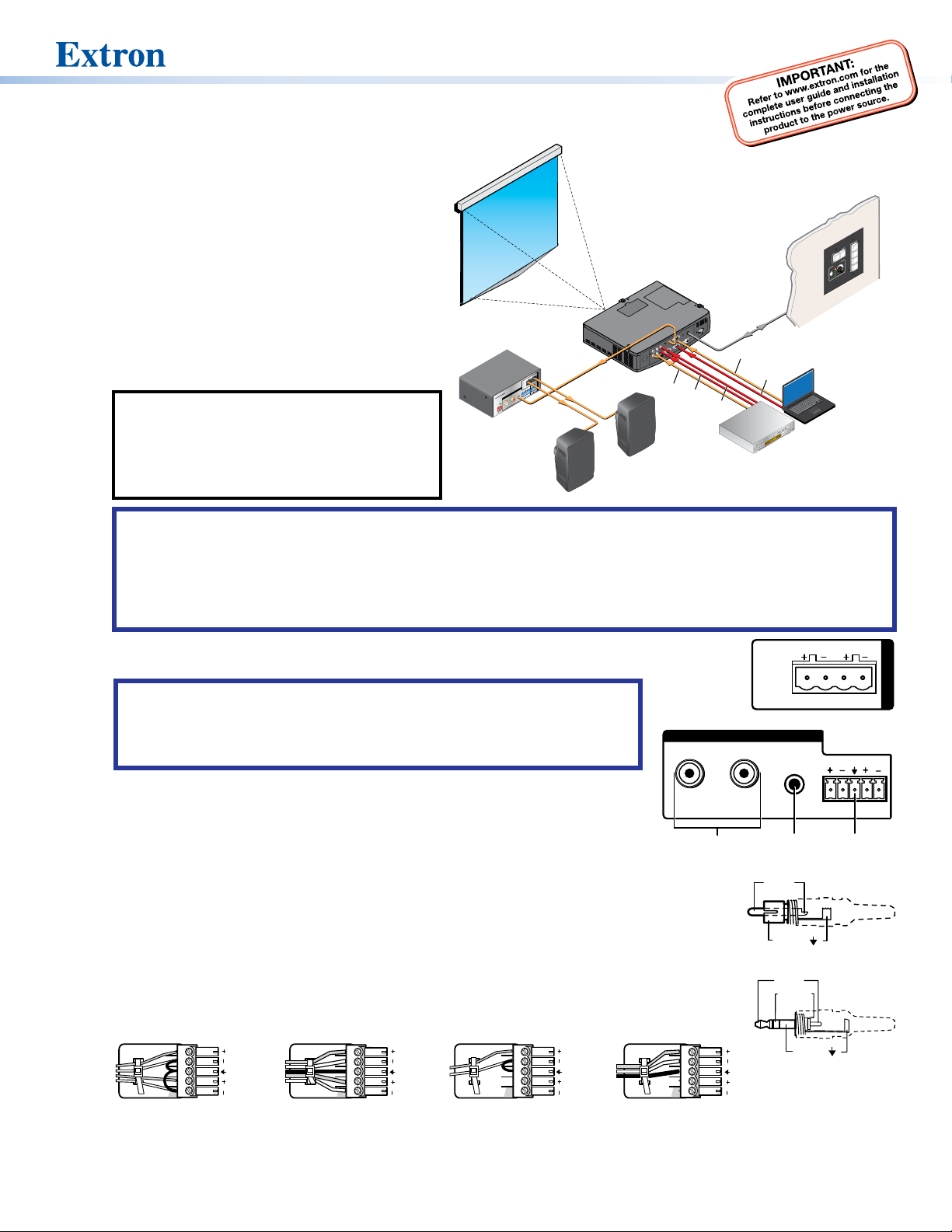
The Extron MPA 152 Plus is an ENERGY STAR® qualied
mini power amplier. It delivers up to 15watts (rms) per
channel stereo or dual mono into a 4ohm sound system,
or 8 watts (rms) per channel into an 8ohm system.
For complete instructions, see the MPA 152 Plus User
Guide, which is available at www.extron.com.
Installation
To install and set up an MPA 152 Plus, follow these steps:
1. Turn off all equipment and disconnect from power
sources.
2. Mount the Extron MPA 152 Plus on a rack, under a
desk, or on a projector pole.
NOTE: Use only the two round mounting holes
for mounting the MPA 152 Plus. The other
four (hexagonal) holes anchor stand‑offs for
the internal circuit boards. Using them may
damage the amplier and does not provide
secure mounting for the unit.
ATTENTION:
z Although the amplier is plenum rated, the power supply provided with it is not. The power supply must not be
placed in the plenum space. Cables to and from the amplier must be plenum rated.
z Bien que l’amplicateur soit conforme à la norme relative aux faux plafonds, la source d’alimentation fournie avec ne
l’est pas. Les câbles depuis et vers l’amplicateur doivent aussi être classés plenum. La source d’alimentation ne doit
pas être placée dans l’espace plenum.
INPUTS
MPA 152 Plus
R
POWER
12V
0.7A MAX
L
Extron
MPA 152 Plus
Mini Power
Amplier
1
EO
VID
2
X
DISPLAY
AU
FF
EO
O
VID
3
ON
PC
4
VOLUME
IMAGE
CONFIG
MUTE
Projector
RS-232 or
IR Projector
control
Audio
OUTPUT REMOTE
Ω
R
4
/
Ω
8
L
CLASS 2
WIRING
50mA
VC G
10V
R
L
Audio
Audio
Extron
SM 3
Full-range
Audio
S-Video
RGBHV
Video
DVD/VCR
Combo
MLC 104 IP PLUS
Extron
Extron
MLC 104 IP Plus
MediaLink Controller
with IP Link
Laptop
3. Attach the speakers to the MPA 152 Plus output, using the 4‑pole, 5mmcaptive screw receptacle
(see the gure at right).
ATTENTION:
z Do not ground or short the speaker outputs as this will damage the amplier.
z Ne pas mettre à la terre ni créer de court‑circuit dans les sorties de
l’enceinte, an d’éviter tout risque de détérioration de l’amplicateur.
4. Attach inputs to the MPA 152 Plus unit from the audio source, the projector, or
both. There are three audio inputs (shown in the gure at right), which can be used
L
individually or together.
One pair of RCA receptacles — these receptacles accept unbalanced, line
1
1112
level audio signals. The input can be stereo, using two RCA connectors, or
mono, using a single RCAconnector plugged into the left receptacle. If unused,
the receptacles automatically terminate to lower the noise oor.
One 3.5 mm stereo tip-ring-sleeve receptacle — this input also accepts
2
unbalanced, line level audio signals through a 3.5 mm tip ring sleeve (TRS)
stereo connector. If unused, the receptacle automatically terminates to lower the
noise oor.
One 3.5 mm, 5-pole captive screw receptacle — this 5‑pole 3.5 mm captive
3
screw receptacle accepts line level, balanced or unbalanced, mono or stereo
audio signals.
Tip
LR
Tip
ve
Tip
ve
Ring
Sleeves
Tip
Ring
LR
Tip
Sleeve
LR
Tip
Ring
Sleeve
/
4Ω8
Ω
CLASS 2
WIRING
INPUTS
R
Sleeve ( )
Tip (L)
Ring (R)
LR
Sleeve ( )
3.5 mm TRS Connector
R
L
R
L
3
RCA Connect
OUTPUT
1
Page 2
MPA 152 Plus • Setup Guide (Cont’d)
MPA 152 Plus
(5 mm) Max.
BASSLEVEL TREBLE
MINI POWER AMPLIFIER
STEREO
MONO
The MPA 152 Plus sums and weights the left unbalanced signals from the TRS and RCA receptacles. This summed, unbalanced
signal is then summed with the left balanced signal from the captive screw receptacle. The same applies to the right channel.
The left and right channels are then sent to the output ampliers in one of two ways, depending on how the front panel
switch is set (see the diagram to the right).
z Stereo: The left and right channels are sent to the left and right output amplifers respectively.
z Dual Mono: The left and right channels are summed and then the resulting mono signal is fed to both of the output
ampliers.
NOTE: The captive screw, RCA and TRS inputs are buffered.
5. Adjust the MPA 152 Plus input LEVEL, BASS, and TREBLE from the front panel (see gure at right).
DUAL
a. If necessary, unplug the remote connector from the unit (see step 6, below).
MPA 152 PLUS
b. If connecting the amplier to a system with adjustable volume, set the system volume
to its lowest point. Then adjust the MPA152 Plus front panel LEVEL potentiometer fully
counterclockwise without using excessive torque.
c. Set the system volume to its maximum volume level (no sound should come out).
d. Return to the MPA 152 Plus and raise the LEVEL until sound distortion rst occurs, then lower slightly until the distortion
disappears. This setting ensures that, whatever the system volume setting may be, no clipping occurs.
e. Adjust the BASS and TREBLE potentiometers to preference without using excessive torque.
ATTENTION:
z The default position of the LEVEL potentiometer when shipped is turned fully counter‑clockwise (fully attenuated). The
default position of the BASS and TREBLE potentiometers is 12 o’clock (at response).
z La position par défaut du potentiomètre de niveau lors de son expédition est orientée vers le sens antihoraire
(atténuation complète). La position par défaut des potentiomètres de graves et d’aigus est 12 h (réponse linéaire).
z Do not use a screwdriver to adjust the potentiometers. The potentiometers should only be adjusted as needed using
the included Extron tweeker (small screwdriver).
z Ne pas utiliser de tournevis pour ajuster les potentiomètres. Les potentiomètres doivent uniquement être ajustés
selon les besoins avec le petit tournevis Extron fourni.
z While potentiometer tuning knobs may look like screws, they do not function in the same manner. Use a light touch
when adjusting to avoid applying excessive torque to the potentiometers.
z Bien que les boutons de réglage du potentiomètre ressemblent à des vis, ils n’ont pas la même fonction. Exercez une
pression légère lors du réglage an d’éviter un serrage excessif des potentiomètres.
z Applying excessive torque can cause mechanical damage to the potentiometer, rendering it inoperable.
z Un serrage excessif peut endommager le potentiomètre, le rendant inutilisable.
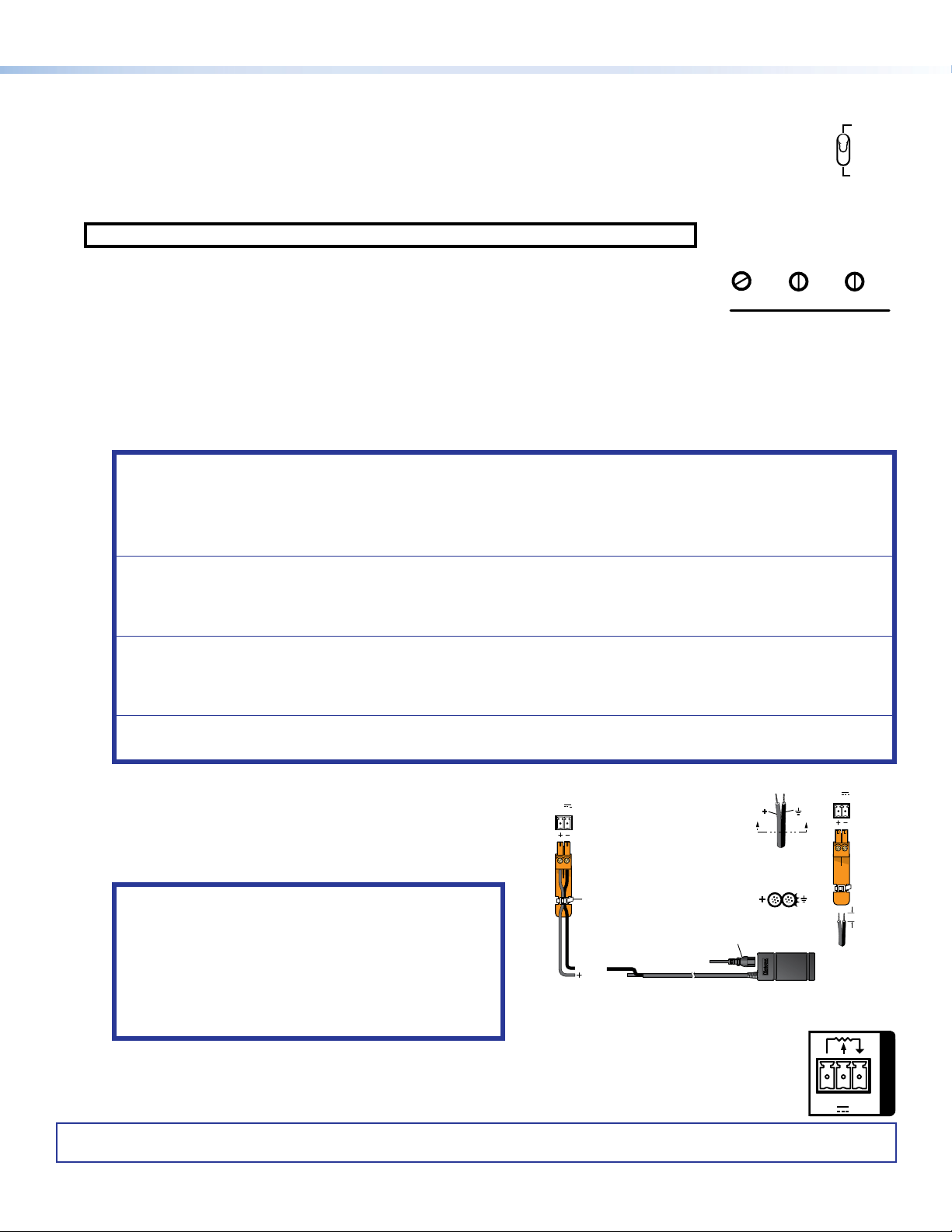
The MPA152 Plus ships with a 24 W desktop power supply.
The power cord connectors are correctly wired when shipped.
Connect the pre‑wired captive screw connector to the power
receptacle on the amplier (see the gure to the right).
To wire the connector yourself, ensure the power cords have
the correct polarity. The ground cord has ridges.
ATTENTION:
z See the attention notices in the Power Input section
of the MPA152 Plus Series User Guide for important
information about using power supplies.
z Reportez‑vous aux précautions d’emploi incluses
dans la section sur l’entrée d’alimentation du MPA152
Amplifier
POWER
12V
0.7A MAX
Power
Receptacle
Tie
Wrap
G
Ground
+12 VDC input
DC Power Cord
Captive Screw
Connector
Ground all
Devices
AC Power Cord
Ridges
Smooth
Power Supply
Output Cord
SECTION A–A
External Power Supply
(12 VDC, 2.0 A)
AA
Plus Series User Guide pour des informations
essentielles sur l’utilisation des sources d’alimentation.
6. The rear panel 3‑pole Remote captive screw port on the amplier can be used for remote control of the
volume by an Extron volume controller such as an Extron VCM100 AAP, VC 50, or MLA VC10 Plus. A
MediaLink controller can also adjust the audio volume via a network connection or by IR remote (see the
MPA 152 Plus Series User Guide).
For information on safety guidelines, regulatory compliances, EMI/EMF compatibility, accessibility, and related topics, see the
Extron Safety and Regulatory Compliance Guide on the Extron website.
© 2013‑2020 Extron — All rights reserved. www.extron.com. All trademarks mentioned are the property of their respective owners.
Worldwide Headquarters: Extron USA West, 1025 E. Ball Road, Anaheim, CA 92805, 800.633.9876
10V50mA
68-1320-52 Rev. C
POWER
12V
0.7A MAX
VCG
3/16"
REMOTE
12 20
 Loading...