

Page 1
MLC 206, MLC 206 AAP,
MLC 206 EC, MLC 206 AAP EC
MediaLink™ Controllers
68-601-01 Rev. B
Printed in the USA
11 02
Page 2

Precautions
Safety Instructions • English
This symbol is intended to alert the user of important operating and maintenance
(servicing) instructions in the literature provided with the equipment.
This symbol is intended to alert the user of the presence of uninsulated dangerous
voltage within the product's enclosure that may present a risk of electric shock.
Caution
Read Instructions • Read and understand all safety and operating instructions before using the
equipment.
Retain Instructions • The safety instructions should be kept for future reference.
Follow Warnings • Follow all warnings and instructions marked on the equipment or in the user
information.
Avoid Attachments • Do not use tools or attachments that are not recommended by the equipment
manufacturer because they may be hazardous.
Consignes de Sécurité • Français
Ce symbole sert à avertir l’utilisateur que la documentation fournie avec le matériel
contient des instructions importantes concernant l’exploitation et la maintenance
(réparation).
Ce symbole sert à avertir l’utilisateur de la présence dans le boîtier de l’appareil de
tensions dangereuses non isolées posant des risques d’électrocution.
Attention
Lire les instructions• Prendre connaissance de toutes les consignes de sécurité et d’exploitation avant
d’utiliser le matériel.
Conserver les instructions• Ranger les consignes de sécurité afin de pouvoir les consulter à l’avenir.
Respecter les avertissements • Observer tous les avertissements et consignes marqués sur le matériel ou
présentés dans la documentation utilisateur.
Eviter les pièces de fixation • Ne pas utiliser de pièces de fixation ni d’outils non recommandés par le
fabricant du matériel car cela risquerait de poser certains dangers.
Sicherheitsanleitungen • Deutsch
Dieses Symbol soll dem Benutzer in der im Lieferumfang enthaltenen
Dokumentation besonders wichtige Hinweise zur Bedienung und Wartung
(Instandhaltung) geben.
Dieses Symbol soll den Benutzer darauf aufmerksam machen, daß im Inneren des
Gehäuses dieses Produktes gefährliche Spannungen, die nicht isoliert sind und
die einen elektrischen Schock verursachen können, herrschen.
Achtung
Lesen der Anleitungen • Bevor Sie das Gerät zum ersten Mal verwenden, sollten Sie alle Sicherheits-und
Bedienungsanleitungen genau durchlesen und verstehen.
Aufbewahren der Anleitungen • Die Hinweise zur elektrischen Sicherheit des Produktes sollten Sie
aufbewahren, damit Sie im Bedarfsfall darauf zurückgreifen können.
Befolgen der Warnhinweise • Befolgen Sie alle Warnhinweise und Anleitungen auf dem Gerät oder in
der Benutzerdokumentation.
Keine Zusatzgeräte • Verwenden Sie keine Werkzeuge oder Zusatzgeräte, die nicht ausdrücklich vom
Hersteller empfohlen wurden, da diese eine Gefahrenquelle darstellen können.
Warning
Power sources • This equipment should be operated only from the power source indicated on the
product. This equipment is intended to be used with a main power system with a grounded
(neutral) conductor. The third (grounding) pin is a safety feature, do not attempt to bypass or
disable it.
Power disconnection • To remove power from the equipment safely, remove all power cords from
the rear of the equipment, or the desktop power module (if detachable), or from the power
source receptacle (wall plug).
Power cord protection • Power cords should be routed so that they are not likely to be stepped on or
pinched by items placed upon or against them.
Servicing • Refer all servicing to qualified service personnel. There are no user-serviceable parts
inside. To prevent the risk of shock, do not attempt to service this equipment yourself because
opening or removing covers may expose you to dangerous voltage or other hazards.
Slots and openings • If the equipment has slots or holes in the enclosure, these are provided to
prevent overheating of sensitive components inside. These openings must never be blocked by
other objects.
Lithium battery • There is a danger of explosion if battery is incorrectly replaced. Replace it only
with the same or equivalent type recommended by the manufacturer. Dispose of used batteries
according to the manufacturer's instructions.
Avertissement
Alimentations• Ne faire fonctionner ce matériel qu’avec la source d’alimentation indiquée sur
l’appareil. Ce matériel doit être utilisé avec une alimentation principale comportant un fil de
terre (neutre). Le troisième contact (de mise à la terre) constitue un dispositif de sécurité :
n’essayez pas de la contourner ni de la désactiver.
Déconnexion de l’alimentation• Pour mettre le matériel hors tension sans danger, déconnectez tous
les cordons d’alimentation de l’arrière de l’appareil ou du module d’alimentation de bureau (s’il
est amovible) ou encore de la prise secteur.
Protection du cordon d’alimentation • Acheminer les cordons d’alimentation de manière à ce que
personne ne risque de marcher dessus et à ce qu’ils ne soient pas écrasés ou pincés par des
objets.
Réparation-maintenance • Faire exécuter toutes les interventions de réparation-maintenance par un
technicien qualifié. Aucun des éléments internes ne peut être réparé par l’utilisateur. Afin
d’éviter tout danger d’électrocution, l’utilisateur ne doit pas essayer de procéder lui-même à ces
opérations car l’ouverture ou le retrait des couvercles risquent de l’exposer à de hautes tensions
et autres dangers.
Fentes et orifices • Si le boîtier de l’appareil comporte des fentes ou des orifices, ceux-ci servent à
empêcher les composants internes sensibles de surchauffer. Ces ouvertures ne doivent jamais
être bloquées par des objets.
Lithium Batterie • Il a danger d'explosion s'll y a remplacment incorrect de la batterie. Remplacer
uniquement avec une batterie du meme type ou d'un ype equivalent recommande par le
constructeur. Mettre au reut les batteries usagees conformement aux instructions du fabricant.
Vorsicht
Stromquellen • Dieses Gerät sollte nur über die auf dem Produkt angegebene Stromquelle betrieben
werden. Dieses Gerät wurde für eine Verwendung mit einer Hauptstromleitung mit einem
geerdeten (neutralen) Leiter konzipiert. Der dritte Kontakt ist für einen Erdanschluß, und stellt
eine Sicherheitsfunktion dar. Diese sollte nicht umgangen oder außer Betrieb gesetzt werden.
Stromunterbrechung • Um das Gerät auf sichere Weise vom Netz zu trennen, sollten Sie alle
Netzkabel aus der Rückseite des Gerätes, aus der externen Stomversorgung (falls dies möglich
ist) oder aus der Wandsteckdose ziehen.
Schutz des Netzkabels • Netzkabel sollten stets so verlegt werden, daß sie nicht im Weg liegen und
niemand darauf treten kann oder Objekte darauf- oder unmittelbar dagegengestellt werden
können.
Wartung • Alle Wartungsmaßnahmen sollten nur von qualifiziertem Servicepersonal durchgeführt
werden. Die internen Komponenten des Gerätes sind wartungsfrei. Zur Vermeidung eines
elektrischen Schocks versuchen Sie in keinem Fall, dieses Gerät selbst öffnen, da beim Entfernen
der Abdeckungen die Gefahr eines elektrischen Schlags und/oder andere Gefahren bestehen.
Schlitze und Öffnungen • Wenn das Gerät Schlitze oder Löcher im Gehäuse aufweist, dienen diese
zur Vermeidung einer Überhitzung der empfindlichen Teile im Inneren. Diese Öffnungen dürfen
niemals von anderen Objekten blockiert werden.
Litium-Batterie • Explosionsgefahr, falls die Batterie nicht richtig ersetzt wird. Ersetzen Sie
verbrauchte Batterien nur durch den gleichen oder einen vergleichbaren Batterietyp, der auch
vom Hersteller empfohlen wird. Entsorgen Sie verbrauchte Batterien bitte gemäß den
Herstelleranweisungen.
Instrucciones de seguridad • Español
Este símbolo se utiliza para advertir al usuario sobre instrucciones importantes de
operación y mantenimiento (o cambio de partes) que se desean destacar en el
contenido de la documentación suministrada con los equipos.
Este símbolo se utiliza para advertir al usuario sobre la presencia de elementos con
voltaje peligroso sin protección aislante, que puedan encontrarse dentro de la caja
o alojamiento del producto, y que puedan representar riesgo de electrocución.
Precaucion
Leer las instrucciones • Leer y analizar todas las instrucciones de operación y seguridad, antes de usar
el equipo.
Conservar las instrucciones • Conservar las instrucciones de seguridad para futura consulta.
Obedecer las advertencias • Todas las advertencias e instrucciones marcadas en el equipo o en la
documentación del usuario, deben ser obedecidas.
Evitar el uso de accesorios • No usar herramientas o accesorios que no sean especificamente
recomendados por el fabricante, ya que podrian implicar riesgos.
Advertencia
Alimentación eléctrica • Este equipo debe conectarse únicamente a la fuente/tipo de alimentación
eléctrica indicada en el mismo. La alimentación eléctrica de este equipo debe provenir de un
sistema de distribución general con conductor neutro a tierra. La tercera pata (puesta a tierra) es
una medida de seguridad, no puentearia ni eliminaria.
Desconexión de alimentación eléctrica • Para desconectar con seguridad la acometida de
alimentación eléctrica al equipo, desenchufar todos los cables de alimentación en el panel trasero
del equipo, o desenchufar el módulo de alimentación (si fuera independiente), o desenchufar el
cable del receptáculo de la pared.
Protección del cables de alimentación • Los cables de alimentación eléctrica se deben instalar en
lugares donde no sean pisados ni apretados por objetos que se puedan apoyar sobre ellos.
Reparaciones/mantenimiento • Solicitar siempre los servicios técnicos de personal calificado. En el
interior no hay partes a las que el usuario deba acceder. Para evitar riesgo de electrocución, no
intentar personalmente la reparación/mantenimiento de este equipo, ya que al abrir o extraer las
tapas puede quedar expuesto a voltajes peligrosos u otros riesgos.
Ranuras y aberturas • Si el equipo posee ranuras o orificios en su caja/alojamiento, es para evitar el
sobrecalientamiento de componentes internos sensibles. Estas aberturas nunca se deben obstruir
con otros objetos.
Batería de litio • Existe riesgo de explosión si esta batería se coloca en la posición incorrecta. Cambiar
esta batería únicamente con el mismo tipo (o su equivalente) recomendado por el fabricante.
Desachar las baterías usadas siguiendo las instrucciones del fabricante.
Page 3

Table of Contents
Chapter 1 • Introduction .......................................................................................................1-1
About the MLC 206 ............................................................................................................ 1-2
Features and Options........................................................................................................ 1-2
Standard features .............................................................................................................. 1-2
Options and accessories..................................................................................................... 1-2
MediaLink System Application Examples ..............................................................1-3
Chapter 2 • Installation .......................................................................................................... 2-1
Installation Overview ....................................................................................................... 2-2
UL Requirements ................................................................................................................. 2-2
Installation Procedures .................................................................................................... 2-3
Preparing the site and installing the wall box ................................................................. 2-3
Replacing faceplates and labels ........................................................................................ 2-4
Replacing the faceplate ...................................................................................................... 2-4
Replacing labels .................................................................................................................. 2-5
Rear/bottom panel cable connections .............................................................................. 2-6
Display (projector) and source control connections ......................................................... 2-6
Room/relay control connections ........................................................................................ 2-8
Accessory control connections ........................................................................................... 2-8
Extron switcher control connections ............................................................................... 2-10
Pinout guide..................................................................................................................... 2-13
Application diagram ........................................................................................................2-14
Mounting the MLC .......................................................................................................... 2-14
Mounting the MLC to an electrical box or mud ring ..................................................... 2-15
Mounting the MLC to a wall or furniture ....................................................................... 2-16
Rack mounting the MLC ................................................................................................... 2-16
Mounting the MLC in a Euro Channel............................................................................. 2-17
Chapter 3 • Operation ............................................................................................................. 3-1
Projector Control.................................................................................................................3-2
Projector control memory ................................................................................................. 3-2
Secondary mode and special projector functions ............................................................ 3-2
Front Panel Features and Operation ......................................................................... 3-2
Optional Control Modules and MLA-Remote ....................................................... 3-5
Chapter 4 • Serial Communication................................................................................. 4-1
RS-232 Programmer’s Guide .......................................................................................... 4-2
Host-to-MLC communications ...........................................................................................4-2
MLC-initiated messages ...................................................................................................... 4-2
Error responses .................................................................................................................... 4-2
Using the command/response tables ................................................................................. 4-3
Symbol definitions ........................................................................................................ 4-3
Command/response table for SIS commands ................................................................... 4-3
Command/response table for special function SIS commands ........................................ 4-5
MediaLink Controllers • Table of Contents
i
Page 4

Table of Contents, cont’d
Command/response table for advanced instructions
(for the Windows
Control Software for Windows
®
-based control program)..................................................................... 4-8
®
.................................................................................. 4-9
Installing the software ...................................................................................................... 4-9
Using the control program ................................................................................................ 4-9
User Mode ......................................................................................................................... 4-10
Special features ........................................................................................................... 4-10
Switcher (MLS) Config ...................................................................................................... 4-11
Controller (MLC) Config ................................................................................................... 4-12
Load Extron Driver ...................................................................................................... 4-12
Use Default Config ...................................................................................................... 4-12
Primary and secondary modes.................................................................................... 4-13
Display Power on/off................................................................................................... 4-13
Volume control settings.............................................................................................. 4-13
IR learning ................................................................................................................... 4-14
Associating IRCM-DV+ modules with MLC inputs..................................................... 4-15
Macros: associating MLC and control module buttons with each other................. 4-16
Advanced Projector Config .............................................................................................. 4-20
Relay & Misc. Options ....................................................................................................... 4-22
Special features ........................................................................................................... 4-22
Saving and restoring configurations .............................................................................. 4-24
Using the help program .................................................................................................. 4-24
Downloading and using projector drivers...................................................................... 4-24
Key to file names ............................................................................................................. 4-25
Using the emulation mode ............................................................................................. 4-26
Appendix A • Specifications, Part Numbers, and Accessories.................... A-1
Specifications....................................................................................................................... A-2
Part Numbers and Accessories ......................................................................................... A-3
Included Parts.................................................................................................................... A-3
Accessories......................................................................................................................... A-3
Cables ................................................................................................................................ A-4
Appendix B • Dimensions, Templates, Replacements, and Upgrades ....B-1
Dimensions ............................................................................................................................B-2
Templates ................................................................................................................................ B-3
Replacements and Upgrades.........................................................................................B-5
Firmware Replacement ...................................................................................................... B-5
All trademarks mentioned in this manual are the properties of their respective owners.
68-601-01 Rev. B
Printed in the USA
11 02
ii MediaLink Controllers • Table of Contents
Page 5

MediaLink™ Controllers
Chapter One
1
Introduction
About the MLC 206
Features and Options
MediaLink System Application Examples
Page 6

Introduction
About the MLC 206
The Extron MediaLink™ Controller (MLC 206) provides infrared (IR) and RS-232
remote control of a display device, contact closure control of items in a room, tally
outputs, and MediaLink Switcher control. Some models of Extron system
switchers can also be set as a peripheral switcher to the controller.
The MLC 206 is designed for use with audiovisual equipment in sites such as a
small classroom or boardroom. The MLC 206 comes with a 3-gang faceplate, the
MLC 206 AAP has a 5-gang faceplate, and the MLC 206 EC and MLC 206 AAP EC
have Euro Channel-mountable faceplates. A variety of optional faceplates are also
available.
“MLC”, “MLC 206”, and “controller” are used interchangeably in this manual to
refer to the MediaLink controller unit, no matter which faceplate is attached to it.
Most examples in this manual show the MLC 206 (3-gang size). The cabling,
operation and setup are identical for all models; the models differ only in how they
are mounted.
Features and Options
Standard features
Illuminated display — A button’s label is illuminated brightly when the button is
Projector control — Using downloadable, one-way RS-232 or IR driver, IR learning,
Room control — Items in a room, such as room lights, a screen, a projector lift, and
Secure enclosure — Ideal for installations in high traffic areas, the MLC is
Inactivity timer — The MLC can be set to automatically shut off the projector after
Audio volume adjustment — The audio system volume can be attenuated via a
selected and dimly when it is not selected.
or user-defined RS-232 commands, the MLC 206 can turn a projector’s (or
display’s) power on and off and also select between the projector’s inputs.
You can also create RS-232 commands for special functions such as focus and
zoom features.
other devices can be controlled via the MLC’s contact closure relays.
designed to prevent label alteration. Its backlit labels are not accessible after
installation.
a user-defined period.
rotary control. The MLC can be configured to adjust the volume on either the
projector or an optional MediaLink switcher.
Options and accessories
Remote control — The optional MLA-Remote provides infrared remote control of
the MLC unit from up to 30 feet away.
Expandability — An optional switcher can be attached in order to expand the
number of inputs to the projector.
Optional faceplates for a variety of mounting locations — The controller can
easily be mounted in a standard equipment rack, in a wall in an electrical
box, in a Euro Channel, in a Hoffman box, or in a lectern or other furniture.
Control modules — By connecting and setting up optional IR control modules, the
MLC can also be used to control video sources such as VCRs and DVD
players. Control modules are also available for controlling features of a
MediaLink Switcher (MLS) or for directly controlling the room control relays.
MediaLink Controllers • Introduction1-2
Page 7

MediaLink System Application Examples
Extron
MLC 206 AAP
Control Module(s)
DISPLAY
POWER
DVD
VCR
VOLUME
Portable
PC
MAX/
MIN
Extron
IR Control
IR Emitter
DVD
VCR
Controller
Tx
VCR CONTROL
REW PLAY FWD PAUSE STOP
Tx
DVD CONTROL
REW PLAY NEXT PAUSE STOP
MLC 206 AAP
MediaLink Controller
&
Relay Control
RS-232
Control
Audio/
Video
Projector
VCRDVD
MAC
TUNER
123456
Extron
MediaLink Switcher
WORK
CELL CAMERA
DOC
RGB
Composite
S-video
Control
MENU NEXT
Audio
Audio
VOLUME
ADJUST
MLS 306
MediaLink Switcher
SIGNAL
IR LINK
DVD
Audio Amp.
MLA-RemoteIR Link
1-3MediaLink Controllers • Introduction
Page 8
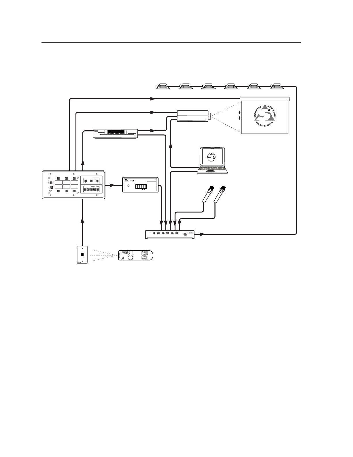
Introduction, cont’d
Relay Control
DISPLAY
POWER
AUX.
VCR
VIDEO
VOLUME
AUX.
MAX/
PC
RGB
MIN
Extron
Extron
MLC 206 AAP
Control Module
IMAGE
MUTE
AUTO
SYNC
IR Link
IR
Emitter
SCREEN POSITION
DOWN UPSTOP
VCR CONTROL
REW PLAY FWD PAUSE STOP
IR
Control
SIGNAL
IR LINK
RS-232 Control
RS-232
Tx
MLC 206 AAP
MediaLink Controller
VCR
Extron
MLA VC10
MLA-Remote
POWER/
STATUS
MLC/RS-232
POWER
A B
Video
Audio
MLA-VC10
Control
Video
Audio
Audio Amplifier
Projector
Laptop
Microphones
MediaLink Controllers • Introduction1-4
Page 9

MediaLink™ Controllers
Chapter Two
2
Installation
Installation Overview
UL Requirements
Installation Procedures
Page 10
Installation
Installation Overview
To install and set up a MediaLink Controller, follow these steps:
CAUTION
If applicable, prepare the installation site: cut a hole in the wall/furniture,
1
install the electrical box or mud ring, and prepare the cables. Instructions are
included in this manual and/or with the optional faceplate, mounting device,
or wall box. See “Preparing the site and installing the wall box” in this
chapter.
Remove the faceplate. See “Replacing faceplates and labels” in this chapter.
2
Make and install labels. See “Replacing faceplates and labels” in this chapter.
3
Reinstall the original faceplate or attach a different faceplate to the MLC. See
4
“Replacing faceplates and labels” in this chapter.
For an MLC 206 AAP EC or an optional faceplate with spaces for installing
5
Extron Architectural Adapter Plates (AAPs), attach the AAPs to the faceplate.
Attach cables to the rear of the MLC and to the projector, room devices,
6
optional control modules (IRCMs, ACMs, RCMs), optional IR Link,
IR Emitters or IR Broadcaster, and optional switcher. See “Rear/bottom panel
cable connections” in this chapter. If applicable, also attach cables to the back
of the optional AAP plates.
Connect power cords and turn on all the devices, including the MLC.
7
Configure the controller by using the included Windows®-based control
8
software or Simple Instruction Set™ commands. See chapter four.
Test the system: press the MLC’s buttons, watch the display, and listen to the
9
audio output to determine whether the output devices are responding
correctly (powering on/off, switching inputs). If not, ensure that all devices
are plugged in and receiving power. Check the cabling; make adjustments as
needed.
Installation and service must be performed by authorized personnel only. UL
Listed electrical boxes are recommended. See “UL Requirements” below.
Attach the MLC to the wall, furniture, equipment rack, or Euro Channel.
10
A. Disconnect the MLC’s power supply at the source end (not at the MLC).
B. Disconnect the other devices’ power.
C. Secure the faceplate onto the UL-approved electrical wall box, the mud
ring, the wall or furniture, the rack, or the Euro Channel. See
“Mounting the MLC” in this chapter.
D. Restore power to the MLC and to the connected devices.
UL Requirements
The Underwriters Laboratories (UL) requirements listed below pertain to the
installation of the MLC into a wall or furniture.
1. This unit is not to be connected to a centralized DC power source or used
beyond its rated voltage range.
2. This unit must be installed in a UL listed junction box.
3. This unit must be installed in accordance with the National Electrical Code.
The Extron P/S 100 and other Extron power supplies may be used with the
MLC.
The UL approved electrical wall box (junction box) is not included with the
MLC; the installer is responsible for obtaining and installing the box.
MediaLink Controllers • Installation2-2
Page 11

Installation Procedures
The MLC can be installed into a wall, a Euro Channel, or furniture, or, if an optional
faceplate is used, it can be mounted directly in furniture or an equipment rack.
Follow the instructions appropriate to the mounting option you have selected.
Templates for optional faceplates are not detailed in this manual.
Preparing the site and installing the wall box
Choose a location that will allow cable runs without interference. Allow enough
depth for both the wall box and the cables. You may need to install the cables into
the wall, furniture, or conduits before installing the controller.
The installation must conform to national and local electrical codes and to the
equipment’s size requirements. Dimensional drawings of the MLC 206 and
MLC 206 AAP and actual-size cut-out templates are provided in appendix B of this
manual. Templates for the optional faceplates are included with each faceplate.
Installation using a UL listed wall box is recommended for most mounting options,
but mud rings or a Euro Channel can be used instead.
• The MLC 206 includes a three-gang faceplate, the MLC 206 AAP includes a fivegang faceplate with space for Extron AAPs. Each can be installed in a standard
electrical wall box that is at least 1.75” deep. Mud rings are also available.
• The EC models (MLC 206 EC, MLC 206 AAP EC) can be installed in a standard
Euro Channel.
• Optional faceplates are available that accept the MLC 206 and also have openings
for Extron AAPs. Some optional faceplates can be installed into various sizes
of standard electrical wall boxes. Other optional faceplates are designed to be
directly mounted into a lectern or other furniture.
1a. If you are using a wall box or installing a MLC using a lectern mounting
faceplate, make a 100% size photocopy of the cut-out template that
corresponds to the faceplate you are using, and cut out the center portion of it
as indicated on the template.
1b. If you are using a mud ring, use the template that came with the mud ring.
Cut out the indicated center portion.
2. Place the template (or the wall box or mud ring) against the installation
surface, and mark the guidelines for the opening on the wall or furniture.
3. Cut out the wall/furniture material from the marked area.
4. Check the opening size by inserting the wall box, mud ring, or MLC into the
opening. The box or mud ring (if used) and/or MLC should fit easily into the
opening. Enlarge or smooth the edges of the opening if needed.
5. Feed cables through the wall box punch-out holes, and secure them with cable
clamps to provide strain relief.
6. Exposed cable shields (braids or foil) are
potential sources of short circuits. Trim back
and/or insulate shields with heat shrink.
To prevent short circuits, the outer
foil shield can be cut back to the point
where the cable exits the cable clamp.
Both braided and foil shields should
be connected to an equipment ground
at the other end of the cable.
Grounding outer braided and foil shields
Wall Stud
Wall Box
Screws or Nails
Flush with
Wall Surface
2-3MediaLink Controllers • Installation
Page 12
Installation, cont’d
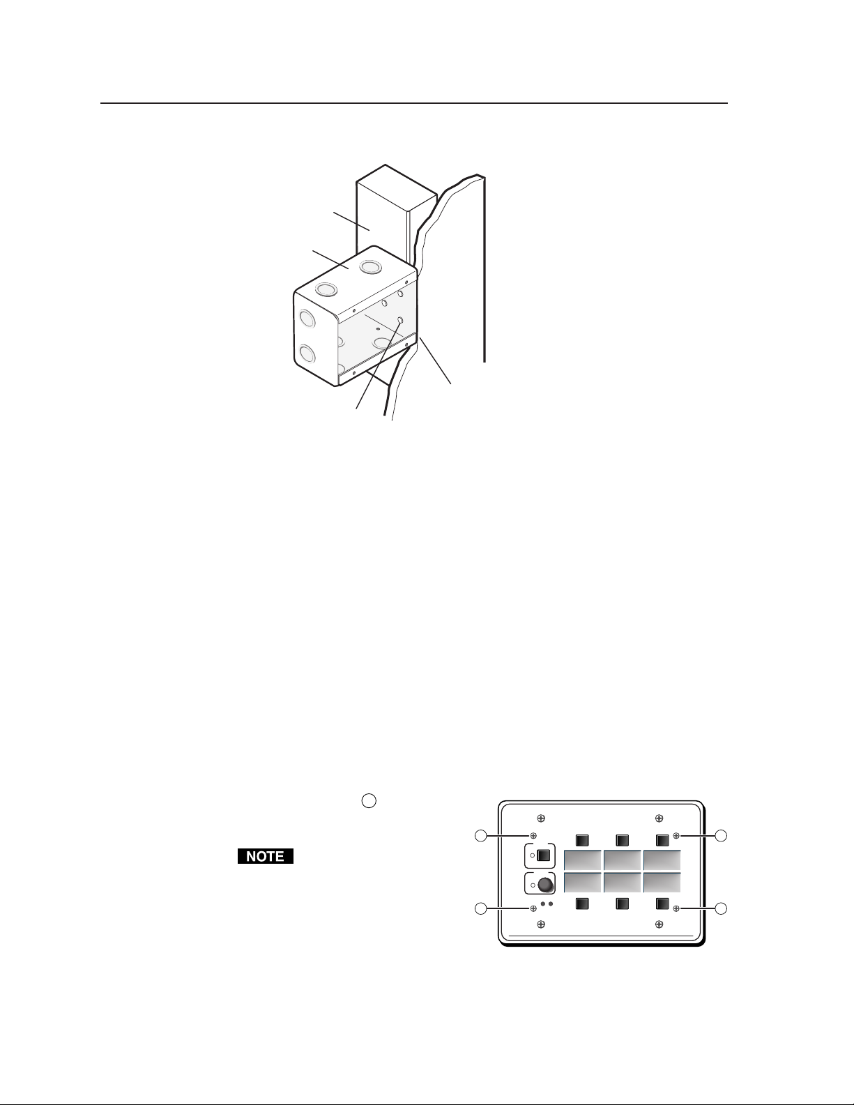
7a. If you are using a wall box, insert the wall box into the opening, and attach it
Wall Stud
Wall Box
Screws or Nails
Attaching a wall box to a wall stud
If attaching the wall box to wood, use four #8 or #10 screws or 10-penny nails.
A minimum of 1/2 inch (1.3 cm) of screw threads must penetrate the wood.
If attaching the wall box to metal studs or furniture, use four #8 or #10 selftapping sheet metal screws or machine bolts with matching nuts.
7b. If you are using a mud ring, follow the directions, if any, that came with the
mud ring to attach the clips that fasten the ring to the wall or furniture.
8. If desired, replace the faceplate and/or input labels.
9. Cable and test the MLC before fastening it into the wall box, mud ring, or
furniture.
to the wall stud/furniture with
nails or screws, leaving the front
edge flush with the outer wall or
furniture surface. The illustration
applies to all sizes of wall boxes.
Flush with
Wall Surface
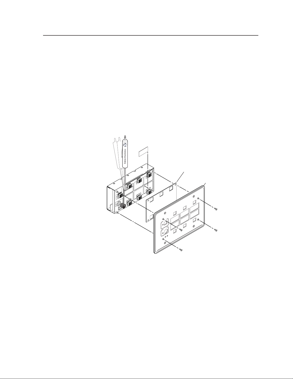
Replacing faceplates and labels
The MLC’s faceplate and the backlit input selection labels can be replaced. You can
replace the standard faceplate with an optional lectern mounting, rack mounting, or
wall mounting MLM faceplate for installation into a variety of locations. The
MLC 206 is shown in the following examples, but the instructions apply to all
models.
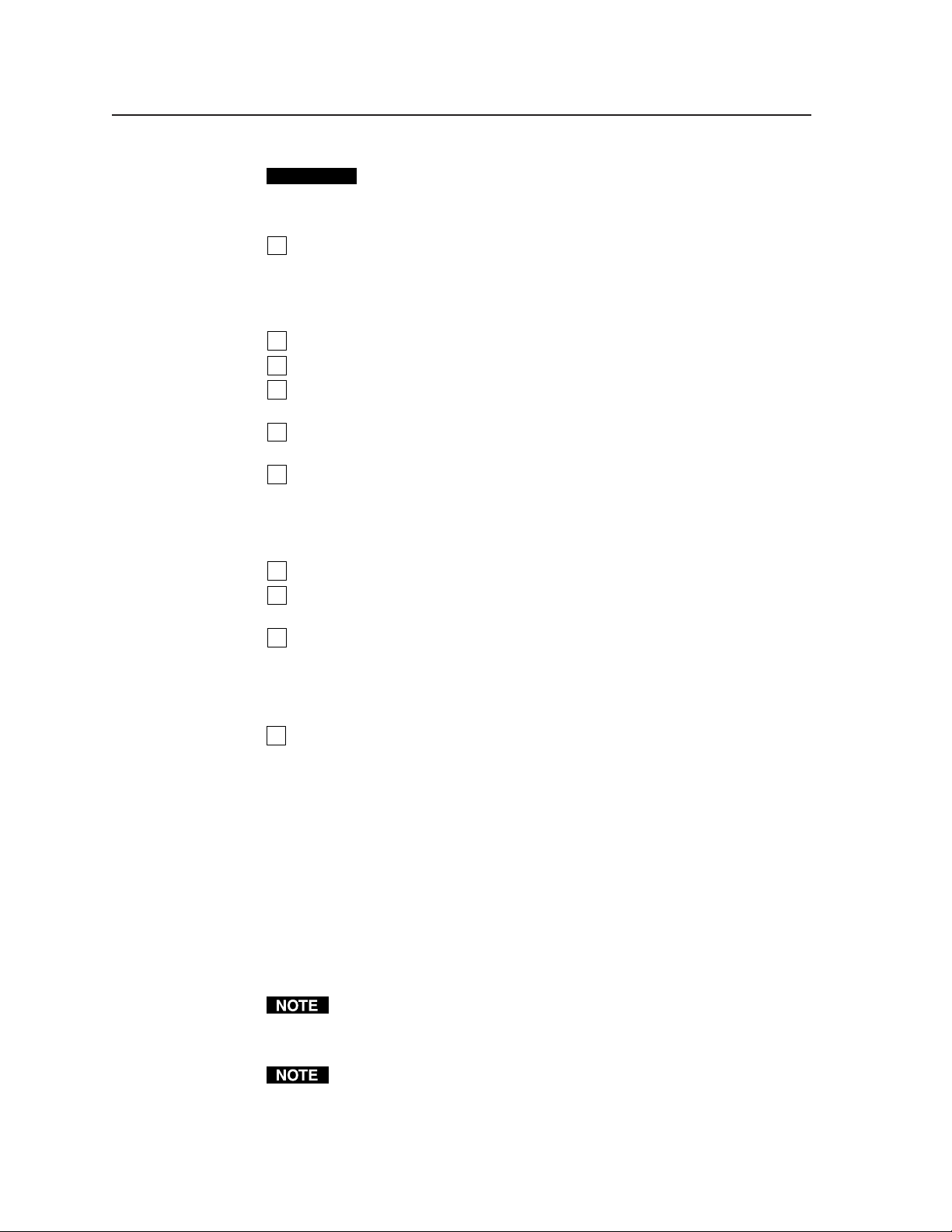
Replacing the faceplate
1. Use a small Philips screwdriver to remove the four faceplate attachment
screws marked 1 in the
picture at right, and keep them
for later use.
Do not remove these screws
while the MLC is installed
in a wall or furniture, or the
controller may fall down
into the wall/furniture or
wall box.
2. Lift the faceplate off the MLC.
3. Align the openings in the new faceplate with the controller’s buttons, knobs,
and LEDs, and place the new faceplate on the MLC.
4. Replace the four screws removed in step one, and hand tighten them.
1
1
Extron
DISPLAY
POWER
VCR DVD Laptop
VOLUME
MAX/
MIN
MediaLink Controller
1
1
MLC 206
MediaLink Controllers • Installation2-4
Page 13
Replacing labels
The backlit input selection labels are inaccessible once the MLC is installed into a
wall or furniture. The faceplate must be removed to gain access to the labels.
1. Use a small Philips screwdriver to remove the four faceplate attachment
screws, and keep them for later use.
2. Lift the faceplate off the MLC.
3. Lift off the transparent, protective, plastic window that covers the labels.
4. Lift off the transparent, rectangular label you want to replace, being careful
not to damage the circuits beneath it. You may need to use a small, flat
bladed screwdriver to gently pry the label out.
Window Labels
DVD
Plastic Window
Faceplate
VCR
DISPLAY
Extron
POWER
VOLUME
MAX/
MIN
r
MLC 206
k Controlle
MediaLin
Remove four screws.
5. Detach one of the preprinted labels or one of the blank labels from the sheet of
labels that is included with the MLC 206. Remove the protective film from the
front of the label. To create customized labels, use a label maker, such as a
Brother® P-touch®, and clear label material to print text to place on the blank
labels.
6. Insert the new label into the opening from which the other label was removed.
7. Repeat steps four through six for each label you wish to replace.
8. Place the plastic window back onto the MLC to cover the labels.
9. Align the openings in the faceplate with the buttons, knobs, and LEDs of the
MLC, and place the faceplate on the MLC.
10. Replace the four screws removed in step 1, and hand tighten them.
2-5MediaLink Controllers • Installation
Page 14
Installation, cont’d
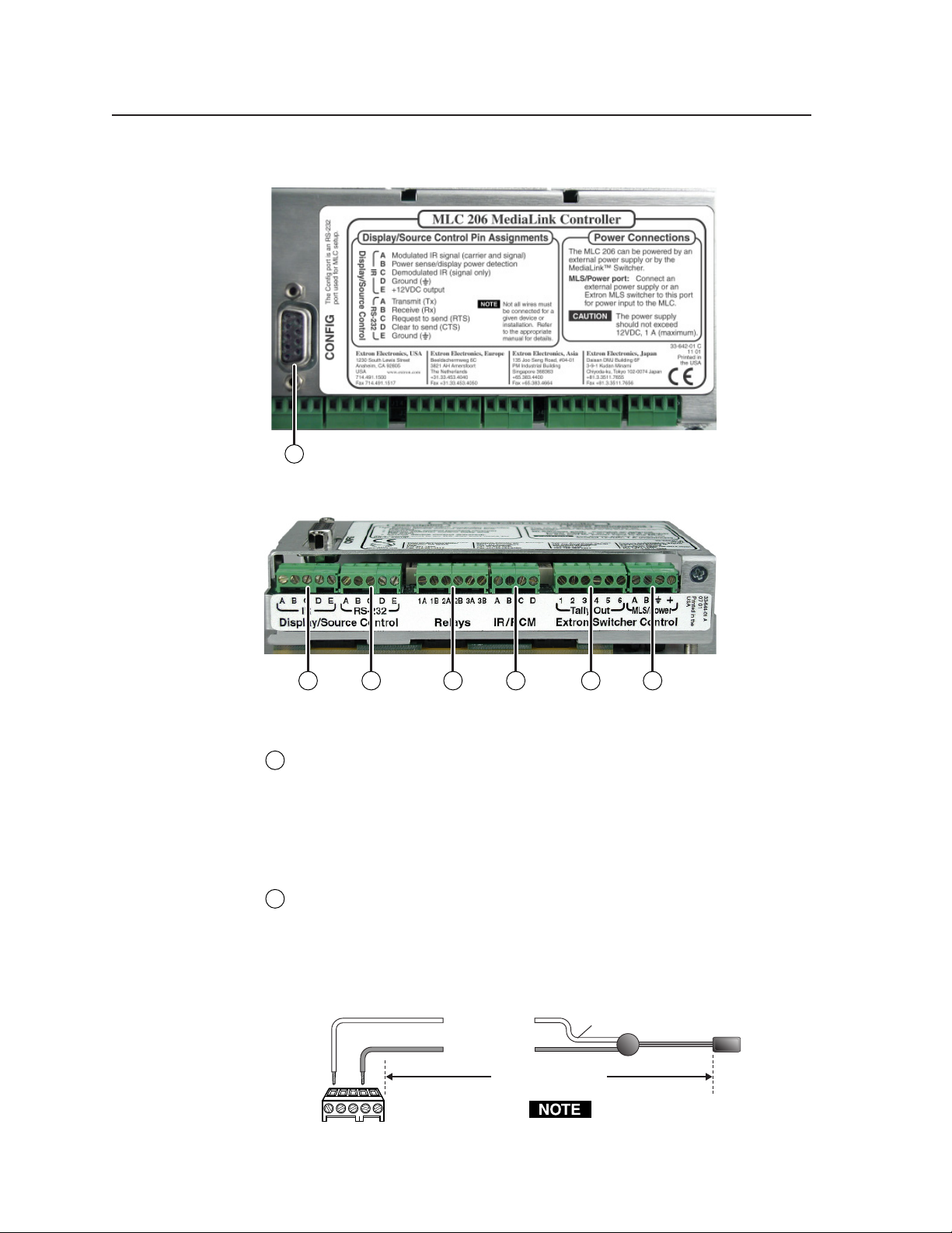
Rear/bottom panel cable connections
1
MLC 206 rear view
3 42 6 75
MLC 206 bottom view
Configuration port — This port is used for system configuration and for
1
loading control files into the MLC. Connect a host computer, third party
control system, or a terminal such as a personal digital assistant to the MLC
via this rear panel 9-pin HD female RS-232 connector. Commands and drivers
can be downloaded into or uploaded from the MLC via this port. See chapter
four for details about the setup software and downloading drivers.
Display (projector) and source control connections
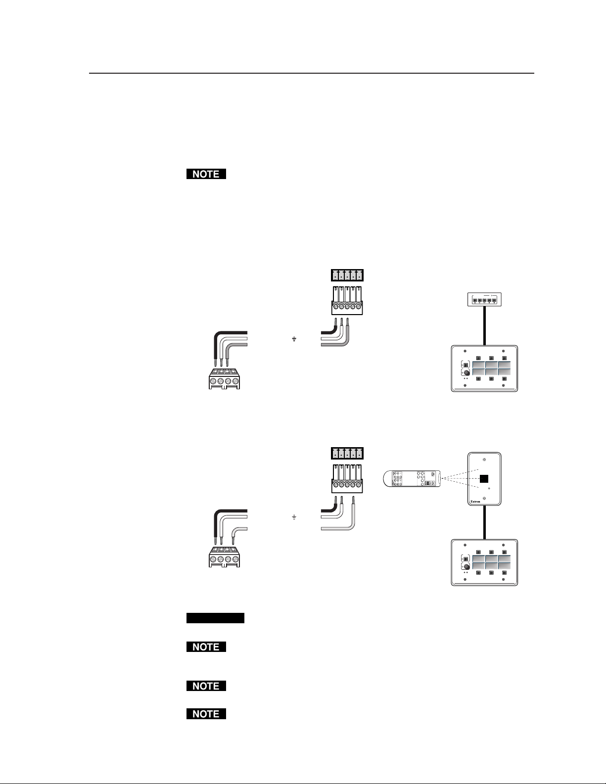
IR Display/Source Control connector — Infrared control signals are sent to
2
A/V devices via accessories connected to this port. Connect Extron
IR Emitters or an IR Broadcaster to this 3.5 mm, 5-pole direct insertion captive
screw connector so display and/or source devices can be controlled via
infrared commands from the MLC. Up to four IR Emitters can be connected
to the MLC via this connector at one time. Wire the connector as shown in the
following illustrations.
Modulated IR
BCDE
A
IR
MLC
IR control
port
A
Ground
D
110 feet (33.5 m) maximum
White striped wire only
Place the head of each IR Emitter
over or directly adjacent to the
controlled device’s IR receiver.
IR
Emitter
Connect
up to 4 IR
Emitters
(max.).
MediaLink Controllers • Installation2-6
Page 15
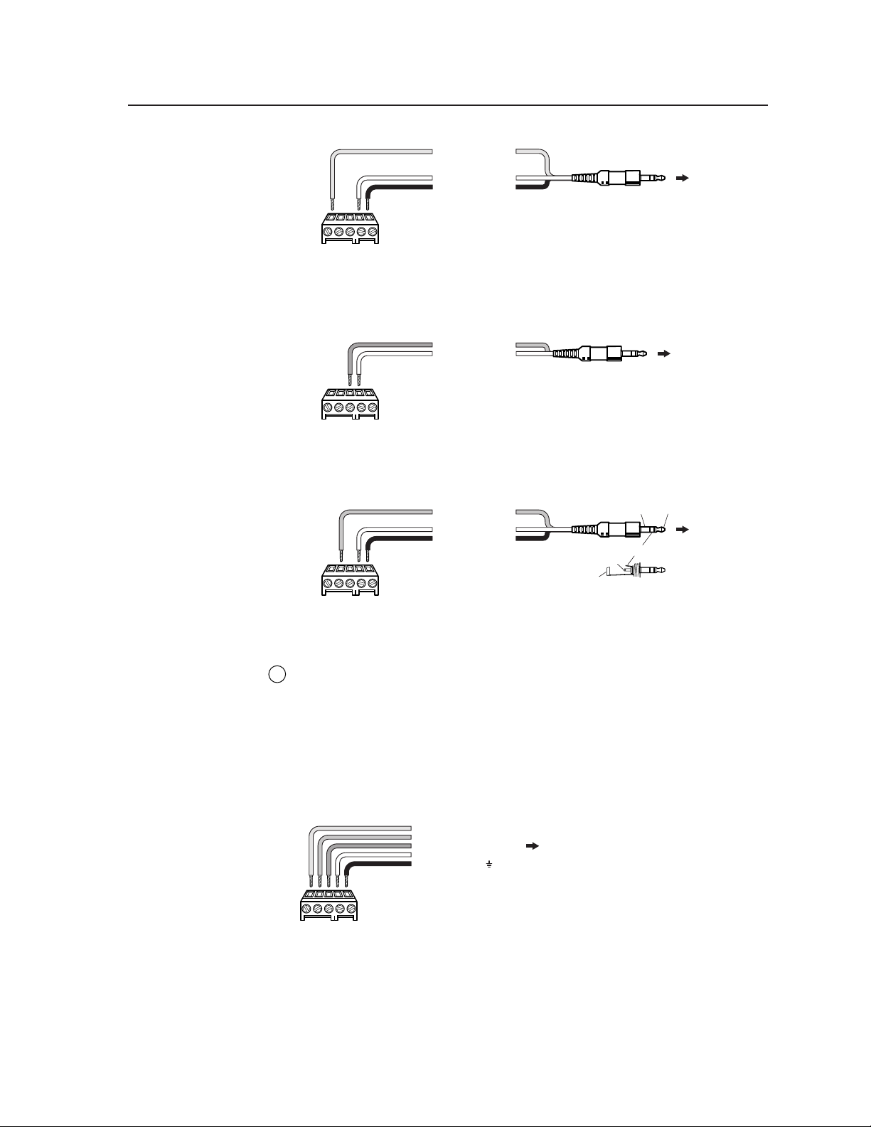
Modulated IR
A
Ground
D
+12VDC output
E
MLC
IR control
BCDE
A
port
IR
For the IR Broadcaster with emitter port
To IR Broadcaster
with Emitter port
(#60-272-02)
To the projector's
wired remote port
(Connector type and
pin configurations may
vary depending on the
projector model.)
BCDE
A
MLC
IR control
port
Demodulated IR
C
Ground
D
IR
For a wired projector remote port
Tip
(+12VDC)
To Display Power
Sensor
(#60-271-01)
BCDE
A
MLC
IR control
port
Power sense
B
Ground
D
+12VDC output
E
Tip (+12VDC)
Sleeve (Gnd)
Sleeve (Gnd)
Ring (power sense)
IR
For a projector current/power sensor
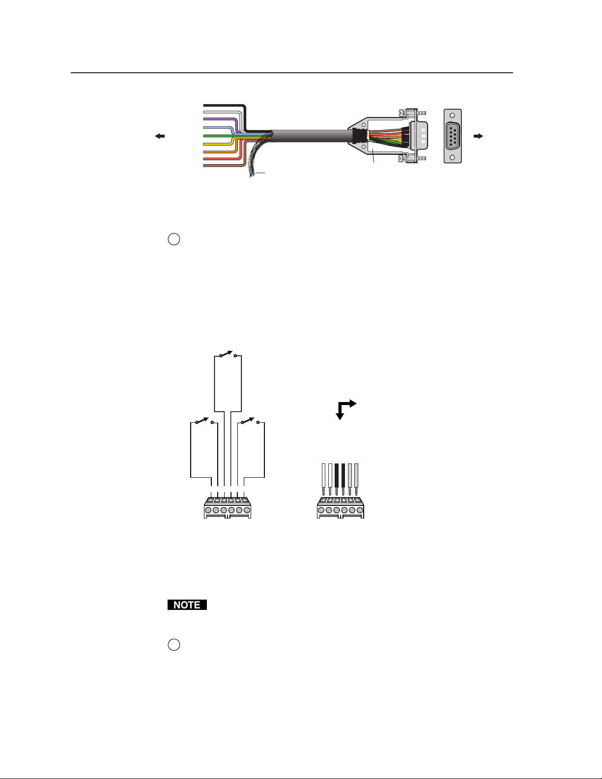
RS-232 Display/Source Control connector — The MLC sends out RS-232
3
commands via this port for controlling a projector or a peripheral Extron
system switcher. Guides for peripheral system switchers to the MLC and for
controlling specific models of projectors are available on the Extron Web site.
Connect a cable between the projector and this 3.5 mm, 5-pole direct insertion
captive screw connector for RS-232 projector control. Use the illustration
below as a guide to wiring the connector. Wiring will vary depending on the
projector model. In most cases only the transmit (Tx) and ground connections
will be needed.
Transmit (Tx)
A
Receive (Rx)
B
Request to send (RTS)
C
Clear to send (CTS)
D
Ground ( )
E
To the
display/projector's
RS-232 port
MLC
RS-232
control
BCDE
A
port
RS-232
We recommend using the UC 50’ universal projector control cable (for this
connection. One end of the cable is terminated with a female 9-pin D
connector, and the other end is unterminated. The UC 50’ pin assignments
are as shown in the following illustration. Refer to the projector’s manual for
the projector’s pin assignments in order to determine which of the cable’s
wires to connect to which of the MLC’s RS-232 pins.
2-7MediaLink Controllers • Installation
Page 16
Installation, cont’d
9
Black
8
Grey
Purple
7
Blue
To the
MLC 206
Orange
Room/relay control connections
6
5
Green
4
Yellow
3
2
Red
1
Brown
Pin #Color
Relay connector — This 3.5 mm, 6 pole direct insertion captive screw
4
connector provides three relays. Via the included software, these relays can
be set to control items in the room (such as lights, screens, and projector lifts)
when the display/projector is being powered up or down. They can also be
associated with other buttons. See chapters three (operation) and four (serial
communication) for details.
Use the software to specify momentary or latching contact. All the relays are
normally open, and the minimum rating is 24V, 1 A. See the following
diagrams of the relays and connector wiring, and refer to the screen,
projector lift, or AC controller manufacturer’s wiring guide.
UC Cable
Shield
Connector Shell
UC 50', 100', 200' Cable Color Codes
1
6
To the
projector
9
5
Normally open (2B)
Normally open (2A)
Normally open (1B)
Normally open (1A)
1A
1A
Relays
Normally open (3B)
Normally open (3A)
3B1B 2A 2B 3A
3B1B 2A 2B 3A
MLC 206 Relays
Accessory control connections
The MLC contains three relays, so you may install a maximum of one
RCM-SC or one RCM-SCLT in a system with an MLC. Refer to the Relay
Control Modules User’s Manual.
IR/RCM connector — Connect an optional IR Link signal repeater and/or
5
optional control modules (such as an Extron IRCM-VCR, IRCM-DVD,
IRCM-DVD+, IRCM-Tape, or an ACM, or RCM control module) here. The
IR Link receives infrared signals from the MLA Remote and sends them
directly to the MLC, allowing the MLA Remote to be used out of the line of
sight of and/or at a greater distance from the MLC than would be possible if
the IR Link were not used.
1A
Relay 1, pin B
Relay 1, pin A
Relay 2, pin A
Relays
Relay 2, pin B
Relay 3, pin A
3B1B 2A 2B 3A
To / from
room control
equipment
Relay 3, pin B
MediaLink Controllers • Installation2-8
Page 17
The control modules are Architectural Adapter Plate modules that can be
connected to the MLC to control devices such as VCR, tape, or DVD players,
or provide limited control of an optional MLS 306/506 Series switcher, or
other devices. Up to four control modules (in addition to the IR Link) can be
connected to the MLC, though the connector can hold wires for only 2-3 items
at a time, so you may wish to daisy chain the control modules together.
You must also set the control modules’ rear DIP switches so each control
module has a unique address number.
Wire the MLC’s IR/RCM 3.5 mm, 4-pole direct insertion captive screw
connector as shown in the following illustrations. Refer to the Control Modules
User’s Manual or the Relay Control Modules User’s Manual for information on
setting an address for each device. An Extron Comm-Link cable (see
appendix A for part numbers) is recommended.
A
+12VDC
Ground ( )
B
Control signal (IRCM)
MLC
/
RCM
IR
port
A
B
CC
ABCD
IR / RCM
MLC 206 to a control module
ABCD
IR / RCM
A
+12VDC
Ground ( )
B
Modulated IR (IR Link)
D
MLC
/
IRCM
IR
port
A
B
D
MLC 206 to an IR Link
ABCDE
ABCDE
Control
module
connector
IR Link
connector
MLA-Remote
IRCM control
module(s)
Extron
Extron
Total distance
from MLC:
150' (45.7 m)
max.
Tx
VCR CONTROL
REW PLAY FWD PAUSE STOP
DISPLAY
POWER
VCR DVD Laptop
VOLUME
MAX/
MIN
MLC 206
Total distance
from MLC:
150' (45.7 m) max.
SIGNAL
IR LINK
IR Link
IR signal
repeater
DISPLAY
POWER
VCR DVD Laptop
VOLUME
MAX/
MIN
MLC 206
MediaLink Controller
MediaLink Controller
MLC 206
MLC 206
CAUTION
Polarity is important. If the IR/RCM connector wiring specified in the
diagram is not followed, the equipment may be damaged.
Connect a maximum of one (1) IR Link. Do not connect more than one
IR Link (either in parallel or in series). Also, do not connect more than four
(4) control modules to the MLC.
The MLC contains three relays, so you may install a maximum of one
RCM-SC or one RCM-SCLT in a system with an MLC.
The control modules are not hot swappable. When you add or remove a control
module, you must cycle (disconnect, then reconnect) the MLC’s power before
the MLC can recognize the new module and the configuration change.
2-9MediaLink Controllers • Installation
Page 18
Installation, cont’d
Extron switcher control connections
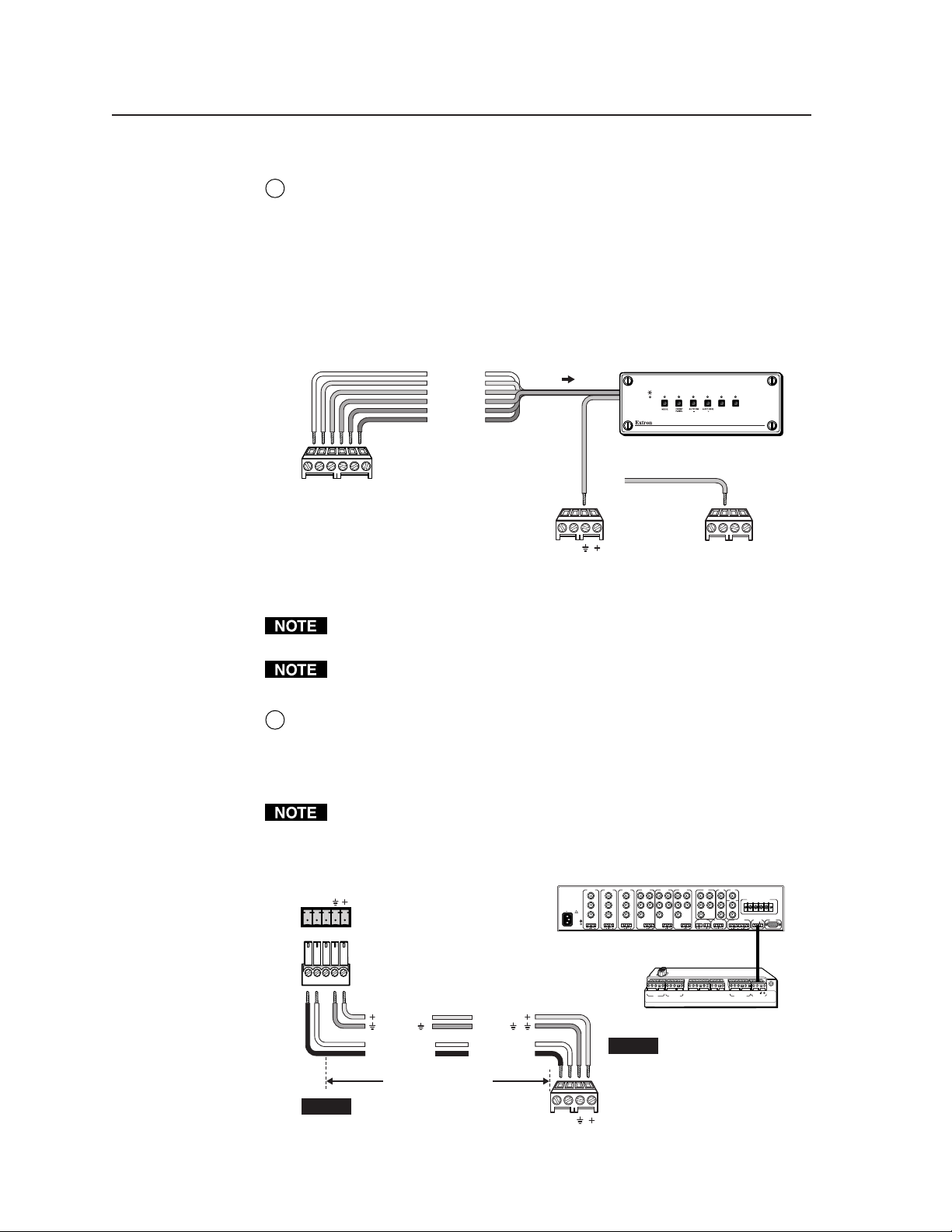
Contact closure Tally Out(put) connector — To effectively add more A/V
6
inputs to a projector, you aren’t limited to using a MediaLink switcher. If
desired, attach an Extron switcher that accepts contact closure control to this
3.5 mm, 6 pole direct insertion captive screw connector. Each pin corresponds
to a switcher front panel button. When a tally pin is selected, the pin changes
from a high (5V) to a low (0V) state. This momentary high-to-low change can
be used to trigger switching on various contact closure controllable Extron
switchers.
Wire the connector as shown here.
Input 1
1
Input 2
2
Input 3
3
Input 4
4
Input 5
5
Input 6
6
Connect the switcher's
contact closure
1
62345
ground pin to a
ground on the MLC.
To any
contact closure-
controllable
Extron switcher
123456
or
Tally Out
MLC
MLS/Power
AB
MLS / Power
port
ABCD
IR / RCM
MLC 206 Contact Closure Control
You must connect the ground pin of the switcher’s connector to a ground
connection on the MLC.
Only Extron switchers can be peripheral to the MLC via this tally output
contact closure connector.
MLS/Power connector — Connect a cable between this 3.5 mm, 4-pole direct
7
insertion captive screw connector and an optional Extron MLS switcher for
RS-232 control of the switcher and to provide power from the switcher to the
MLC. See the following diagram. With Extron Comm-Link cable, the
switcher and controller can be up to 250 feet (76.2 m) apart.
The commands issued from this port are standard Extron SIS™ commands,
and they follow the Extron switcher protocol (9600 baud rate, 8-bit, 1 stop bit,
no parity). The commands sent via the MLS/Power connector are fixed and
cannot be altered. See page 3-3 for additional details.
MLC/IR
ABC
MediaLink
Switcher
rear panel
MLC/IR port
INPUT 1
INPUT 2
INPUT 3
INPUT 4
VIDEO
VIDEO
RH/
RH/
R-Y
R-Y
HV
V
Y
Y
G
G
B-Y
B-Y
B
C
B
LR LR LR
C
100-240V 0.2A 50/60 Hz
.5A MAX
VIDEO
R-Y
Y
B-Y
C
L LRR LR
MLS 506MA Rear Panel
INPUT 5
HV
V
RH/
G
B
YUV
INPUT 6
HV
VIDEO
RGB
RH/
R-Y
HV
S-VIDEO
Y
Y
V
V
G
B
C
B-Y
AUX/MIXEFFECTS
FIXED VARIABLE
SENDLRRETURN
LR
LR
SW 6 AR MX
MLC
/
IRCM
IR
port
MONO AMPLIFIED OUTPUT
4 ohm
COMM 8 ohm 70V
MLC/IR RS232
AUDIO OUT
ABC
LRLR
CONTACT CLOSURE
33-644-01 A
07 01
Printed in the
123456
Tally Out
MLS
Extron Switcher Control
USA
/Power
+12VDC
Ground ( )
B
Receive (Rx)
A
Transmit (Tx)
Ground ( )
Transmit (Tx)
Receive (Rx)
250 feet (76.2 m) maximum
NOTE If you use cable that has a
drain wire, tie the drain wire
to ground at both ends.
+12VDC
B
A
AB
MLS / Power
NOTE
MLC
MLS/Power
port
ABCDE ABC
DE ABC ABD
1A 1B 2A 2B3A 3B
IR
RS-232
Display/Source Control
Relays IR/RCM
MLC 206 Bottom Panel
The switcher provides
power to the controller.
Connecting an MLC 206 to a MediaLink Switcher
MediaLink Controllers • Installation2-10
Page 19
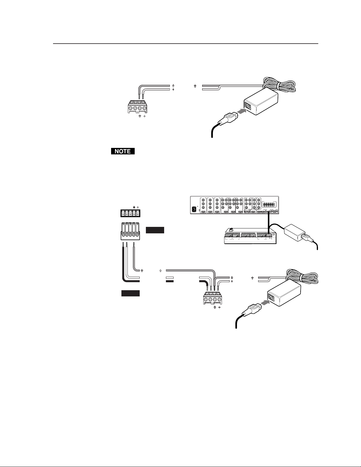
If you are not using an optional switcher, connect an external power supply
(12VDC, 1 A maximum) to this port to power the MLC as shown in the
following diagram.
Ground ( )
+12VDC input
An external
power supply
(12VDC, 1A max.)
AB
MLC
MLS/Power
port
MLS / Power
Connecting an MLC 206
Ground all devices
to an external power supply
Check the power supply’s polarity before connecting it to the MLC.
If you choose to power the MLC from a separate external power supply rather
than from a MLS 306/506/506 MA/506 SA or MLS 100 Series switcher, you
must connect a ground wire between the MLS and the MLC, as shown in the
following diagrams.
MLC/IR
ABC
MediaLink
Switcher
rear panel
MLC/IR port
NOTE
Ground ( )
B
Receive (Rx)
A
Transmit (Tx)
INPUT 1
INPUT 2
VIDEO
VIDEO
R-Y
R-Y
Y
Y
100-240V 0.2A 50/60 Hz
B-Y
B-Y
C
C
L LRR LR
.5A MAX
MLS 506MA Rear Panel
If using an external
power supply (instead of
the MLS) to power the
MLC, you must connect
a ground wire between
the MLC and MLS.
Transmit (Tx)
Receive (Rx)
B
A
INPUT 3
VIDEO
Y
C
INPUT 4
INPUT 5
RH/
RH/
R-Y
HV
HV
V
V
G
G
B-Y
B
B
LR LR LR
ABCDE ABC
IR
RS-232
Display/Source Control
MLC 206 Bottom Panel
+12VDC input
INPUT 6
RGB
RH/
RH/
HV
V
G
G
B
B
SENDLRRETURN
LR
DE ABC ABD
1A 1B 2A 2B 3A 3B
Relays IR/RCM
Ground ( )
HV
V
YUV
R-Y
Y
B-Y
AUX/MIXEFFECTS
LR
VIDEO
MONO AMPLIFIED OUTPUT
S-VIDEO
COMM 8 ohm 70V
Y
C
AUDIO OUT
FIXED VARIABLE
LRLR
123456
Tally Out
Extron Switcher Control
4 ohm
MLC/IR RS232
ABC
MLS
/Power
CONTACT CLOSURE
Printed in the
USA
33-644-01 A
07 01
External
Power Supply
NOTE If you use cable that has a
drain wire, tie the drain wire
to ground at both ends.
Connecting an MLC 206
to a MediaLink Switcher and
an external power supply
AB
MLS / Power
MLC
MLS/Power
port
Ground all devices
External
Power Supply
(12VDC, 1A max.)
2-11MediaLink Controllers • Installation
Page 20
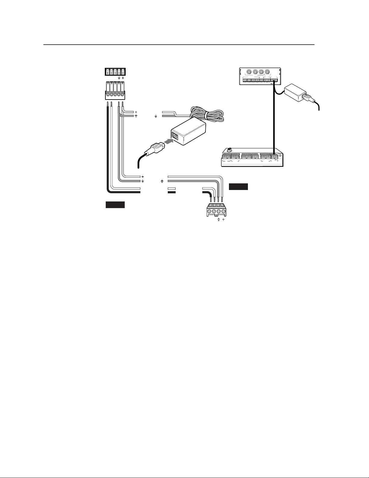
Installation, cont’d
POWER
AB
MLS100Series
Switcher
MLC/RS-232
Power Port
+12VDC input
Ground ( )
Ground all devices
+12VDC
Ground ( )
Receive (Rx)
B
A
Transmit (Tx)
NOTE If you use cable that has a
drain wire, tie the drain wire
to ground at both ends.
Connecting an MLC 206
to a MediaLink
VersaTools Switcher and an external power supply
External
Power Supply
(12VDC, 1A max.)
Transmit (Tx)
Receive (Rx)
B
A
AB
MLS / Power
3
2
1
INPUTS
OUTPUT
AUDIO INPUTS
OUT
AUX/MIX
LR
CONTROL/
4
LR
MONO
POWER
A
B
12V .5A MAX
LR
MLS 103 V
2
1
3
LR
LR
MLS 103 V
Rear Panel
250 ft
(76.2 m)
max.
ABCDE ABC
DE ABC ABD
IR
RS-232
Display/Source Control
1A 1B 2A 2B 3A 3B
Relays IR/ RCM
123456
Tally Out
MLS
Extron Switcher Control
MLC 206 Bottom Panel
NOTE You must connect a
ground wire between
the MLC and MLS.
MLC 206's
MLS/Power
Port
/Power
33-644-01 A
07 01
Printed in the
USA
External
Power Supply
MediaLink Controllers • Installation2-12
Page 21
ABCDE ABC
IR
Display/Source Control
Extron Switcher Control
Relays IR /RCM
RS-232
DE ABC ABD
1A 1B 2A 2B 3A 3B
123456
Tally Out
MLS
/Power
33-644-01 A
07 01
Printed in the
USA
+12VDC output
Modulated IR signal (carrier & signal)
Power sense/display power detection
Demodulated IR (signal only)
Ground ( )
E
D
C
B
A
Ground ( )
Transmit (Tx)
Receive (Rx)
Request to send (RTS)
Clear to send (CTS)
E
D
C
B
A
Ground ( )
+12VDC input
Receive (Rx)
Transmit (Tx)
B
A
C
Modulated IR (IR Link)
+12VDC output
Control signal (IRCM)
Ground ( )
D
B
A
Input 2
Input 1
Input 3
Input 4
Input 5
Input 6
6
5
4
3
2
1
Relay 1, pin B
Relay 1, pin A
Relay 2, pin A
Relay 2, pin B
Relay 3, pin A
Relay 3, pin B
1A
3B
1B
2A
2B
3A
To the
display/projector's
RS-232 port
To an IR Link
and/or MediaLink
Control Module(s)
To any contact closurecontrollable Extron switcher
To/from
room control
equipment
To/from a MediaLink Switcher
or
an external 12VDC, 1A power supply
To IR Emitter(s),
an IR Broadcaster,
the projector's wired
remote port, and/or a
Display Power Sensor
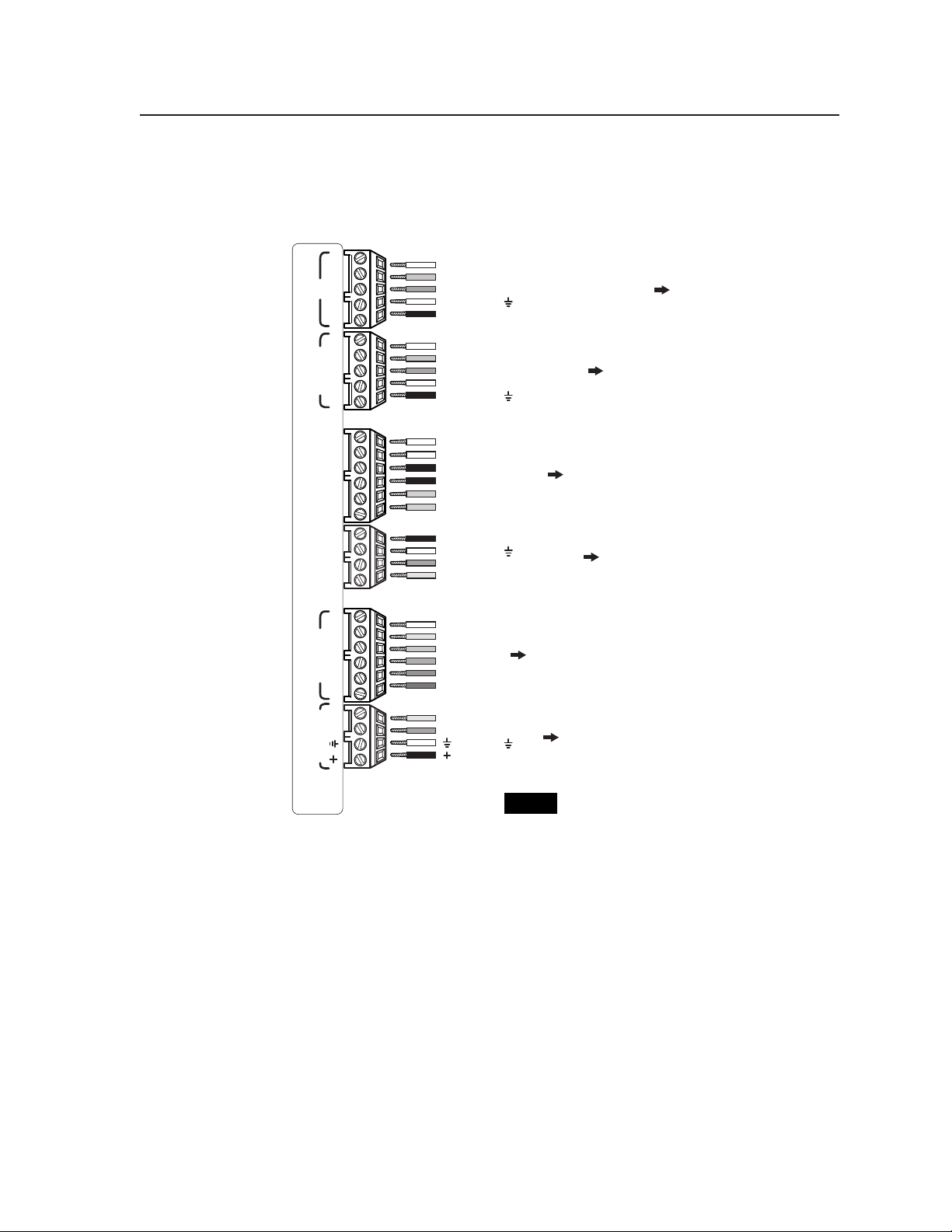
MediaLink Controller (MLC 206) bottom panel connector pinouts
NOTE Not all wires must be connected for a
given device or installation. Refer to
the appropriate manual for details.
Pinout guide
The illustration below summarizes the pin assignments of all of the MLC’s bottom
panel connectors that are covered in detail on pages 2-6 to 2-12.
2-13MediaLink Controllers • Installation
Page 22
Installation, cont’d
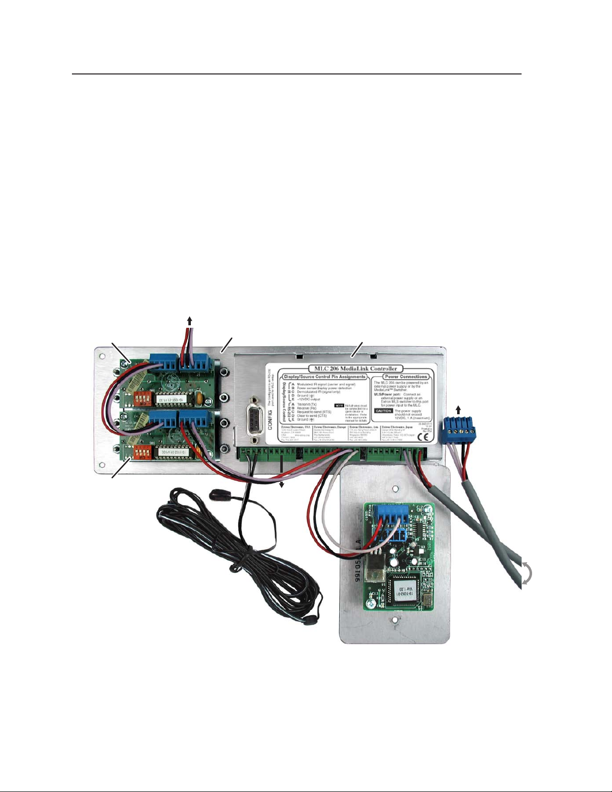
Application diagram
An example of one way to connect accessories to the controller is shown in the
photo below. The Config port is not shown with an RS-232 cable attached because
that connection is only required during setup.
This system includes an MLC mounted in an optional faceplate (MLM-LAAP) that
holds two control modules (IRCMs, ACMs, and/or RCMs), and an additional
control module is connected to the upper IRCM and mounted in another location.
An IR Link infrared repeater shares the IR/RCM port with the control modules (a
much longer cable than the one shown here would be used). IR Emitters are
connected to the MLC for controlling a VCR, DVD player, tape player or other
source device, and/or projector. An RS-232 connection to the projector could be
made from the adjacent RS-232 Display/Source Control port. Note the wiring on
both ends of the cable that connects the MLC’s MLS/Power port to an MediaLink
Switcher (MLS).
To 1–2 additional
IR Control Modules
(IRCMs)
IRCM #2
rear view
IRCM #1
rear view
MLM faceplate
IR Emitter
(Connect 1 per
each IRCM.)
RS-232
projector
connection
MLC 206 rear view
To an
MLS
switcher
Mounting the MLC
Once the system has been cabled, configured (see chapter four), and tested, the
controller can be installed in the wall, furniture, equipment rack, or Euro Channel.
MediaLink Controllers • Installation2-14
IR Link Infrared Repeater
rear view
Page 23

Mounting the MLC to an electrical box or mud ring
Detail A
0.75" #6-32 Screw
Backing Clip
Backing Clip
Sheet Rock
Sheet Rock
Mounting Bracket
Mounting Bracket
Detail B
1.25" #6-32 Screw
Backing Clip can
be in either orientation.
See Detail A or Detail B.
MLC 206
Extron
MediaLink Controller
MLC 206
DISPLAY
POWER
VOLUME
MAX/
MIN
VCR
DVD
Laptop
1. With power disconnected at the source, insert the MLC into the wall or furniture.
2. Mount the MLC to the wall box or mud ring mounting bracket with the
provided machine screws (as shown in the following illustrations), or attach it
directly to the furniture with wood or metal screws.
If the MLC (and any accessories such as control modules or an IR Link) is not
mounted to a grounded metal wall box,
• Ground each faceplate directly to an earth ground. Or...
• Tie each faceplate to it’s circuit board and power supply via a ground pin on
one of the connectors.
not tie a product’s faceplate to both a separate earth ground and the circuit
Do
ground (via a connector pin). If you tie a product to two different ground
sources, you may introduce ground loops or other grounding-related problems
into the system.
Cable
Clamp
Installation
Cable
Extron
Y
DISPLA
POWER
VOLUME
MAX/
MIN
DVD
VCR
MLC 206
Laptop
MLC 206
MediaLink Controller
Mounting the MLC to an electrical box or mud ring
2-15MediaLink Controllers • Installation
Page 24

Installation, cont’d
Mounting the MLC to a wall or furniture
1. Attach the optional lectern mounting faceplate to the MLC with machine
screws, as described on page 2-4 in “Replacing faceplates and labels” in this
chapter.
2. With power disconnected at the source, insert the MLC into the wall or
furniture.
3. Fasten the MLC and faceplate directly to the furniture or wall using wood
screws.
Rack mounting the MLC
1. Attach the optional rack mounting faceplate to the MLC with machine screws,
as described on page 2-4 in “Replacing faceplates and labels” in this chapter.
2. With power disconnected at the source, fasten the MLC and faceplate to the
rack using the supplied machine screws as shown in the following
illustration.
If the MLC (and any accessories such as control modules or an IR Link) is not
mounted to a grounded metal wall box,
• Ground each faceplate directly to an earth ground. Or...
• Tie each faceplate to it’s circuit board and power supply via a ground pin on
one of the connectors.
not tie a product’s faceplate to both a separate earth ground and the circuit
Do
ground (via a connector pin). If you tie a product to two different ground
sources, you may introduce ground loops or other grounding-related problems
into the system.
MediaLink
Laptop
DVD
VCR
DISPLAY
POWER
VOLUME
MAX/
MIN
Rack mounting the MLC
MediaLink Controllers • Installation2-16
Page 25

Mounting the MLC in a Euro Channel
1. With power disconnected at the source, insert the MLC 206 EC or
MLC 206 AAP EC into the Euro Channel. For wider types of Euro Channels,
you may need to insert a spacer plate first.
2. Mount the controller to the Euro Channel by attaching the faceplate to the two
backing plates using four #4-40 mounting screws. See the illustration below.
Make sure that the EuroChannel is grounded to an earth ground before
completing the installation.
Auxiliary
Video
Document
Camera
DVD
MediaLink
Lectern
Computer
VCR
Laptop
DISPLAY
POWER
VOLUME
MAX/
MIN
Backing Plate
Euro Channel
Mounting the MLC 206 EC or MLC 206 AAP EC to a Euro Channel
2-17MediaLink Controllers • Installation
Page 26

Installation, cont’d
MediaLink Controllers • Installation2-18
Page 27

MediaLink™ Controllers
Chapter Three
3
Operation
Projector Control
Front Panel Features and Operation
Optional Control Modules and MLA Remote
Page 28

Operation
Projector Control
Projector control memory
The MLC 206 can control a projector or other display device by using IR or RS-232
control. The MLC must be configured for projector control in one of the following
ways before it will send commands to the projector:
• An IR or an RS-232 driver file can be downloaded from a disk or the Extron Web
site into the MLC.
• RS-232 command strings can be entered directly from a host computer using the
supplied Windows-based software.
• IR commands can be entered directly from an IR remote control into the MLC
through IR learning. IR learning is convenient for installing new or updated
commands into the MLC in the field.
See chapter four and the MediaLink Control Program software for details on
setting up the MLC and for downloading, programming, or learning projector
control commands.
Each time a new projector driver is downloaded into the MLC, all previously
downloaded drivers (IR or RS-232) and user-defined RS-232 commands will be
replaced (overwritten or deleted) by the new driver. Similarly, entering a userdefined RS-232 command will cause the previously downloaded or user-defined
command to be replaced.
Secondary mode and special projector functions
The MLC has additional memory (up to 32 bytes per input selection button) for
storing commands for special projector functions such as zooming, focusing,
displaying color bars, or muting sound. These commands must be stored and the
MLC must be set up (see chapter four) to associate each command with a specific
input selection button. See the next page for LED and button names/numbers and
locations.
Follow these steps to execute the secondary mode commands:
1. Press input selection buttons three and four for three seconds to access the
secondary mode. The Display Power LED blinks rapidly while the secondary
mode is active.
2. While the secondary mode is active, press and release an input selection
button to send out the command that has been associated with it. The
button’s label blinks each time an input selection button is pressed and a
command is sent out.
The previously selected input remains active and will not change/switch while
the MLC is in the secondary mode.
3. To exit secondary mode, either press input selection buttons three and four
for three seconds and release them, or allow the MLC approximately ten
seconds of inactivity to time out to the regular (primary) mode.
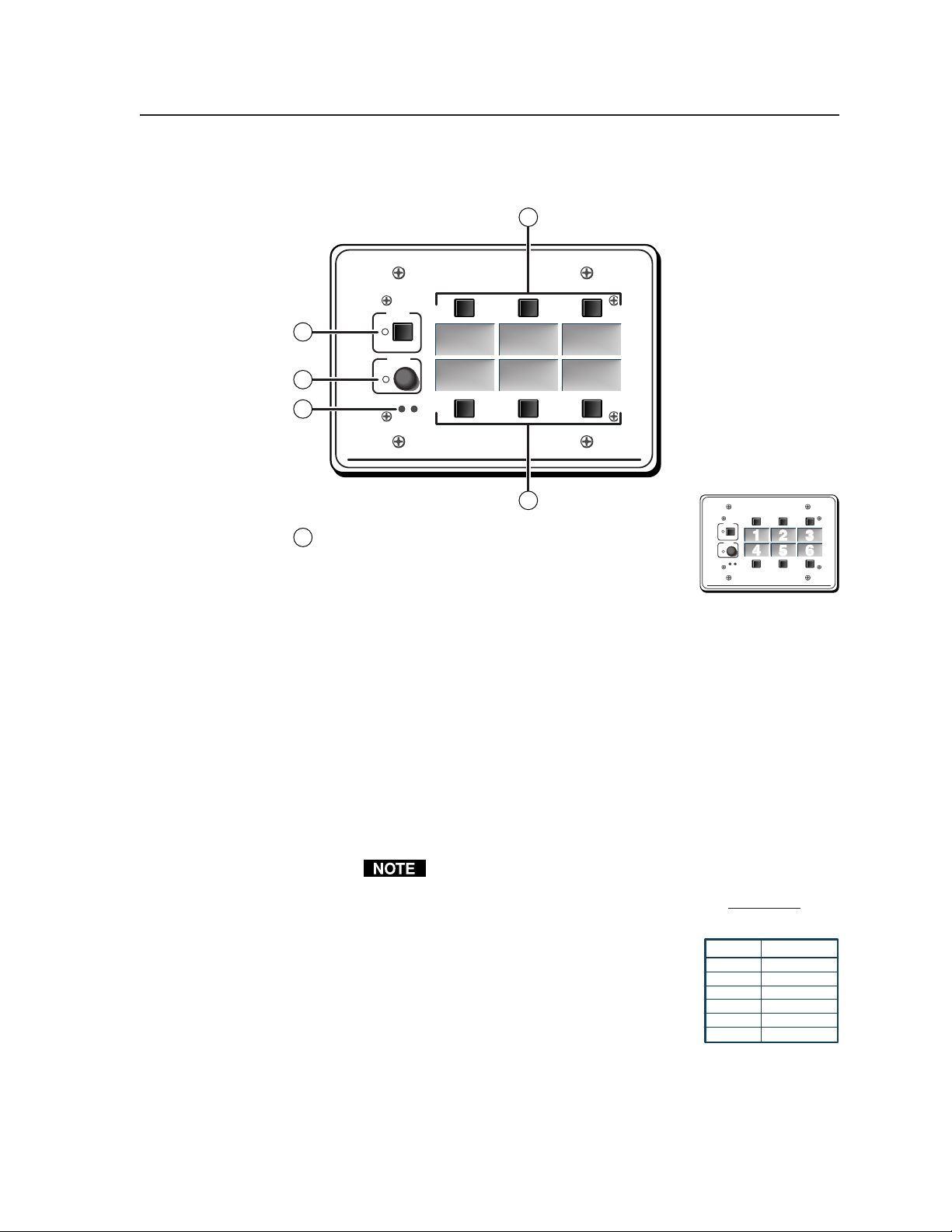
Front Panel Features and Operation
Each of the front panel buttons can have more than one function. A button may
serve one purpose in regular use (in primary mode), but can have another function
that is accessible only when the MLC is in secondary mode. See 1 in the
following picture.
Many features must be set up in order to function. See chapter four, “Serial
Communication”, for information about the MediaLink Control Program,
which you must use to set up many features of the MLC 206.
MediaLink Controllers • Operation3-2
Page 29
The MLC 206 is shown in the following examples, but the features and operation
are the same for all MLC models.
1
DISPLAY
POWER
2
VOLUME
3
MAX/
MIN
4
VCR DVD Laptop
Extron
MLC 206
MediaLink Controller
1
DISPLAY
POWER
Input selection buttons and backlit labels — From
1
the upper left to lower right these buttons are
numbered 1 through 6. See chapter 2 for instructions
on how to replace the labels.
Extron
VOLUME
MAX/
MIN
Basic operation — Press and release an input selection button to select the
designated input on the projector or the optional Extron switcher. All
labels are lit while the MLC receives power. The selected (active) input’s
label is lit more brightly than those of the nonselected inputs. If the
display power is off, the label backlighting will turn off (go dark) after a
period of inactivity (if no buttons are pressed for a while).
If the MLC is used without an optional switcher and the MLC has been
set up for use with a projector, only the number of inputs that are
available on the projector will be selectable on the MLC. If an optional
Extron switcher is connected to the MLC, all six input selection buttons
will be selectable. Which buttons are and aren’t part of the switching
rotation can be determined/set by the projector driver or via the
Windows-based setup program. See pages 4-7 and 4-12 and the
MediaLink Control Program’s Help file for details.
When an input selection button is part of the switching rotation,
pushing that button causes the MLC to send out an SIS input
change command via the MLS/Power connector in addition to
sending projector control commands out the Display/Source
Control IR or RS-232 ports.
The standard Extron SIS commands sent
via the MLS/Power connector are fixed
and cannot be altered. The command for
each input is shown at right.
Button Command
Input 1 1!
Input 2 2!
Input 3 3!
Input 4 4!
Input 5 5!
Input 6 6!
Additional and secondary functions —
IR/RS-232 command execution — Each input selection button can also
have IR commands or up to 32 bytes of RS-232 commands
associated with it. A command can be executed along with an
input switch by pressing the button while the MLC is in
primary mode. A different command can be executed by
123
456
MediaLink Controller
MLC 206
3-3MediaLink Controllers • Operation
Page 30

Operation, cont’d
pressing the button when the MLC is in the secondary mode or
via the Windows-based software.
The corresponding label flashes when a command associated with a
button is executed.
Relay triggering — A relay can be associated with a button. The relay
can be triggered by pressing a button only when the MLC is in
primary mode, or it can be triggered via the control software.
See pages 2-8, 4-3, 4-5, 4-10, 4-12, 4-22, and the note on page 4-18
for details.
If an input selection button is not part of the switching rotation
(does not cause input switching), the corresponding label flashes
when a momentary relay associated with a button is triggered, and
it lights steadily while a latching relay associated with the button
is active.
Secondary mode selection — If buttons 3 and 4 are simultaneously
pressed for three seconds, the MLC enters the secondary mode.
In this mode, input switching is temporarily disabled, and the
input selection buttons can be used to send various user-defined
RS-232 or IR commands to the projector (or other equipment).
Commands for special projector functions such as autosync,
focus, and zoom can be assigned to an input button and
executed when secondary mode is active.
While the secondary mode is active, the Display Power LED
blinks about twice per second. If a button is pressed in
secondary mode, the button’s label flashes briefly. Relays
cannot be triggered via the front panel when secondary mode is
active, only via the software.
To exit secondary mode, press and hold buttons 3 and 4, or
allow the MLC to time out to primary mode.
Display Power button and LED — The Display Power button has two blocks
2
of memory that can be programmed to store projector power-on and poweroff commands.
Basic operation — You must program the commands (see chapter four)
during MLC setup before this button will control the projector. To turn
the projector’s power on/off:
1. Press the Display Power button to turn the projector’s power on.
The MLC sends an RS-232 or IR power-on command to the
projector, the Display Power LED blinks for the period set for
power-up delay (refer to the Room & Misc. Options screen of the
control software for details), and then the LED remains steadily lit.
2. Once the projector is on, press and hold the Display Power button
for two seconds to turn the projector’s power off. The MLC sends a
power-off command to the projector, the LED blinks for the time set
for power-down delay, then the LED turns off. During the powerdown period, the MLC resends the power-off command.
The two-second press and hold period for Display Power Off can
be changed, via HyperTerminal only, to zero seconds by using a
special command (22 * X? #, where X? = 0 for a two-second delay,
or X? = 1 for no delay). See page 4-7.
The relays discussed in “Rear/bottom panel cable connections” in
chapter two can be turned on/off when the Display Power button is
pressed. Via the control software, each relay can also be associated with
MediaLink Controllers • Operation3-4
Page 31
either an input selection button or display power-up or display powerdown. See chapter two for information on the relays, and see chapter
four and the control software for details on changing settings for the relays.
Additional and secondary functions — While the secondary mode is active,
the Display Power LED blinks rapidly.
Volume adjustment knob and LED — Rotate this knob to adjust the audio
3
volume. The LED lights when the volume has reached the minimum or
maximum limit. The included control software lets you select whether this
knob will control the projector’s audio levels or the optional switcher’s audio
levels. If the knob controls the projector’s audio levels, the software allows
you to specify incremental adjustments or table-based adjustments. See the
MediaLink Control Software Help file for details.
IR signal pickup devices — These sensors allow for IR control of the MLC
4
and for IR learning. The IR remote control must be pointed directly at these
devices for best results. One device is an IR receiver that receives signals from
the MLA-Remote for controlling the MLC 206. The other is the IR learning
device. The MLC can “learn” commands in order to control the projector or
to control input devices such as a VCR or DVD players. IR learning of
projector control codes is only necessary if there are no RS-232 codes available
for that projector or if you need to customize the driver. The IR learning
procedure is discussed in the control software and later in this manual.
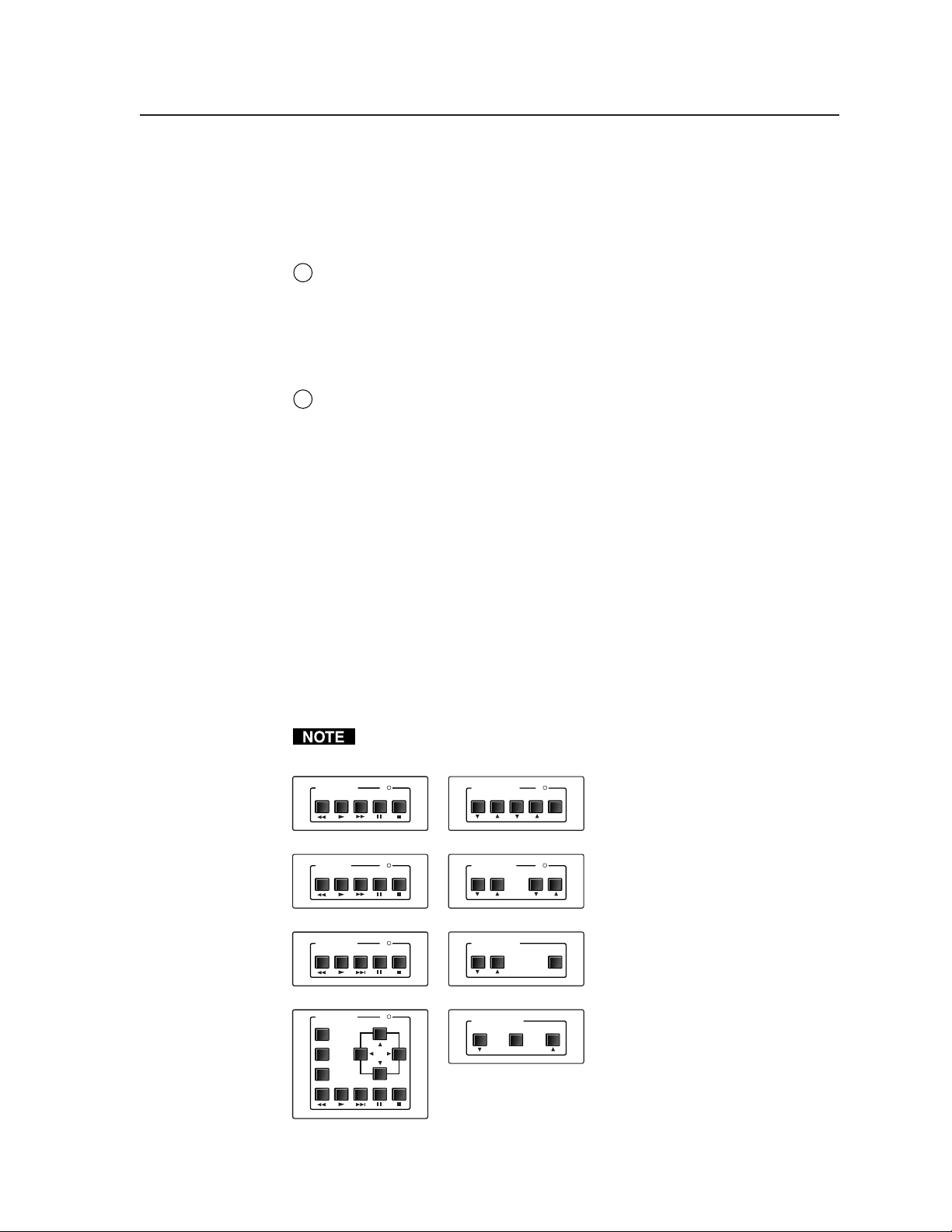
Optional Control Modules and MLA-Remote
The MLC has an additional thirty memory blocks in which IR or other commands
can be stored for control modules attached to the MLC. The MLC can “learn” IR
commands directly from a VCR’s, DVD’s, tape deck’s or other device’s remote
control. A learned command can be associated with each of the buttons on an
optional infrared control module (such as the Extron IRCM-VCR, IRCM-DVD,
IRCM-DVD+, IRCM-DV+, or IRCM-Tape) in order to allow limited control of
source devices. ACM control modules provide limited remote control of
adjustments to a peripheral MediaLink Switcher.
The control module must be connected to the MLC before you can perform IR
learning for the module’s buttons.
VCR CONTROL
REW PLAY FWD PAUSE STOP
Tx
MAX/
AUDIO CONTROL
INPUT LEVEL MIX LEVEL MUTE
MIN
A total of four control modules
(maximum) can be installed with
an MLC 206. Refer to the Control
IRCM-VCR
TAPE DECK
REW PLAY FWD PAUSE STOP
Tx
TONE CONTROL
BASS TREBLE
ACM-Level
MAX/
MIN
Modules User’s Manual and the
Relay Control Modules User’s
Manual for installation details.
See page 4-4 of this manual for
IRCM-Tape
DVD CONTROL
REW PLAY NEXT PAUSE STOP
IRCM-DVD
DVD CONTROL
MENU
TITLE
ENTER
PLAY NEXT PAUSE STOP
REW
IRCM-DVD+
ACM-Tone
Tx
Tx
ROOM CONTROL
SCREEN POSITION LIGHTING
ON / OFF
RCM-SCLT
SCREEN POSITION
DOWN UPSTOP
RCM-SC
special instructions for the
IRCM-DV+.
Optional IRCM, ACM, and RCM control modules
3-5MediaLink Controllers • Operation
Page 32

Operation, cont’d
The buttons on the optional MLA-Remote duplicate the
MLC’s front panel controls and also those of two Control
Modules (IRCMs) for normal operation. The MLA-Remote
can also be used to control a MediaLink Switcher (MLS). The
controller, control module, or switcher responds to commands
from the MLA-Remote as if the corresponding button or knob
were pressed or turned on the controller or switcher.
From a distance of no more than 30 feet and within 40° of the
axis, the MLA-Remote sends infrared (IR) signals to
• a MediaLink Controller via the controller’s front panel IR
pickup device or the IR pickup device of an optional IR
Link IR signal repeater.
• a MediaLink Switcher via a connected IR Link. The
switcher can receive signals from the MLA-Remote only
via an IR Link.
The MLA-Remote’s Display Power button and the VCR and
DVD control buttons will not function until commands have
been stored in the MLC’s memory. The MLA-Remote’s VCR
buttons control the first (lowest address numbered) IRCMVCR connected to the MLC. The DVD buttons control the
first (lowest address numbered) IRCM-DVD connected to the
MLC.
Commands are transmitted from the MLC’s Display/Source Control RS-232 port
(via hard wiring) and IR ports (via IR Emitters or optional IR Broadcaster) when the
corresponding button is pressed on the MLA-Remote or on the controller’s or
control module’s front panel. Refer to the Control Modules User’s Manual.
Setup operations cannot be performed from the
MLA-Remote.
The only control modules that can be controlled via the
MLA-Remote are the IRCM-VCR and IRCM-DVD.
MLA-Remote
IR remote control
MediaLink Controllers • Operation3-6
Page 33

MediaLink™ Controllers
Chapter Four
4
Serial Communication
RS-232 Programmer’s Guide
Control Software for Windows
Page 34

Serial Communication
DB9 Pin Locations
Female
51
96
The MLC can be remotely set up and controlled via a host computer or other
device (such as a control system) attached to the rear panel Configuration port.
The control device (host) can use either Extron’s Simple Instruction Set (SIS)
commands or the graphical control program for Windows.
The MLC uses a protocol of 9600 baud, 1 stop bit, no parity, and no flow control.
The rear panel RS-232 9-pin D connector has the following pin assignments:
Pin RS-232 function Description
1 – No connection
2TxTransmit data
3RxReceive data
4 – No connection
5 Gnd Signal ground
6, 7 – No connection
8, 9 – No connection
RS-232 Programmer’s Guide
Host-to-MLC communications
SIS™ commands consist of one or more characters per field. No special characters
are required to begin or end a command sequence. When the MLC determines that
a command is valid, it executes the command and sends a response to the host
device. All responses from the controller to the host end with a carriage return and
a line feed (CR/LF = ), which signals the end of the response character string. A
string is one or more characters.
MLC-initiated messages
When a local event such as a front panel (or Extron switcher front panel) selection
or adjustment takes place, the MLC responds by sending a message to the host. No
response is required from the host. The MLC-initiated messages are listed here
(underlined).
(C) 2001, Extron Electronics, MediaLink Controller, Vx.xx
The MLC sends the copyright message when it first powers on. Vx.xx is the
firmware version number.
X1
C hn
(where X1 is the input number)
The MLC sends this response when an input is switched.
X1
Btn
(where X1 is the button number)
The MLC sends this response when a button is pressed (but the button is not part
X1
of the switching rotation). If
is 8 or greater, the button is part of an optional
control module (IRCM, ACM, RCM, or CM).
X1
Cmd
(where X1 is the button number)
The MLC sends this response if a button is pressed while the MLC is in secondary
mode.
Error responses
When the MLC receives a valid SIS command, it executes the command and sends
a response to the host device. If the MLC is unable to execute the command
because the command is invalid or it contains invalid parameters, it returns an
error response to the host.
The error response codes and their descriptions are as follows:
E01 – Invalid input channel number (the number is too large)
E10 – Invalid command
E13 – Invalid value (the number is out of range/too large)
MediaLink Controllers • Serial Communication4-2
Page 35

E16 – Unit is busy
E23 – Checksum error.
Using the command/response tables
The command/response tables below and on the following pages list valid
command ASCII codes, the MLC’s responses to the host, and a description of the
command’s function or the results of executing the command. Upper and lower
case characters may be used interchangeably in the command field.
ASCII to HEX Conversion Table
ASCII to Hex conversion table
Symbol definitions
= CR/LF (carriage return/line feed) (hex 0D 0A)
• = Space
= Escape key
Esc
X1
= Specific input number (0 through 6 maximum)
0 = no connection
1 = input 1, 2 = input 2, and so forth
X2
= Display power status (0 through 3)
0 = display power is off
1 = display power is on
2 = display is powering down
3 = display is powering up
Command/response table for SIS commands
The ASCII to HEX conversion
table at left is for use with the
•
X3
= Volume adjustment range (0 through 100%)
= Relay number (1 through 3)
X4
= Relay status
X5
= Controller firmware version (listed to
X6
= On/off status
X7
command/response tables.
0 = off
1 = on
two decimal places e.g.: x.xx)
0 = off/disable
1 = on/enable
Command ASCII Command Response Additional description
(host to MLC) (MLC to host)
Input/button selection
Select an input/button
Example: 6! Chn6 Example: select input 6.
X1
! Chn X1 Select input X1.
Btn X1 Select button X1 (if button isn’t
part of the switching rotation).
Display (projector) power
Turn display power on 1P Pwr X2 On (discrete).
Turn display power off 0P Pwr X2 Off (discrete).
View display power status P Pwr X2 Show the display power status.
Example: P Pwr2
Relay functions
Turn relay off
Example: 3*0O Rly30 Set relay 3 to off.
Turn relay on
View relay status
Example: 2O Rly2*1 Show the status of relay 2.
X4
*0O Rly X4*0 Toggle relay number X4 off.
X4
*1O Rly X4*1 Toggle relay number X4 on.
X4
O Rly X4*X5 Show the status of relay X4.
4-3MediaLink Controllers • Serial Communication
Page 36

Serial Communication, cont’d
Command/response table for SIS commands (continued)
Command ASCII Command Response Additional description
(host to MLC) (MLC to host)
Volume adjustment
Set the output volume
X3
V Vol
Example: 82V Vol082 Example: set volume to 82.
Increment (increase audio output) +V Vol+ Increment projector’s audio
Decrement -V Vol- Decrement projector’s audio
View the volume level V Vol--- Show the projector’s audio level
Vol
Vol
Vol
X3
Specify the volume for the
audio output.
output (if set for projector audio
increment/decrement mode).
X3
Increase projector’s or
switcher’s audio output.
output (if set for projector audio
increment/decrement mode).
X3
Decrease audio output.
(if set for projector audio
increment/decrement mode).
X3
Show the output volume.
Audio mute (overall)
Mute on (MLS fixed & variable audio outputs) 1Z Amt1 Mute all audio outputs.
Mute off (MLS fixed & variable audio outputs) 0Z Amt0 Unmute all audio outputs.
View the audio mute status. Z Amt
X7
Show the status of audio mute.
Firmware version, part number & information requests
Query firmware version number Q Ver
Request part number N N60-385-01 Show the MLC’s part #.
Request general info. I (see below) Show the MLC’s status.
Remote control module 4
has parameters of ##.
X6
MLS switcher status (what kind of
MLS or other device is peripheral):
0 = no MLS
1 = MLS 306,
2 = MLS 506
3 = MLS 506 MA
4 = MLS 506 SA
5 = MLS 506 MA
6 = MLS 100 A
7 = MLS 103 V
Show the controller firmware
version.
8 = MLS 103 SV
9 = MLS 102 VGA
10 = MLA-VC10
(70V)
(100V)
Relay 1 is set to X5 (on or off).
Relay 2 is set to X5 .
X1 X5 X5 X5 X3
Input # X1 is
selected/active.
## indicates the module type.
00 = not present
01 = IRCM-VCR
02 = IRCM-DVD
03 = IRCM-DVD+
04 = ACM-Level
Chn • K1## • K2## • K3## • K4## • MLS0 • Rly1* • Rly2* • Rly3* • Vol
Remote control
module 1 has
parameters of ##.
05 = ACM-Tone
06 = RCM-SC
07 = RCM-SCLT
08 = IRCM-Tape
Remote
control
module 2 has
parameters of ##.
11 = IRCM-DV+
99 = unrecognized
module
Remote control
module 3 has
parameters of ##.
Relay 3 is set to X5 .
Volume is
set to X3 .
Request projector configuration K (16 char + spc + 16 char) Show which projector driver is
being used. The response is a
string of 16 characters + space +
16 characters (total = 33
characters).
Example: K •••NEC•MT1050••• • IR•REVA•••••••••
Zap (reset to default settings)
Zap all MLC settings/memories
Esc
zXXX ZapXXX Reset everything: all settings,
adjustments, and drivers to the
factory default.
MediaLink Controllers • Serial Communication4-4
Page 37

The syntax for setting a special function is __ * X? # where __ is the function number and X? is the value.
To view a function’s setting, use __#, where __ is the function number. In the following table the values of
the X? variable are different for each command/function. These values are given in the rightmost column.
Command/response table for special function SIS commands
Command ASCII Command Response
(host to MLC) (MLCr to host) and additional descriptions
X?
values
Delay times
Power on delay 1 * X? # WarmUp* X? 0 = 0 seconds,
1 = 2 seconds,
2 = 4 seconds,
... in 2 second steps up to
150 = 300 seconds (5 minutes).
Example: 1*8# WarmUp*08 Example: set a 16 second power on delay.
Example: 1# WarmUp*023 Example: view the power on delay
setting.
Power off delay 2 * X? # CoolDown* X? 0 = 0 seconds,
1 = 2 seconds,
2 = 4 seconds,... in 2 second
steps up to 150 = 300 seconds.
Example: 2*23# CoolDown*023 Example: set a 46 second power off
delay.
Relays
Relay 1 mode/timing 4 * X? # Rly1Tm* X? 0 = toggle mode (press on/off),
1 = momentary, 1 second long,
2 = momentary, 2 seconds long,
3 = momentary, 3 seconds long.
Example: 4*3# Rly1Tm*3 Example: momentary, 3 sec. long.
Relay 2 mode/timing 5 * X? # Rly2Tm* X? 0 = toggle mode (press on/off),
1 = momentary, 1 second long,
2 = momentary, 2 seconds long,
3 = momentary, 3 seconds long.
Example: 5*0# Rly2Tm*0 Example: set relay to toggle mode.
Relay 3 mode/timing 6 * X? # Rly3Tm* X? 0 = toggle mode (press on/off),
1 = momentary, 1 second long,
2 = momentary, 2 seconds long,
3 = momentary, 3 seconds long.
Associate a button with relay 1 7 * X? # Rly1Mode* X? Cause a button to control a relay.
For a relay set to be normally closed:
0 = power-on.
1 = power-off.
2-7 = MLC input selection buttons 1-6.
8-27 = remote control module 1 buttons.
28-47 = remote control module 2 buttons.
48-67 = remote control module 3 buttons.
68-87 = remote control module 4 buttons.
For a relay set to be normally open,
add 128 to the above numbers.
128 = power-on (relay normally open).
...
196-215 = remote control module 4
buttons (relay normally open).
127 or 255 = not assigned.
Example: 7*1# Rly1Mode*1 Example: Relay 1 will toggle when
Associate a button with relay 2 8 * X? # Rly2Mode* X? See above.
Associate a button with relay 3 9 * X? # Rly3Mode* X? See above.
Close a relay 22 * # RlyClosure*
the Display Power button is pressed
for power-off .
4-5MediaLink Controllers • Serial Communication
Page 38

Serial Communication, cont’d
Command/response table for special function SIS commands, continued
Command ASCII Command Response
(host to MLC) (MLC to host) and additional descriptions
X?
values
Audio settings
Audio mute on/off w/display power 10 * X? # AudMute*
Example: 10*1# AudMute*1 Example: set audio to mute when
Limit audio level on power-up 11* X? # VolLimit*
Example: 11*28# VolLimit*028 Example: limit power-up volume
Set volume mode 21 *X? # VolMode*
X?
X?
X?
0 = no (audio doesn’t mute when
display power is off or unmute
when display power is on).
1 = yes (default) (audio mutes when
display power is off, audio unmutes
when display power is on).
display powers off.
0 = audio off, 1 = 1% of max. level,
2 = 2% of max possible level, ...
up to 100.
50 = default value.
100 = no limit on audio level.
If this feature is enabled, the
maximum initial power-up volume
level will not exceed the level
specified by this command.
to 28% of maximum volume.
Select the volume mode:
0 = control projector volume.
1 = control switcher audio volume.
IR-related settings
Send IR/RS-232 commands 12 * X? # IRM0*
associated with the currently 1 = yes.
selected input (reselect the
current input channel)
upon display power-up
Disable IR commands while 13 * X? # IRM1*
the display’s power is off 1 = yes (default).
X?
X?
0 = no (default).
0 = no.
MLC input selection button associations (virtual mapping) for an IRCM-DV+
By design an IRCM-DV+ can be assigned paired module addresses (by DIP switch) of either 1&2 or 3&4 only. It cannot
be assigned to addresses 2&3 or 1&4. The odd-numbered module address (1 or 3) is reserved for DVD control, the
ON
even-numbered module address (2 or 4) is for VCR control. The address DIP switches must be set in order for the
12
MLC to recognize and reserve memory space for the module. Refer to the Control Modules User’s Manual.
To use an optional IRCM-DV+ with an MLC, you’ll need to associate the DVD portion of this module with an MLC
input selection button, and associate the VCR portion with a different MLC input
123
456
selection button. The appropriate associated MLC button must be selected (pressed) in order
to activate and use the VCR portion or the DVD portion. You cannot activate both parts
(VCR and DVD) at the same time. If you do not associate (map) the IRCM-DV+’s addresses
(1&2 or 3&4) with MLC buttons, you cannot activate and use either the DVD or the VCR part
MLC 206
MediaLink Controller
of the IRCM-DV+.
You cannot assign both the DVD and VCR portions to the same MLC input selection button.
If two IRCM-DV+ modules are connected to the MLC, each addresses (1, 2, 3, 4)
should be assigned to a different MLC button.
(A x 16) + (B) =
X?
Here’s how to determine the value of X? for the following commands:
A
Button to
associate the
VCR half (even
B
Button to
associate the
DVD half (odd
X? will be a decimal
number from
000 to 101.
(continued)
MediaLink Controllers • Serial Communication4-6
Page 39
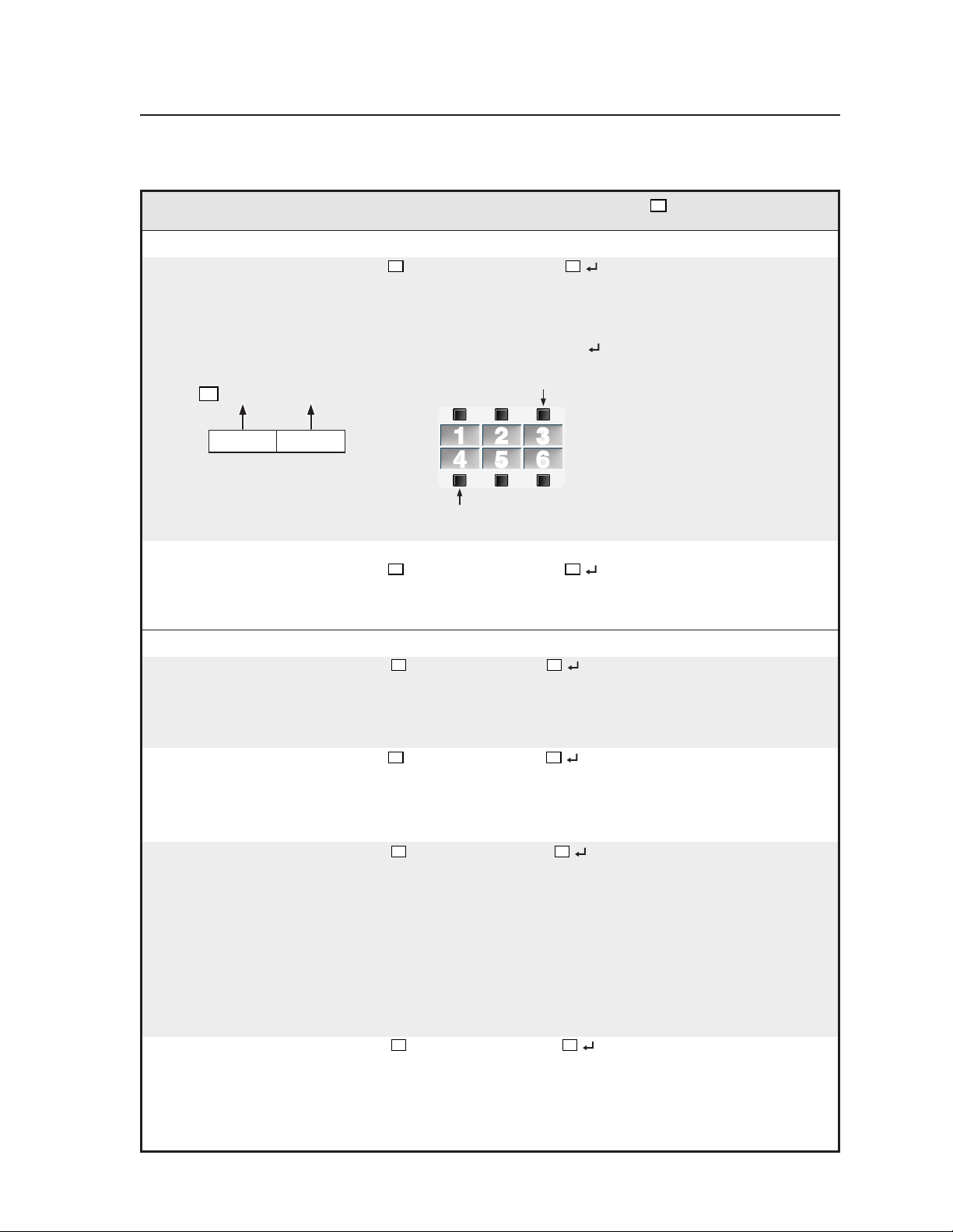
Command/response table for special function SIS commands, continued
Command ASCII Command Response
X?
values
(host to MLC) (MLC to host) and additional descriptions
IRCM-DV+ address 2, address 1 button association
Associate MLC buttons w/IRCM-DV+ 25* X? # DVA_VMap*
X?
Associate specific MLC buttons
with the VCR and DVD halves
of the IRCM-DV+ which has
DIP switch-based addresses of 1
and 2.
Example: 25*52# DVA_VMap*052 Associate MLC button 4 with
IRCM-DV+ address 1 (DVD
functions) and
MLC button 3 with IRCM-DV+
= (3 x 16) + (4) = 52
X?
The VCR half of the IRCM-DV+
will be associated with button 3.
address 2 (VCR functions). See
the illustration.
3
Button to
associate the
VCR half
(even address,
2 or 4) with
4
Button to
associate the
DVD half
(odd address,
1 or 3) with
The DVD half of the IRCM-DV+
will be associated with button 4.
123
456
IRCM-DV+ address 4, address 3 association
Associate MLC buttons w/IRCM-DV+ 26* X? # DVB_VMap*
X?
Associate MLC buttons with the
VCR & DVD parts of an
IRCM-DV+ which has DIP
switch-set addresses of 3 and 4.
Miscellaneous settings
Automatic shut-off 15 * X? # AutoOff*
(Issue a display power-off (default),
command after a specific 1 = 15 minute shutoff delay,
period of inactivity.) 2 = 30 minute delay,
Automatic on 27* X? # AutoOn*
(Send a display power-on not sent when an MLC input
command when any MLC selection button is pressed.
input selection button is pressed.) 1 = on: pressing an MLC input
Set switch exclusion 20 * X? # SwtMode*
Each of the MLC’s six input selection
buttons can be disabled for switching
between inputs. If the MLC does not
have a switcher set as a peripheral to it,
and the projector has only three
inputs, for example, you may wish to
exclude from the switching rotation
the excess input selection buttons
(buttons 4-6). Each excluded button
can still have an RS-232 or IR
command or a relay associated with
it, but pressing an excluded button
will not cause any input switching to
occur.
Set power-down button hold to off 22 * X? # PwrOffDly*
The Display Power Off button’s twosecond press and hold period can be
changed, via HyperTerminal only, to
zero seconds.
X?
X?
X?
0 = disabled (use manual shutoff)
... in 15 minute steps up to
32 = 480 minutes (8 hours).
0 = off: a power-on command is
selection button causes a
power-on command to be sent.
Set the (6 bit, binary) address
(0-63) of the MLC’s input selection
buttons that will not be used for
input switching.
Examples:
0 = all six buttons are included in
the switching rotation.
1 = exclude input selection button 1
(upper left).
32 = exclude input selection button 6
(lower right).
56 = exclude buttons 4-6.
63 = no buttons are included for
switching.
X?
0 = the MLC requires a 2-second
delay (Display Power button
hold period) to start power-off
sequences (default).
1 = the MLC needs no delay (the
button hold period is 0).
4-7MediaLink Controllers • Serial Communication
Page 40

Serial Communication, cont’d
Command/response table for advanced instructions
(for the Windows-based control program)
Data downloads/uploads are initiated by sending a series of hex commands to the
host RS-232 port of the MLC. The Windows-based control program uses these
commands mainly to load and save driver data and system configuration settings.
Command Hex. command Response Additional description
(host to MLC) (MLC to host)
Send/receive data to/from page 0 memory
Send 80 A0 [16k bytes of data] Dnl0 The host downloads 16k bytes
of binary data to page 0 of the
MLC’s memory.
Receive 80 A1 The MLC sends 16k bytes of
binary data to the host.
Send/receive data to/from page 1 memory
Send 80 A2 [16k bytes of data] Dnl1 The host downloads 16k bytes of binary
data to page 1 of the MLC’s memory.
Receive 80 A3 The MLC sends 16k bytes of
binary data to the host.
Send/receive a segment (256 bytes) of data (a segment relating to a single button)
Send 80 A6 ?? [256 bytes of data] Seg0 The host sends 256 bytes of
binary data to the MLC.
Receive 80 A7
??
The MLC sends 256 bytes of
binary data to the host.
Initiate or abort IR learning
Learn ready 80 B0
Abort learning 80 B1 Lrn Abort Abort IR learning.
??
LrnRdy Initiate IR learning.
LrnTimOut Timeout during IR learning.
LrnRetry Retry IR learning. (Aim remote
control at MLC, press button again.)
LrnFail IR learning has failed.
LrnOK IR learning has succeeded.
Set pass-through/normal mode
Set to pass-through mode 80 C0 Hst1 Set the MLC to RS-232 pass-
through mode. RS-232 commands
will go directly to a connected
Extron MLS switcher for direct
control of switcher settings.
Set to normal mode 80 C1 Hst0 Set/reset the MLC to normal
mode. RS-232 commands are
processed by the MLC.
Activate a memory block (segment)/emulate a button press
Activate a block 80 D0
Emulate a button press 80 D1
??
??
??
indicates the block number in hex notation where ?? can be 0 to 7F (hex)
(0 to 127 decimal).
??d
??d
IRSnd*
??d
Btn
Activate/trigger a memory
block. (Send the command
stored at that address).
Simulate pressing a button.
(Send the command and/or
perform the function [relay
triggering] stored in the block.)
indicates the block number in ASCII numeric notation.
The responses shown are ASCII.
MediaLink Controllers • Serial Communication4-8
Page 41

Control Software for Windows
The included Extron MediaLink™ Control Program for Windows offers another way
to control the MLC via RS-232 connection in addition to the Simple Instruction Set
commands. The control program’s graphical interface includes the same functions
as those on the switcher’s front panel and some additional features that are only
available through the Windows-based software.
The control software must be used in order to download projector driver files into
the MLC controller.
The control software is compatible with Windows 95/98, Windows NT, and
Windows 2000. Extron’s MediaLink Control Program is included with the MLC,
and updates can be downloaded from the Extron Web site
(http://www.extron.com).
Installing the software
The control program is contained on a set of 3.5-inch diskettes, and it requires
approximately 2 MB (megabytes) of hard disk space.
To install the software on the hard drive:
1. Run SETUP.EXE from the floppy disk.
2. Follow the instructions that appear on the screen.
By default the installation creates a C:\MediaLnk directory, and it places two icons
(MediaLnk Control Pgm and MediaLnk Help) into a group or folder named
“Extron Electronics”.
®
™
Using the control program
Many items found in the MediaLink Control Program are also accessible via front
panel controls and the LCD menus described in chapters two and three. Refer to
those chapters for details on features and settings. The MediaLink Help Program
provides information on settings and on how to use the control program itself.
Some features, including the miscellaneous options, are only available via this
control program. These features are described in the sections of this chapter that
correspond to the parts of the control program where the features are found.
1. To run the control program, double-click on the MediaLnk Control Pgm icon
in the Extron Electronics group or folder. The Comm menu
appears on the screen.
2. Click on the comm port that is connected to the MLC’s RS-232 port.
The Extron MediaLink Control Program windows appear. The projector
driver, port, and firmware information are displayed at the bottom of the
screen. There are several views available: the User Mode screen, the Switcher
(MLS) Config. screen, the Controller (MLC) Config. screen, the Advanced
Projector Config. screen, and the Relay & Misc. Options screen.
4-9MediaLink Controllers • Serial Communication
Page 42

Serial Communication, cont’d
User Mode
The User Mode screen, shown below, includes the most frequently used controls: it
emulates the MLC 206 front panel for primary mode functions (input selection,
projector power control, volume control, relay toggling), and it emulates the
MediaLink Control Modules. See chapter two of this manual and refer to the
MediaLink™ Control Modules User’s Manual for details on basic operation.
When an MLC is connected to the host computer, projector driver and MLC
firmware information is available at the bottom of every screen within the control
program. The projector driver name and version appear in the two spaces on the
left, and the third space shows which port is used for the host-to-MLC connection.
The fourth space indicates the MLC’s firmware version.
Special features
Relay buttons — By clicking on one of the Relay buttons you can trigger the
corresponding relay (1, 2, or 3) independently from selecting an input or
toggling another button.
Clicking on a Relay button triggers a latching on or off relay response
regardless of how the relays are configured (latching or momentary) in the
Relay & Misc. Options screen.
Volume Mute — Check this box to activate the audio mute (1Z, 0Z) command.
Disable Switcher Front Panel Menus — This feature toggles the executive mode
on or off to prevent or allow configuration (menu-based) changes via the
front panel of an optional MediaLink Switcher.
MediaLink Controllers • Serial Communication4-10
Page 43

Switcher (MLS) Config
The Switcher (MLS) Config screen, shown below, only becomes available if an
optional MediaLink Switcher is connected to the MLC. It allows you to make
switcher-specific adjustments without having to use the switcher’s front panel
controls.
In this part of the program you can:
• Set per-input audio adjustments (level, bass, treble).
• Set overall volume. (Selecting Mute selects audio input 0.)
• Set the left-right audio balance.
• Set the mixer volume (MLS 506MA & MLS 506SA only).
• Choose between stereo and mono output for the variable preamp output.
• Tell the switcher whether a 4 ohm or an 8 ohm (the total resistance of the
connected speakers) load is connected to the amplified output.
• Set the video format (composite video/S-video, or component video) for inputs
1 through 3 (MLS 506MA & MLS 506SA only).
• Set the RGB delay period (for Triple-Action Switching).
• Reset the switcher to factory default settings. This resets all switcher settings and
options.
Not all of the features shown above will appear for every model of MLS
switcher.
4-11MediaLink Controllers • Serial Communication
Page 44
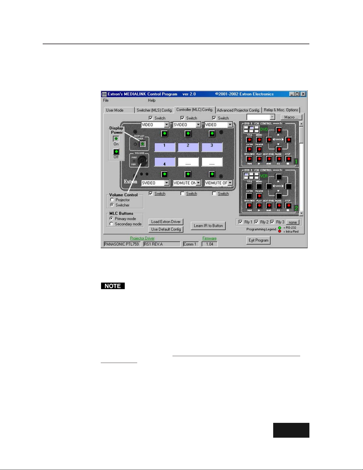
Serial Communication, cont’d
Controller (MLC) Config
The Controller (MLC) Config screen, shown below, is the most important part of the
MediaLink Control Program. This is where you configure the controller and the
control modules, and initiate IR learning.
A green dot in the middle of a button indicates that RS-232 codes have been
associated with that button. A red dot indicates that IR codes are associated with/
learned for that button. If the button is grey or black, there is no code stored in that
button’s memory slot.
We recommend using RS-232 for communicating with a display device.
The check boxes above/below the input selection button menus indicate whether
the button is part of the switching rotation (checked, pressing the button causes
that input channel to be selected) or not (unchecked, pressing the button does not
cause an input switch). A button’s Switch box should be unchecked if that button
will be used for something other than selecting an input – issuing special function
commands such as auto image or zoom, for example.
To see if a relay is associated with a button, select the button, and look at the relay
area in the lower right of the screen: the box for a given relay will be checked if it is
associated with that button.
display button at a time, though two or three relays can be associated with the
same button. Relays cannot be tied to buttons in secondary mode.
Load Extron Driver
This option lets you download a control file (library) of Extron-created projector
commands that are specific to a particular projector. Pre-configured control files
(drivers) should be used whenever possible. If no driver is available for the display
you want to control, it is possible to create your own via IR learning.
Use Default Config
This feature lets you select and use the MLC default configuration
for that projector. See the MediaLink Help program for details.
Each relay can only be associated with one input or
MediaLink Controllers • Serial Communication4-12
Page 45

Primary and secondary modes
The MLC Buttons area in the lower left of this screen lets you select between primary
and secondary modes. A button can have one code stored in its memory for
primary mode, and another code stored
for secondary mode. In each mode the
MLC’s buttons can be given an on-screen
label: select an option from the pull-down
menu above/below each button, as
shown at right. If desired, you can change
the label name during IR Learning or in
the Advanced Projector Config screen. In
normal use (primary mode), the MLC will
issue commands from its primary
memory blocks. Secondary mode is
typically reserved for special commands
such as auto adjust and zoom.
Display Power on/off
If you select Display Power, a dialog box appears in which you can select Power On
or Power Off so that the corresponding IR commands can be “learned” from the
projector’s remote control.
If the projector’s remote
control has just one
button for on/off
toggling, you must
“learn” that same
command to each button
(Display Power On,
Display Power Off).
Volume control settings
The MLC can control the audio volume adjustment of either an optional MediaLink
Switcher (MLS) or the projector.
Select Projector if you plan to use the projector/plasma display’s speakers or if you
plan to use the projector/plasma display as a preamp. Select Switcher if you plan
to use an external switcher as an audio preamp or amplifier.
If you select Projector, the Volume
Adjust dialog box appears, in
which you can select Up or Down
or Mute or Unmute so that the
corresponding IR commands can
be “learned” from the projector’s
remote control for controlling
these functions.
If you select Switcher, the MLC
will automatically issue the
necessary volume up/down
commands via the MLS/Power
port.
4-13MediaLink Controllers • Serial Communication
Page 46

Serial Communication, cont’d
IR learning
The MLC can “learn” commands in order to control the projector or to control devices
such as VCRs, audio tape players, or DVD players. For the MLC 206, IR learning is
only necessary if there are no RS-232 codes available for that projector or if you
need to customize the driver. For the infrared control modules, IR learning is
essential for setting up the buttons so you can control the VCR, DVD player or
other device.
To initiate IR learning,
1. Attach cables between the MLC 206 and any optional IR control modules, and
connect an RS-232 cable between the MLC’s config port and the host computer.
Refer to the Control Modules User’s Manual and other accessories’ manuals for
details.
2. If you haven’t already done so, connect the MLC 206 to a 12VDC power
supply, turn on the computer, start the MediaLink Control Program, and
select the Controller (MLC) Config screen.
3. Select the button (an MLC button, or a button on an optional control module)
and mode (MLC primary/secondary) for which you want the MLC to learn
IR codes.
4. Click on the button labeled “Learn IR to Button”. As shown below, a dialog
box appears that indicates the button to which IR codes will be learned, and
to allow you to OK or cancel the IR learning process.
5. When you are ready to
start, click on the OK
button. A Status of IR
Learning message area
appears beneath the
picture of the MLC.
6. Follow the onscreen directions.
A sampling of the
messages and
directions that
appear on screen
are shown below.
DISPLAY
POWER
VCR DVD Laptop
VOLUME
MAX/
MIN
Extron
1 2 3
4 5 6
7 809
Aim the remote
control at the MLC's
IR pickup devices,
press the remote's
button, follow on-
screen prompts.
MLC 206
4"–14"
(10 – 36 cm)
MLC 206
MediaLink Controller
OR
MediaLink Controllers • Serial Communication4-14
Page 47

During IR learning hold the device’s remote control 4” to 14” (10 cm to 36 cm)
away from and directly in front of the MLC’s IR pickup device. You may
need to experiment to determine the best IR learning distance for each remote
control.
Once the IR
commands have been
successfully learned,
you will have the
opportunity to accept
a default label or type
in your own label
(which will appear in
the control program
screens) for that
button.
10. Repeat steps 6 through 9 for each button hat you want to set up with IR codes.
Associating IRCM-DV+ modules with MLC inputs
If an optional IRCM-DV+ control module is to be used with the MLC, you must
associate each half (DVD and VCR) of the module with a different MLC input
selection button. That way the MLC knows which half of the module to activate
when the appropriate MLC input button is pressed. MLC button association also
tells the IRCM-DV+ whether to send DVD commands or VCR commands, allowing
you to activate and use the IRCM-DV+ from the front panel buttons in addition to
RS-232 control.
When an IRCM-DV+ is connected to the MLC, two
pictures of the module appear on the right side of
the Controller (MLC) Config screen, as shown at
right. The upper picture represents the DVD half,
the lower one represents the VCR half.
A simplified representation
of the MLC’s input selection
buttons appears at the top
of the picture of each half of
the module. Associate an
Extron
DISPLAY
POWER
VOLUME
MAX/
MIN
123
456
MediaLink Controller
MLC 206
MLC input button with
each half of the IRCM-DV+ by doing the following:
1. In the picture of the DVD half of the
IRCM-DV+, select (click on) a miniaturized
MLC button to associate the DVD controls
with.
2. In the picture of the VCR half of the IRCM-DV+, select (click on) a different
miniaturized MLC button.
You cannot select the same MLC input selection button for both halves of the
IRCM-DV+.
3. Perform IR learning for the buttons in each half of the control module, if
needed.
4-15MediaLink Controllers • Serial Communication
Page 48
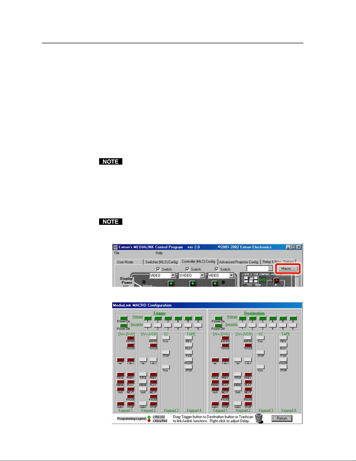
Serial Communication, cont’d
Macros: associating MLC and control module buttons with each other
Basic configuration, covered in the rest of this chapter, will meet your needs for
most installations. In a standard installation a single control command is sent each
time an MLC front panel button (in primary or secondary mode) or control module
button is pressed, or the Volume knob is turned. Pressing an input selection button
also causes a channel change (input X to input Y). Additionally an extra command
(such as repeat power-off) can be sent out during the display power-on or poweroff period if set up to do so via the Relay & Misc. Options part of the control
program.
With a more complex setup you can simultaneously control more things. The
Macro feature of the MediaLink Control Program (version 2.0 and higher) provides
a way to associate MLC/control module buttons with each other. Once two
buttons are associated, you can press one button to trigger it’s own functions, and
also trigger all the commands associated with the other button.
The MLC must contain firmware of version 1.05 or higher in order to support
macros.
Follow these steps to set up button associations by using the Macro feature of the
MediaLink Control Program:
1. Cable and power on the MLC and connected control modules.
2. If needed, load a projector driver into the MLC, and perform IR learning for
MLC and IRCM control module buttons.
Only buttons that have been configured with IR or RS-232 codes can be used
as macro triggers.
3. Click on the Macro... button in the Controller (MLC) Config. screen.
The Macro Configuration screen appears:
MediaLink Controllers • Serial Communication4-16
Page 49

4. Select a “trigger” button that has been programmed with IR code (shown in
dull red) or RS-232 code (shown in green). This is the button you want to
push to trigger both button’s commands. Hold the mouse button down as
you drag the trigger button across the screen to the desired “destination”
button, then release it.
The selected trigger and destination buttons turn yellow, and both buttons
display the number of the destination button. (After you finish the next step,
let your cursor hover over the trigger button to get a more straightforward
note about the button settings.)
5. Select the length of delay that will occur between when the trigger button’s
commands are sent and when the destination button’s commands are sent.
4-17MediaLink Controllers • Serial Communication
Page 50

Serial Communication, cont’d
The trigger and destination buttons change to lighter shades of green or red
once they have been associated with each other.
Tied buttons can be identified by their lighter shade of red or green, and by the
destination button number displayed on the tied trigger and destination
buttons. In the example above, pressing the MLC’s input button 1 will also
cause the VCR Play command to be issued.
Relays associated with a destination button will not be executed when the
trigger button is pressed.
6. Repeat steps 4 and 5 for all desired pairs of trigger and “destination” buttons.
7. To
remove (undo) a tie, click on and drag the trigger button to the trashcan,
then release the button and confirm the unlinking.
MediaLink Controllers • Serial Communication4-18
Page 51

8. You can daisy chain trigger-destination ties together to allow multiple control
commands to be sent as a result of one button press. For example, you could
tie the PowerOn button to the TV/VCR button of a DVD control module 1,
and then tie the DVD TV/VCR button to the TV/VCR button of a VCR
control module 2, as shown in this example:
1
2
Now when someone presses the PowerOn button, the projector and the DVD
player and VCR will all be sent commands to prepare them for use.
If a daisy chain of button ties has been set up, pressing a tied button will cause
commands to be sent out for only the ties made from the pressed button to
subsequent buttons in the daisy chain. Button presses do not affect buttons
that come earlier in the daisy chain. Also, input changes and relays will be
executed only for the pressed button, not for other buttons in the linking chain.
In the above example if you press the button that controls the DVD’s TV/VCR
function, the DVD’s TV/VCR function and the VCR’s TV/VCR function (the
second link of the daisy chain) will be executed, but the display power-on/-off
commands will not be executed (the first link of the daisy chain is not affected).
9. To exit the Macro screen and return to the Controller (MLC) Config part of the
control program, click on the Return button in the lower right corner of the
screen.
4-19MediaLink Controllers • Serial Communication
Page 52

Serial Communication, cont’d
Advanced Projector Config
The Advanced Projector Config screen, shown below, provides a way to check the
kind, length, and location of codes (IR/RS-232), if any, that are stored in the
memories for the various MLC and control module buttons. In this screen you can
also edit or enter RS-232 codes, define step parameters for controlling a projector’s
audio volume, and change the name of the projector driver.
In this area of the IR/232 params section, you can edit or replace button label text.
The “radio buttons” across the top of this screen–MLC (Pri), MLC (Sec), CM 1,
CM 2, CM 3, CM 4–let you select a different mode of the MLC or select one of the
control modules. The buttons shown on the screen change as you select different
modes or control modules: the pictures below show how the upper portion of the
screen looks when an IRCM-VCR (CM 2 in this case) or an IRCM-DVD+ (CM 3 for
this example) is selected.
The power polling feature allows the MLC to regularly ask the projector whether it
is on (fully powered up) or off (in standby mode), and to determine the status by
comparing the projector’s reply with expected responses.
Not every projector supports RS-232 power polling. Also, not every Extroncreated projector driver supports power polling.
You do not need to alter the power polling feature if Extron has already created a
driver for your projector. If there is not Extron-created driver for your projector,
select MLC (Pri), then select Power Polling. Three more buttons appear, as shown
below. Refer to your projector’s user’s manual to find the RS-232 command strings
MediaLink Controllers • Serial Communication4-20
Page 53

to use for asking for the power status (the polling command), the off reference
response (for Off Compare), and the on reference response (for On Compare).
Refer to the control program’s help file for step-by-step programming instructions.
For power polling to be used, you must also select (check) the “Use Projectorpower Polling” box in the Misc. Options part of the Relay & Misc Options
portion of the control program (shown on page 4-22).
If a projector driver does not already exist for your projector, and the projector
requires discrete audio volume commands (for each percent of maximum volume,
for example), as opposed to a pair of volume up/down commands, you can
program those commands in the Volume Table section.
Use the volume table only if you plan to use the display device’s audio inputs.
For the MLC primary mode, select the Volume Table button to access to slider bars
and boxes where you can set volume adjustment step parameters. If you select the
Tools button, a menu (shown in the picture below) appears that provides ways to
make setting up the projector volume table easier.
Follow these procedures to add a new volume table:
1. Set the total number of steps in the Total Steps scrollbar.
2. Follow the step-by-step details provided in the help file to create an RS-232
command string for “step 1” (the first increment of volume change).
3. Click on the Tools button. If most steps for volume increments have similar
RS-232 codes, select “Fill table w/ copies of step 1”. That process copies the
command string you entered in step two into all the subsequent steps.
4-21MediaLink Controllers • Serial Communication
Page 54

Serial Communication, cont’d
4. Select “step 2” by using the Current Step scrollbar or box, then edit the RS-232
string as needed to customize it for the next volume command.
5. Repeat step 4 for each “step” in the volume table.
6. The Exit Program button in the lower right corner of the screen is replaced by
the Cancel and Take buttons. To save the changes,
click on Take. To ignore the changes, click on Cancel.
The Remove IR/232 feature lets you erase the code that has been stored for the
selected button.
For additional details on using the features of the Advanced Projector Config screen,
refer to the MediaLink Help file.
Relay & Misc. Options
The Relay & Misc. Options screen, shown below, includes an assortment of settings
including those pertaining to the projector, relays, audio volume, and resetting the
memories to factory defaults.
When a change has been made to various items in the Relay & Misc. Options
screen, the Exit Program button in the lower right corner of the screen is replaced
by the Cancel and Take buttons. To save the changes,
click on Take. To ignore the changes, click on Cancel.
Special features
Relay __ Mode — Each of these areas shows the settings for a particular relay and
what MLC or Control Module button it is associated with, if any.
Tied to Btn __ — If this feature is enabled, the relay turns on/off when the
specified button is pressed/activated. You can disable a button tie by
unchecking this box. To tie a relay to a button, select the button from
within the Controller (MLC) Config screen, then select the appropriate
relay. Each relay can be tied to only one button, but more than one relay
can be tied to the same button.
MediaLink Controllers • Serial Communication4-22
Page 55

Latched/Momentary — Contacts can be programmed to operate in one of
two ways: latching (brief contact) (press to turn on, press to turn off), or
momentary (timed) (press to turn on, timeout to turn off). If you select
Momentary, you can set the timeout period by using the slider bar.
NC (open), NO (closed) — Select the appropriate box to make the relay
normally closed or normally open.
Projector Comm — In this area you can set the communications protocol (baud
rate, parity, data bits) that is required by the projector.
Misc. Options — This section provides a way to send (or not send) commands
while the display is off or powering down or powering up, to mute/unmute
MLS switcher or projector audio, and to repeat power-down commands. If
the Repeat Power-Down box is checked and IR codes are stored for the
power-down command, the MLC will send out IR power-down codes twice.
For MLCs that have firmware version 1.04 and higher, if the Auto Onbox is
checked, the MLC sends a display power-on command when any MLC front
panel button is pressed.
Limit initial power-up volume — Here you can specify an attenuation level for the
initial audio volume when the display is powered on. If the Limit initial
power-up volume box is not checked (not enabled) or if the limit is set to
100%, the volume will not be limited (attenuated) when the projector/
switcher turns on.
Auto shutoff — If Auto shutoff is enabled, the controller monitors the time elapsed
since the last button press or knob rotation and sends a display power off
command (or that command and any other commands associated with the
Display Power button) after a set period of inactivity. That period can be
selected in fifteen-minute increments to be as long as 480 minutes (8 hours).
Reset to Factory Defaults —
Total Factory Reset (MLC + MLS)! is a global system reset that clears
settings (including audio adjustments and IR and RS-232 commands and
drivers) in both the MLC and in an attached MLS switcher.
To reset the switcher only, manually press and hold the Menu and Next
keys on the front panel while connecting the switcher to an AC power
source.
Total Factory Reset (MLC only)! is a global reset that clears
(including button configuration and IR and RS-232 commands and
drivers) in the MLC only. This does not affect the settings and
adjustments that are specific to an MLS switcher (audio adjustments, for
example).
Projector Volume Options —
Rate refers to the speed at which volume control commands are sent to the
projector or switcher. The fastest command-sending rate is 0, the slowest is 3.
If the MLC is set to control the projector’s audio volume instead of controlling
a MediaLink Switcher’s volume, select the settings here that match the
projector’s volume control settings. Some projectors use increment/
decrement commands to change the volume, some use a table of
predetermined levels. If the projector uses the table method of adjusting
volume, the number of steps used for volume adjustment is indicated in the
lower right corner. Refer to the projector’s manual or the display driver setup
document for details.
all settings
all
4-23MediaLink Controllers • Serial Communication
Page 56

Serial Communication, cont’d
Saving and restoring configurations
The MLC can be configured by various means (IR learning, downloading, or
combinations of those methods), and the configuration settings can be saved to a
file for later use.
1. In the MediaLink Control Program, select File, then select Save Configuration
as... .
2. Save the file as (filename).MLK. An unlimited number of configuration files
can be saved as long as each file has a unique file name ending in .MLK.
3. To retrieve the configuration from within the MediaLink Control Program,
select File, then select Restore Configuration from... . A set of all the
controller, switcher, and audio adjustment settings, and also drivers will be
downloaded into the MLC.
Using the help program
For information on program features, press the F1 computer key, or click on the
Help menu from within the MediaLink control program, or doubleclick on the MediaLnk Help icon in the Extron Electronics group or
folder.
For explanations of buttons or functions, click on the tabs in the help screen to
reach the desired screen. Use a mouse or the Tab and Enter keys to select a button/
function. A description and tips on using the program will appear on screen.
Downloading and using projector drivers
The MLC must be set up (configured) before it can control other equipment. Extron
provides preset configurations in the form of projector driver files. Projector
drivers assign projector commands to the MLC’s front panel controls so that
display power and other functions can be used to control the projector.
The most recent projector driver files are available at the Extron Web site at
http://www.extron.com. To download files to computer, do the following:
1. From the Extron Web site, select Download, then select MLC 206 from the list
of products.
2. Select Software and Drivers, then click on MediaLink Projector Drivers.
3. In the Description column in the list of projectors, select and click on the
model of projector for which a driver is needed.
4. Follow the instructions that appear on screen.
5. If the projector driver has been successfully downloaded, the projector driver
will be displayed in the Windows-based control program. It will also appear
in the list of available projector drivers when Load New Extron Driver From...
is selected from the control program’s File menu.
To view the settings and commands in each projector driver file without loading
the driver into the MLC, run the MediaLnk control software in emulation mode.
1. On opening the control program select Emulate instead of one of the comm
ports.
2. Select and double-click on the desired projector driver in the
(drive):\MediaLink\drivers folder.
To load projector drivers into the MLC, do the following:
1. Upon opening the control program, select and double-click on a comm port.
2. Select the File pulldown menu.
3. Select Load New Extron Driver from... and choose the appropriate driver.
MediaLink Controllers • Serial Communication4-24
Page 57

Key to file names
File name Description
________.MLL Extron-supplied projector driver library files. These files contain
________.MLK User-saved MLC/MLC-MLS/MLS configuration file. This
commands and settings pertinent to a particular projector.
includes adjustments/settings and whatever driver (if any) was
installed in the MLC at the time the file was saved.
4-25MediaLink Controllers • Serial Communication
Page 58

Serial Communication, cont’d
Using the emulation mode
The MediaLink Control Program features an emulation mode so you can set up a
MediaLink system before equipment is available on site. In emulation mode a
MediaLink Controller is always included in the system. You select which (if any)
MLS switcher and which control modules (if used) will be connected to the MLC.
You can save the emulated settings to a configuration file, then load that
configuration file to the MLC when equipment is available.
1. Start the control program. In the Comm Port Selection
screen, click on the Emulate radio button, then click on
OK. The Initialize Emulated MediaLink Configuration
from... dialog box appears.
3. You can create a new configuration starting from the
default settings (see 3a), or you can base the
configuration on an existing setup (see 3b).
3a. If you will be creating a brand new configuration,
select Cancel (as shown below)
emulated system will start out with the MLC and MLS default settings.
instead of following step 3b. The
3b. Alternatively, to create a configuration based on an existing (previously
saved) configuration file, select the appropriate configuration (___.MLK)
file.
The Save Emulated MediaLink Configuration as... dialog box appears.
MediaLink Controllers • Serial Communication4-26
Page 59

4. Enter a filename of your choice for storing the configuration settings, then
select Save.
The Emulation Configuration dialog box appears, as shown below.
5. Select the MediaLink equipment that will be part of the system you want to
configure, then click on OK. The Extron MediaLink Control Program
windows appear.
6. Select the desired settings in each section of the program.
In emulation mode you cannot perform IR learning. You must have an MLC
connected to the host computer for IR learning.
7. To save the configuration for future use, follow steps 1 and 2 in “Saving and
restoring configurations” on page 4-23.
4-27MediaLink Controllers • Serial Communication
Page 60

Serial Communication, cont’d
MediaLink Controllers • Serial Communication4-28
Page 61

MediaLink™ Controllers
Appendix A
A
Specifications, Part Numbers,
and Accessories
Specifications
Part Numbers and Accessories
Page 62

Specifications, Part Numbers, Accessories
Specifications
Control/remote — controller
Serial control port ........................ RS-232, 9-pin female D connector
Baud rate and protocol ............... 9600, 8-bit, 1 stop bit, no parity
Serial control pin configurations 2 = TX, 3 = RX, 5 = GND
Peripheral switcher control port ........ (1) 3.5 mm direct insertion captive screw connector, 4 pole
Program control ........................... Extron’s control program for Windows®
Extron’s Simple Instruction Set™ – SIS™
Control — room relays
Number/type ............................... 3 momentary or latching (configurable via control software)
Connectors .................................... (1) 3.5 mm direct insertion captive screw connector, 6 pole
Contact rating ............................... 24V, 1 A
Control — projector/source
Display/source control port (IR) (1) 3.5 mm direct insertion captive screw connector, 5 pole
(also used for IRCM control)
Display/source control port (RS-232) (1) 3.5 mm direct insertion captive screw connector, 5 pole
IR learning frequencies ............... 30 kHz to 62 kHz
IR learning distance ..................... 4” (10 cm) to 14” (36 cm) from the MLC’s faceplate
General
Power............................................. 12VDC, 0.38 A from an optional MediaLink Switcher (MLS) or the included
100VAC to 240VAC, 50/60 Hz, external, autoswitchable, 12VDC, 1 A max.
power supply.
Temperature/humidity .............. Storage -40° to +158°F (-40° to +70°C) / 10% to 90%, non-condensing
Operating +32° to +122°F (0° to +50°C) / 10% to 90%, non-condensing
Rack mount................................... Yes, with optional MLM-RAAP rack mounting kit; also furniture or wall-
mountable
Enclosure type.............................. Metal
Enclosure dimensions
MLC 206 faceplate ........... 4.5" H x 6.4" W x 0.1” D (11.4 cm H x 16.3 cm W x 0.3 cm D) (3 gang)
MLC 206 EC faceplate ..... 3.2” H x 6.3” W x 0.1” D (8.1 cm H x 16.0 cm W x 0.3 cm D)
MLC 206 AAP EC faceplate 3.2” H x 9.8” W x 0.1” D (8.1 cm H x 24.9 cm W x 0.3 cm D)
MLC 206 AAP faceplate . 4.5” H x 10.1” W x 0.1” D (11.4 cm H x 25.7 cm W x 0.3 cm D) (5 gang)
Controller (all models) .... 2.75" H x 5.25" W x 1.2" D (fits in a 3 gang box)
(7.0 cm H x 13.3 cm W x 3.1 cm D)
(Depth excludes connectors and knobs. Allow at least 1.75” depth within
the wall or furniture.)
Product weight
MLC 206 ............................ 1.7 lbs (0.8 kg)
MLC 206 EC...................... 0.7 lbs (0.3 kg)
MLC 206 AAP EC ............ 0.7 lbs (0.3 kg)
MLC 206 AAP .................. 0.8 lbs (0.4 kg)
Shipping weight (all models)..... 6 lbs (2.7 kg)
Vibration ....................................... ISTA/NSTA 1A in carton (International Safe Transit Association)
Listings .......................................... UL, CUL
Compliances ................................. CE, FCC Class A, VCCI, AS/NZS, ICES
MTBF ............................................. 30,000 hours
Warranty ....................................... 3 years parts and labor
Specifications are subject to change without notice.
MediaLink Controllers • Specifications, Part Numbers, AccessoriesA-2
(7.4x-082202-D3x
)
Page 63
Part Numbers and Accessories
Included parts
These items are included in each order for an MLC 206 controller:
Included parts Replacement
MLC 206 (3-gang) (gray, black, white) 60-385-01, -02, -03
or
MLC 206 AAP (5-gang) (gray, black, white) 60-460-01, -02, -03
or
MLC 206 EC (white) 60-385-10
or
MLC 206 AAP EC (white) 60-460-10
IR Emitter
12VDC, 1 A power supply kit 70-055-01
IEC power cord
UC 50’ (15 m) universal projector control cable 26-518-01
9-pin male-to-male gender changer 10-438-01
Electrostatic discharge grounding kit
Tweeker (small screwdriver)
MLC input selection window labels (text) 33-618-01
MLC input selection window labels (text, symbols) 33-750-01
MLC input selection window labels (symbols) 33-751-01
MLC display power/audio volume symbol label
(gray or black or white) 33-793-01, -02, -03
MediaLink Controllers User’s Manual
Windows-based MediaLink control software
MLC 206 Quick Start Guide 68-627-01
part number
Accessories
These items can be ordered separately:
Mounting hardware Part number
Three-gang mud ring/mounting bracket
Three-gang EWB external wall box (gray, black, white) 60-454-01, -02, -03
Five-gang EWB external wall box (gray, black, white) 60-456-01, -02, -03
10X8 EWB external wall box
Faceplates Part number
MLM-5GWP (gray, black, white) 60-407-01, -02, -03
MLM-10X8P (gray, black, white) 60-392-01, -02, -03
MLM-RAAP (gray, black) 60-391-01, -02
MLM-L (gray, black, white) 60-387-01, -02, -03
MLM-LAAP (gray, black, white) 60-389-01, -02, -03
(gray, white, black) 70-086-02, -12, -22
(gray, black, white) 60-457-01, -02, -03
A-3MediaLink Controllers • Specifications, Part Numbers, Accessories
Page 64

Specifications, Part Numbers, Accessories, cont’d
Miscellaneous accessories Part number
MLA-Remote IR remote control 70-154-01
IR Link IR signal repeater (gray, black, white) 60-404-01, -02, -03
IR Broadcaster 60-272-01
Current/display power sensor 60-271-01
IRCM-VCR (gray, black, white) 70-148-01, -02, -03
IRCM-DVD (gray, black, white) 70-149-01, -02, -03
IRCM-DVD+ (gray, black, white) 70-179-01, -02, -03
IRCM-Tape (gray, black, white) 70-180-01, -02, -03
IRCM-DV+ (gray, black, white) 70-220-01, -02, -03
ACM-Tone (gray, black, white) 70-181-01, -02, -03
ACM-Level (gray, black, white) 70-182-01, -02, -03
RCM-SC (gray, black, white) 70-183-01, -02, -03
RCM-SCLT (gray, black, white) 70-184-01, -02, -03
AC Net AAP (gray, black, white) 70-150-01, -02, -03
Cables
These cables can be used for the RS-232 control connection between the MLC and
the projector:
Projector control cable Part number
UC 100’ (30 m) universal projector control cable 26-518-02
UC 200’ (61 m) universal projector control cable 26-518-03
This cable is recommended for connecting an MLC to a MediaLink Switcher and/
or to an IR Link or control modules such as IRCMs, ACMs, and RCMs:
Comm-link cable Part number
50 feet/15.2 meters long 26-461-01
100 feet/30.5 meters long 26-461-02
200 feet/61 meters long 26-461-03
400 feet/122 meters long 26-461-04
Bulk 500 feet/152.4 meters long 22-119-02
Bulk 1000 feet/304.8 meters long 22-119-03
MediaLink Controllers • Specifications, Part Numbers, AccessoriesA-4
Page 65

MediaLink™ Controllers
Appendix B
B
Dimensions, Templates,
Replacements, and Upgrades
Dimensions
Templates
Replacements and Upgrades
Page 66

Dimensions, Templates, Replacements, Upgrades
Dimensions
The following diagrams have been reduced to fit on the page. All dimensions are
given in inches. The symbol “ø“ indicates a diameter.
MLC 206 faceplate dimensions
MLC 206 AAP faceplate dimensions
MediaLink Controllers • Dimensions, Templates, Replacements, and UpgradesB-2
Page 67
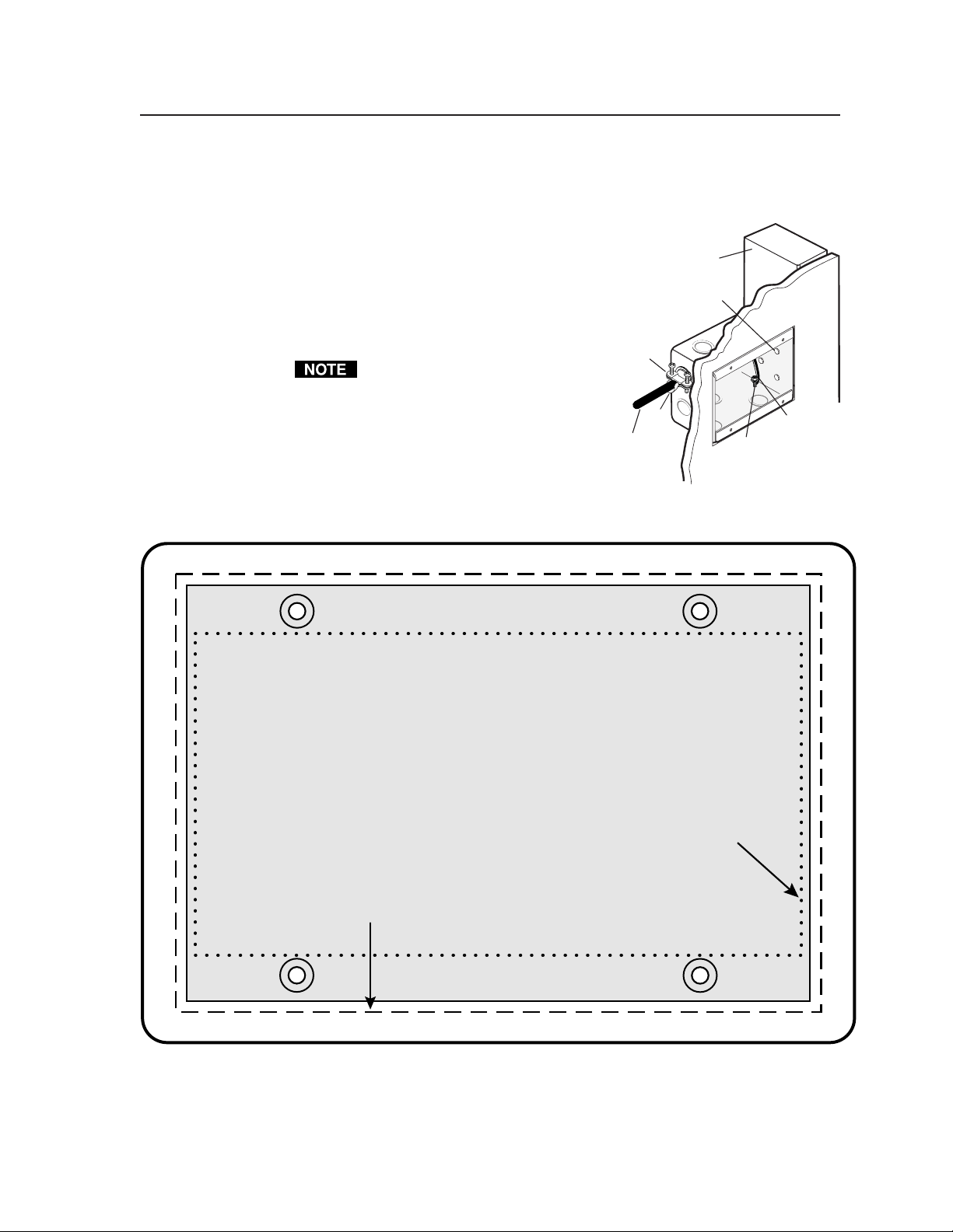
Templates
Use the full size template below (MLC 206) or on the next page (MLC 206 AAP) or
a 100% size photocopy of the template as a guide for cutting
a hole in a wall or furniture for installing the MLC. Cut
out the appropriate dashed or dotted inner rectangle of
the template, lay the template against the installation
Wall Stud
surface (wall/furniture), and mark the opening on
the surface.
Screws or Nails
The controller requires a depth of at least 1.25”
(3.2 cm) inside the wall or furniture.
Cable
Clamp
If you use a wall box or mud ring,
connect it to an earth ground. If you
do not use a grounded wall box or
mud ring, ground the faceplate to an
earth ground, or tie it to the circuit
ground via a ground pin on the
Foil
Shield
Installation
Cable
Screw
Braided
Shield
circuit board.
The light gray area represents the layout of the
electrical box (3.75"H x 5.6"W) against
the rear of the front panel.
To install the controller
The dashed line indicates the cut-out area
(3.95"H x 5.8"W) for installing
the electrical wall box.
without
a wall box,
use the cut-out area (2.9"H)
indicated by the dotted line.
B-3MediaLink Controllers • Dimensions, Templates, Replacements, and Upgrades
Page 68

Dimensions, Templates, Replacements, Upgrades, cont’d
the rear of the front panel.
To install the MLC 206 AAP
indicated by the dotted line.
directly into furniture, use the
cut-out area (2.8" H x 8.8" W)
the electrical wall box.
(3.9" H x 9.5" W) for installing
The dashed line indicates the cut-out area
electrical box (3.75" H x 9.3" W) against
The medium grey area represents the layout of the
MLC 206 AAP Cutout Template
line indicates the
with the solid grey
The light grey area
MediaLink Controllers • Dimensions, Templates, Replacements, and UpgradesB-4
location of the MLC
Page 69

Replacements and Upgrades
Firmware replacement
In some cases the MLC’s firmware may require replacement with an updated
version. We recommend that you send the unit in to Extron for service and
updates.
CAUTION
Changes to firmware must be performed by authorized service personnel
only.
Follow these steps to replace firmware in the MLC 206.
1. Disconnect the power supply from the power source.
To prevent electric shock, always unplug the MLC from the power source
before opening the enclosure.
2. Remove the MLC from the wall or furniture.
3. Remove the MLC’s rear cover.
A. Remove the five Philips head screws that fasten the rear cover to the
main part of the enclosure.
B. If applicable, disconnect the host computer’s RS-232 cable from the
MLC’s 9-pin Control connector.
C. Remove the two hex standoffs, which are on either side of the 9-pin
Control connector.
D. Lift the cover straight off the MLC.
Remove two hex screw connectors.
Lift cover straight up.
A
B
CDE A
IR
Display/Source Control
B
C
RS-232
D E
1A 1B 2A 2B 3A
3B
Relays IR/RCM
A
B
C
D
1 2 3 4 5 6
Tally Out
Extron Switcher Control
A B
MLS
/Power
USA
Printed in the
07 01
33-644-01 A
Remove five screws.
CAUTION
Do not touch any other electronic components inside the MLC. Doing so
could damage the MLC. Electrostatic discharge (ESD) can damage IC
chips even though you cannot feel it. You must be electrically grounded
before proceeding with firmware replacement. A grounding wrist strap is
recommended.
4. Locate the main controller firmware chip on the circuit board, and note which
end has the direction indicator notch, as shown in the following illustrations.
Notch
B-5MediaLink Controllers • Dimensions, Templates, Replacements, and Upgrades
Page 70

Dimensions, Templates, Replacements, Upgrades, cont’d
A
B
C D EA
IR
Display/Source Control
B C
RS-232
DE
1A
1B 2A
2B 3A
3B
Relays IR/RCM
A
B C
D
1
2
3 4
Tally Out
Extron Switcher Control
5
6
A
B
MLS
/Power
USA
Printed in the
07 01
33-644-01 A
Locating the firmware IC chip, and aligning the PLCC chip puller tool
with firmware chip slots
5. After you are electrically grounded, align the hooks of a PLCC IC puller tool
with the slots located in opposite ends of the firmware chip.
6. Insert the hooks into the slots, and squeeze the tool gently to grasp the chip.
7. Pull the chip straight out of the socket, and set it aside.
8. Align the notch on one end of the new firmware IC chip with the socket’s
notch indicator (in the same orientation as the old chip).
9. Gently but firmly press the chip into place in the socket.
10. Replace the MLC’s rear cover, and fasten it with the screws and hex standoffs
that were removed in step 3.
11. Re-mount the MLC, and reconnect the power supply to the power source.
Align Notches
Contact an Extron applications engineer if you need further assistance.
MediaLink Controllers • Dimensions, Templates, Replacements, and UpgradesB-6
Page 71

FCC Class A Notice
Note: This equipment has been tested and found to comply with the limits for a Class A digital
device, pursuant to part 15 of the FCC Rules. These limits are designed to provide reasonable
protection against harmful interference when the equipment is operated in a commercial
environment. This equipment generates, uses and can radiate radio frequency energy and, if not
installed and used in accordance with the instruction manual, may cause harmful interference to
radio communications. Operation of this equipment in a residential area is likely to cause harmful
interference, in which case the user will be required to correct the interference at his own expense.
Note: This unit was tested with shielded cables on the peripheral devices. Shielded cables must be
used with the unit to ensure compliance.
Extron’s Warranty
Extron Electronics warrants this product against defects in materials and workmanship for a period
of three years from the date of purchase. In the event of malfunction during the warranty period
attributable directly to faulty workmanship and/or materials, Extron Electronics will, at its option,
repair or replace said products or components, to whatever extent it shall deem necessary to restore
said product to proper operating condition, provided that it is returned within the warranty period,
with proof of purchase and description of malfunction to:
USA, Canada, South America, Europe, Africa, and the Middle East:
and Central America:
Extron Electronics Beeldschermweg 6C
1230 South Lewis Street 3821 AH Amersfoort
Anaheim, CA 92805, USA The Netherlands
Extron Electronics, Europe
Asia: Japan:
Extron Electronics, Japan
Extron Electronics, Asia Daisan DMJ Bldg. 6F,
135 Joo Seng Road, #04-01 3-9-1 Kudan Minami
PM Industrial Bldg. Chiyoda-ku, Tokyo 102-0074
Singapore 368363 Japan
This Limited Warranty does not apply if the fault has been caused by misuse, improper handling
care, electrical or mechanical abuse, abnormal operating conditions or non-Extron authorized
modification to the product.
If it has been determined that the product is defective, please call Extron and ask for an Applications
Engineer at (714) 491-1500 (USA), 31.33.453.4040 (Europe), 65.6383.4400 (Asia), or 81.3.3511.7655 (Japan)
to receive an RA# (Return Authorization number). This will begin the repair process as quickly as
possible.
Units must be returned insured, with shipping charges prepaid. If not insured, you assume the risk
of loss or damage during shipment. Returned units must include the serial number and a
description of the problem, as well as the name of the person to contact in case there are any
questions.
Extron Electronics makes no further warranties either expressed or implied with respect to the
product and its quality, performance, merchantability, or fitness for any particular use. In no event
will Extron Electronics be liable for direct, indirect, or consequential damages resulting from any
defect in this product even if Extron Electronics has been advised of such damage.
Please note that laws vary from state to state and country to country, and that some provisions of
this warranty may not apply to you.
Page 72

www.extron.com
Extron Electronics, USA
1230 South Lewis Street
Anaheim, CA 92805
USA
714.491.1500
Fax 714.491.1517
Extron Electronics, Europe
Beeldschermweg 6C
3821 AH Amersfoort
The Netherlands
+31.33.453.4040
Fax +31.33.453.4050
Extron Electronics, Asia
135 Joo Seng Road, #04-01
PM Industrial Building
Singapore 368363
+65.6383.4400
Fax +65.6383.4664
© 2002 Extron Electronics. All rights reserved.
Extron Electronics, Japan
Daisan DMJ Building 6F
3-9-1 Kudan Minami
Chiyoda-ku, Tokyo 102-0074 Japan
+81.3.3511.7655
Fax +81.3.3511.7656
 Loading...