

Page 1
MGP 641
Multi-Graphic Processor
User Guide
Signal Processors
68-2396-01 Rev. A
02 21
Page 2

Page 3
Copyright
© 2021 Extron. All rights reserved. www.extron.com
Trademarks
All trademarks mentioned in this guide are the properties of their respective owners.
The following registered trademarks (
current list of trademarks on the Terms of Use page at www.extron.com):
Extron, Cable Cubby, ControlScript, CrossPoint, DTP, eBUS, EDID Manager, EDID Minder, eLink, Flat Field, FlexOS, Glitch Free, GlobalConfigurator,
GlobalScripter, GlobalViewer, Hideaway, HyperLane, IPIntercom, IPLink, KeyMinder, LinkLicense, LockIt, MediaLink, MediaPort, NAV,
NetPA, PlenumVault, PoleVault, PowerCage, PURE3, Quantum, ShareLink, Show Me, SoundField, SpeedMount, SpeedSwitch, StudioStation,
SystemINTEGRATOR, TeamWork, TouchLink, V‑Lock, VideoLounge, VN‑Matrix, VoiceLift, WallVault, WindoWall, XPA, XTP, XTPSystems, and ZipClip
Registered Service Mark
(SM)
AAP, AFL (Accu‑RATEFrameLock), ADSP(Advanced Digital Sync Processing), AVEdge, CableCover, CDRS(ClassD Ripple Suppression),
CodecConnect, DDSP(Digital Display Sync Processing), DMI (DynamicMotionInterpolation), DriverConfigurator, DSPConfigurator, DSVP(Digital
Sync Validation Processing), EQIP, Everlast, FastBite, Flex55, FOX, FOXBOX, IP Intercom HelpDesk, MAAP, MicroDigital, Opti‑Torque,
PendantConnect, ProDSP, QS‑FPC(QuickSwitch Front Panel Controller), RoomAgent, Scope‑Trigger, SIS, SimpleInstructionSet, Skew‑Free,
SpeedNav, Triple‑Action Switching, True4K, True8K, Vector™ 4K, WebShare, XTRA, and ZipCaddy
®
), registered service marks (SM), and trademarks (TM) are the property of RGBSystems, Inc. or Extron (see the
Registered Trademarks (
®
)
: S3 Service Support Solutions
Trademarks
(™)
Page 4

FCC Class A Notice
This equipment has been tested and found to comply with the limits for a Class A digital
device, pursuant to part15 of the FCC rules. The ClassA limits provide reasonable
protection against harmful interference when the equipment is operated in a commercial
environment. This equipment generates, uses, and can radiate radio frequency energy and,
if not installed and used in accordance with the instruction manual, may cause harmful
interference to radio communications. Operation of this equipment in a residential area is
likely to cause interference. This interference must be corrected at the expense of the user.
ATTENTION:
• The Twisted Pair Extension technology works with unshielded twisted pair (UTP)
• La technologie extension paires torsadées fonctionne avec les câbles paires
NOTES:
• This unit was tested with shielded I/O cables on the peripheral devices. Shielded
• For more information on safety guidelines, regulatory compliances, EMI/EMF
or shielded twisted pair (STP) cables; but to ensure FCC Class A and CE
compliance, STP cables and STP Connectors are required.
torsadées blindées(UTP) ou non blindées(STP). Afin de s’assurer de la
compatibilité entre FCC ClasseA et CE, les câbles STP et les connecteurs STP
sont nécessaires.
cables must be used to ensure compliance with FCC emissions limits.
compatibility, accessibility, and related topics, see the Extron Safety and
Regulatory Compliance Guide on the Extron website.
VCCI-A Notice
Battery Notice
この装置は、クラスA情報技術装置です。 この装置を家庭環境で使用すると、電波妨害を引き
起こすことがあります。 その場合には使用者が適切な対策を講ずるよう要求されることがあります。
VCCI-A
This product contains a battery. Do not open the unit to replace the battery. If the
battery needs replacing, return the entire unit to Extron (for the correct address, see the
Extron Warranty section on the last page of this guide).
CAUTION: Risk of explosion. Do not replace the battery with an incorrect type.
Dispose of used batteries according to the instructions.
ATTENTION : Risque d’explosion. Ne pas remplacer la pile par le mauvais type de
pile. Débarrassez-vous des piles usagées selon le mode d’emploi.
Page 5
Conventions Used in this Guide
Notifications
The following notifications are used in this guide:
CAUTION: Risk of minor personal injury.
ATTENTION : Risque de blessuremineure.
ATTENTION:
• Risk of property damage.
• Risque de dommages matériels.
NOTE: A note draws attention to important information.
Software Commands
Commands are written in the fonts shown here:
^AR Merge Scene,,0p1 scene 1,1 ^B 51 ^W^C.0
[01] R 0004 00300 00400 00800 00600 [02] 35 [17] [03]
E X! *X1&* X2)* X2#* X2! CE}
NOTE: For commands and examples of computer or device responses used in this
guide, the character “0” is the number zero and “O” is the capital letter “o.”
Computer responses and directory paths that do not have variables are written in the font
shown here:
Reply from 208.132.180.48: bytes=32 times=2ms TTL=32
C:\Program Files\Extron
Variables are written in slanted form as shown here:
ping xxx.xxx.xxx.xxx —t
SOH R Data STX Command ETB ETX
Selectable items, such as menu names, menu options, buttons, tabs, and field names are
written in the font shown here:
From the File menu, select New.
Click the OK button.
Specifications Availability
Product specifications are available on the Extron website, www.extron.com.
Extron Glossary of Terms
A glossary of terms is available at http://www.extron.com/technology/glossary.aspx.
Page 6

Page 7

Contents
Introduction............................................................ 1
About this Guide ................................................. 1
About the MGP 641 Multi-Graphic Processor ..... 1
Features ............................................................. 1
Application Diagram ........................................... 5
Installation .............................................................. 6
Installation Overview ........................................... 6
Rear Panel Features and Connections ................ 7
Installing the LockIt HDMI Cable Lacing
Brackets .......................................................... 10
Twisted Pair Recommendations for DTP, XTP,
and HDBT Communication .............................. 11
RS-232 and IR Signal Insertion ......................... 11
Connecting for Ethernet to RS-232
Insertion ...................................................... 12
Operation .............................................................. 13
Front Panel Features ......................................... 13
Power-up and Default Cycle ............................. 14
Selecting a Window and Input .......................... 15
Window Select Buttons ................................ 15
Muting and Freezing a Window......................... 16
Mute ............................................................. 16
Freeze .......................................................... 16
Presets ............................................................. 16
Window Presets ........................................... 16
Input Presets ................................................ 18
Picture Controls ................................................ 19
Adjusting the Picture Controls ....................... 19
Picture Controls Summary ............................ 20
Menus, Configuration, and Adjustments ........... 21
Menu System Overview ................................ 21
Input Configuration Menu ............................. 23
Output Configuration Menu........................... 24
Window Configuration Menu ......................... 27
Image/Logo Configuration Menu ................... 29
Advanced Configuration Menu ...................... 31
Comm Settings Menu ................................... 34
Additional Functions ......................................... 35
HDCP Authorization ...................................... 35
Locking the Front Panel (Executive Mode)..... 36
Resetting ...................................................... 36
Remote Configuration and Control ................ 38
Host and Processor Communication ................ 38
Connecting the MGP to the host .................. 38
Initial Power Up Messages ............................ 39
Password Messages .................................... 39
Processor-initiated Messages ....................... 40
Error Responses ........................................... 40
SIS Overview .................................................... 41
Using the Command and Response
Tables .......................................................... 41
Symbol Definitions ........................................ 41
Command and Response Table for MGP 641
SIS Commands ............................................... 48
Command and Response Table for IP SIS
Commands ..................................................... 66
Videowall Configuration Software (VCS)
Program .......................................................... 73
Downloading VCS from the Website ............. 73
Starting the Configuration Program .............. 75
HTML Configuration and Control ................... 79
Accessing the Web Page .................................. 79
Disabling Compatibility Mode ........................ 80
Web Page Components ................................... 81
Device Info Panel .......................................... 82
Inputs Panel.................................................. 82
Roles and Permissions Panel ........................ 83
Device Status Panel ...................................... 84
Outputs Panel ............................................... 86
Firmware Panel ............................................. 86
Network Settings Panel ................................ 87
RS-232 Panel ............................................... 88
viiMGP 641 Series • Contents
Page 8

Reference Information ...................................... 89
Best Practices for Cleaning Your Extron
Products
Mounting the MGP 641
Tabletop Use ................................................ 90
Rack Mounting ............................................. 90
Updating the Firmware
Determining the Firmware Version ................. 90
Downloading the Firmware
Uploading the Firmware to the MGP 641 ...... 94
IP Address ........................................................ 94
What is an IP Address?................................. 94
Choosing IP Addresses
Subnet Mask
Pinging for the IP Address ............................ 96
Subnetting, a Primer ..................................... 97
......................................................... 89
................................... 90
..................................... 90
........................... 92
................................ 94
................................................ 95
MGP 641 Series • Contents viii
Page 9

Introduction
This section provides an overview of the MGP 641 Multi-Graphic Processor, including
information about the following:
• About this Guide
• About the MGP 641 Multi-Graphic Processor
• Features
• Application Diagram
About this Guide
This guide discusses how to install, configure, and operate the Extron MGP 641 processors.
Throughout this guide, the terms “MGP,” “MGP 641,” and “processor” are used
interchangeably to refer to the product.
About the MGP 641 Multi-Graphic Processor
Features
The Extron MGP 641 is a multi-window processor that scales and presents up to four
4K @ 60 Hz source signals on a single screen. It features advanced Extron Vector 4K
scaling technology for high image quality. The HDCP 2.3-compliant processor includes four
HDMI 2.0 inputs and an additional HDMI background input for presenting live, non-scaled
content behind source windows. HDMI and DTP2 4K @ 60 Hz outputs deliver duplicate
signals to local and remote displays. Fully customizable window layouts, logo and video
keying, and window transition effects enhance presentation of the source content. Source
and output rotation enable use with portrait displays, and audio de-embedding simplifies
integration. Configurations can be saved as presets and recalled as needed.
The MGP 641 can be controlled and configured remotely using the Extron Simple Instruction
Set (SIS) commands via the RS-232, USB, or Ethernet LAN connections, the Videowall
Configuration Software (VCS) via an Ethernet LAN or USB, the MGP 641 embedded web
pages, and the front panel buttons and knobs.
• Displays up to four source windows on a single screen with a live or static
background — Simplifies system design by reducing the need for multiple displays.
• Four HDMI 2.0 inputs
• HDMI 2.0 background input — A dedicated, non-scaled input accepts live
background content from an HDMI source.
• HDMI 2.0 and DTP2 outputs — The MGP 641 features one HDMI output and a
duplicate DTP2 output.
• Supports resolutions up to 4K/60 @ 4:4:4 — Supports HDMI 2.0 input and output
signals up to 4096 x 2160 at 60 Hz with 4:4:4 color sampling.
• Supported HDMI 2.0 specification features include data rates up to 18 Gbps,
Deep Color, and HD lossless audio formats
MGP 641 Series • Introduction 1
Page 10

• Advanced Extron Vector 4K scaling engine — The Vector 4K scaling engine
is specifically designed for critical-quality 4K imagery, with image upscaling and
downscaling.
• Multiple window transition effects — Windows can be transitioned into and out of
the window preset using dissolve and cut effects.
• Integrated DTP2 extension supports transmission of 4K @ 60 Hz video up to
330’ (100 m) over a shielded CATx cable
• Compatible with all DTP-enabled products, plus XTP CrossPoint matrix
switchers — Enables mixing and matching with desktop and wallplate endpoints, as
well as other DTP and DTP2-enabled products to meet application requirements. The
MGP 641 processor can be integrated with XTP and XTP II CrossPoint matrix switchers
to provide connectivity between presentation spaces and a larger, facility-wide system.
• DTP2 output is compatible with HDBaseT-enabled devices — The DTP output
can be configured to send video and embedded audio, plus bidirectional RS-232 and IR
signals to an HDBaseT-enabled display.
• HDCP 2.3 compliant — Ensures display of content-protected media and
interoperability with other HDCP-compliant devices.
• User-selectable HDCP authorization — Allows individual inputs to appear HDCP
compliant or non-HDCP compliant to the connected source, which is beneficial if the
source automatically encrypts all content when connected to an HDCP-compliant
device. Protected material is not passed in non-HDCP mode.
• HDCP Visual Confirmation — When HDCP-encrypted content is transmitted to a
non-HDCP compliant display, green video is sent to the display for immediate visual
confirmation that protected content cannot be viewed on that display.
• Key Minder continuously verifies HDCP compliance for quick, reliable
switching — Key Minder authenticates and maintains continuous HDCP encryption
between input and output devices to ensure quick and reliable switching in professional
AV environments, while enabling simultaneous distribution of a single source signal to
two or more displays.
• EDID Minder automatically manages EDID communication between connected
devices — EDID Minder ensures that all sources reliably output content at power up.
• Supports custom EDID and output resolutions — User-defined output resolutions
up to 600 MHz pixel clock can be supported by uploading custom EDID files or
capturing EDID from a display or other destination device.
• Logo image keying and display — A logo graphic can be positioned and keyed over
live video. Graphics files in BMP, JPG, PNG, or TIFF format may be uploaded to the
unit. Full-screen images up to 4K resolution can also be displayed to eliminate loss of
video between presentations. Up to 32 logo images can be stored on the processor.
• Video keying — Title information or other content from any window can be keyed over
lower priority windows or background content.
• Cascade multiple MGP 641 processors for additional windows — Up to four
MGP 641 units can be cascaded via the HDMI 2.0 background input to present up to
16 windows on a single display.
• Fully customizable window layouts — The four windows can be sized, positioned,
and overlapped anywhere on the display, with additional adjustments for image zoom
and priority.
• Output rotation — The duplicate HDMI and DTP2 output signals can be rotated
90 degrees, accommodating displays arranged in portrait or landscape orientations.
MGP 641 Series • Introduction 2
Page 11

• Source rotation — Inputs 2 and 4 can be rotated + or - 90 degrees, providing flexible
and creative presentation options for live content.
• Dynamic input detection — Instead of conventional lookup tables, Vector 4K
technology dynamically analyzes incoming digital video signal parameters for precise
signal detection, conversion, and scaling. This capability facilitates fast, flexible detection
of both standard and custom resolutions.
• Custom output resolutions — Maximizes compatibility with evolving display
technology, non-standard displays, and direct-view LED systems.
• Auto-Layout Mode — Automatically configures the window layout to a full screen, side
by side, pyramid, or a quad arrangement, based on which inputs have an active signal.
• Seamless presentation of signals sourced from upstream devices — Signals
sourced from an upstream switcher can be transitioned using cut to black, fade to
black, seamless cut, or seamless fade. In addition, low latency mode allows the window
to display the new signal as quickly as possible.
• Image freeze control — Any window can be frozen via the front panel, RS-232, or
Ethernet control.
• Window mute control — Any window can be added or removed via the front panel,
RS-232, or Ethernet control.
• Customizable window borders — To provide easy identification of displayed content,
window border options include semi-transparent borders and text labels with adjustable
size, color, and location.
• 128 window configuration presets — A total of 128 default window presets are
available and customizable to allow quick saving and recall of size, positioning, priority,
and border style for each window.
• Window preset effects — Transitions between presets can be set to Cut or Animated.
The Animated effect dynamically resizes and repositions the four windows to the
locations determined by a new preset. Duration is adjustable.
• Screen Saver Mode — Can be set to automatically mute video and sync output to the
display device when there are no active connections or logos displayed. The connected
display automatically enters standby mode to conserve energy.
• Customizable on-screen clock — A single on-screen clock in a digital time format
can be presented anywhere on screen, with user-definable size, color, time, and date
formatting.
• Stereo audio de-embedding — Embedded HDMI two-channel PCM audio can be
extended over the DTP2 output or extracted as balanced or unbalanced stereo audio to
the analog outputs.
• Aspect ratio control — The aspect ratio of the image in a window can be controlled
by selecting a fill mode that provides a full window display or a follow mode, which
preserves the original aspect ratio of the input signal.
• Front panel controls with LCD display — Back-lit front panel buttons and an LCD
menu system with navigation controls provide quick access to configuration settings.
• Front panel USB configuration port — Enables system configuration without having
to access the rear panel.
• Configuration and control software — Extron VCS reduces configuration and preset
programming time with a task-oriented, intuitive interface.
• Built-in web pages — Enable the use of a standard browser for device monitoring and
troubleshooting over an intuitive web interface.
MGP 641 Series • Introduction 3
Page 12

• Internal video test patterns and pink noise generator for calibration and setup
— Offers a selection of video test patterns and audio pink noise to facilitate proper
system setup and calibration of display devices.
• Ethernet monitoring and control — Enables control and monitoring over a LAN or
WAN.
• RS-232 control port — Facilitates the use of serial commands for integration into a
control system. Extron products use the SIS protocol, a set of basic ASCII commands
that allow for quick and easy programming.
• Front panel security lockout — Locks out front panel functions. All functions remain
available through Ethernet, USB, or RS-232 control.
• Rack-mountable 1U, full rack width metal enclosure
• LockIt HDMI cable lacing brackets — Prevent HDMI devices from being accidently
unplugged from the rear panel.
• Internal Extron Everlast™ power supply — Provides worldwide power compatibility,
with high-demonstrated reliability and low power consumption.
• Extron Everlast Power Supply is covered by a 7-year parts and labor warranty.
MGP 641 Series • Introduction 4
Page 13
Application Diagram
n
Touchpanel
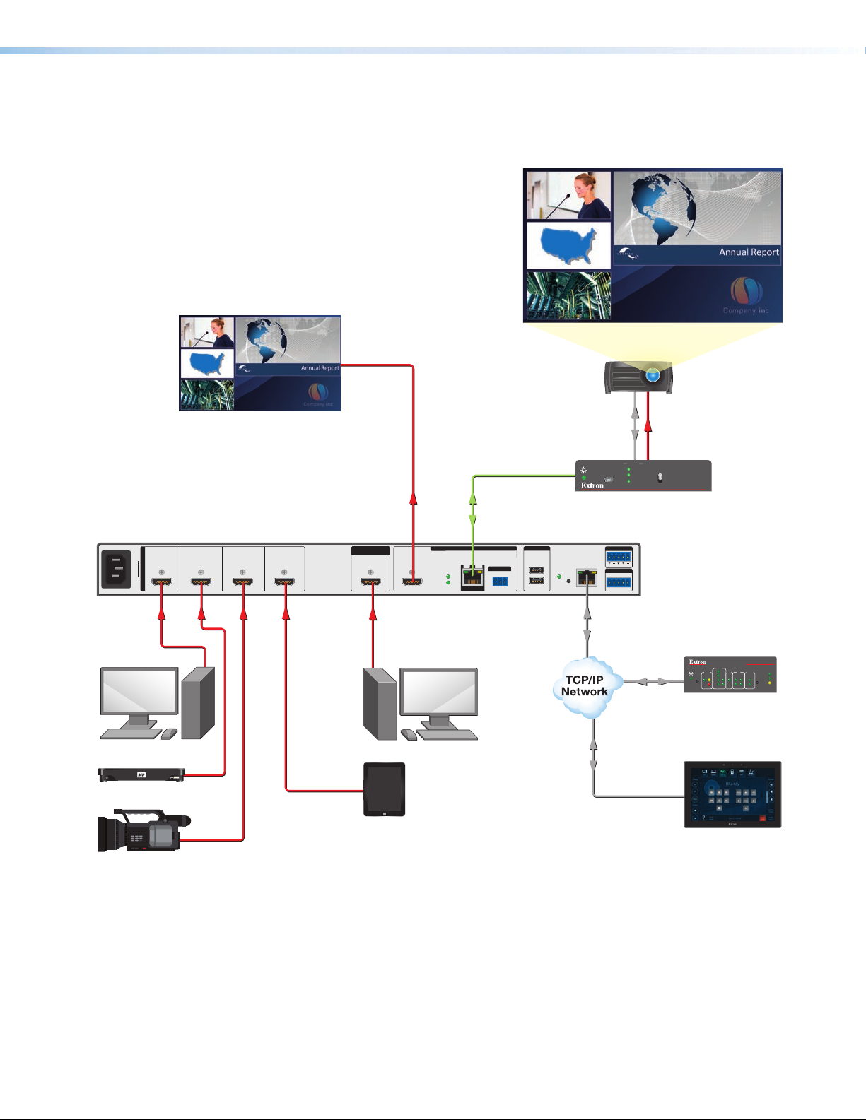
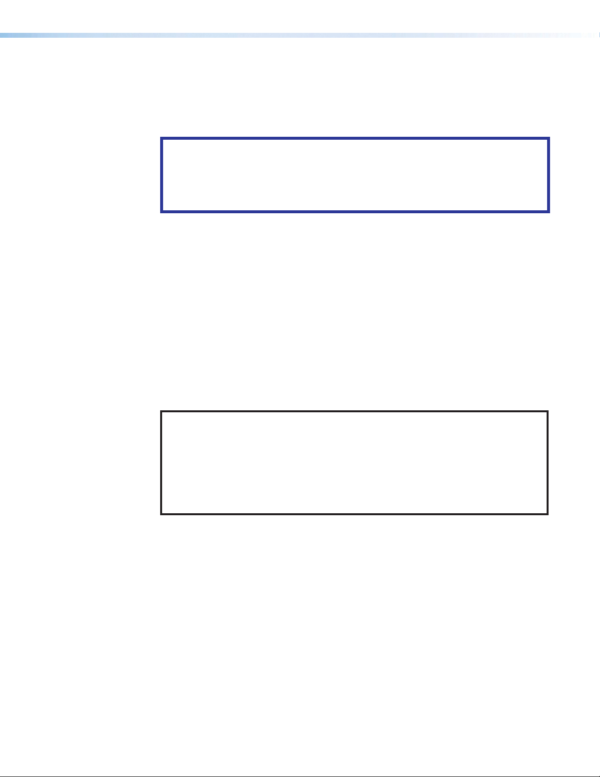
The following application diagram (see figure1) shows an example of how devices can be
connected to the MGP 641.
HDMI
CATx Cable
up to 330' (100 m)
CONFIG
Extron
DTP2 R 211
Receiver
4K Projector
HDMIRS-232
STATUS
SEND
INPUT
POWER
LINK
OUTPUT
OFF
DTP2 R 211
100-240V~--AMAX
12 4 1A3
INPUTS
MGP641
50– 60 Hz
HDMI HDMI HDMI HDMI HDMI HDMI
HDMI HDMI HDMI HDMI HDMI
PC Workstation
BACKGROUND
INPUT
OUTPUTS (DTP2/XTP/HDBT)
DTP
SIG LINK
POWER
DTP2
DTP
OUT
4K Workstation
OVER TP
Tx
USB
1
IR
Rx G
RESET
2
1B
AUDIO OUT
Extron
MGP 641
R
L
LAN
REMOTE
4K/60 HDMI Multi-Window
RS-232
Processor with DTP2 Extensio
Tx Rx G
Ethernet
IPCP PRO 250
COM
RTS
IR/S
RELAYS
eBUS
I/O
1000
1
IR
LINK
ACT
2241321
Ethernet
CTS
S
LIMIT
R
Tx
Rx
OVER
Extron
IPCP Pro 250
IP Link Pro
Control Processor
Ethernet
4K Media Player
BYOD
HDMI Camera
Extron
TLP Pro 1025T
10" Tabletop
TouchLink Pro
Figure 1. Connection Diagram for an MGP 641
MGP 641 Series • Introduction 5
Page 14

Installation
This section describes the installation procedures for the MGP 641 Multi-Graphic Processor
and the connectors on the rear panel. Topics include:
• Installation Overview
• Rear Panel Features and Connections
• Installing the LockIt HDMI Cable Lacing Brackets
• Twisted Pair Recommendations for DTP, XTP, and HDBT Communication
• RS-232 and IR Signal Insertion
Installation Overview
The MGP Processor can be connected to up to four input devices simultaneously, and up to
two output devices. Follow these steps to install the MGP 641:
1. Mount the MGP to a rack using the pre-installed side mounting brackets. The MGP 641
has a 1U high, full rack wide enclosure.
Alternatively, attach the four provided rubber feet to the bottom of the MGP and place
the unit in the desired location.
2. Connect HDMI or DVI (with an appropriate adapter) sources to the HDMI input
connectors (inputs 1 through 4), (see figure2, B on the next page).
3. If desired, connect a source to the HDMI live background connector (C). The MGP 641
windows are displayed in front of this unscaled background video source.
NOTE: You must set the output resolution to match that of the background source,
or the background video is not displayed. The refresh rates do not need to match.
4. Make the following output connections as needed:
• Connect an HDMI, or DVI with an appropriate adapter, display to the HDMI output
1A connector (D).
• Connect a DTP endpoint, XTP matrix switcher, or HDBaseT compatible receiver
to the buffered DTP/XTP/HDBT output connector 1B (F). For cable wiring and
recommendations, see Twisted Pair Recommendations for DTP, XTP, and
HDBT Communication on page11.
• To pass infrared data, connect a control device to the 3-pole Over TP IR captive
screw connector (see Over TP IR pass-through connector on page8).
5. Connect a balanced or unbalanced analog audio output device (such as a DSP device
or an amplifier) to the 5-pole captive screw Audio Out connector (K) for 2-Ch audio
from the selected input. This connector is configurable via VCS (see the VCS Help File)
or SIS (see Audio Output Format commands on page58) as two discrete mono
outputs or as one stereo output.
MGP 641 Series • Installation 6
Page 15
6. If the MGP 641 is to be connected to a computer or to a host controller for remote
control, connect an RS-232 cable from the host to the 5-pole Remote RS-232 rear
panel connector (see figure2, L) or to the front panel USB mini-B Config port (see
figure8, A, on page 3). The default protocol for the RS-232 port is 9600 baud, 1 stop
bit, no parity, and 8 data bits, with no flow control.
Alternatively, connect an RJ-45 network cable to the rear panel LAN port for remote
configuration and control.
7. Connect power to the MGP by plugging a standard IEC power cord (provided) from a
100 to 240 VAC, 50-60 Hz power source into the power receptacle (see figure2, A).
8. Apply power to all other devices.
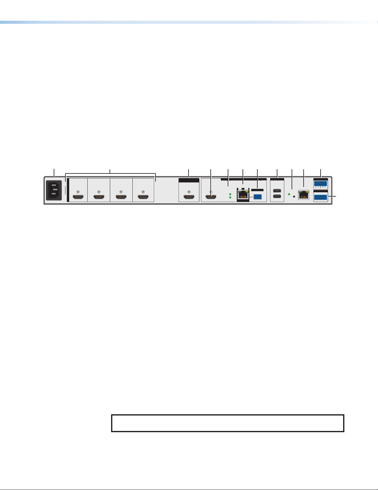
Rear Panel Features and Connections
The rear panel of the MGP 641 has the following connectors:
AAA
100-240V~ 1.5A MAX
50 – 60 Hz
BBB
12 4 1A3
INPUTS
MGP 641
HDMI HDMI HDMI HDMI HDMI HDMI
AC power connector
A
HDMI inputs
B
HDMI live background input
C
HDMI output (output 1A)
D
DTP remote power LEDs
E
DTP/XTP/HDBT output (output 1B)
F
CCC
BACKGROUND
INPUT
DDD
FFF
1B
SIGLINK
OUT
GGG
OVER TP
Rx G
Tx
III
HHH
Devices
USB 3.0
1
IR
RESET
2
900mA
EEE
OUTPUTS (DTP2/XTP/HDBT)
DTP
POWER
DTP2
DTP
Over TP IR pass-through connector
G
USB peripheral device connectors
H
Reset button and LED
I
LAN connector
J
Analog audio output connector
K
Remote RS-232 connector
L
JJJ
LAN
KKK
AUDIO OUT
L
REMOTE
RS-232
Tx Rx G
R
LLL
Figure 2. Rear Panel
AC power connector — Connect the included power cord from this male IEC
A
connector to a 100–250 VAC, 50-60 Hz power source.
HDMI inputs (inputs 1 through 4) — Connect HDMI (or DVI with an appropriate
B
adapter) sources to these four HDMI connectors, which feed directly to the windows
with the same numbers. These windows support pixel clocks up to 600 MHz and raster
sizes up to 4096 x 2400.
HDMI background input — Connect an HDMI or DVI (with an appropriate adapter)
C
input source to this HDMI connector in order to display the video source live as a
background on the output screen. The background HDMI source is displayed behind
the four MGP 641 windows and any auxiliary content. This input is not scaled.
HDMI output (output 1A) — Plug an HDMI (or DVI with an appropriate adapter) output
D
device into this HDMI connector. The HDMI output port supports resolutions up to
4K @ 60 Hz.
DTP remote power LEDs — These green LEDs light to indicate when either DTP2 or
E
DTP remote power is being provided to a receiver via the DTP output.
NOTE: Remote power is not available when the DTP Out port is set to XTP or
HDBT.
MGP 641 Series • Installation 7
Page 16
DTP/XTP/HDBT output (output 1B) — This connector and the HDMI output
IR Device
MGP 641
Tx, Rx, and G Pins
F
connector (1A) are mirrored, meaning that they display the same image (see figure2,
, on the previous page).
F
• Connect a DTP or DTP2 receiver, an XTP matrix switcher, or an HDBaseT
compatible receiver to this RJ-45 twisted pair Out connector. For cable wiring and
recommendations, see Twisted Pair Recommendations for DTP, XTP, and
HDBT Communication on page11.
• This output also allows for remote powering of DTP and DTP2 receivers, as well as
over-DTP analog audio which matches the 5-pole analog audio output of the MGP.
(It does not support remote power to XTP or HDBT devices.)
• To transmit or receive infrared data to and from a sink connected to the
DTP/DTP2/HDBT receiver or XTP matrix, connect a control device to the 3-pole
IR Over TP captive screw output port (see G, Over TP IR pass-through
connector, below).
ATTENTION:
• Do not connect this connector to a computer or telecommunications network.
• Ne connectez pas ce port à des données informatiques ou à un réseau de
télécommunications.
• DTP remote power is intended for indoor use only. No part of the network that
uses DTP remote power should be routed outdoors.
• L’alimentation DTP2 à distance est exclusivement réservée à un usage en
intérieur. Un réseau utilisant une alimentation à distance ne peut pas être routé
en extérieur.
Signal Support
DTP Mode XTP Matrix and HDBaseT Mode
• HDCP-compliant digital video
• Embedded audio into the TMDS output
or analog audio
• IR pass-through signals on the
associated Over TP 3-pole captive
screw connector
• Ethernet insertion of RS-232 control
signals (see RS-232 and IR Signal
Insertion on page11)
• HDCP-compliant digital video
• Embedded audio into the TMDS
output
• IR pass-through signals on the
associated Over TP 3-pole captive
screw connector
• Ethernet insertion of RS-232 control
signals (see RS-232 and IR Signal
Insertion on page11)
• Remote power to a DTP receiver
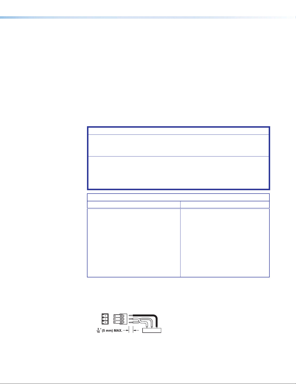
Over TP IR pass-through connector — To transmit or receive infrared data to and
G
from a sink connected to a DTP or DTP2 receiver, XTP matrix, or HDBaseT display,
connect a control device to the 3-pole Over TP IR captive screw port (see figure2, G
on the previous page). Figure 3 shows how to wire the connector.
G
IR
RxTx
G
RxTx
Figure 3. Wiring the Over TP IR Connector
MGP 641 Series • Installation 8
Page 17
NOTE: RS-232 communication can also be sent to the far end of the twisted pair
12345678
RJ-45
Connector
Insert Twisted
Pair Wires
Pins:
LAN
RJ-45
LED
connection, but it must be done through RS-232 insertion via Ethernet. A control
signal applied to an MGP 641 LAN port can be routed to the RS-232 port of
any connected twisted pair device (see Connecting for Ethernet to RS-232
Insertion on page12).
USB peripheral device connectors — (Reserved for future use)
H
Reset button and LED — Pressing the recessed Reset button causes various
I
settings to be reset to the factory defaults (see Resetting on page36 for more
information).
The green Reset LED, located to the upper-left of the reset button, blinks a varying
number of times to indicate which reset mode has been entered.
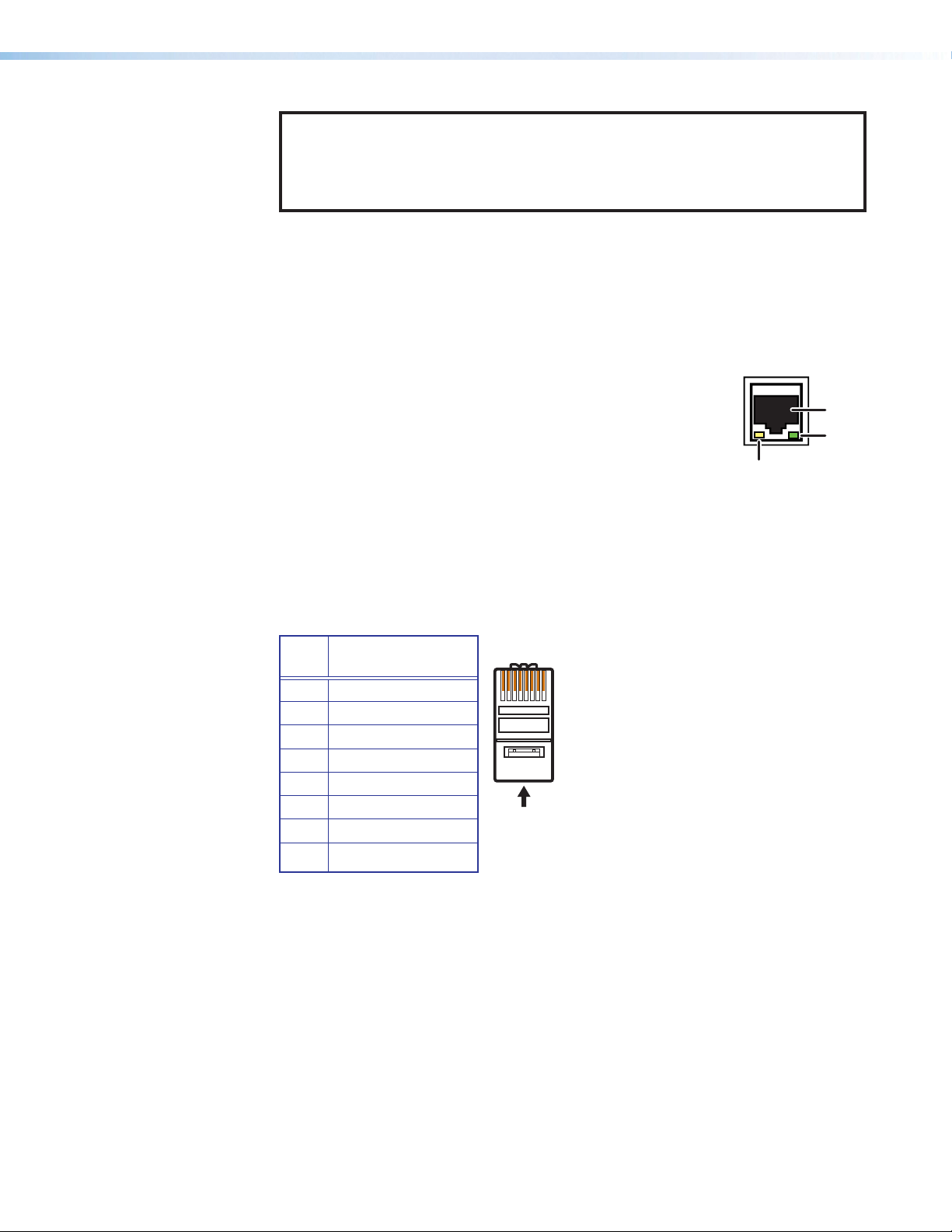
LAN connector — Plug an RJ-45 network cable into this
J
connector to connect the unit to a network (via a switch, hub, or
router) or to a single computer.
• Activity LED — This yellow LED blinks to indicate network
activity.
• Link LED — This green LED lights to indicate a good network
Activity
connection.
Use a straight-through cable to connect to a network, or a crossover cable to connect
directly to a computer.
• For 10BaseT (10 Mbps) networks, use a CAT 3 or better cable.
• For 100BaseT (maximum 155 Mbps) networks, use a CAT 5 cable.
See figure4 for LAN port wiring information.
Port
Link
LED
Pin TIA/EIA T568B
Wire Color
1 White-orange
2 Orange
3 White-green
4 Blue
5 White-blue
6 Green
7 White-brown
8 Brown
Figure 4. Wiring the LAN Connector
If desired, configure the LAN port by using SIS commands (see the LAN port setup
commands, beginning with Set IP address on page69) or by using the Comm
Settings menu on the front panel (see Comm Settings Menu on page34). The LAN
port default settings are:
IP address: 192.168.254.254
Gateway IP address: 0.0.0.0
Subnet mask: 255.255.255.0
DHCP: off
MGP 641 Series • Installation 9
Page 18
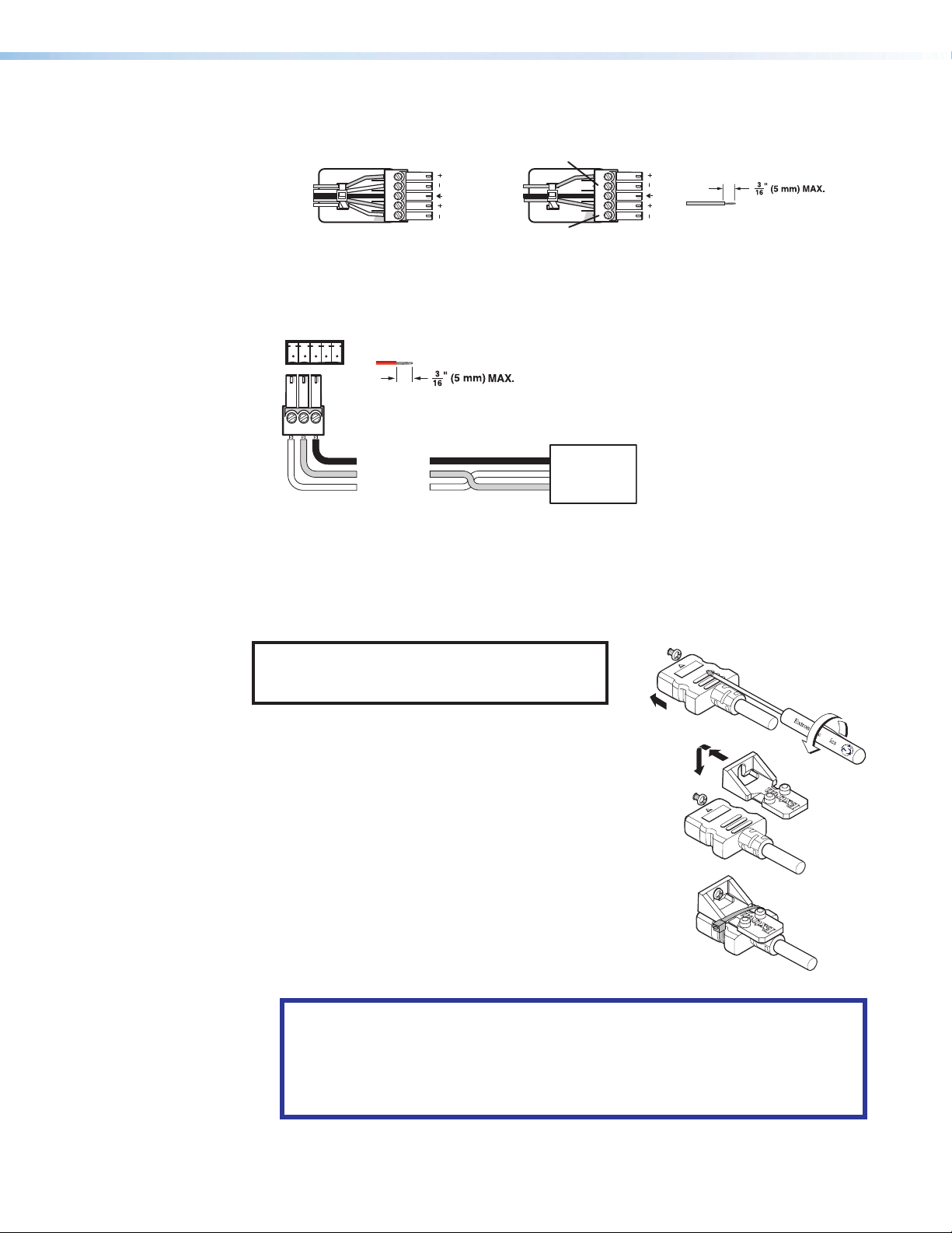
Analog audio output connector — Connect audio output devices to this 5-pole captive
!
Balanced Audio Output
Sleeves
Unbalanced Audio Output
RS-232
K
screw connector. Wire the connector for line level, balanced or unbalanced, analog stereo.
Tip
Ring
Tip
Ring
LR
No Ground Here
Tip
Sleeves
Tip
No Ground Here
LR
Do not tin the wires
Figure 5. Audio Output Connector Wiring
Remote RS-232 connector — Plug a computer or other RS-232 host device into the
L
three left-most pins (Tx, Rx, and G) of this 5-pole captive screw connector.
Tx Rx G
Do not tin the wires!
Controlling
Device
Ground (G)
Receive (Rx)
Transmit (Tx)
Bidirectional
Ground (G)
Receive (Rx)
Transmit (Tx)
Figure 6. RS-232 Connection
Installing the LockIt HDMI Cable Lacing Brackets
The Extron LockIt lacing brackets make it possible to simply and universally secure a
standard HDMI cable to most HDMI devices.
NOTE: The HDMI device must have an HDMI
connection mounting screw for this bracket to
be used.
To securely fasten an HDMI cable to a device:
1. Plug the HDMI cable into the panel connection.
2. Loosen the HDMI connection mounting screw from the
panel enough to allow the LockIt lacing bracket to be
placed over it. The screw does not have to be removed.
3. Place the LockIt lacing bracket on the screw and against
the HDMI connector, then tighten the screw to secure the
bracket.
4. Loosely place the included tie wrap around the HDMI
connector and the LockIt lacing bracket as shown.
5. While holding the connector securely against the lacing
bracket, tighten the tie wrap, then remove any excess
length.
ATTENTION:
• Do not overtighten the HDMI connection mounting screw. The shield to which
it is fastened is very thin and can easily be stripped.
• Ne serrez pas trop la vis de montage du connecteur HDMI. Le blindage auquel
elle est attachée est très fin et peut facilement être dénudé.
1
3
4
2
3
MGP 641 Series • Installation 10
Page 19
Twisted Pair Recommendations for DTP, XTP, and HDBT Communication
The MGP 641 is compatible with shielded twisted pair (F/UTP, SF/UTP, and S/FTP) cable
DTP, XTP, or HDBaseT communication.
ATTENTION:
• Do not use Extron UTP23SF-4 Enhanced Skew-Free AV UTP cable or STP201
cable to link the device with DTP transmitters or receivers.
• N’utilisez pas le câble AV Skew-FreeUTP version améliorée UTP23SF d’Extron ou
le câble STP201 pour relier le appareil avec les émetteurs ou les récepteurs DTP.
Extron recommends using the following practices to achieve full transmission distances and
reduce transmission errors.
• Use the following Extron XTP DTP 24 SF/UTP cables and connectors for the best
performance:
• XTP DTP 24/1000 Non-Plenum 1000' (305 m) spool
• XTP DTP 24P/1000 Plenum 1000' (305 m) spool
• XTP DTP 24 Plug Package of 10
• If not using XTP DTP 24 cable, at a minimum, Extron recommends 24 AWG, solid
conductor, STP cable with a minimum bandwidth of 400 MHz.
• Terminate cables with shielded connectors to the TIA/EIA-T568B standard.
• Limit the use of more than two pass-through points, which may include patch points,
punch down connectors, couplers, and power injectors. If these pass-through points
are required, use shielded couplers and punch down connectors.
NOTE: When using shielded twisted pair cable in bundles or conduits, consider the
following:
• Do not exceed 40% fill capacity in conduits.
• Do not comb the cable for the first 20 meters, where cables are straightened,
aligned, and secured in tight bundles.
• Loosely place cables and limit the use of tie wraps or hook-and-loop fasteners.
• Separate twisted pair cables from AC power cables.
RS-232 and IR Signal Insertion
The twisted pair output port allows you to insert RS-232 and IR control signals onto the
same cable that carries video and audio to extend them to the Over TP port on a connected
endpoint (see figure7 on page12).
A control signal applied to an MGP 641 LAN port can be routed to the RS-232 port of the
connected twisted pair device. The RS-232 inputs and outputs inserted via Ethernet can
support up to a 115 K baud rate.
When connected to an Ethernet LAN, the MGP can be accessed from a computer running
a standard Internet browser. Connect the MGP to a computer, control device, router, or
switch (see figure4 on page9 to wire the crossover cable).
The default IP address of the MGP 641 is 192.168.254.254, the default subnet mask is
255.255.255.0, and the default gateway address is 0.0.0.0.
MGP 641 Series • Installation 11
Page 20
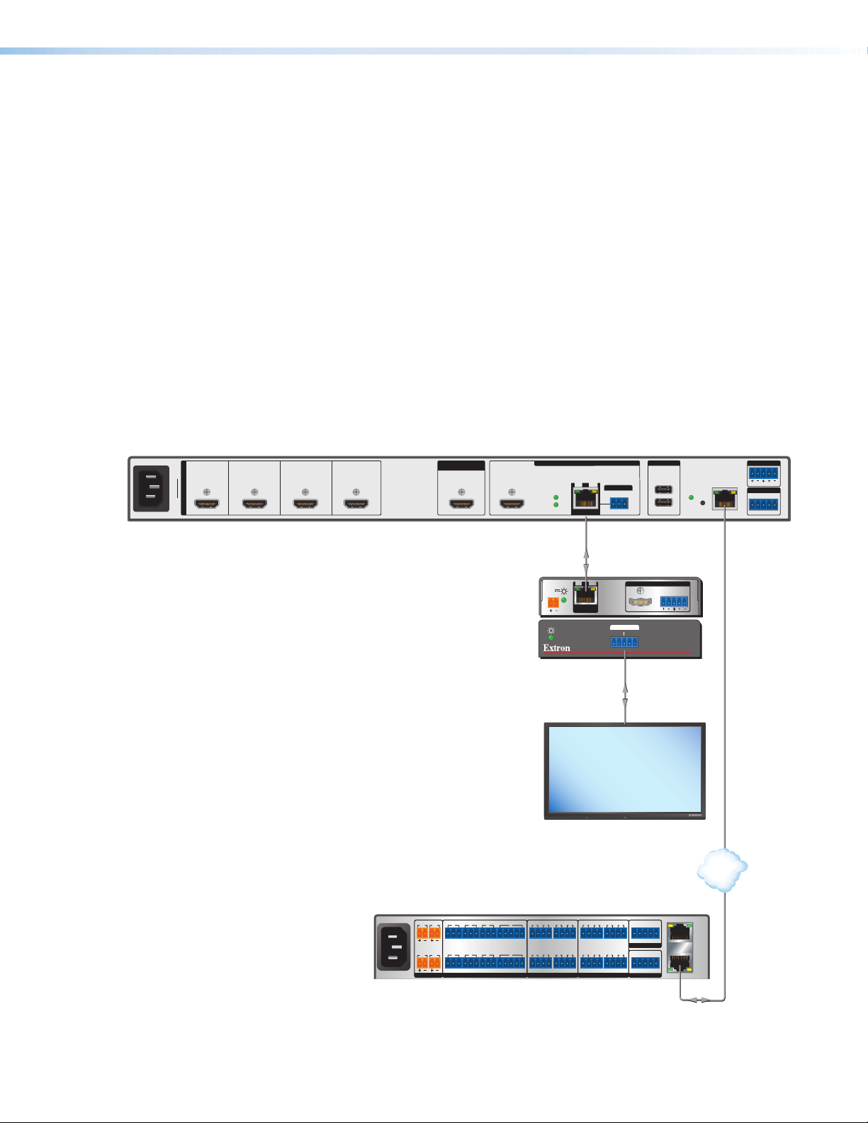
Connecting for Ethernet to RS-232 Insertion
RS-232 Insertion
Figure7 on the next page shows a connection example of an Ethernet to RS-232 insertion,
in which an Extron IPCP Pro control processor provides control of a display via the
MGP 641. Configure this type of insertion as follows:
1. Connect a twisted pair cable from the control processor to the MGP 641 LAN port,
directly or via a network.
2. If necessary to match the device to be controlled, use VCS (see the VCS Help File)
or SIS commands (see the Serial Port Configuration commands on page 67) to
configure the port RS-232 protocol (baud rate, parity, data bits, and stop bits).
3. Connect the TP cable from the MGP 641 DTP Out connector to the input of the DTP
endpoint (receiver).
4. Connect a serial cable from the DTP receiver to the device to be controlled.
Port number
For Ethernet to RS-232 insertion, the insertion port number must be stated from a specific
universal asynchronous receiver-transmitter (UART) start point. This number is entered as
the IP port number when you establish communication with the insertion port. The output
insertion port number is automatically assigned as 2001 and cannot be changed.
100-240V~ 1.5AMAX
50 – 60 Hz
MGP 641
12 4 1A3
INPUTS
MGP641
HDMI HDMI HDMI HDMI HDMI HDMI
BACKGROUND
INPUT
OUTPUTS (DTP2/XTP/HDBT)
DTP
POWER
DTP2
DTP
OUTPUTS
SIGLINK
OUTPUTS
Devices
1B
OVER TP
Tx
OUT
USB 3.0
1
IR
Rx G
RESET
2
900mA
AUDIO OUT
R
L
LAN
REMOTE
RS-232
Tx Rx G
RS-232
SIG LINK
POWER
12V
0.7A MAX
DTP IN
DTP HDMI 330 Rx
OVER DTP
RS-232
TxRx Tx RxG
Rear Panel
OUTPUTS
IR
DTP HDMI 330 Rx
Front Panel
AUDIO
LR
RS-232
MODEL 80
FLAT PANEL
Display
AV LAN
100-240V ~ 50-60Hz
1.2A MAX
1 2
SWITCHED 12 VDC
40W MAX TOTAL
3 4
12 VDC
142 3 7
TxRx GTxRxGTx Rx GTxRxG
5 6 8
COM
CTS
SGSG SGSG
RTS
5 6 7 8 5 6 7 8
SGSG SGSGTxRx GTxRxGTx Rx GTxRxG
RTSCTS
1 2 3 41 2 3 4
PWR OUT = 12W
+V +S -S G
eBUS
3214G
FLEX I/ORELAYSIR/SERIAL
LAN
AV
LAN
Control Processor
Figure 7. Typical Ethernet to RS-232 Insertion to an Endpoint
MGP 641 Series • Installation 12
Page 21
Operation
This section describes setup and operating procedures for the MGP 641 available from the
front panel. The following topics are discussed:
• Front Panel Features
• Power-up and Default Cycle
• Selecting a Window and Input
• Muting and Freezing a Window
• Presets
• Menus, Configuration, and Adjustments
• Additional Functions
You can set up and operate the MGP 641 using:
• The front panel controls
• A computer, a touch screen panel, or any other device that can send and receive
communications through the USB port, the Remote RS-232 port, or the LAN port.
Settings can be adjusted through the host computer using SIS commands or VCS.
• A computer or other device using an Ethernet connection and IP protocol (Telnet or a
web browser).
For details on setup and control, see Remote Configuration and Control starting on
page38
page79
. For web page control, see the HTML Configuration and Control starting on
. For configuration and control via VCS, see the VCS Help File.
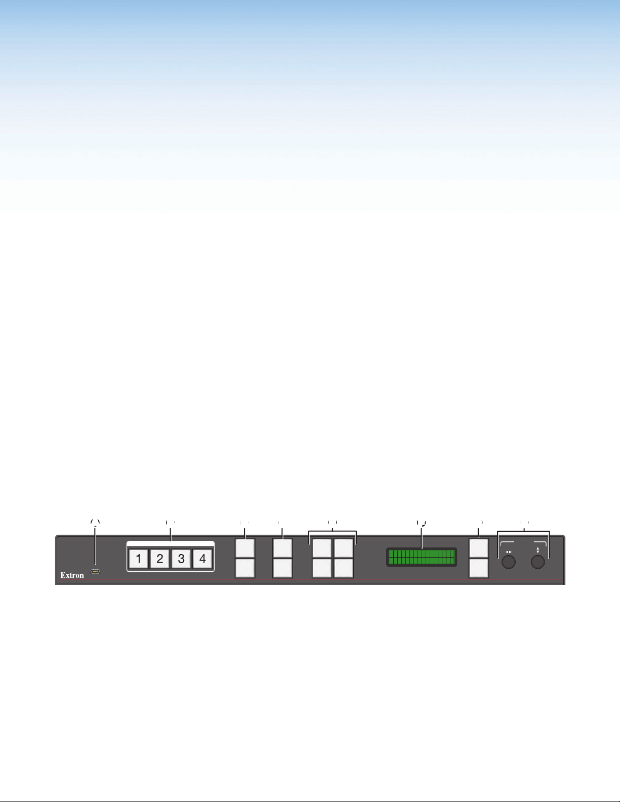
Front Panel Features
AA
CONFIG
BB
WINDOW SELECT
USB Config port
A
Window and input selection buttons
B
Mute and Freeze buttons
C
Preset Recall/Save and Enter buttons
D
Figure 8. MGP 641 Front Panel
USB Config port — Connect a host device to this USB mini-B port for device
A
configuration, control, file transfer, and firmware upgrades.
Window and input selection buttons — Press one of these buttons to select
B
windows 1 through 4 for configuration. The selected button lights orange.
CC
MUTE
FREEZE
DD
PRESET
RECALL
/SAVE
ENTER
WINDOW
/IMAGE
SIZE
WINDOW
/IMAGE
POSITION
EE
WINDOW
/IMAGE
ZOOM
AUTO
IMAGE
FF
Picture control buttons
E
LCD screen
F
Menu navigation buttons
G
Adjust knobs
H
MGP 641 Series • Operation 13
GG
MENU
NEXT
HH
ADJUST
MGP 641
MULTI-GRAPHIC PROCESSOR
Page 22

Mute and Freeze buttons —
C
• Mute — Press this button to mute the selected window. The button lights orange
when the mute is enabled. To unmute, press the lit Mute button again.
• Freeze — Press this button to freeze the selected window. The button lights
orange when freeze is enabled. To unfreeze the window, press the lit Freeze
button again.
Preset Recall/Save and Enter buttons — In combination, these buttons save the
D
current settings to a window preset or recall a stored preset (up to 128). Press Preset
Recall/Save, then rotate the Adjust knobs to select a window preset to recall. Press
Enter to complete the action.
Press and hold Preset Recall/Save to save a window preset.
Picture control buttons — Press these buttons to adjust the size, position, and zoom,
E
or to perform an auto-image adjustment on the selected window.
• Press Window/Image Size, Window/Image Position, or Window/Image Zoom
once to select the window (the button lights orange) or twice to select the image
within the window (the button lights green).
Use the horizontal ([) and vertical ({) Adjust knobs to adjust the settings shown
on the left and right sides of the LCD screen, respectively.
• Press Auto-Image to perform an Auto Image adjustment on the selected input
window. Press it again to confirm the adjustment.
LCD screen — Displays the configuration menus, messages, and your selections.
F
Menu navigation buttons — Press Menu to step through the menus on the LCD
G
screen. From each menu, press Next to step through its submenus.
Adjust knobs — Turn the horizontal ([) and vertical ({) Adjust knobs to scroll
H
through submenu options and preset memory slots, and to adjust picture
Power-up and Default Cycle
When the MGP 641 first powers up, the LCD screen displays an initial sequence of three
screens:
1. Extron
2. MGP 641
3. 60-1574-01 (product part number)
FW n.nn.nnnn (firmware version)
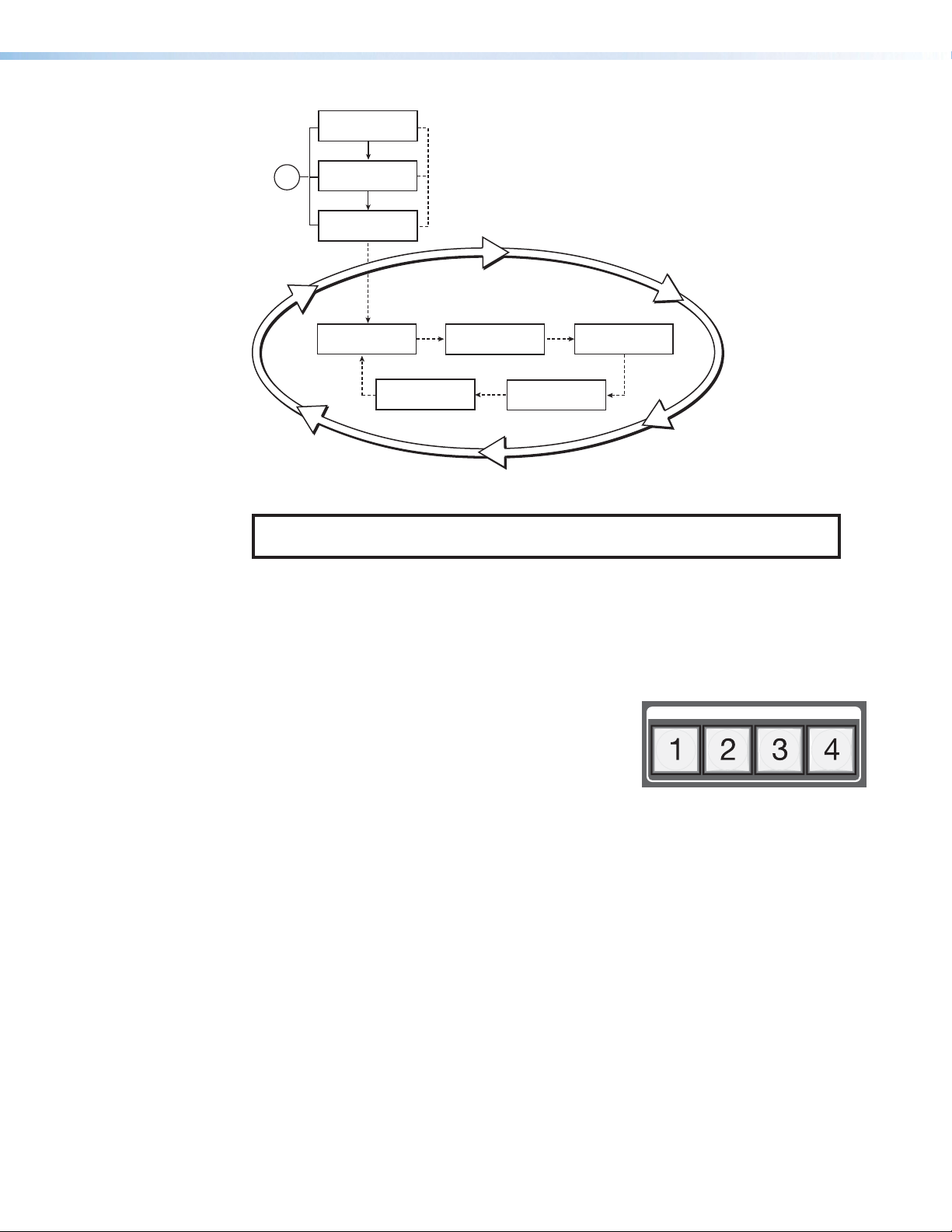
The initial sequence is followed by the default cycle of screens showing the current input
type for each window and the output resolution and refresh rate. These messages continue
to cycle on the LCD screen when the menu system is not in use. Figure9 on the next page
shows a flow diagram of the order in which these screens are repeated.
MGP 641 Series • Operation 14
Page 23
Extron
Power
on
Extron
MGP 641
60-1574-01
FW n.nn.nnnn
2 sec.
Win 1 Signal Type
Resolution@Rate
2 sec.
Resolution@Rate
Figure 9. Default Cycle Example
NOTE: From any menu or submenu, the MGP 641 saves all adjustment settings
and times out to the default screens after 30 seconds of inactivity.
Selecting a Window and Input
Default Cycle
2 sec.
Output Rate
Win 2 Signal Type
Resolution@Rate
Win 4 Signal Type
2 sec.
Resolution@Rate
Win 3 Signal Type
2 sec.
Resolution@Rate
2 sec.
The MGP 641 has four windows in which to display sources. To select a window is to select
its associated input, or logo if assigned
Window Select Buttons
The four Window Select buttons let you select which
WINDOW SELECT
window is affected by the Mute, Freeze, and Picture
Control buttons, as well as the menu selections on the
LCD screen.
When you select a picture control, the window whose button was previously selected is
affected (see Picture Controls on page19 for information on the available controls.)
To select a window, press its Window Select button, which lights. To deselect a window,
press any other Window Select button. Only one window can be selected at a time.
MGP 641 Series • Operation 15
Page 24
Muting and Freezing a Window
Mute
The Mute button is located to the right of the Window Select buttons on the
front panel (see figure8 on page13). To mute a window (remove the window
from being displayed on the output):
1. Select the desired Window Select button.
2. Press Mute. The button lights orange and remains lit while the input is
muted.
To unmute the window, press Mute again.
When a window is muted or unmuted, the currently selected transition effect (cut or
fade), if any, is employed as the window on the display closes or opens (see Window
Configuration Menu on page27 for information on transition effects).
You can also mute and unmute the windows using VCS (see the VCS Help File) or SIS
commands (see the Window Mute commands on page 50).
If the unit loses power, the mute status is maintained and the output of the MGP appears as
it did when power was lost.
If a window is muted and the source to that window is changed or removed, the window
remains muted until manually frozen.
MUTE
FREEZE
Freeze
The front panel Freeze button is located below the Mute button (see figure8). Press
Freeze to freeze the image in the selected window. When the window is frozen, this button
lights orange and remains lit while Freeze is enabled. To unfreeze the image, press Freeze
again. The button LED turns off.
You can also freeze the windows using VCS (see the VCS Help File) or SIS commands (see
the Freeze commands on page 51).
If the unit loses power, the freeze function is disabled when power is restored. If an image is
frozen and the source to that window is changed or removed, the image remains frozen until
manually unfrozen.
Presets
Window Presets
A preset is a set of window (input) parameters that you create and save as a preset
in MGP 641 memory. You can recall a saved preset and implement its settings at any
time. A preset enables you to save time by applying a group of settings to the MGP 641
simultaneously.
The MGP 641 provides 128 slots for window presets that save information
for all the windows. Use the Preset Save/Recall and Enter buttons on the
front panel to save and recall presets. Window presets can also be saved,
recalled, and named using VCS (see the VCS Help File) or SIS commands via
RS-232 (SIS only), USB, or Ethernet connection (see the Presets commands
starting on page56).
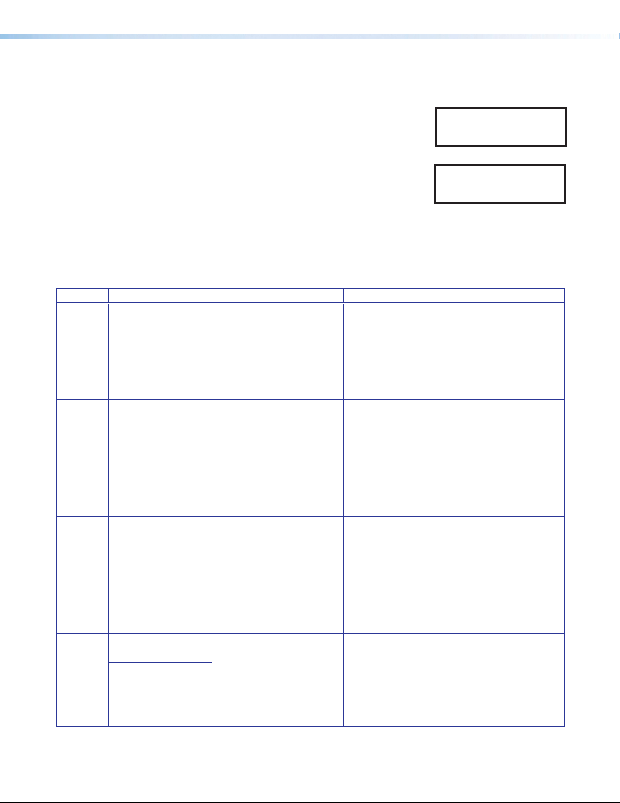
The table on the next page shows the settings that are saved in a window
preset.
MGP 641 Series • Operation 16
PRESET
RECALL
/SAVE
ENTER
Page 25
Window Settings Global Settings
• Window size and position
• Image size and position in the window
• Window mute status
• Active window border style
• Window priority
• Window source (HDMI or logo preset)
• Background source
• Background logo preset number (if used)
• Foreground logo preset number (if used)
• User defined color (if used)
Saving a window preset
To save a window preset using the front panel buttons:
1. Press and hold the Preset Recall/Save button until
the message shown at right appears (approximately
2 seconds). The Preset Recall/Save button lights
green.
2. Rotate either Adjust knob to select one of the 128 available window preset slots.
3. Press the Enter button, located below the Preset
Recall/Save button, to save the current window
settings in the selected preset location.
The LCD screen shows a message indicating that
the preset is being saved to the selected memory
location, followed by a message that the preset has
been saved (see the images at right).
If you want to exit the preset dialog without saving any changes, press the Menu button
or wait until the Preset Recall/Save button turns off (about 30 seconds).
Window Preset
Save To #001
Window Preset
Save #nnn
Window Preset
#nnn Saved
Recalling a window preset
To recall a window preset using the front panel buttons:
1. Press and release the Preset Recall/Save button.
The button lights orange and the LCD screen displays
the message shown at right.
2. Use either Adjust knob to select a window preset number to recall.
3. Press the Enter button to recall the selected preset
selected. The LCD screen shows a message indicating
that the preset was recalled (see the image at right).
Recalled presets apply to both outputs.
Window Preset
Recall #nnn
Window Preset
#nnn Recalled
MGP 641 Series • Operation 17
Page 26
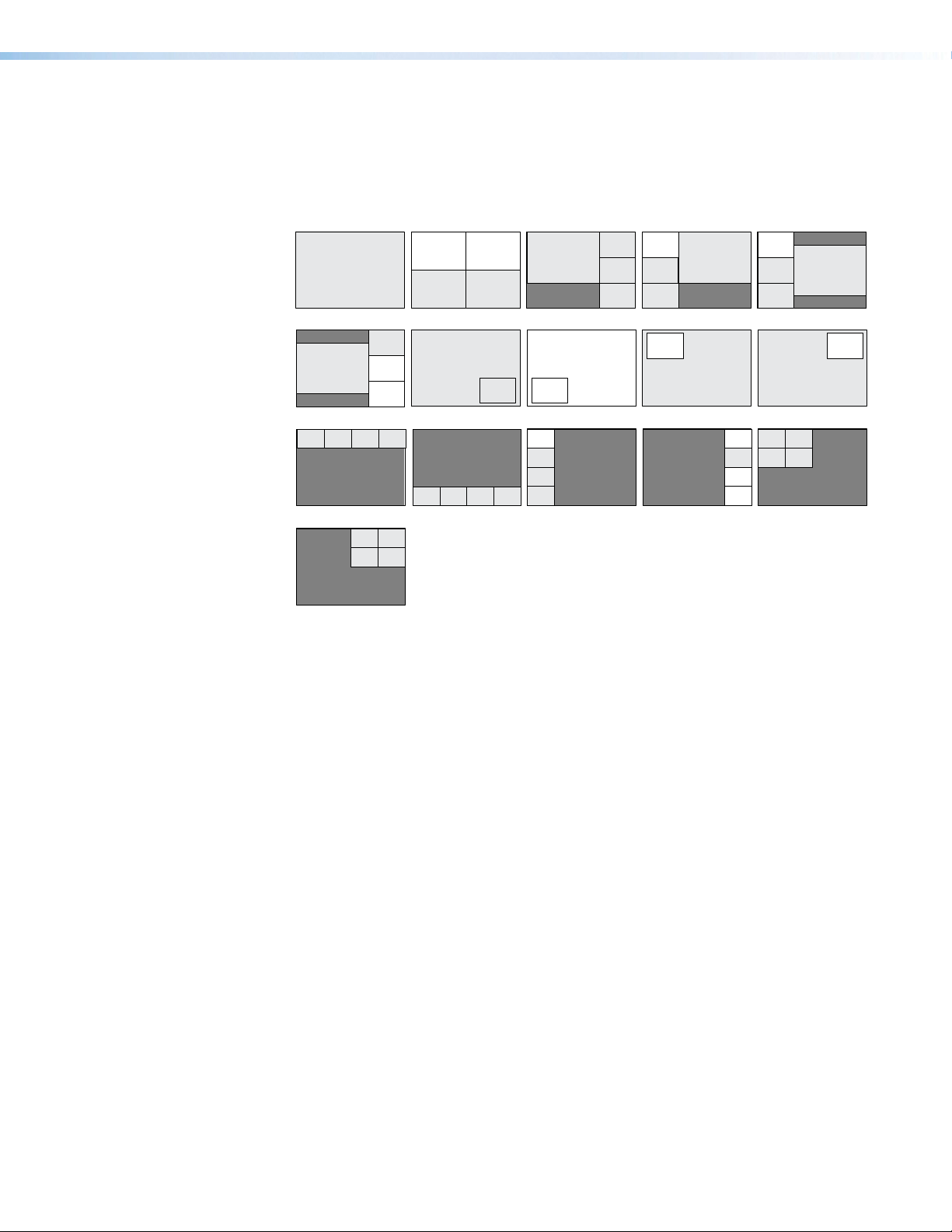
Default window presets
Preset #1 Preset #2 Preset #3 Preset #4 Preset #5
Pr
Figure 10 shows the 16 different factory default preset window configurations for the
MGP 641. These presets can be used for any output rate, and do not have border
styles associated with them (see the Presets commands on page56). By default, the
16 presets are repeated to fill all 128 preset locations.
2
1,2,3,4
Fullscreen
3 4
21
1
2
3
3
4
4
1
2
3
4
1
Preset #6
1
Preset #7 Preset #8 Preset #9 Preset #10
2
3
4
1
2
eset #11Preset #12
2 31 4
2 31 4
Preset #16
2
314
Figure 10. Factory Default Preset Configurations
Input Presets
The MGP 641 has 128 input preset slots that are global, containing all of the settings for
an input when the MGP 641 is used with an upstream matrix switcher. Input presets allow
a matrix switcher with multiple types of video inputs to be connected to the MGP 641 to
expand the number of input video sources.
Each input should be switched into the MGP 641, configured (size, position, and preset
name), then saved as a preset for recall by the control system when that input is sent from
the switcher to any of the four MGP inputs.
Input presets can be saved and recalled using VCS (see the VCS Help File) or by SIS
commands (see the Input Presets commands on page57).
The following settings are contained in the input presets:
• Input type
• Input name
• Image position
• Image size
• Window size (for reference)
Image size and position are saved based on the percentage of the window filled, so the
preset can be used for the input in any window size. Therefore, the preset can be saved
from any window and the saved size and position is scaled proportionally when recalled in
another window.
2
1
2
1
1
Preset #13Preset #14Preset #15
1
2
3
4
1
2
3
4
2
314
2
MGP 641 Series • Operation 18
Page 27
Picture Controls
When an input preset is recalled to a window, it fills the window based on the sizing and
positioning that the preset had at the time that it was saved. For example, if a video source
had been zoomed into when it was saved as a full screen window, it is still displayed
zoomed in if it is recalled to a smaller window.
Since all inputs are digital, input presets can be saved based on one input rate and recalled
to a different input rate. This enables presets to be used to set aspect ratio or for other
quick sizing shortcuts.
The MGP 641 has four picture control buttons located on the
front panel to the left of the Preset Recall/Save and Enter
buttons. Use these buttons to adjust horizontal and vertical size,
horizontal and vertical position, Auto Image, and magnified focus
(zoom).
NOTE: Picture controls are window-dependent. The values
must be set separately for each window.
• Pressing a Picture Control button once displays the picture control for the selected
window on the LCD screen. While the control is displayed, pressing any of the other
window buttons displays the picture control settings for that window.
• For the Window/Image Size, Window/Image Position, and Window/Image Zoom,
buttons, press the button repeatedly to switch between window settings and image
settings.
The selected window displays a blinking blue border, whether or not a border is enabled for
that window.
WINDOW
/IMAGE
SIZE
WINDOW
/IMAGE
POSITION
WINDOW
/IMAGE
ZOOM
AUTO
IMAGE
Adjusting the Picture Controls
Use the Picture Controls buttons to make adjustments to an input window or perform
an Auto-Image. When you select one of these buttons, the button for the most recently
selected window lights, indicating that the window is being adjusted.
Adjusting window and image picture controls for position, size, or
zoom
1. Press the Window Select button for the window (input) to adjust.
2. Press the button for the desired picture control: Window/Image Size (sizing),
Window/Image Position (moving and centering), Window/Image Zoom (magnification),
and Auto-Image. The controls are displayed on the LCD screen.
3. Rotate the horizontal Adjust ([) or vertical Adjust ({) knob to select a level from the
available range.
4. Repeat steps 1 through 3 for each window or image adjustment to be made for the
selected input.
MGP 641 Series • Operation 19
Page 28
Performing Auto-Image
1. Press the Window Select button for the window to
adjust.
2. Press the Auto-Image button. The button blinks green,
and the message shown at right appears on the LCD
Auto Image Win n
Press Auto = Go
screen.
3. Press Auto-Image again to initiate the Auto Image.
When the process is complete, the Auto Image button
turns off. A message appears briefly on the LCD screen
(see the image at right), then the screen returns to the
Auto Image Win n
Complete!
default cycle.
Picture Controls Summary
The following table summarizes the functions of the picture control buttons and how to
make adjustments.
Button Display Function Range Adjust Knob
Window/
Image
Size
Size: Window 1
H=960 V=540
(Press button twice.)
Size: Image 1
H=960 V=540
Enlarge or shrink window n. Min: 1/16 of output rate
Max: 2 times output
rate
Enlarge or shrink the image
of input nn within the
window.
Min: 1/16 of output rate
Max: 2 times output
rate
For H (width):
Horizontal
knob
For V (height):
Vertical
{
Adjust
knob
[
Adjust
Window/
Image
Center: Window 1
H=+0 V=+0
Position
(Press button twice.)
Center: Image 1
H=0 V=0
Position the upper-left
corner of window n on the
display in relation to the
display center.
Position the upper-left
corner of the image of
input nn within the window
Default: 0000 ± output
rate
Default: 0000 ± output
rate
For H: Horizontal [
Adjust knob
For V:
Vertical
{
Adjust
knob
in relation to the window
center.
Window/
Image
Zoom
Zoom: Window 1
H=960 V=540
(Press button twice.)
Zoom: Image 1
H=960 V=540
Increase or decrease the
size of the selected window
while keeping the aspect
ratio constant.
Increase or decrease the
size of the image of input
n in the selected window
Min: 1/16 of output rate
Max: 2 times output
rate
Min: 1/16 of output rate
Max: 2 times output
rate
For H:
Horizontal
knob
For V:
Vertical
{
knob
[
Adjust
Adjust
while keeping the aspect
ratio constant.
AutoImage
Auto Image Win 1
Press Auto = Go
(Press button again.)
When completed:
Auto Image Win 1
Complete!
Performs an Auto Image
adjustment to the currently
selected window. Size and
position are reset to defaults
for the input aspect ratio
setting.
Fill: Horizontal and vertical image position return
to 0,0, and the image size is set to match the
current window size.
Follow: Horizontal and vertical image position
and size are set to maintain the native aspect
ratio for the input rate with respect to the window
being affected.
MGP 641 Series • Operation 20
Page 29
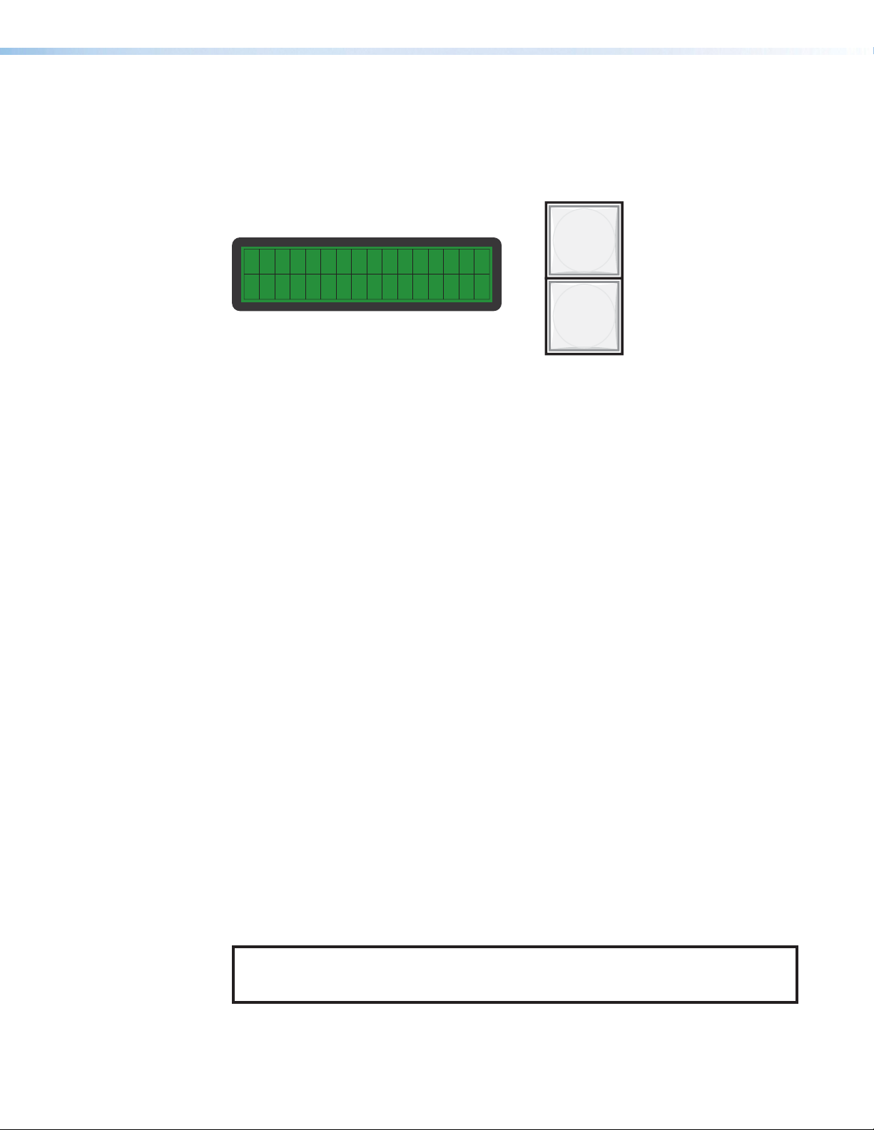
Menus, Configuration, and Adjustments
The MGP 641 menus enable you to configure the processor. The names of the menu,
submenus, and options are displayed on the LCD screen on the front panel. The menu
navigation buttons (Menu and Next) are located to the right of the LCD screen (see
figure11). Press these buttons to cycle through the available menu and submenu options.
Figure 11. LCD Screen with Menu and Next Buttons
Menu System Overview
The MGP 641 menu system consists of a main menu with seven options (menus). Each of
these seven menus has a set of submenus, which enable you to make desired adjustments
(see the Main Menu Flow diagram in figure12 on page22).
Using the menus
Access the different levels of menus by pressing the Menu and Next buttons and turning the
Adjust knobs as follows:
1. Main menu access — To access the main menu, press the Menu button. The first
main menu option (Input Configuration) is displayed on the screen.
2. Main menu options (menus) — Repeatedly pressing the Menu button cycles through
the main menu options. Press the Menu button until the desired menu is displayed.
3. Submenu options — When the desired main menu item that you want to configure
is displayed on the LCD screen, press the Next button to cycle through the submenu
options of the displayed menu.
4. Adjustments — With a desired submenu option displayed, rotate the horizontal ([)
and vertical ({) Adjust knobs clockwise or counterclockwise to display and select the
parameters available for the option.
5. Implementation — To save and implement the adjustments you have selected, do one
of the following:
• Press Next to display another submenu option to adjust.
• Press Menu repeatedly until the Exit menu screen appears, then press Next.
• Do nothing more, and wait until the LCD screen returns to the default cycle
(approximately 30 seconds).
Your adjustments remain in effect until you change them or reset the unit to factory defaults
(see Resetting on page36).
MENU
NEXT
NOTE: The menus time out and the default cycle displays after 30 seconds of inactivity.
Any selections made with the Adjust knobs prior to time-out are saved and remain in
effect.
MGP 641 Series • Operation 21
Page 30
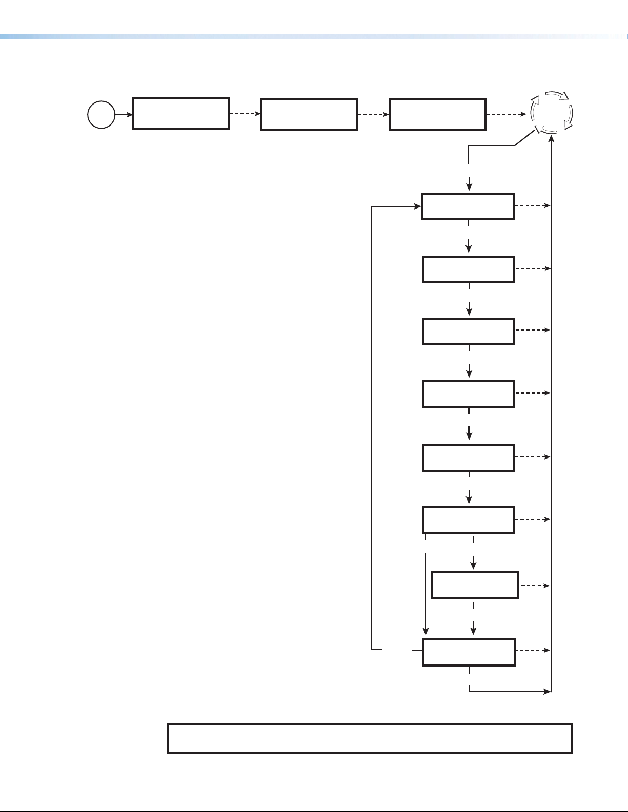
Main menu flow
Power
On
Extron
2 sec.
Extron
MGP 641
2 sec.
60-1574-01
FW n.nn.nnnn
INPUT
CONFIGURATION
OUTPUT
CONFIGURATION
WINDOW
CONFIGURATION
IMAGE/LOGO
CONFIGURATION
Menu
Menu
Menu
Menu
2 sec.
Default
Cycle
30 sec.
30 sec.
30 sec.
30 sec.
Menu
ADVANCED
CONFIGURATION
Menu
30 sec.
VIEW COMM
30 sec.
Menu
SETTINGS
Hold 3 sec.
EDIT COMM
SETTINGS
30 sec.
Menu
Menu
EXIT MENU
PRESS NEXT
30 sec.
Next
Figure 12. Main Menu Flow
NOTE: From any menu or submenu, the MGP 641 saves all adjustment settings and
times out to the default screens after 30 seconds of inactivity.
MGP 641 Series • Operation 22
Page 31

Input Configuration Menu
The Input Configuration menu allows you to configure settings for the HDMI input
associated with the selected window. The input being configured is determined by the
window number currently selected on the front panel.
Menu
Configuration
n: EDID
Match Output
Next
Select an EDID:
• Match Output
• C1:1920x1080@60 (Default)
(9 more custom EDIDS)
• 640x480@60Hz
(20 more EDIDs)
Input
Next
Rotate either Adjust knob
to select submenu options.
n: H Active V
Next
1024* *786
(View-only)
Next
n: Aspect Ratio
Fill
• Fill
• Follow
Next
n:HDCP Authorize
On
• On
• Off
Next
n: Image Rotate
Disabled
• Disabled
• +90 Degrees
• -90 Degrees
Next
Figure 13. Input Configuration Menu Flow
Input Configuration submenu options
• EDID — Rotate either Adjust knob to select an EDID for the current input from a list of
20 factory-supplied EDIDs, or select Match Output (default) to use the current output
resolution and refresh rate.
In addition, 10 custom EDID slots are provided. These EDIDs can be captured from a
connected display device or uploaded via SIS or VCS. The 10 custom, user-defined
output rates default to 1080p @ 60 Hz when no custom EDID is captured or uploaded.
(See Output Resolutions and EDID Emulation on page43 for a list of the available
EDIDs.)
• Active — This view-only screen shows the active pixels (H) and lines (V) of the detected
input signal on the currently selected window.
• Aspect Ratio — Select the aspect ratio of the image relative to the window in which it
is displayed. The options are:
• Fill — Each input signal fills its entire window (default).
• Follow — Each input signal is displayed with its native aspect ratio.
• HDCP Authorize — Select On (default) or Off. This option lets you disable HDCP
communication on discrete inputs.
For source devices that require encryption, select On to enable HDCP authorization.
This setting is useful for devices such as Mac computers, iPhones, iPads, and some
Windows sources that always encrypt their output, regardless of whether they are
displaying HDCP content, if the downstream sink is capable of HDCP. By not allowing
HDCP signals on an input, the MGP can pass most content from these sources as a
non-encrypted signal to analog and digital video outputs.
When HDCP authorization is disabled, the window displaying an encrypted source does
not display content that requires HDCP. Instead, the window displays either a black
screen or a warning message generated by the source.
MGP 641 Series • Operation 23
Page 32

NOTE: All windows must not be displaying HDCP content for the MGP output to
not be encrypted.
• Image Rotate — This option enables you to rotate the individual inputs 90 degrees
clockwise or counterclockwise, allowing for support of either portrait inputs on a
standard landscape oriented output or landscape sources on a portrait oriented output.
Image rotation is available for all MGP resolutions and rates.
NOTE: Image rotation is available only on windows 2 and 4. If the selected window
is 1 or 3, the screen shows Not Available for this option.
Rotation selections include:
• Disabled (default)
• + 90 degrees (90° clockwise)
• - 90 degrees (90° counterclockwise)
Output Configuration Menu
The Output Configuration menu allows you to set output resolution and refresh
rate, output signal type, and sync polarity. The following flow diagram shows the Output
Configuration submenus and the adjustments that can be made from them.
Input
Configuration
Menu
Next
Output
Configuration
Next
Output Rate
1080p@60Hz
Resolution Refresh Rate
See the table on the next page for
available combinations of resolutions
and refresh rates.
Default: 1920 x 1080 @ 60 Hz (1080p)
Next
1A: HDMI Format
Auto
• Auto (default)
• DVI RGB 444
• RGB 444 Full
• RGB 444 Limited
• YUV 444 Limited
• YUV 422 Limited
Next
1B: TP Format
Auto
• Auto (default)
• DVI RGB 444
• RGB 444 Full
• RGB 444 Limited
• YUV 444 Limited
• YUV 422 Limited
Next
Display Rotate
Off
• Off (default)
• +90 Degrees
• -90 Degrees
Next
HDCP Note
Green
Screen
• Green Screen (default)
• Black Screen
Figure 14. Output Configuration Menu Flow
• Output Rate — While this option is displayed, rotate the horizontal Adjust ([) knob
to select one of the available resolutions, or rotate the vertical Adjust ({) knob to select
one of the refresh rates. The resolutions and refresh rates are listed in the Refresh
Rates in Hz Table on page25.
MGP 641 Series • Operation 24
Page 33

Resolution
Refresh Rates in Hz Table
23.98 Hz 24 Hz 25 Hz 29.97 Hz 30 Hz 50 Hz 59.94 Hz
60 Hz
640 x 480 X
800 x 600 X
852 x 480 X
1024 x 768 X
1280 x 768 X
1280 x 800 X
1280 x 1024 X
1360 x 768 X
1366 x 768 X
1440 x 900 X
1400 x 1050 X
1600 x 900 X
1680 x 1050 X
1600 x 1200 X
1920 x 1200 X
480p X X
576p X
720p X X X X X X
1080i X X X
1080p X X X X X X X X*
2048 x 1080
X X X
X X X X X
2048 x 1200 X
2048 x 1536 X
2560 x 1080 X
2560 x 1440 X
2560 x 1600 X
3840 x 2160 X X
4096 x 2160** X X
X
X
X X X X X
X X X X X
Custom 1 - 10 For new resolutions
* Default
** Resolution not available as an EDID, only as an output rate option
MGP 641 Series • Operation 25
Page 34

By default, the resolution provided in the EDID is the last selected factory rate. To
manually set the resolution information provided in the EDID data, see Output
Resolutions and EDID Emulation on page43.
NOTES:
• If the output rate is set to 3840x2160 or 4096x2160 at 50 Hz, 59.94 Hz, or
60 Hz, the twisted pair outputs are active only if connected to a DTP2 receiver
or an XTP matrix switcher with an XTP II CP 4i board installed.
• When an HDMI background is used, the MGP 641 output must be set to the
same resolution as the HDMI background source. It is not necessary to set the
refresh rate to match the background because this is done automatically.
If the selected output resolution is different from that of the HDMI background,
the display shows a black screen or blue screen (depending on the selected
screen saver setting) as the background. (See the Advanced Configuration
Menu on page31 to enable the background input.)
• 1A: HDMI Format — Rotate either Adjust knob to select the digital format of HDMI
output 1A. If Auto (the default) is selected, the MGP 641 uses the EDID from the
connected sink device to determine the output format.
Available signal types are:
• Auto (default)
• DVI RGB 444
• RGB 444 Full
• RGB 444 Limited
• YUV 444 Limited
• YUV 422 Limited
• 1B: TP Format — Rotate either the Adjust knob to select the twisted pair output 1B
signal type. Available formats are the same as for the HDMI output:
• Auto (default)
• DVI RGB 444
• RGB 444 Full
• RGB 444 Limited
• YUV 444 Limited
• YUV 422 Limited
• HDCP Note — Rotate either Adjust knob to select what is displayed on the
HDMI output when any of the four windows or the background input contains
HDCP-protected content and the output is a non-HDCP sink. Options are:
• Green Screen (default)
• Black Screen
• Display Rotate — This option enables you to rotate the output 90 degrees clockwise
or counterclockwise, allowing for support of either portrait inputs on a standard
landscape oriented output or landscape sources on a portrait oriented output. Output
rotation is available for all MGP resolutions and rates.
Rotation selections include:
• Off (default)
• + 90 degrees (90° clockwise)
• - 90 degrees (90° counterclockwise)
MGP 641 Series • Operation 26
Page 35

Window Configuration Menu
>
The Window Configuration menu allows you to set window front and back priority, add
user-defined borders to the windows, select the window transition effect to use when
muting (closing) and unmuting (displaying) a window, select the transition effect to use when
recalling a window preset, and specify the duration of the selected mute and preset effects.
Output
Configuration
Menu
Window
Configuration
Next
Window Priority
F<1>2 3 4 B
Next
1: Border Style
None
Next
Rotate either Adjust knob
to select submenu options.
Default: <1> 2 3 4
• None
• <User defined styles
Up to 128
Next
Mute Effect
Dissolve
Next
Preset Effect
Animated
Next
Effect Duration
0.5 Seconds
• Dissolve
• Cut
• Animated
• Cut
0.0 to 5.0 seconds
in 0.1 second increments
Default: 0.5 seconds
Figure 15. Window Configuration Menu Flow
The Window Configuration submenu contains the following options:
• Window Priority — This option enables you to set how the windows overlap one
another or “stack” on the display. For example, by default the window with priority 1 is
displayed in front of all the other windows. If the top priority window is sized to fill the
screen, the other windows are not visible.
By default, the Window Priority LCD screen displays the numbers of the windows in
order, from left to right, with window 1 having first priority (shown with angle brackets).
To change the priority of a window:
1. From the Window Configuration screen, press Next once to display the Window
Priority screen.
2. Rotate the vertical Adjust ({) knob to move the angle brackets to the window
whose priority level you want to change.
3. Rotate the horizontal Adjust ([) knob to move the bracketed window number to
the desired priority position. For example, if you want window 2 to display in front of
all the other windows (priority 1), move <2> all the way to the left, following the letter
F on the LCD screen.
4. Repeat steps 1 and 2 as desired for each additional window whose priority you
want to change.
MGP 641 Series • Operation 27
Page 36

• Border Style — Use this submenu to select border presets for the windows. The
window border presets can be created and saved only in VCS (see the VCS Help File).
However, you can use the front panel controls to select (recall) presets that have already
been defined.
To select a border preset to recall:
1. From the Window Configuration screen, press Next twice to display the Window
Border Style screen.
2. Rotate either Adjust knob to scroll through the numbers of the user-defined
presets until the desired one is displayed.
You can also select None (the default), which specifies no border. If no presets have
been defined, this is the only option on this submenu.
• Mute Effect — Use this submenu to select a transition effect for the MGP 641 to use
when muting and unmuting windows. To select a transition effect:
1. From the Window Configuration screen, press Next three times to display the
Mute Effect screen.
2. Rotate either Adjust knob to select a mute effect. Options are:
• Cut — The windows are instantly muted to a black screen.
• Dissolve (default) — A dissolve causes the window to fade gradually to black.
• Preset Effect — Use this submenu to select a transition effect for the MGP 641 to use
when recalling window presets. To select a transition effect:
1. From the Window Configuration screen, press Next four times to display the
Preset Effect screen.
2. Rotate either Adjust knob to select a preset transition effect. Options are:
• Cut — The windows instantly change to the new size and location on the
display defined by the recalled preset.
• Animated (default) — The windows move and resize dynamically on screen
to the location and size defined by the recalled preset. The display shows the
four windows stretching or shrinking as well as moving to the new location at a
smooth rate according to the effect duration.
• Effect Duration — Use this submenu to set the amount of time the MGP 641 takes to
complete a mute or preset transition effect. Select from durations of 0.0 to 5.0 seconds,
in 0.1 second increments. (Effect duration is not available with the cut effect.) To set an
effect duration:
1. Press the Next button five times, until Effect Duration is displayed.
2. Rotate either the horizontal ([) or the vertical ({) Adjust knob to select an effect
duration.
MGP 641 Series • Operation 28
Page 37

Image/Logo Configuration Menu
This menu lets you recall and display images or logos that have been preassigned via SIS
commands (see Image, Logo, and Clock Configuration starting on page59) or via VCS
(see the VCS Help File). The MGP supports BMP, JPG, PNG, and TIFF image file formats.
You can configure images using VCS.
Window
Configuration
Menu
Image/Logo
Configuration
Menu
Menu
Menu
Next
1: Window Logo
None
Next
with None or
same logo selected
Foreground Logo
None
Next
with new
logo selected
• None (default)
• [Unassigned] or
<User defined image>
Next
with new
logo selected
• None (default)
• [Unassigned] or
<User defined image>
1: Win Recalled
Logo nnn
Foreground Recalled
Logo nnn
Next
with None or
same logo selected
Background Logo
None
Menu
Next
• None (default)
• [Unassigned] or
<User defined image>
Next
with new
logo selected
Background Recalled
Logo nnn
Figure 16. Image/Logo Configuration Menu Flow
Recalling logo presets
To display an image in the foreground, background, or at a desired location on a window,
you can recall a previously configured logo preset.
To recall an image:
1. From the Image/Logo Configuration menu, press Next repeatedly until the desired
image type is displayed on the LCD screen. Available selections are:
• Window Logo — Displays an image scaled to fit the selected window (any size or
proportion) to which it is recalled, while obeying the aspect ratio setting for the
window. This image replaces the active video in the window.
NOTE: All image keying parameters configured via VCS as part of the logo
preset are applied to the image when it is scaled in a window (see the VCS
Help File to configure logos).
MGP 641 Series • Operation 29
Page 38

• Foreground Logo — Displays an unscaled image in front of any other window
content. Using VCS, you can position the foreground logo anywhere on the
screen and apply a logo key effect to it if desired (see the VCS Help File). When a
foreground logo in the selected window is changed or muted, it cuts to the new
logo image.
• Background Logo — Displays an unscaled, static background image. Recalled
background images are always centered regardless of whether they are smaller or
larger than the output raster.
2. Rotate either Adjust knob to scroll through the numbers of the user-defined logo
presets until the desired one is displayed, or:
• If no presets have been defined, the only option (other than None) is
[unassigned].
• Select None to display no images in the selected position (foreground, background,
or in the window). Selecting None, then pressing Next removes the current logo
image from the selected position.
3. Press Next. Depending on your selection in step 2, the following appears on the LCD
screen:
• If None or the same logo is selected, the LCD screen displays the next item on the
Image/Configuration menu (or returns to the Image/Configuration menu
screen).
• If a new logo was selected, one of the following screens appears:
• {Window number}: Win Recalled
Logo nnn
• Foregnd Recalled
Logo nnn
• Backgnd Recalled
Logo nnn
Press Next again to move to the next Image/Logo Configuration menu item.
MGP 641 Series • Operation 30
Page 39

Advanced Configuration Menu
knob
Use the Advanced Configuration menu to set features that are not intended to be
changed frequently. You can also view the internal temperature of the unit.
Image/Logo
Configuration
Menu
Advanced
Configuration
Next
Next
Background
Stored Image
Next
Test Pattern
Off
Next
Upstream Switch
Cut thru Black
Next
Background
• Stored Image • Blue
• HDMI Background • White
• User Color • Magenta
• Black • Cyan
• Red • Yellow
• Green
Test Pattern Type
• Off (default) • Color Bars
• Crop • Grayscale
• Alt Pixels • Audio Test
Upstream Switch
• Cut thru Black (default)
• Fade thru Black
• Seamless Dissolve
• Seamless Cut
• Low Latency Mode
Rotate either Adjust
to select submenu items.
Auto Layout
Off
Next
Temperature
nnn.nC nnn.nF
Next
Factory Reset
Hold [Auto Img]
Auto Layout
• Off (default)
• On
Auto-Image
Factory Default
Press the Auto-Image button to reset the unit to
its factory default settings. When nished resetting,
the system returns to the default cycle.
Factory Reset
Please Wait!!!
Default
Cycle
Figure 17. Advanced Configuration Menu Flow
The Advanced Configuration menu contains the following submenus:
• Background — Rotate either Adjust knob to select a background color for the output
screen. Options are:
• Stored Image —The saved background that was most recently recalled. Select
this option if you want to return to the recalled background after having changed to
a different background color.
• HDMI Background — Displays the unscaled image from the live background input
as the background on the screen. When this option is selected, the MGP 641
changes the live background refresh rate (not the resolution) to match that of the
output.
NOTES:
• The live background input does not support the 1080i resolution.
• If you select this background, you must set the output resolution to that
of the HDMI background input (the refresh rate is changed automatically).
Otherwise, the background is black or blue, depending on the screen saver
setting.
MGP 641 Series • Operation 31
Page 40

• Test Pattern — Several test patterns are available via this submenu to adjust the
display device for color, convergence, focus, resolution, contrast, grayscale, and aspect
ratio. The available pattern selections are:
• Off (default)
• Crop
• Alt Pixels
• Crosshatch
• Color Bars
• Grayscale
• Audio Test_Test patterns
Crop
Alternating Pixels
Crosshatch
Color Bars
Grayscale
Audio Test
Figure 18. Test Patterns Available for the MGP 641
NOTES:
• By default all test patterns include a single pixel wide crop pattern line.
• The Audio Test pattern displays a crop pattern and also outputs pink noise at
48 kHz, 24 bit.
• Test pattern selections persist through a power cycle.
• Upstream Switch — Enables selection of a transition effect to be used when the signal
from an upstream matrix switcher is lost and when it is restored. All fade switch effects
have a duration of 0.5 seconds. Available effects are:
• Cut thru Black — The video in the window immediately mutes to black when the
signal is lost and cuts to the new signal when it is restored (default).
• Fade thru Black — The window freezes the last solid frame before the signal was
lost and fades the image to black. The window fades in the new signal when it is
restored.
• Seamless Cut — The window freezes the last solid frame before the signal was lost
and seamlessly cuts to the new signal when it is restored. If no signal is applied for
8 seconds, the image within the window cuts to black.
• Seamless Dissolve — The window freezes the last solid frame before the signal
was lost and performs a seamless dissolve to the new signal when it is applied. If
no signal is applied for 8 seconds, the image within the window fades to black.
• Low Latency Mode — The window attempts to display the new signal as quickly
as possible. Two frames of video delay are also removed from the video processing
logic of the MGP, which may introduce video artifacts during the switch transition.
MGP 641 Series • Operation 32
Page 41

• Auto Layout mode — Enables or disables Auto Layout mode. This mode automatically
configures the window layout to full screen, side by side, pyramid, or quad arrangement
(see figure19), based on which windows have an active signal or logo preset. When
a signal is newly detected or removed, the MGP rearranges the windows accordingly
using the defined window preset effect.
Figure 19. Auto Layout Mode Window Configurations
The layouts in figure19 are not part of the 128 available window presets and the
combination of windows being displayed is not fixed. For example, layout B can include
windows 1 and 2, 1 and 3, 1 and 4, 2 and 3, 2 and 4, or 3 and 4. The same applies to
layouts C and D.
If no signal is present and Auto Layout is enabled, all windows are muted and the
screen saver is displayed.
While the MGP is in Auto Layout mode, the front panel remains unlocked and any
desired changes can be made. However, these changes may be overwritten once the
status on any of the four inputs changes.
• Internal Temperature screen — Displays the current internal temperature of the unit
temperature in degrees Fahrenheit and Celsius. This is an information-only screen and
no adjustments can be made to it.
• Factory Reset — Resets the unit to its factory default values (removing any
user-specified values) while retaining all network settings. From this screen, press the
Auto-Image button to initiate the reset. When the reset is complete, the LCD screen
displays the default cycle.
NOTE: The equivalent SIS command is E ZXXX }. This command does not affect
the current password, including the initial factory-set serial number.
For other reset methods, see Resetting on page36.
MGP 641 Series • Operation 33
Page 42

Comm Settings Menu
View Level
Use the Comm Settings menu to view and edit the serial communication port configuration
and the MGP 641 IP addresses. This menu consists of two levels: View Comm Settings
and Edit Comm Settings (Edit Comm Settings is accessed through View Comm
Settings).
Advanced
Configuration
Menu
View Comm
Settings
Next
For each submenu:
Rotate the [ Adjust
knob to select the
setting to be adjusted.
Rotate the { Adjust
knob to adjust the
setting.
Default
Cycle
Serial Port
9600 RS232
MAC Address
0005A60FFFFFF
DHCP Mode
Next
IP Address
192.168.254.254
Subnet Mask
255.255.000.000
Next
Next
Off
Next
Next
Next
Gateway
0.0.0.0
Menu
Next
Press and hold
for 2 seconds.
Serial Port
9600 RS232
DHCP Mode
IP Address
<192>.168.254.254
Subnet Mask
<255>.255.000.000
Next
Gateway
<0>.0.0.0
Edit Level
Next
Off
Next
Next
Next
Menu
Figure 20. View and Edit Comm Settings Menu Flow
Viewing serial port and IP settings
When you first reach the Comm Settings menu, the View Comm Settings level is displayed.
At this level, all screens that are cycled through by pressing Next show the current settings.
The Adjust knobs are disabled, and no changes can be made via the LCD screen.
To view the serial port and IP settings:
1. From the View Comm Settings menu, press Next repeatedly to cycle through the
screens displaying the current settings for the serial port, MAC address, DHCP mode,
IP address, gateway address, and subnet mask.
2. Press Menu to return to the View Comm Settings screen.
MGP 641 Series • Operation 34
Page 43

Editing serial port and IP settings
To make changes to the serial port configuration, IP address, DHCP mode, gateway
address, and subnet mask, access the Edit Comm Settings menu, then rotate the Adjust
knobs as described below.
NOTE: The MAC address has no screen in this mode because it cannot be edited.
1. With any View Comm Settings menu view-level screen displayed, press the Next
button and hold it until the Serial Port screen appears (approximately 3 seconds).
2. Press Next repeatedly to cycle through the edit level screens.
3. To enter or change information on each screen:
• Serial Port — Rotate the horizontal Adjust knob ([) to select the baud rate
(the default is 9600).
• DHCP Mode — Rotate either Adjust knob to select On or Off.
• IP Address, Subnet Mask, and Gateway — Rotate the horizontal Adjust knob
([) to move the angle brackets to the desired octet. Rotate the vertical Adjust
knob ({) to adjust the number. Repeat as needed.
NOTE: DHCP must be set to Off before you can edit the IP addresses.
4. When finished editing the settings for the selected item, either press Next to display the
next item, or press Menu to exit the Edit Comm Settings menu and go to the default
cycle.
Additional Functions
HDCP Authorization
The HDCP Authorized function allows the MGP 641 HDMI inputs to be able to report as an
HDCP authorized sink or a non-HDCP authorized sink (display) device to a source device.
This is especially useful for sources that encrypt their output even if the source material does
not require HDCP encryption, which would then prevent content from being displayed on
non-HDCP compliant displays.
For example, if you wanted to show a non-HDCP protected presentation from a PC using
the HDMI output of the PC, there is a chance that the PC may encrypt the HDMI, because
it can see that the MGP 641 HDMI input supports HDCP authorization. If you were going
to send only the HDMI output of the MGP 641 to a display (sink) that supported HDCP,
there would be no problem. However, if you wanted to use the MGP analog output to an
analog sink, the green HDCP notification screen would be displayed, due to the source
unnecessarily enabling encryption on its HDMI output.
Disabling HDCP authorization on one of the MGP 641 HDMI inputs ensures that the PC
with non-HDCP protected content determines that the signal path does not support HDCP,
and therefore does not encrypt its output. With HDCP authorization disabled on the MGP
input, you are able to view your non-HDCP protected content from the video output of the
MGP 641. With HDCP authorization enabled on an input, if HDCP protected content is
selected on the source, the source either simply mutes its video output to black, or displays
a warning message.
HDCP authorization is available also via SIS commands (see the HDCP Authorization
commands on page48 or via VCS (see the VCS Help File).
MGP 641 Series • Operation 35
Page 44

Locking the Front Panel (Executive Mode)
To prevent access by unauthorized users or accidental changes to the MGP 641 settings,
some of the front panel controls can be locked using executive mode (the rear panel
RS-232, front panel Config, and the LAN ports remain unlocked).
The following lock modes are available via SIS commands (see Front Panel Lock Mode
(Executive Mode) commands on page48) and VCS (see the VCS Help File). Only
mode 2 is available from the front panel.
• Mode 0 (default) — All front panel locks are disabled, allowing access to all front panel
functions.
• Mode 1 — All front panel buttons and knobs are disabled.
• Mode 2 — Limited front panel controls are available, including Mute, Freeze,
Auto-Image, and Preset Recall/Save buttons.
NOTE: This is the only mode that can be enabled via the front panel.
You can enable or disable executive mode 2 from the front panel when the system
is in the default cycle. To turn lock mode on, press the Menu and Next buttons
simultaneously, and hold them until the following message appears on the LCD screen
(approximately 2 seconds).
EXEC MODE 2
ENABLED
Figure 21. Front Panel Lock Mode Message
To disable front panel lock mode 2, press and hold the
Menu and Next buttons until the message shown at right
appears in the LCD window (approximately 2 seconds).
EXEC MODE
DISABLED
Resetting
Resetting the unit causes various settings to revert to factory defaults. There are three reset
modes (numbered 1, 4, and 5 to facilitate comparison with Extron IP Link products) that
are initiated by pressing the Reset button on the rear panel. This button is recessed, and
can be pressed by a pointed stylus, ballpoint pen, or small screwdriver such as the Extron
Tweeker (provided). The Reset Modes Summary table on the next page summarizes the
reset modes.
ATTENTION: Review the reset modes carefully. Using the wrong reset mode may
result in unintended loss of flash memory programming, port reassignment, or
processor reboot.
MGP 641 Series • Operation 36
Page 45

Reset Modes Summary
Mode Activation Result Purpose
1
Hold in the Reset button while
applying power to the MGP 641.
• The factory-installed default firmware
version is restored for a single power
cycle.
• All user files and settings (drivers,
audio adjustments, IP settings, and
Use mode 1 to
remove a version
of firmware if
incompatibility
issues arise.
so on) are maintained.
• Does not clear the current
configuration.
4
Hold in the Reset button until
the Reset LED blinks twice (once
after approximately 3 seconds and
again after 6 seconds). Then, within
1 second, press Reset momentarily
(for less than 1 second).
5
Hold in the Reset button until the
Reset LED blinks three times (once
after approximately 3 seconds, again
after 6 seconds, and then again after
9 seconds). Then, within 1 second,
press Reset momentarily (for less than
1 second).
Nothing happens if the momentary
press does not occur within 1 second.
• Sets port mapping to the factory
default.
• Turns DHCP off.
The Reset LED blinks four times in quick
succession during the reset.
Performs a complete reset to factory
defaults (with the exception of the
firmware), which includes:
• Everything mode 4 does
• Reset of most real time adjustments:
• Clears all ties, presets, and video
settings.
• Resets all IP options.
• Removes or clears all MGP user
Mode 4 resets
all IP settings to
factory defaults.
Mode 5 is useful
if you want to
start over with the
configuration.
This is the
equivalent of the
SIS command
E
ZQQQ
}
(absolute system
reset).
files.
• Resets the initial factory-configured
password (the unit serial number) to
extron.
The reset LED blinks four times in quick
succession during the reset.
NOTE: The mode 5 reset clears all adjustments. To save these settings, use VCS to back up the
current configuration (see the VCS Help File for information).
MGP 641 Series • Operation 37
Page 46

Remote Configuration and Control
The MGP 641 can be configured and controlled via Extron Simple Instruction Set (SIS)
commands when connected to a host computer or other device (such as a control system).
Attach the host device to the rear panel RS-232 connector or LAN connector, or to the front
panel USB port. The default protocol for the RS-232 connection is 9600 baud, 8 data bits,
1 stop bit, no parity, and no flow control. This section describes SIS communication and
control. Topics in this section include:
• Host and Processor Communication
• SIS Overview
• Command and Response Table for MGP 641 SIS Commands
• Command and Response Table for IP SIS Commands
• Videowall Configuration Software (VCS) Program
Host and Processor Communication
SIS commands consist of one or more characters per field. No special characters are
required to begin or end a command sequence. When the MGP determines that a
command is valid, it executes the command and sends a response to the host device. All
responses from the MGP to the host end with a carriage return and a line feed
(CR/LF = ]), indicating the end of the response character string (one or more characters).
Connecting the MGP to the host
Use one of the following methods to establish communication between the host and the
MGP:
• RS-232 — Connect the unit to the host via the rear panel Remote RS-232 connector.
To enter SIS commands, use a communication utility such as Extron DataViewer,
available at www.extron.com.
• Ethernet — Ensure the unit is connected to the host via the rear panel LAN port. To
enter SIS commands, use a secure communication utility that supports Secure Shell
(SSH). Enter the MGP IP address where requested and use 22023 as the port number.
• Ethernet over USB — Connect the host to the front panel USB Config port. To enter
SIS commands, use a secure communication utility that supports Secure Shell (SSH).
Enter 203.0.113.22 for the IP address where requested and 22023 as the port
number.
MGP 641 Series • Remote Configuration and Control 38
Page 47

To log in to the MGP via Ethernet or Ethernet over USB:
• User name = admin
• Password = {unit serial number} if the unit is new, extron if the unit has had an
absolute system reset.
NOTE: Performing a unit factory reset (entering a ZQQQ (Absolute system
reset) SIS command or a mode 5 reset via the rear panel Reset button)
changes the serial number password to extron.
• USB — (Ethernet over USB) Connect the unit to the host via the front panel USB Config
port. To enter SIS commands, use a secure communications utility that supports Secure
Shell (SSH).
Where requested by the communications software, enter the information for USB
connections:
• Autoconfiguration Enabled: Yes
• Subnet Mask: 255.255.255.248
• Default DHCP server address (Ethernet over the MGP 641 USB port):
203.0.113.22
Initial Power Up Messages
The copyright message is displayed upon connecting to the unit via SSH, TCP/IP, or Telnet
or after a power cycle via RS-232.
]
(c) Copyright YYYY, Extron Electronics, MGP641, Vn.nn, 60-1574-01
Ddd, DD MMM YYYY HH:MM:SS
• YYYY is the year.
• Vn.nn is the firmware version number.
]
(day, date, and time as in Wed, 07 Oct 2020 11:27:33)
]
Password Messages
If the MGP 641 is protected by a password, the following password message prompts you
for the password to access the MGP features.
]
Password
The prompt requires a password, followed by a carriage return. The prompt is repeated if
the correct password is not entered.
• For initial setup — The factory-configured passwords for all accounts on the MGP
have been set to the device serial number. Passwords are case-sensitive.
This means that, for initial setup, you must enter the serial number of your unit at the
password prompt (the serial number can be found on a label on the rear panel). This
password allows administrator level access.
If the correct password is entered, access is granted and the command prompt is
displayed. If the password is incorrect, the ]Password] prompt reappears.
• After initial access — You can keep the serial number password or change it. You can
also set administrator and user level passwords (see Passwords on page72).
NOTE: Performing a unit factory reset (entering an EZQQQ} [Absolute system
]
reset] SIS command or a mode 5 reset via the rear panel Reset button) converts
the serial number password to extron.
MGP 641 Series • Remote Configuration and Control 39
Page 48

When you enter the new password correctly, the unit responds with one of the
following, depending on the password entered:
]
•
Login Administrator]
]
•
Login User
(If the password is not accepted, the Password prompt reappears.)
The Login Administrator response represents administrator level access, while the
Login User response represents user level access. If the passwords are the same for both
administrator and user, the unit defaults to administrator privileges.
If the unit is not password-protected, it is ready to accept SIS commands immediately after
it sends the copyright message.
]
Processor-initiated Messages
When certain local events occur, such as a change in the input or output HDCP status, the
MGP responds by sending a message to the host. No response is required from the host.
The following messages may be sent:
• Reconfig
• HplgO
• HdcpI X!*
• HdcpO X@*
• IN00•
removed) occurs on any input.
X6!
is the video signal status for each input. For
1 = input signal detected.
X!]
A change in the input frequency was detected for input X!.
X@]
A hot plug event was detected on output X@.
X4$]
A change was detected in the HDCP status (
X4$]
A change was detected in the HDCP status (
X6!
*...*
X6!]
X4$
) of input X!.
X4$
) of output X@.
This message appears when a sync change (detected or
X6!
, 0 = no input signal detected,
Error Responses
When the MGP receives a valid command, it executes the command and sends a response
to the host device. If the unit is unable to execute the command, it returns an error response
to the host.
— Invalid input number E22 — Busy
E01
E10 — Invalid command E24 — Privilege violation
E11 — Invalid preset number E25 — Device not present
E12 — Invalid port or output number E26 — Maximum number of connections exceeded
E13 — Invalid parameter E28 — Bad filename or file not found
E14 — Not valid for this configuration E33 — Bad file type or size
E17 — Invalid command for signal type
MGP 641 Series • Remote Configuration and Control 40
Page 49

SIS Overview
Space
Using the Command and Response Tables
The command and response tables for SIS commands, starting on page49, list the
commands that the processor recognizes as valid, the responses that are returned to the
host, a description of the command function or the results of executing the command, and
examples of commands in ASCII (Telnet).
ASCII to Hex Conversion Table
Figure 22. ASCII to Hexadecimal Character Conversion Table
Symbol Definitions
]
}
For web browser commands, use the pipe character (|) instead of the soft
return (}).
• = Space character
E
24
= Error code response from the unit if a command is entered incorrectly (linked to
Error Responses on page40).
= Carriage return with line feed (hex 0D 0A)
or | = Carriage return (no line feed) (hex 0D)
or W = <Escape> key (hex 1B)
•
MGP 641 Series • Remote Configuration and Control 41
Page 50

MGP 641 command definitions
X!
= Input (window) selection
Response is two digits, padded with a zero.
0 = All windows
1 = Window 1
2 = Window 2
3 = Window 3
4 = Window 4
98 = Foreground (logo commands only)
99 = Background (valid only for EDID, HDCP
authorization, HDCP status, audio, and
information request commands)
X@
= Output number
1 = HDMI output
2 = TP output
3 = Analog audio output — local 5-pole captive
screw and remote DTP analog audio (valid only
for audio mute commands)
99 = All outputs
X#
= Input video type
1 = HDMI or DVI
X*
= Active pixels
Response is four digits, padded with zeros.
X(
= Active lines
Response is four digits, padded with zeros.
X1)
= On or off, enable or disable
0 = Off or disable
1 = On or enable
X1@
= Internal temperature in degrees Celsius
Response is two digits, padded with a zero.
X1#
= Horizontal and vertical frequencies
Response is three digits with one decimal place and
padded with zeros. Example: 075.3
X1$
= Text label or name — Up to 32 characters.
• Cannot contain , * |.
• The first character must be a letter.
• The last character cannot be a hyphen.
• No distinction is made between uppercase and
lowercase letters.
Default names:
• Unsaved locations = [unassigned]
• Saved window preset = Window Preset nnn
Example: Window Preset 005.
• Saved input preset = Input Preset nnn
Example: Input Preset 012
• Saved logo = Logo nn. Example: Logo 05
• Input name: Input n Example: Input 4
Saving a blank or a single space repopulates with the
default name.
X1%
= Picture adjustment — 0 to 127
Default = 64
Response is three digits, padded with zeros.
X1^
= Horizontal and vertical shift (center or position)
• Range for image and windows: -32768 to
+32768
• Range for logo and clock: 0 to +4096
Limits are ± the output resolution.
Response is five digits, padded with zeros and
preceded by + or –.
X1&
= Horizontal and vertical size range for image and
window:
10 to 32768
Minimum = 1/16 the size of the active output area.
Maximum = 2x the size of the active output area.
Response is five digits, padded with zeros.
X1*
= Detected input format
0 = no signal
1 = HDMI
2 = DVI
X2!
= Output resolution and EDID emulation
Response is two digits, padded with a zero.
See Output resolutions and EDID emulation
on the next page.
X2@
= Test patterns
0 = off (default)
1 = Crop
2 = Alternating Pixels
3 = Crosshatch
4 = Colorbars
5 = Grayscale
6 = Audio Test
• Displays Crop pattern with on-screen text
Audio Test.
• Outputs pink noise at 48 KHz, 24 bit, stereo.
X2%
= Window preset — 1 - 128
Response is three digits, padded with zeros.
X2^
= Input preset — 1 - 128
Response is three digits, padded with zeros.
X2&
= Logo or image assignments — 1 - 32
Response is three digits, padded with zeros.
X2*
= Output sync timeout — Number of seconds before
output sync times out.
1 - 500 seconds, in 1-second increments
0 = Output sync is instantly disabled with no
active video on any of the inputs.
501 = Output sync never times out.
X2(
= Front panel lock (executive mode) status
0 = Unlocked (default)
1 = All front panel controls locked
2 = Partial front panel lock: window preset recall,
mute, freeze, and auto image buttons are
available.
NOTE: Front panel lockout does not include
RS-232, USB, and Ethernet control.
MGP 641 Series • Remote Configuration and Control 42
Page 51

Output resolutions and EDID emulation —
X2!
Automatic (EDID matches current processor output resolution)**
Output A HDMI (EDID export only)
Output B DTP2 (EDID export only)
Resolution 23.98 Hz 24 Hz 25 Hz 29.97 Hz 30 Hz 50 Hz 59.94 Hz 60 Hz
640x480
800x600
1024x768
1280x768
1280x800
1280x1024
1360x768
1366x768
1440x900
1400x1050
1600x900
1680x1050
1600x1200
1920x1200
480p
576p
720p
1080i
1080p
2048x1080 (2K)
2048x1200
2048x1536
2560x1080
2560x1440
2560x1600
3840x2160
4096x2160***
Custom EDID/Output rate 1
Custom EDID/Output rate 3
Custom EDID/Output rate 5
Custom EDID/Output rate 7
Custom EDID/Output rate 9
38 39 40 41 42 43 44
46 47 48 49 50 51 52 53
59 60 61 62 63 64 65 66
69 70 71 73 73 74 75 76
29 30 31 32 33 34
201
203
205
207
209
*Default output resolution
**Default EDID
***Not available as an EDID, only as an output rate option
24 25
26
35 36 37
Custom EDID/Output rate 2
Custom EDID/Output rate 4
Custom EDID/Output rate 6
Custom EDID/Output rate 8
Custom EDID/Output rate 10
0**
1
2
10
11
12
13
14
15
16
17
18
19
20
21
22
23
45*
54
55
56
57
58
202
204
206
208
210
MGP 641 Series • Remote Configuration and Control 43
Page 52

X3(
= Aspect ratio setting
1 = Fill — Each input rate fills the entire window
(default).
2 = Follow — Each input rate is displayed with its
native aspect ratio.
X4)
= Screen saver mode
1 = Disabled (default)
2 = Blue screen
X4@
= Window (video output) mute
0 = Unmute (default)
1 = Mute video to black screen
2 = Mute video and sync (for output mute only).
X4$
= HDCP input status
0 = No source device detected
1 = Source detected but no HDCP present
2 = Source detected with HDCP
X4%
= HDCP output status
0 = No sink device detected
1 = Sink detected but no HDCP present
2 = Sink detected with HDCP
X4^
= HDCP output mode
0 = Off — Disable all HDCP authentication and
encryption attempts.
1 = Follow input (with a maximum of 10 seconds of
authentication trials, default).
2 = Encrypt output (with a maximum of 10 seconds
of authentication trials.
3 = Follow input (with continuous trials).
4 = Encrypt output (with continuous trials).
X4&
= HDCP notification mode
0 = Black screen — Notification disabled (mute
output)
1 = Green screen (default)
X4*
= Digital output format
0 = Auto — HDMI RGB Full to a CEA sink, or DVI to
a non-CEA sink (default)
X6!
X6#
1 = DVI — RGB 444, 0-255, no audio packet or
InfoFrames.
2 = HDMI RGB Full — RGB 444, 0-255, audio
packet, InfoFrames
3 = HDMI RGB Limited — RGB 444, 16-235, audio
packet, InfoFrames
5 = HDMI YUV 444 Limited — YUV 444, 16-235,
audio packet, InfoFrames
7 = HDMI YUV 422 Limited — YUV 422, 16-235,
audio packet, InfoFrames
= Video signal status
0 = Video or TMDS signal not detected
1 = Video or TMDS signal detected
= Screen saver status
0 = Active input detected, timer not running
1 = No active input, timer running, output sync still
active
2 = No active input, timer expired, output sync
disabled
X6(
= Image or display rotation
0 = Disabled (default)
1 = 90 degrees clockwise (the LCD panel displays
+90 degrees)
2 = 90 degrees counterclockwise (the LCD panel
displays -90 degrees)
X7)
= Effect variable
0 = Transparency (not available for background color)
1 = Red of RGB key or background color
2 = Green of RGB key or background color
3 = Blue of RGB key or background color
4 = Level key (not available for background color)
X7!
= Effect level setting — 0 - 255
X7@
= Window preset effect
0 = Cut — The windows instantly cut to the new
location and size defined by the recalled preset.
1 = Animated — The windows move and resize
dynamically on screen to the location and size
defined by the recalled preset.
X7#
= Effect duration — 00 - 50 in 0.1-second increments
Default = 05 = 0.5 seconds.
X7$
= Logo or video key effect
0 = Disabled (default)
1 = Transparency
2 = RGB key
3 = Level key
X7%
= Background options
0 = Black (default)
1 = Red
2 = Green
3 = Blue
4 = White
5 = Magenta
6 = Cyan
7 = Yellow
8 = User defined color
9 = User defined image
10 = Live background input
X7^
= Window border style presets — 0 - 128
0 = No border
Response is three digits, padded with zeros.
X7&
= Upstream switch effect (video signal change within a
window)
0 = Cut — Immediately switch to black on loss or
change of signal (default).
1 = Fade — Freeze last frame on loss or change of
sync and fade to black.
2 = Seamless fade — Freeze last frame on loss or
change of sync and seamlessly dissolve to new
signal when it is locked.
3 = Seamless cut — Freeze last frame on loss or
change of sync and seamlessly cut to new
signal when it is locked.
4 = Low latency mode — The MGP attempts to
display the new signal as quickly as possible.
Also removes two frames of video delay from
the video processing logic and may introduce
video artifacts during the switch.
MGP 641 Series • Remote Configuration and Control 44
Page 53

X7*
= Window mute effect
0 = Cut
1 = Dissolve
X7(
= Twisted pair format
0
= DTP (default)
1 = XTP
2 = HDBaseT
X8)
= DTP remote power
0 = No remote power (default)
1 = DTP (non-DTP2), 12 VDC
2 = DTP2, 48 VDC
X8!
= Audio output format
1 = Dual mono
2 = Stereo (default)
X8@
= Audio input format
0 = None (muted). Configures input EDID with no
audio support.
2 = LPCM-2Ch — Configures input EDID for
LPCM-2Ch support. Passes all digital audio input
signals to the HDMI outputs. If LPCM-2Ch audio
is present, it is also de-embedded to the 5-pole
captive screw analog output (default).
3 = Multi-Ch — Configures input EDID for Multi-Ch
support. Passes all digital audio input signals to
the HDMI outputs. If LPCM-2Ch audio is present
it is also de-embedded to the 5-pole captive
screw analog output.
X8#
= Configuration file type.
NOTE: Configuration files are stored on
directory/nortxe-backup, created on the unit
when the configuration is saved.
0 = IP config file (ip.cfg)
2 = Unit-specific parameters file (box.cfg)
X9(
= Video output bit depth
0 = Auto — 10-bit to sinks with deep color support
(interface and rate permitting), 8-bit to all others
= Force 8-bit
1
MGP 641 Series • Remote Configuration and Control 45
Page 54

IP, RS-232, and query command definitions
X10!
= Port number
1 = RS-232 port (3-pole captive screw)
2 = UART on DTP output
X10#
= Greenwich Mean Time (GMT) offset value
(-12:00–14:00) in hours and minutes (hh:mm)
X11!
= Firmware version number (listed to two decimal
places)
X11#
= Local date and time format - set:
MMM/DD/YY-HH:MM:SS
Example: 06/21/20-10:54:12
Local date and time format - view:
Ddd, DD Mmm YYYY HH:MM:SS
Example:
X11$
= IP address (nnn.nnn.nnn.nnn). Leading zeros in
each of the four fields are optional in setting values
and are suppressed in returned values.
X11*
= Hardware (MAC) address (xx-xx-xx-xx-xx-xx)
X11(
= Subnet mask (nnn.nnn.nnn.nnn).
Leading zeros are optional in setting values in each of
the four fields, and are suppressed in returned values.
X12@
= Verbose response mode
0 = Clear/none (default for Telnet connections).
1 = Verbose mode is on (enabled) (default for
RS-232 connections).
2 = Verbose mode is off, tagged responses are sent
for queries (tagged responses are enabled).
3 = Verbose mode is on (enabled) and tagged
responses are enabled and sent for queries
If tagged responses are enabled, all read or view
commands return the constant string plus the data.
For example:
Command: E CN}
Response: Ipn •
NOTE: In verbose response mode, the MGP
Fri, 26 Sep 2008 18:19:33
X1$ ]
responds with more information than it usually
would. For example, the MGP can send out
a notice of a change in some setting without
receiving a query via your PC. That change
could have been a result of an internal process
(a script execution), a selection made using a
touchpanel or keypad, a change made using
GV or a web page, or input from a connected
sensor or switch.
That is an example of a verbose (wordy)
relationship between the MGP and a connected
device. Verbose mode creates more network
traffic than usual, which can slow down network
performance.
Verbose Responses
Receive unsolicited
X12@
Value
0
1
2
3
responses (messages)
for all actions
initiated via any source
(touchpanel, port input,
internal web page
changes, or commands)
instead of only for SIS
commands
See the Set verbose mode command (
Tagged Responses
Receive tagged
responses to
read or view commands
(Responses to SIS
commands are always
tagged.
Turning tagged responses
on adds tags to the
responses to SIS read
requests.)
E
}
CV
)
on page 68 in the “Command and Response Table
for IP Commands” for a brief explanation of what this
communication mode is and what it does.
X12%
= Baud rate — 9600, 19200, 38400, or 115200
X12^
= Parity (only the first letter is needed):
O[dd], E[ven], N[one], S[pace]
X12&
= Data bits — 7 or 8
X12*
= Stop bits — 1 or 2
X13@
= Password — view
•
RS-232 connection responds with the password.
• The IP connection responds with four asterisks
(****) if a password exists, and with an empty
space if none exists (instead of with an actual
password).
X13#
= Password — set
• Length is 1-128 characters.
• All human-readable characters are allowed
except |.
•
The password cannot be a single space.
• Passwords are case-sensitive.
• A user password cannot be assigned if no
administrator password exists. An E14 error
code is returned.
•
If the admin password is cleared, the user
password is cleared as well.
NOTE: The factory configured passwords for all
accounts on this device have been set to the
device serial number. In the event of a complete
system reset, the passwords convert to the
default, which is extron.
X14(
= Default name — A combination of the model name
and the last three character pairs of the unit MAC
address. Example: MGP-641-00-02-3D)
X15@
= Connection security level
0 = Not logged in
1 = User
2 = Administrator
MGP 641 Series • Remote Configuration and Control 46
Page 55

X16(
= Time zone code —The code is an acronym for the
time zone (2-6 letters) (see the List all time zones
command on page 67 to view a list of available time
zones).
X17)
= Time zone description — The UTC equivalent for a
particular time zone as well as a general description of
the geographical area. The description is formatted as
{UTC offset} : {location name}.
X17!
= Network Time Protocol (NTP) setting
0 = Enabled
1 = Disabled
2 = Synced
X17@
= Number of Ethernet port connections
X19(
= Prefix representing subnet mask bits (subnet mask
value in CISG commands).
Default = /16, which represents the default subnet
mask, 255.255.0.0.
Example: 255.255.240.0 is represented as /20.
MGP 641 Series • Remote Configuration and Control 47
Page 56

Command and Response Table for MGP 641 SIS Commands
Command
ASCII
(Host to Processor)
Response
(Processor to Host)
Additional Description
Input Configuration
Input Video Format
View detected input format
Input EDID
Specify an EDID value
View assigned EDID
Save the output EDID to a
custom slot
NOTE: For the Save command,
Export EDID file
Import EDID file
NOTES:
• For the Import EDID command,
• <Filename> can optionally be a full path name. The EDID file format is 128 or 256 bytes of binary data with a .bin
extension.
X!
*\
EAX!*X2!
EAX!
ESX@*X2!
X2!
EEX2!
EIX2!
EDID
} X2!]
EDID
EDID
can be 201 - 210 only.
,<filename>EDID
,<filename>EDID
X2!
can be 201 - 210.
}
}
X1*]
Verbose modes 2 and 3:
VtypX!*
EdidAX!*
EdidSX@*
X1*]
X2!]
X2!]
}
X2!]
EdidE
}
X2!]
EdidI
View video format
on input X!.
Assign EDID
View EDID
Save the EDID of output X@ to
X2!
.
Export EDID
<filename>.
Import EDID
<filename>.
X2!
X2!
for input X!.
X2!
X2!
from
X1*
detected
to input X!.
to
HDCP Authorization
Enable HDCP authorization
Disable HDCP authorization
View HDCP authorization
status
KEY:
X!
= Input (window) selection
X@
= Output number
X1)
= On or Off status
X1*
= Detected input format
X2!
= Output resolution and EDID emulation
EEX!
EEX!
EEX!
*1HDCP
*0HDCP
HDCP}R
}
}
HdcpEX!*1
HdcpEX!*0
]
]
X1)]
0 = All windows
1 = Window 1, 2 = Window 2, 3 = Window 3, 4 = Window 4
99 = Background (valid only for EDID, HDCP authorization,
HDCP status, audio, and information request commands)
1 = HDMI output
2 = TP output
3 = Analog audio output — local 5-pole captive screw and
remote DTP analog audio (valid only for audio mute
commands)
99 = All outputs
Enable HDCP authorization for
input X! (default).
Disable HDCP authorization for
input X!.
View HDCP authorization status
X1)
.
0 = Off or disabled
1 = On or enabled (default)
0 = no signal, 1 = HDMI, 2 = DVI
Response is two digits, padded with a zero.
See Output Resolutions and EDID Emulation on page43.
MGP 641 Series • Remote Configuration and Control 48
Page 57

Command
ASCII
(Host to Processor)
Input Configuration (continued)
Input Aspect Ratio
Set for fill
Set to follow
View aspect setting
Input Name
EX!
EX!
EX!
}
*1ASPR
}
*2ASPR
} X3(]
ASPR
Response
(Processor to Host)
AsprX!*1
AsprX!*2
]
]
Additional Description
Set input X! to always fill the
entire window (default).
Set input X! to maintain its
current native aspect ratio in the
window.
View current aspect ratio setting
X3(
for input X!.
Write input name
NOTE: To reset an input name to the default, enter a single space for
View input name
Auto-Image
Execute
Execute and fill
Execute and follow
Active Pixels and Lines
View active pixels
View active lines
KEY:
X!
= Input (window) selection
X*
= Active pixels
X(
= Active lines
X1$
X3(
= Input name
= Aspect ratio setting
EX!,X1$NI}
NmiX@,
EX!NI} X1$]
X!
*0A ImgX!*0
X!
*1A ImgX!*1
X!
*2A ImgX!*2
EX!
EX!
} X*]
APIX
} X(]
ALIN
Verbose modes 2 and 3:
Apix X!*
Verbose modes 2 and 3:
Alin
0 = All windows
1 = Window 1, 2 = Window 2, 3 = Window 3, 4 = Window 4
99 = Background (valid only for EDID, HDCP authorization,
HDCP status, audio, and information request commands)
Text label or name — Up to 32 characters.
• Cannot contain , * |.
• The first character must be a letter.
• The last character cannot be a hyphen.
• Names are not case-sensitive.
• Default input name: Input n (example: Input 4).
Saving a single space repopulates with the default name.
1 = Fill — Each input rate fills the entire window (default).
2 = Follow — Each input rate is displayed with its native aspect
ratio.
X1$]
X1$
.
]
]
]
X*]
X!*X(]
Set name
View name
Execute an Auto-Image for the
current input (follows the current
aspect ratio setting).
Execute an Auto-Image and fill
the window.
Execute an Auto-Image and
maintain the aspect ratio of the
current input.
View active pixels X* for input
X!
View active lines X( for input X!.
X1$
for input X!.
X1$
of input X!.
.
MGP 641 Series • Remote Configuration and Control 49
Page 58

Command
ASCII
(Host to Processor)
Input Configuration (continued)
Input Image Rotation (Inputs 2 and 4 Only)
Set rotation direction
View rotation direction
EIX!*X6(
EIX!
ROTAL
Picture Adjustments
Window Mute
Mute window
X!
*1B VmtX!*1
Response
(Processor to Host)
}
ROTAL
RotalX!*
} X6(]
X6(]
]
Additional Description
Set the direction of rotation for
input X! to
View rotation direction
input X!.
Mute (blank) window (input) X!.
X6(
.
X6(
for
Unmute window
View mute status
Output Mute
Mute output to black
Mute output and sync
Unmute output
View output mute status
NOTE: Window mute status is not affected by the output mute setting.
Window Priority
Set priority
View priority
Freeze
Enable
Disable
View
KEY:
X!
X1)
X4@
X6(
X!
X!
99*1B
99*2B
99*0B
99B
X!*X!*X!*X!
~
X!
X!
X!
= Input (window) selection
= On or Off status
= Window (video output) mute
= Image or display rotation
*0B VmtX!*0
B
X4@ ]
Vmt99*1
Vmt99*2
Vmt99*0
X4@]
~ PriX!*X!*X!*
X!*X!*X!*X!]
*1F FrzX!*1] Freeze window X!.
*0F FrzX!*0] Unfreeze window X!.
F
X1)]
0 = All windows
1 = Window 1, 2 = Window 2, 3 = Window 3, 4 = Window 4
]
]
]
]
X!]
Unmute (display) window X!.
View mute status
window X!.
Mute the output to black.
Mute the output and disable the
sync.
Unmute output. Window mute
status persists.
View output mute status
Set the priority of the windows
to the order entered.
Display the priorities of the
windows.
Show the freeze status of
window X!.
X4@
0 = Off or disabled
1 = On or enabled
0 = Unmute (default)
1 = Mute video to black screen
2 = Mute video and sync (for output mute only).
0 = Disabled (default)
1 = 90 degrees clockwise (the LCD panel displays +90 degrees)
2 = 90 degrees counterclockwise (the LCD panel displays
-90 degrees)
for
X4@
.
MGP 641 Series • Remote Configuration and Control 50
Page 59

Command
ASCII
(Host to Processor)
Response
(Processor to Host)
Additional Description
Picture Adjustments (continued)
Horizontal Shift (Window)
Set a specific horizontal shift
value for the window
Increment horizontal window
shift
Decrement horizontal window
shift
View horizontal window shift
amount
Vertical Shift (Window)
Set a specific vertical shift
value for the window
Increment vertical window
shift
Decrement vertical window
shift
View vertical window shift
amount
Horizontal Size (Window)
Set a specific value
Increase the horizontal size of
the window
Decrease the horizontal size of
the window
View the horizontal size of the
window
Vertical Size (Window)
Set a specific value for the
vertical size of the window
Increase the vertical size of
window
Decrease vertical size of the
window
View the vertical size of the
window
KEY:
X!
= Window (input) number
X1^
= Horizontal and vertical shift (center or
position)
E
E
E
E
E
E
E
E
E
E
E
E
E
E
E
E
X1^
W X!*
W X! + HCTR} Hctr W X!*
W X! – HCTR} Hctr W X!*
W X!HCTR
X1^
W X!*
W X! + VCTR} Vctr W X!*
W X! – VCTR} Vctr W X!*
W X!VCTR
X1&
W X!*
W X! + HSIZ} Hsiz W X!*
W X! – HSIZ
W X!HSIZ
X1&
W X!*
W X! + VSIZ} Vsiz W X!*
W X! – VSIZ} Vsiz W X!*
W X!VSIZ
}
HCTR
Hctr W X!*
} X1^]
}
VCTR
Vctr W X!*
} X1^]
}
HSIZ
}
Hsiz W X!*
Hsiz W X!*
} X1&]
}
VSIZ
Vsiz W X!*
} X1&]
0 = All windows
1 = Window 1, 2 = Window 2, 3 = Window 3, 4 = Window 4
-32768 to +32768
Limits are ± the output resolution.
Response is five digits, padded with zeros and preceded by + or –.
X1^]
X1^]
X1^]
X1^]
X1^]
X1^]
X1&]
X1&]
X1&]
X1&]
X1&]
X1&]
Set the horizontal centering of
window X! to
Shift window X! right.
Shift window X! left.
View the amount of horizontal
window shift (
Set the vertical centering of
window X! to
Shift window X! down.
Shift window X! up.
View the amount of horizontal
window shift (
Set the width of window X! to
X1&
.
Widen the window.
Narrow the window.
View the width (
window.
Set the height of window X! to
X1&
.
Increase the height of the
window.
Decrease the height of the
window.
View the height (
window.
X1^
X1^
X1^
X1^
).
).
X1&
X1&
.
.
) of the
) of the
NOTE: A negative (–) number shifts the window to the left. A positive (+) number shifts it to the right.
X1&
= Horizontal and vertical size (width and
height)
10 to 32768
Minimum = 1/16 the size of the active output area.
Maximum = 2x size of the active output area.
Response is five digits, padded with zeros.
MGP 641 Series • Remote Configuration and Control 51
Page 60

Command
ASCII
(Host to Processor)
Response
(Processor to Host)
Additional Description
Picture Adjustments (continued)
Horizontal Shift (Image)
Set a specific horizontal shift
value for the image
Increment the horizontal
image shift
Decrement the horizontal
image shift
View the horizontal image shift
amount
Vertical Shift (Image)
Set a specific vertical shift
value for the image
Increment the vertical image
shift
Decrement the vertical image
shift
View the vertical image shift
amount
Horizontal Size (Image)
Set a specific horizontal size
value for the image
Increase the horizontal size of
the image
Decrease the horizontal size of
the image
View the horizontal size of the
image
Vertical Size (Image)
Set a specific value for the
vertical size of the image
Increase the vertical size of
the image
Decrease the vertical size of
the image
View the vertical size of image
KEY:
X!
= Window (input) number
X1^
= Horizontal and vertical shift (center or
position)
E
E
E
E
E
E
E
E
E
E
E
E
E
E
E
E
X1^
I X!*
I X! + HCTR} Hctr I X!*
I X! – HCTR} Hctr I X!*
I X!HCTR
X1^
I X!*
I X! + VCTR} Vctr I X!*
I X! – VCTR} Vctr I X!*
I X!VCTR
X1&
I X!*
I X! + HSIZ} Hsiz I X!*
I X! – HSIZ
I X!HSIZ
X1&
I X!*
I X! + VSIZ} Vsiz I X!*
I X! – VSIZ} Vsiz I X!*
I X!VSIZ
}
HCTR
Hctr I X!*
} X1^]
}
VCTR
Vctr I X!*
} X1^]
}
HSIZ
}
Hsiz I X!*
Hsiz I X!*
} X1&]
}
VSIZ
Vsiz I X!*
} X1&]
0 = All windows
1 = Window 1, 2 = Window 2, 3 = Window 3, 4 = Window 4
-32768 to +32768
0 = 2048. Limits are ± the output resolution.
Response is five digits, padded with zeros and preceded by + or –.
X1^]
X1^]
X1^]
X1^]
X1^]
X1^]
X1&]
X1&]
X1&]
X1&]
X1&]
X1&]
Set the horizontal centering of
X1^
) of the
) of the
X1^
.
the image in window X! to
Shift the image in window X!
right.
Shift the image in window X!
left.
View the amount of horizontal
X!
X1^
X1^
to
).
).
X1&
X1&
X1&
.
.
X1&
image shift (
Set the vertical centering of the
image in window X! to
Shift the image in window X!
down.
Shift the image in window X!
up.
View the amount of horizontal
image shift (
Set the width of the image in
window X! to
Widen the image in window X!.
Narrow the image in window
X!
.
View the width (
image in window X!.
Set the height of the image in
window
Increase the height of the
image in window X!.
Decrease the height of the
image in window X!.
View the height (
image in window X!.
.
NOTE: A negative (–) number shifts the image to the left within the window. A positive (+) number shifts it to the
right.
X1&
= Horizontal and vertical size (width and
height)
10 to 32768
Minimum = 1/16 the size of the active output area.
Maximum = 2x size of the active output area.
Response is five digits, padded with zeros.
MGP 641 Series • Remote Configuration and Control 52
Page 61

Command
ASCII
(Host to Processor)
Response
(Processor to Host)
Additional Description
Picture Adjustments (continued)
Compound Window Size and Position
Set window size and position
NOTE: The variables must be entered in the following order: horizontal position (
X1&
(
), vertical size (
View window size and position
Compound Image Size and Position
Set image size and
position
NOTE: The variables must be entered in the following order: horizontal position (
X1&
(
), vertical size (
View image size and position
KEY:
X!
= Window (input) number
X1^
= Horizontal and vertical shift (center or
position)
X1&
X1&
E X!,X1^*X1^*X1&*X1&
).
E X!
XWIN
E X!,X1^*X1^*X1&*X1&
).
E X!
XIMG
}
XWIN
Xwin X!,
X1^*X1^*X1&*X1&]
X1^
} X1^*X1^*X1&*X1&]
}
XIMG
Ximg X!,
X1^*X1^*X1&*X1&]
X1^
} X1^*X1^*X1&*X1&]
0 = All windows
1 = Window 1, 2 = Window 2, 3 = Window 3, 4 = Window 4
-32768 to +32768
Limits are ± the output resolution.
Response is five digits, padded with zeros and preceded by + or –.
For window X!, set the position
(horizontal and vertical) to
and the size (width and height)
X1&
to
.
), vertical position (
View the position and size of
window X!.
For the image in window X!,
set the position (horizontal and
vertical) to
(width and height) to
X!
= 0-4. 0 = all windows.
For
size of the active input area.
Maximum = double the active
output area for 200% zoom.
), vertical position (
View the position (
X1&
(
X!
.
X1^
), horizontal size
X1^
and the size
X1&
: Minimum = 1/16 the
X1^
), horizontal size
) of the image in window
X1&
X1^
) and size
X1^
.
NOTE: A negative (–) number shifts the window or image to the left. A positive (+) number shifts them to the right.
X1&
= Horizontal and vertical size (width and
height)
10 to 32768
Minimum = 1/16 the size of the active output area.
Maximum = 2x size of the active output area.
Response is five digits, padded with zeros.
MGP 641 Series • Remote Configuration and Control 53
Page 62

Command
Output Configuration
Output Rate
Set output rate
ASCII
(Host to Processor)
E X2!
RATE
}
Response
(Processor to Host)
X2!]
Rate
Additional Description
Select the output resolution and
X2!
refresh rate (
).
View output rate
HDMI Output Format
Set output format
View format setting
View auto output format
HDCP Output Mode
Set HDCP mode
View HDCP mode
Display Rotation
Set display direction
View display rotation setting
KEY:
X@
= Output number
X2!
= Output resolution and EDID emulation
X4^
= HDCP output mode
X4*
= HDMI output format
X6(
= Input or display rotation
E
} X2!]
RATE
E X@*X4*
E X@
VTPO
E X@
*VTPO
ESX@*X4^
ESX@
HDCP
EOX6(
E
ROTA
O ROTA
VTPO
}
VtpoX@*
} X4*]
} X4*]
}
HDCP
Hdcp SX@*
} X4^]
}
Rota O
} X6(]
1 = HDMI output, 2 = TP output, 3 = Analog audio output (valid
only for audio mute and audio format commands)
99 = All outputs
Response is two digits, padded with a zero.
See Output Resolutions and EDID Emulation on page43.
0 = Off — Disable all HDCP authentication and encryption
attempts.
1
= Follow input (with a maximum of 10 seconds of
authentication trials, default).
2 = Encrypt output (with a maximum of 10 seconds of
authentication trials.
3 = Follow input (with continuous trials).
4 = Encrypt output (with continuous trials).
0 = Auto — HDMI RGB Full to a CEA sink, or DVI to a non-CEA
sink (default)
1 = DVI — RGB 444, 0-255, no audio packet or InfoFrames.
= HDMI RGB Full — RGB 444, 0-255, audio packet,
2
InfoFrames
3 = HDMI RGB Limited — RGB 444, 16-235, audio packet,
InfoFrames
5 = HDMI YUV 444 Limited — YUV 444, 16-235, audio packet,
InfoFrames
7 = HDMI YUV 422 Limited — YUV 422, 16-235, audio packet,
InfoFrames
0 = Disabled (default)
1 = 90 degrees clockwise (the LCD panel displays +90 degrees)
2 = 90 degrees counterclockwise (the LCD panel displays
-90 degrees)
X4*]
X4^]
X6(]
View the selected output rate.
Set the colorspace and format
.
.
X6(
.
X4*
.
.
for output X@ to
View the current output
colorspace and format for
X@
output
View the output format when
X4*
is set to 0 (Auto).
Set the HDCP mode for output
X@
X4^
to
View the HDCP mode for output
X@
.
Set the rotation of the display
screen to
View current output rotation
X6(
status
MGP 641 Series • Remote Configuration and Control 54
Page 63

Command
ASCII
(Host to Processor)
Response
(Processor to Host)
Additional Description
Output Configuration (continued)
Screen Saver
(The action takes place when there is no active video or defined logo graphic in any of the windows or the background.)
Set mode
View mode
Set screen saver duration
before output sync timeout
View screen saver duration
before output sync timeout
View screen saver status
E MX4)
E
M SSAV
E
X2*
T
E
T SSAV
E
S SSAV
}
SSAV
Ssav M
} X4)]
}
SSAV
Ssav T
} X2*]
} X6#]
Verbose modes 2 and 3:
Ssav S 1*
X4)]
X2*]
X6# ]
Set the screen saver mode to
X4)
.
View current screen saver mode
X4)
for the output.
Set the screen saver timeout
duration to
Default = 501 seconds = never.
View screen saver timeout
duration
View screen saver status
X2*
X2*
seconds.
.
X6#
.
Window Configuration
Window Border Style
Set border style
View setting
KEY:
X!
= Window (input) number
X2*
= Output sync timeout (number of seconds
before output sync times out)
X4)
= Screen saver mode
X6#
= Screen saver status
X7^
= Window border style
E
B X!*
E
B X! WNDW
X7^
WNDW
}
} X7^]
0 = All windows
1 = Window 1, 2 = Window 2, 3 = Window 3, 4 = Window 4
1 - 500 seconds, in 1-second increments
0 = Output sync is instantly disabled with no
active video on any of the inputs.
501 = Output sync never times out.
1 = Black screen (default)
2 =
0 = Active input detected, timer not running
1 = No active input, timer running, output sync still active
2 = No active input, timer expired, output sync disabled
Window border style presets — 0 - 128
0 = No border
Response is three digits, padded with zeros.
Wndw B X!*
Blue screen
X7^]
Set the window border style to
X7^
.
View border style setting
X7^
.
MGP 641 Series • Remote Configuration and Control 55
Page 64

Command
ASCII
(Host to Processor)
Window Configuration (continued)
Video Key Effect Selection
Disable
Transparency
RGB Key
Level Key
View setting
Video Key Effect Level
Set specific value
View level setting
KEY:
X!
= Window (input) number
X7)
= Effect variable
X7!
= Effect level setting
X7$
= Video key effect
E
X!*0 VKEF
E
X!*1 VKEF
E
X!*2 VKEF
E
X!*3 VKEF
EX!
VKEF
EX!*X7)*X7!VKEY} VkeyX!*X7)*X7!]
EX!*X7)VKEY} X7!]
Response
(Processor to Host)
}
}
}
}
VkefX!*0
VkefX!*1
VkefX!*2
VkefX!*3
} X7$]
Verbose modes 2 and 3:
Vkef
0 = All windows
1 = Window 1, 2 = Window 2, 3 = Window 3, 4 = Window 4
0 = Transparency (not available for background)
1 = Red of RGB key or background color
2 = Green of RGB key or background color
3 = Blue of RGB key or background color
4 = Level key (not available for background color)
0 - 255
0 = Disabled (default) 2 = RGB key
1 = Transparency 3 = Level key
]
]
]
]
X!*X7$]
Additional Description
Disable key effect for window X!.
Enable transparency for window
X!
.
Enable RGB key for window X!.
Enable Level key for window X!.
X7)
X7$
to
for
X7!
X7)
.
View current key effect
X!
window
Set the key level for
View the current setting for
.
.
Presets
Save and Recall Window Presets
Recall preset
Save preset
View last recalled preset
Delete preset
Window Preset Name
Write preset name
NOTE: To restore a window preset name to the default (Window Preset nnn), enter a single space for
View preset name
KEY:
X1$
= Window preset name
X2%
= Window preset number
X2%
1*
. 1Rpr
X2%
1*
, 1Spr
E
L1 PRST
E
X1*
E1*X2%,X1$
E1*X2%
} X2%]
X2%
}
PRST
}
PNAM
} X1$]
PNAM
X2% ]
X2% ]
Verbose modes 2 and 3:
Prst L 1*
Prst X 1*
Pnam1*
• Can have up to 32 characters.
• Cannot contain , * |.
• The first character must be a letter.
• The last character cannot be a hyphen.
• Not case-sensitive.
1 - 128
Response is three digits, padded with zeros.
X2%]
X2%]
X2%,X1$]
Recall window preset
Save the current layout to
preset
View last recalled window
preset
Reset window preset
default.
Set name
preset
View window preset name
X2%
X2%
X2%
.
.
X1$
for window
.
X1$
.
X2%
X2%
.
to
X1$
.
MGP 641 Series • Remote Configuration and Control 56
Page 65

Command
ASCII
(Host to Processor)
Presets (continued)
Window Preset Effect
Cut
Animated
View effect setting
Window Mute Effect
Cut
Dissolve
View mute effect setting
Effect Duration — Window Mute and Window Preset Effects
Set effect duration
View effect duration
KEY:
X7@
= Window preset effect
X7#
= Window effect duration
X7*
= Window mute effect
E
0 WPEF
E
1 WPEF
E
WPEF
E
0 WMEF
E
1 WMEF
E
WMEF
EX7#
E
EDUR
}
}
} X7@]
}
}
} X7*]
}
EDUR
} X7#]
0 = Cut — The windows instantly cut to the new location and size
1
= Animated — The windows move and resize dynamically on screen
00 – 50 in 0.1-second increments. Default = 05 = 0.5 seconds.
0 = Cut, 1 = Dissolve
Response
(Processor to Host)
]
Wpef0
]
Wpef1
]
Wmef0
]
Wmef1
X7#]
Edur
defined by the recalled preset.
to the location and size defined by the recalled preset.
Additional Description
Set the window preset effect to
cut.
Set the window preset effect to
animated (default).
View window preset switch effect
X7@
setting
Set the window mute effect to
cut.
Set the window mute effect to
dissolve (default).
View window preset switch effect
setting
Set the duration of the current
effect preset or mute effect to
X7#
View duration
effect.
.
X7*
.
.
X7#
of the current
Input Presets
Recall input preset
Save input preset
Delete input preset
Input Naming
Write input name
View input name
NOTE: To restore an input preset name to the default (Input Preset nnn), enter a single space for
KEY:
X!
= Window (input) number
X1$
= Input preset name
X2^
= Input preset number
X!*X2^
2*
2*
E
. 2Rpr X!*
X!*X2^
, 2SprX!*
X2^
X2*
PRST
E2*X2^,X1$
E2*X2^
PNAM
}
PNAM
}
PrstX2*X2^]
Pnam2*
} X1$]
0 = All windows, 1 = Window 1, 2 = Window 2, 3 = Window 3,
4 = Window 4
• Can have up to 32 characters.
• Cannot contain , * |.
• The first character must be a letter.
• The last character cannot be a hyphen.
• Not case-sensitive.
1 - 128. Response is three digits, padded with zeros.
X2^]
X2^]
X2^,X1$]
Recall input preset
window X!.
Save the input settings for
window X! to input preset
Clear input preset
to [unassigned].
Set name
X2^
View input preset name
X1$
.
X1$
X2^
to
X2^
and set it
for input preset
X1$
.
X2^
.
.
MGP 641 Series • Remote Configuration and Control 57
Page 66

Command
ASCII
(Host to Processor)
Response
(Processor to Host)
Additional Description
Presets (continued)
Auto Layout Mode
Disable
Enable
View layout mode status
E
E
E
}
0 AUSW
}
1 AUSW
} X1) ]
AUSW
AUSW 0
AUSW 1
]
]
Disable auto window layout
mode (default).
Enable auto window layout
mode.
View auto layout status
X1)
.
Audio Configuration
Audio Input Switching
Select audio source
View selected audio input
Audio Mute — Digital and Analog
NOTE: The mute setting persists after a power cycle.
Enable global audio mute
Disable global audio mute
Enable or disable discrete
audio mutes
View discrete audio mute
View global mute status
Audio Input Format
Set none
Set LPCM-2Ch digital
Set Multi-Ch digital
View format
Audio Output Format
Set format
View format
KEY:
X!
= Window (input) number
X@
= Output number
X1)
= On or off status
X8!
= Audio output format
X8@
= Audio input format
(See the symbol definitions for
Audio input format
for more information.)
X!
$ InX!•Aud
$
1Z
0Z
X@*X1)
X@
*Z
Z
E
I X!*0 AFMT
E
I X!*2 AFMT
E
I X!*3 AFMT
E
I X! AFMT
E
O 1*
E
O 1 AFMT
X8@
on page 45
Z AmtX@*
}
}
}
} X8@]
X8!
AFMT
}
} X8!]
0 = All windows, 1 = Window 1, 2 = Window 2, 3 = Window 3,
4 = Window 4
1 = HDMI output, 2 = TP output, 3 = Analog audio output (valid only for
audio mute commands), 99 = All outputs
0 = Off or disabled, 1 = On or enabled
1 = Dual mono, 2 = Stereo (default)
0 = None (muted). Configures input EDID with no audio support.
2 = LPCM-2Ch — Configures input EDID for LPCM-2Ch support.
Passes all digital audio input signals to the HDMI outputs.
3 = Multi-Ch — Configures input EDID for Multi-Ch support. Passes all
digital audio input signals to the HDMI outputs.
X! ]
Amt1
Amt0
X1)]
X1)•X1)•X1)]
In verbose modes 2 and 3:
Amt
Afmt I X!*0
Afmt I X!*2
Afmt I X!*3
Afmt O 1*
]
]
]
X1)]
X1)•X1)•X1)]
]
]
]
X8!]
Select the audio from input X!.
View currently selected audio
input.
Mute all audio outputs.
Unmute all audio outputs.
Set the mute status of audio
X8!
X1)
.
.
X1)
of audio
X1)
X8@
for
X8!
.
output X@ to
View mute status
output X@.
View audio mute status
of HDMI, DTP, and analog
outputs.
Mute all audio for input X!.
Select 2Ch digital audio for
input X!.
Select multi-Ch digital audio for
input X!.
View audio input type
input X!.
Set the format for the audio
output to
View audio output format
MGP 641 Series • Remote Configuration and Control 58
Page 67

Command
Image, Logo, and Clock Configuration
Logo and Image Configuration
Select image file
NOTE: The image or logo file must be present in the Graphics directory. BMP, JPG, PNG, and TIFF images are allowed.
Clear logo assignment
Query logo availability
NOTE: The first 32 digits indicate the logo image slots.
Logo Name
Write logo name
NOTE: To restore a logo name to the default (Logo nn), enter a single space for
View logo name
Logo, Image, or Background Recall
Recall to window
Recall to foreground
Recall to background
Disable window image
Disable foreground image
Disable background image
View window image
View foreground image
View background image
KEY:
X!
= Window number
X1$
= Logo or image name
X2&
= Logo or image slot number
ASCII
(Host to Processor)
EAX2&
E
E
EL X2&,X1$
EL X2&
EEX!*X2&
E
E
EEX!
E
E
EEX!
E
E
,lenameLOGO
X2&
X 3*
Q LOGO
E 98*
E 99*
E 98*0 LOGO
E 99*0 LOGO
E 98 LOGO
E 99 LOGO
PRST
}
UNAM
UNAM
LOGO
X2&
LOGO
X2&
LOGO
*0 LOGO
} X2&]
LOGO
} X2&]
} X2&]
}
}
} X1$]
}
}
}
}
}
}
Response
(Processor to Host)
}
X2&
LogoA
Prst X 3*
{32 characters}
In verbose modes 2 and 3:
LogoQ 00*{32 characters}
UnamL
,lename
X2&]
X2&,X1$]
]
]
X1$
LogoEX!*
LogoE 98*
LogoE 99*
LogoE X!*0
LogoE 98*0
LogoE 99*0
0 = All windows, 1 = Window 1, 2 = Window 2, 3 = Window 3,
4 = Window 4
• Can have up to 32 characters.
• Cannot contain , * |.
• The first character must be a letter.
• The last character cannot be a hyphen.
• Not case-sensitive.
1 - 32. Response is three digits, padded with zeros.
0 = No image
X2&]
X2&]
X2&]
]
]
]
Additional Description
Assign logo lename to logo
preset slot
Clear logo
logo name to [unassigned].
X2&
.
X2&
slot and set the
]
View status (saved or empty) of
all logo and screen saver slots.
Set name
.
View name
Recall logo
in window X!.
Recall logo
the foreground of window X!.
Recall logo
the background of window X!.
Remove the image from window
X!
Remove the logo image from the
foreground.
Remove the logo image from the
background.
View the logo or image
currently displayed in window
X!
View the logo or image
currently displayed in the
foreground.
View the logo or image
currently displayed in the
background.
X1$
for logo
X1$
of logo
X2&
to be displayed
X2&
to be displayed in
X2&
to be displayed in
and display live video.
.
X2&
X2&
.
.
MGP 641 Series • Remote Configuration and Control 59
Page 68

Command
ASCII
(Host to Processor)
Response
(Processor to Host)
Additional Description
Image, Logo, and Clock Configuration (continued)
Background Settings
Set background source
View background source
Set user defined color
View user defined color
setting
KEY:
X7)
= Background color effect variable
X7!
= Color effect level setting
X7%
= Background options
Logo Key Effect
Disabled
Transparency
RGB key
Level key
View key setting
Set logo key effect level
View key effect level setting
KEY:
X2&
= Logo or image assignment
X7)
= Logo effect variable
X7!
= Logo effect level setting
X7$
= Logo key effect
ESX7%
E
S BSET
ECX7)*X7!
ECX7)
EX2&
EX2&
EX2&
EX2&
EX2&
}
BSET
} X7%]
BSET
} X7!]
BSET
*0 LKEF
*1 LKEF
*2 LKEF
*3 LKEF
} X7$]
LKEF
EX2&*X7)*X7!
EX2&*X7)
LKEY
BsetS
}
}
}
}
LKEY
}
}
BsetC
1 = Red of background color
2 = Green of background color
3 = Blue of background color
0 - 255
0 = Black (default), 1 = Red, 2 = Green, 3 = Blue, 4 = White,
5 = Magenta, 6 = Cyan, 7 = Yellow, 8 = User defined color,
9 = User defined image, 10 = Live background input
Lkef
Lkef
Lkef
Lkef
In verbose modes 2 and 3:
Lkef
Lkey
} X7!]
1 - 32, 101 = No signal image
0 = Transparency
1 = Red of RGB key
2 = Green of RGB key
3 = Blue of RGB key
4 = Level key
0 - 255
0 = Disabled (default), 1 = Transparency, 2 = RGB key,
3 = Level key
X7%]
X7)*X7!]
X2&*0]
X2&*1]
X2&*2]
X2&*3]
X2&*X7$]
X2&*X7)*X7!]
Set the background color or
source to
View background source
Select background color effect
X7)
X7!
View level setting
background color effect
Disable key effect for logo
Enable transparency key for
logo
Enable RGB key for logo
Enable level key for logo
View key setting
X2&
Set level for key effect
X7!
View current level setting
for key effect
X7%
.
X7%
and set the color level to
.
X7!
for
X7)
X2&
X2&
.
X2&
X2&
X7$
for logo
.
X7)
to
for logo
X2&
.
X7!
X7)
for logo
X2&
.
.
.
.
.
.
MGP 641 Series • Remote Configuration and Control 60
Page 69

Command
ASCII
(Host to Processor)
Response
(Processor to Host)
Additional Description
Image, Logo, and Clock Configuration (continued)
Horizontal Shift (Logo)
Set a specific horizontal shift
value for the foreground logo
Increment the horizontal
foreground logo shift
Decrement the horizontal
foreground logo shift
View horizontal centering of
the logo
Vertical Shift (Logo)
Set a specific vertical shift
value for the foreground logo
Increment vertical image shift
Decrement vertical image shift
View vertical image shift
amount
On-screen Clock and Date
Enable on-screen clock
Disable on-screen clock
View the time setting
Horizontal Shift (Clock)
Set a specific horizontal shift
value for the on-screen clock
Increment the horizontal shift
of the on-screen clock
Decrement the horizontal shift
of the on-screen clock
View horizontal centering of
the on-screen clock
Vertical Shift (Clock)
Set a specific vertical shift
value for the on-screen clock
Increment the vertical shift of
the on-screen clock
Decrement vertical foreground
logo shift
View vertical centering of the
on-screen clock
KEY:
X2&
= Logo or image assignment
X1^
= Horizontal and vertical shift (center or
position)
NOTE: A negative (–) number shifts the clock or logo to the left. A positive (+) number shifts it to the right.
E
X2&*X1^
L
E
X2&
L
+ HCTR} Hctr L
E
X2&
L
– HCTR} Hctr L
E
X2&
L
HCTR
E
X2&*X1^
L
E
X2&
L
+ VCTR} Vctr L
E
X2&
L
– VCTR} Vctr L
E
X2&
L
VCTR
E
1 TIME
E
0 TIME
E
TIME
E
K
E
K +HCTR} Hctr K
E
K –HCTR} Hctr K
E
K HCTR
E
K
E
K +VCTR} Vctr K
E
K –VCTR} Vctr K
E
K VCTR
}
}
} X1) ]
X1^
HCTR
} X1^]
X1^
VCTR
} X1^]
}
HCTR
} X1^]
}
VCTR
} X1^]
}
}
1 - 32, 101 = No signal image
Range for logo and clock: -4096 to +4096
Limits are ± the output resolution.
Response is five digits, padded with zeros and preceded by + or –.
Hctr L
Vctr L
Time1
Time0
Hctr K
Vctr K
X2&*X1^]
X2&*X1^]
X2&*X1^]
X2&*X1^]
X2&*X1^]
X2&*X1^]
]
]
X1^]
X1^]
X1^]
X1^]
X1^]
X1^]
Set the horizontal centering of
X2&
to
X2&
X2&
X2&
X2&
.
to
right.
left.
X1^
up.
X1^
X1^
.
.
the foreground logo
Shift foreground logo
Shift foreground logo
View the amount of horizontal
X1^
shift (
X2&
Set the vertical centering of
foreground logo
Shift foreground logo
down.
Shift foreground logo
View the amount of vertical
image shift (
Display the time on the video
output.
Remove the time from the
video output.
View the time On or Off status.
Set the horizontal centering of
the on-screen clock to
Shift the on-screen clock right.
Shift the on-screen clock left.
View the amount of horizontal
shift (
clock.
Set the vertical centering of the
on-screen clock to
Shift the on-screen clock
down.
Shift the on-screen clock up.
View the amount of vertical shift
X1^
(
) for foreground logo
.
X2&
X1^
).
X1^
) for the on-screen
X1^
) for the on-screen clock.
.
X1)
= On or off status
0 = Off or disabled (default), 1 = On or enabled
MGP 641 Series • Remote Configuration and Control 61
Page 70

Command
ASCII
(Host to Processor)
Response
(Processor to Host)
Advanced Configuration
Test Pattern
Set test pattern
View test pattern
Upstream Video Switch Effect (Occurs when an input frequency is changed within a window.)
Select effect
View upstream switch effect
Front Panel Lock Mode (Executive Mode)
Enable lock mode 1
Enable lock mode 2
Disable front panel lock
EX2@
E
Test
E
U1*
E
U1 SWEF
1X
2X
0X
}
Test
Test
} X2@]
X7&
SWEF
}
Swef U1*
} X7&]
Exe1
Exe2
Exe0
X2@]
X7&]
]
]
]
Additional Description
Select test pattern
View selected test pattern
Set the upstream switch effect
X7&
to
.
View switch effect selection
Lock the entire front panel.
Allow limited front panel
access.
Unlock the entire front panel.
X2@
.
X2@
X7&
.
.
View lock mode
KEY:
X2@
= Test patterns
X2(
= Front panel lock (executive mode) status
NOTE: Front panel lockout does not include RS-232, USB, and Ethernet control.
X7&
= Upstream video switch effect (video signal
change within a window)
X
X2(]
In verbose modes 2 and 3:
X2(]
Exe
0 = off (default)
1 = Crop
2 = Alternating Pixels
3 = Crosshatch
4 = Colorbars
5 = Grayscale
6 = Audio Test
• Displays Crop pattern with on-screen text Audio Test.
• Outputs pink noise at 48 KHz, 24 bit, stereo.
0 = Unlocked (default)
1 = All front panel controls locked
2 = Partial front panel lock: window preset recall, mute, freeze, and
auto image buttons are available.
0 = Cut — Immediately switch to black on loss or change of signal
(default).
1 = Fade — Freeze last frame on loss or change of sync and fade
to black.
2 = Seamless fade — Freeze last frame on loss or change of sync
and seamlessly dissolve to new signal when it is locked.
3 = Seamless cut — Freeze last frame on loss or change of sync
and seamlessly cut to new signal when it is locked.
4 = Low latency mode — Display the new signal as quickly as
possible.
View current front panel lock
X2(
mode
.
MGP 641 Series • Remote Configuration and Control 62
Page 71

Command
ASCII
(Host to Processor)
Response
(Processor to Host)
Additional Description
Advanced Configuration (continued)
HDCP Notification (Green Screen)
Set the notification mode
View HDCP notification
HDCP Status
Query input HDCP status
Query output HDCP status
Query HDCP status for all
inputs
Query HDCP status for all
outputs
Video Signal Presence
View video input signal
presence
Twisted Pair Protocol
DTP/XTP/HDBT format
View the TP setting
E
N1*
E
N1 HDCP
E
I X! HDCP
E
O X@ HDCP
E
I HDCP
E
O HDCP
E
0 LS
E
O 2*
E
O 2 HDBT
X4&
HDCP
}
Hdcp N1*
X4&]
} X4&]
} X4$]
In verbose modes 2 and 3:
Hdcp I X!*
X4$]
} X4%]
In verbose modes 2 and 3:
Hdcp O X@*
X4%]
} X4$,X4$,X4$,X4$,X4$]
In verbose modes 2 and 3:
X4$,X4$,X4$,X4$,X4$]
HdcpI
} X4%,X4%]
In verbose modes 2 and 3:
X4%,X4%]
HdcpO
} X6!*X6!*X6!*X6!*X6!]
In verbose modes 2 and 3:
X6!*X6!*X6!*X6!*X6!]
In00•
Response format for the
Input1*Input2*Input3*Input4*Background Input
X7(
}
HDBT
} X7(
Hdbt O 2*
X7(
] Set protocol
] View protocol
KEY:
X4$
= HDCP input status
X4%
= HDCP output status
X4&
= HDCP notification mode
Affects the window, but not the entire output.
0 = No source device detected
1 = Source detected but no HDCP present
2 = Source detected with HDCP
Response format:
Input1,Input2,Input3,Input4,Background Input
0 = No sink device detected
1 = Sink detected but no HDCP present
2 = Sink detected with HDCP
Response format: Output1,Output2
0 = Black screen — Notification disabled (mute output)
1 = Green screen (default)
Set the HDCP notification to
X4&
.
View current HDCP notification
X4&
type
View HDCP status
X!
View HDCP status
output X@.
View HDCP status
inputs.
View HDCP status
outputs.
View signal presence for all
inputs (X6!).
X6!s::
output.
output.
.
X4$
.
X4%
X4$
X4%
X7(
for the TP
X7(
for the TP
of input
of
of all
of all
X6!
= Video signal status
X7(
= Twisted pair format
0 = Video or TMDS signal not detected
1 = Video or TMDS signal detected
Response format:
Input1*Input2*Input3*Input4*Background Input
0 = DTP (default), 1 = XTP, 2 = HDBaseT
MGP 641 Series • Remote Configuration and Control 63
Page 72

Command
ASCII
(Host to Processor)
Response
(Processor to Host)
Additional Description
Advanced Configuration (continued)
DTP Remote Power
ATTENTION:
• Ensure that the correct remote DTP power setting is used. Sending DTP2 power to a DTP (series 1) endpoint can
result in hardware damage. Enable DTP2 power only to a compatible DTP2 endpoint.
• Assurez-vous de bien régler l’alimentation DTP à distance. L’envoi d’une alimentation DTP2 à un point de connexion
DTP (ancienne gamme) peut provoquer des dommages matériels. Assurez une alimentation DTP2 uniquement vers
un point de connexion DTP2 compatible
Set DTP output remote power
View remote power setting
E
E
X8)
O 2*
O 2 RPWR
}
RPWR
Rpwr O 2*
} X8)]
X8)]
Set the remote power on the TP
output to
View remote power setting
X8)
.
X8)
.
General Information Requests
See also Information Requests on page68, in the Command and Response Table for IP SIS Commands.
General Information
Internal temperature
KEY:
X!
= Window (input) number
X#
= Input type
X1@
= Internal temperature in degrees Celsius
X1#
= Horizontal and vertical frequencies
X4@
= Video mute
X!
*I VidX!•TypX#•Blk
In verbose modes 2 and 3:
Inf00*VidX!•TypX#•Blk
E
20 STAT
} X1@]
In verbose modes 2 and 3:
Stat 20•
0 = All windows, 1 = Window 1, 2 = Window 2, 3 = Window 3,
4 = Window 4
1 = HDMI or DVI
Response is two digits, padded with a zero.
Response is three digits with one decimal place and padded
with zeros. Example: 075.3
X1@]
0 = Unmute (default), 1 = Mute video to black screen
X4@
•Hrt
X1#
X4@
X1#]
•Vrt
X1#
•Hrt
View the selected window and
input number (X!), input type
(X#), mute status (
frequency (
frequency (
View the internal temperature
X1@
(
) of the unit in degrees
Celsius.
X1#]
•Vrt
X1#
), and vertical
X13
).
X4@
), horizontal
2 = Mute video and sync (for output mute only).
X8)
= DTP remote power
0 = No remote power (default), 1 = DTP (non-DTP2) /12 VDC,
2 = DTP2/48 VDC
Backup and Restore Configuration
Save unit configuration
Restore unit configuration
KEY:
X8#
= Configuration file type
E1*X8#XF}
E0*X8#XF}
X8#XF]
Cfg 1*
X8#XF]
Cfg 0*
0 = IP config file (ip.cfg)
2 = Unit-specific parameters file (box.cfg)
Back up the current unit
configuration to the file system.
Restore the saved configuration
to the unit.
NOTE: Configuration files are stored on directory/nortxe-backup, which is created on the unit when the
configuration is saved.
MGP 641 Series • Remote Configuration and Control 64
Page 73

Command
ASCII
(Host to Processor)
Response
(Processor to Host)
Additional Description
Resets
Erase Files and Directories
Erase a user-supplied file
Erase current directory and its
files
Erase current directory and its
subdirectories
Reset the Unit
Erase flash memory
Reset all device settings to
factory default
Absolute system reset
Absolute system reset, retaining
IP
E
lename EF
E
/EF
E
//EF
E
ZFFF
E
ZXXX
E
ZQQQ
EZY}
}
}
}
}
}
}
Del•lename
]
Ddl
]
Ddl
]
Zpf
]
Zpx
]
Zpq
]
Zpy
]
Restart network
NOTE: This command is required after any changes are made to the IP address, subnet mask, DHCP, or gateway,
unless the changes are made via a CISG command (see Set Multiple IP Parameters with a Single Command (CISG
Commands) on page70).
E
2BOOT
}
Boot2
]
Delete user file filename from
the unit.
Delete the current directory and
all files in it from the unit.
Delete the current directory, all its
subdirectories, and all files in the
subdirectories from the unit.
Delete the flash memory files
from the user space on the unit.
This includes backup and restore
files, software configuration tools,
image captures, user-supplied
HTML files, and so on.
Reset product-specific settings,
including verbose mode, to
factory defaults. Excludes IP
settings such as IP address,
subnet mask, unit name, and
gateway address and passwords.
Reset all device settings except
the firmware version to factory
defaults. The device password is
reset to extron.
Reset all device settings except
IP settings such as IP address,
DHCP setting, global port
timeout, and port mapping
(telnet, web, and direct access)
to preserve communication with
the device (recommended after a
firmware update). The serial port
settings revert to factory defaults.
MGP 641 Series • Remote Configuration and Control 65
Page 74

Command and Response Table for IP SIS Commands
Command
ASCII (Telnet)
(Host to Processor)
Response
(Processor to Host)
Additional Description
Serial Port Configuration — RS-232 Insertion over Ethernet
NOTE: These commands are available only when the TP mode is set to DTP on the input or output.
Configure port parameters
View serial port parameters
KEY:
X10!
= Port number
X12%
= Baud rate
X12^
= Parity
X12&
= Data bits
X12*
= Stop bits
EX10!*X12%,X12^,X12&,X12*CP}
X10!
Cpn
EX10!CP} X12%
1 = Remote RS-232 port (3-pole captive screw)
2 = UART on DTP output
9600 (default), 19200, 38400, or 115200
Only the first letter is needed: O[dd], E[ven], N[one], S[pace]
7 or 8 (default)
1 (default) or 2
X12%,X12^,X12&,X12*]
•Ccp
X12^,X12&,X12*]
,
Set the Remote RS-232
or DTP UART port
parameters.
View parameters of port
X10!
X10!
.
Time, Date, and Time Zone Configuration
Time Zone
List all time zones
Set time zone
24
E
*TZON
EX16(
}
*TZON
}
X16(*X17)]
...
X16(*X17)]]
X16(*X17)]
Tzon•
View a list of available time
X16(
zones (
descriptions (
Set time zone for the unit.
The response is the time zone
code (
X17)
(
) and their
X17)
X16(
) and description
).
).
NOTE: Use the List all time zones command to determine the desired time zone code.
View current time zone
View GMT offset
KEY:
X10#
= Greenwich Mean Time (GMT) offset value
X16(
= Time zone code
X17)
= Time zone description
E
} X16(*X17)]
TZON
ECZ} X10#]
In verbose modes 2 and 3:
X10#]
Ipz
GMT offset (-12.00 to +14.00) represents the time difference
in hours and minutes (± hh:mm relative to Greenwich, England).
The plus sign and leading zero are optional.
The code is an acronym for the time zone (2-6 letters) (enter
the List all time zones command to view a list of available
time zones).
The list of time zones is provided in the order of UTC offset.
The UTC equivalent for a particular time zone as well as a
general description of the geographical area. The description is
formatted as {UTC offset} : {location name}.
MGP 641 Series • Remote Configuration and Control 66
X10#
X16(
View the set time zone
followed by zone description
X17)
.
View Greenwich Mean Time
(GMT) offset value
for the MGP 641 location
(-12:00–14:00) in hours and
minutes (hh:mm).
Page 75

Command
ASCII (Telnet)
(Host to Processor)
Time, Date, and Time Zone Configuration (continued)
Time and Date
Set time and date
View time and date
EX11#CT}
}
E
CT
Network Time Protocol (NTP)
NTP Enable
Enable, disable, or sync NTP to
set the time
View NTP status
24
EX17!
E
NTEN
}
NTEN
} X17!]
Response
(Processor to Host)
X11#] X11#
Ipt•
X11#]
X17!]
Nten
Additional Description
is the local date and time.
The set format is
MM/DD/YYHH:MM:SS.
(The hours, minutes, and
seconds can also be
separated by periods.)
Examples:
11/13/06-10:54:00 or
11/13/06-10.54.00
X17!
X17!
X11#
.
. The
.
View date and time
read format is:
Www, DD Mmm YYYY HH:MM:SS
(Www = day of the week).
Example:
Tue, 18 Nov 2006 18:19:33.
Set NTP status to
View NTP status
NTP Server IP or Name
Set NTP IP address
Set NTP IP address to default
View NTP IP address
NTP Port Selection
Set NTP port map
Reset NTP port map to
24
default
Disable the NTP port
View NTP port mapping
KEY:
X11#
= Local date and time
X11$
= IP address
X17!
= Network Time Protocol (NTP) setting
24
24
24
EX11$
E
•NTIP
E
NTIP
E
N{port number}PMAP
E
N123PMAP
E
N 0 123PMAP
E
N PMAP
}
NTIP
R Ntip
}
} X11$]
}
}
}
X11$]
]
Ntip
}
PmapN {port number}
PmapN00123
PmapN00000
{port number}
Set format:
MMM/DD/YY-HH:MM:SS
Example: 06/21/20-10:54:12
View format:
Ddd, DD Mmm YYYY HH:MM:SS
Example: Fri, 26 Sep 2008 18:19:33
Format nnn.nnn.nnn.nnn). Leading zeros in each of the
four fields are optional in setting values and are suppressed in
returned values.
Default: Empty string (enter a single space)
0 = Enabled, 1 = Disabled, 2 = Sync now
]
]
]
]
Set NTP server IP address
X11$
.
Set the NTP IP address to an
empty string (default).
View the current NTP IP
address.
Set the NTP port number.
Reset the NTP port number to
00123, the default.
Disable the NTP port (set the
port number to 00000).
View the number of the current
NTP port.
MGP 641 Series • Remote Configuration and Control 67
Page 76

Command
Information Requests
Query firmware version
Query firmware and build
version
Query part number
Query model name
View unit description
Query system memory usage
Query system memory usage
KEY:
X11!
= Firmware version number
ASCII (Telnet)
(Host to Processor)
Q
*Q
N
1I
2I
3I
4I
Response
(Processor to Host)
X11!]
In verbose modes 2 and 3:
X11!]
Ver01*
X11!]
In verbose modes 2 and 3:
X11!]
Bld
60-1574-01
In verbose modes 2 and 3:
Pno 60-1574-01
MGP•641
In verbose modes 2 and 3:
Inf01*MGP•641
Multi•Graphic•Processor
In verbose modes 2 and 3:
Inf02*Multi•Graphic•Processor
{Number of bytes used out of number of KBytes}
In verbose modes 2 and 3:
Inf03*{Number of bytes used out of number of
KBytes}
{Number of bytes used out of
In verbose modes 2 and 3:
Inf04*{Number of bytes used out of number of
KBytes}
Listed to two decimal places (n.nn).
]
]
]
]
]
]
Additional Description
View the firmware version to the
second decimal place (n.nn).
View the firmware version with
its build number (n.nn.nnnn).
View MGP 641 part number.
View the unit model name.
]
]
number of KBytes}
]
]
IP Configuration
Set verbose mode
View verbose mode
Set DHCP mode
View DHCP mode
NOTES:
• Changes made to any TCP/IP settings do not take effect until the reboot network command (E2BOOT}) is issued.
• IP address setup commands that are followed by 24 require Administrator permission to enter. Attempts to issue them
without Administrator status result in an
EX12@CV}
ECV} X12@]
24
EX1)DH}
EDH} X1)]
KEY:
X1)
= Enabled or disabled
X12@
= Verbose mode (see Verbose response
mode on page46 for more information)
E24 (privilege violation) error message.
X12@]
Vrb
X1)]
Idh
0 = DHCP disabled (default), 1 = DHCP enabled
0 = Clear/none (default for Telnet connections).
1 = Verbose mode is on (enabled) (default for RS-232 connections).
2 = Verbose mode is off, tagged responses are sent for queries (tagged
responses are enabled).
3 = Verbose mode is on (enabled) and tagged responses are enabled
and sent for queries.
Set the verbose mode to
X12@
, with or without tagged
responses.
View current verbose mode
X12@
.
Enable or disable DHCP.
View the DHCP mode setting.
MGP 641 Series • Remote Configuration and Control 68
Page 77

Command
ASCII (Telnet)
(Host to Processor)
Response
(Processor to Host)
Additional Description
IP Configuration (continued)
NOTES:
• Changes made to any TCP/IP settings do not take effect until the reboot network command (E2BOOT}) is issued.
• IP address setup commands that are followed by 24 require administrator permission to enter. Attempts to issue them
without administrator status result in an E24 (privilege violation) error message.
Set IP address
View IP address
Set subnet mask
View subnet mask
Set gateway IP address
View gateway IP address
View MAC address
(View-only)
Reboot networking
Set unit name
Set unit name to factory default
View unit name
View session security level
KEY:
24
24
24
EX11$CI}
Ipi
•
ECI} X11$]
EX11(CS}
Ips
•
ECS} X11(]
EX11$CG}
Ipg
•
ECG} X11$]
ECH} X11*]
In verbose modes 2 and 3:
Iph
•
E
EX11@CN}
E
2BOOT
}
•CN
}
Boot2
Ipn•
Ipn•
X11@]
X14(]
ECN} X11@]
ECK} X15@]
In verbose modes 2 and 3:
X15@ ]
Pvl
X11$]
X11(]
X11$]
X11*]
]
Set the IP address to
View the current IP address.
Set the subnet mask to
View the subnet mask setting.
Set the gateway IP address to
X11$
.
View the gateway IP address.
View unit Media Access Code
(MAC) address
unit.
Restart the network after IP
setting or DHCP changes.
Assign a name for the unit.
Reset the unit name to its
factory default name (
View current unit name
View security level
current connection.
X11*
X11$
of the
X14(
X15@
.
X11(
).
X11@
of the
.
.
X11$
= IP address
X11$
= Gateway IP address
X11*
= Hardware (MAC) address
X11(
= Subnet mask
X14(
= Default unit name
X15@
= Session security level
Format nnn.nnn.nnn.nnn (192.168.254.254 = default)
Leading zeros in each of the four octets are optional in setting values,
and are suppressed in returned values.
nnn.nnn.nnn.nnn (0.0.0.0 = default)
00-05-A6-xx-xx-xx
nnn.nnn.nnn.nnn (255.255.255.0 = default)
A combination of the model name and the last three character pairs of
the unit MAC address. Example: MGP-641-00-02-3D)
0 = Not logged in, 1 = User, 2 = Administrator
MGP 641 Series • Remote Configuration and Control 69
Page 78

Command
ASCII (Telnet)
(Host to Processor)
Response
(Processor to Host)
Additional Description
IP Configuration (continued)
Set Multiple IP Parameters with a Single Command (CISG Commands)
NOTE: Setting any values with a CISG command changes the DHCP setting to Off and the Cisg response is followed by
Boot2 response (when the unit is in Verbose response mode 2 or 3).
Set IP address, subnet mask,
and gateway address
Set IP address and subnet
mask
Set the IP address
View all IP settings
KEY:
X11$
= IP address
X11$
= Gateway IP address
X19(
= Subnet mask in CISG commands
E1*X11$/X19(*X11$
E1*X11$/X19(
E1*X11$
E
1 CISG
CISG
}
CISG
} X11$
}
CISG
/
X19(
X11$
, and the
X11$
Cisg•1*
}
Format nnn.nnn.nnn.nnn (192.168.254.254 = default)
Leading zeros in each of the four octets are optional in setting values,
and are suppressed in returned values.
nnn.nnn.nnn.nnn (0.0.0.0 = default)
Prefix representing subnet mask bits (subnet mask value in CISG
commands).
Default = /24, which represents the default subnet mask,
255.255.255.0.
Cisg•1*
Cisg•1*
X11$/X19(*X11$]
X11$/X19(*X11$]
X11$/X19(*X11$]
X19(*X11$]
/
Set the IP address to
for the LAN port, the subnet
mask prefix to
gateway IP address to
the same time.
Set only the IP address and
the subnet mask prefix. The
response shows all CISG
values.
Set only the IP address. The
response shows all CISG
values.
View the IP address, subnet
mask (prefix), and gateway IP
address of the unit.
at
Ethernet Port Configuration
Query the number of open
connections
Set current connection port
timeout
View connection port timeout
Set global IP port timeout E
View global IP port timeout
KEY:
X17@
= Number of port connections
X17#
= Port timeout
ECC} X17@]
E0*X17#TC}
E
E
} X17#]
0TC
X17#TC}
1*
} X17#]
1TC
Number of seconds (stated in tens of seconds) before timeout of IP
connections (min = 1 (10 seconds), max = 65000 (650,000 seconds),
and default = 30 (300 seconds).
If no data is received during the timeout period, the Ethernet
connection is closed. Each step is 10 seconds.
View the number of open
Ethernet connections.
Verbose modes 2 and 3:
X17@]
ICC
X17#]
Pti 0*
X17#]
Pti 1*
MGP 641 Series • Remote Configuration and Control 70
Set global port timeout to
X17#
.
Page 79

Command
ASCII (Telnet)
(Host to Processor)
Response
(Processor to Host)
Additional Description
IP Configuration (continued)
NOTES:
• Changes made to any TCP/IP settings do not take effect until the reboot network command (E2BOOT}) is issued.
• IP address setup commands that are followed by 24 require Administrator permission to enter. Attempts to issue them
without Administrator status result in an
E24 (privilege violation) error message.
Ethernet Port Configuration (continued)
Set web port map
Reset web port map
Disable web port
View web port mapping
Set Telnet port map
NOTE: Telnet port 23 is disabled by default.
Reset Telnet port map
Disable Telnet port
View Telnet port mapping
SIS-over-SSH
24
24
24
24
NOTES:
• The echo setting must match the type of SSH client used. With echo enabled (default), characters that are typed into
the client window are echoed in the window along with the SIS response, and are also sent to the server.
• With echo disabled, the characters are not echoed but are simply sent to the server.
• The echo setting applies only to current (not global) connection.
• Control systems should turn echo off after connecting.
Enable echo (default)
Disable echo
View echo status
Set SIS-over-SSH port map
Reset SIS-over-SSH port map
Disable SIS-over-SSH port
View the SIS-over-SSH port
mapping
E
W {port number}PMAP}Pmap W{port number}
E
W 80 PMAP
E
W 0 PMAP
E
W PMAP
E
Z {port number}PMAP}Pmap Z{port number}
E
Z 23 PMAP
E
Z 0 PMAP
E
Z PMAP
}
}
}
}
}
}
E1ECHO} Echo 1]
E0ECHO} Echo0]
EECHO} X1)]
24
24
24
24
E BX7^
E BX7^
E BX7^
E BX7^
*{port number} PMAP
*22023 PMAP
*0 PMAP
PMAP
}
}
}
Pmap W 00080
Pmap W 00000
{port number}
Pmap Z 00023
Pmap Z 00000
{port number}
}
X7^
PmapB•
PmapB•
PmapB•
{port number}
*{port number}
X7^
*22023
X7^
*00000
]
]
]
]
]
]
]
]
]
]
]
Set the web port number.
Set the web port number to
80 (default).
Disable the web port.
View the currently set web port.
Set the Telnet port number.
Set the Telnet port number to
23 (default).
Disable the Telnet port.
View the current Telnet port.
Echo on: All data sent is
echoed back to the sender,
followed by the response.
Extra carriage returns may
also be received when echo
is on.
Echo off: only the response is
sent to the sender.
View the echo setting
]
Set the SIS-over-SSH port
Reset the SSH port to the
default 22023.
Disable the SIS-over-SSH
port.
View the current SIS-over-SSH
port.
KEY:
X1)
= Echo status
X7^
= Network interface card (NIC) number
0 = disabled, 1 = enabled
1-3
MGP 641 Series • Remote Configuration and Control 71
Page 80

Command
Passwords
NOTE: The initial passwords set at the factory are the serial number of the unit. However, if the unit is reset (via the ZQQQ
SIS command or the rear panel
Set administrator password
View administrator password
Reset administrator password
Set user password
View user password
Reset user password
KEY:
X13#
= Password
NOTE: If there is a valid password, the response is ****]. If there is no password, the response is ].
14,24
ASCII (Telnet)
(Host to Processor)
Response
(Processor to Host)
Additional Description
Reset button), this password reverts to extron.
24
EX13#CA}
ECA}
24
E
}
•CA
EX13#CU}
ECU}
24
E
•CU
}
• Length is 1-128 characters.
• All human-readable characters are permitted except |.
• The password cannot be a single space.
• Passwords are case-sensitive.
• A user password cannot be assigned if no administrator password
exists. An E14 error code is returned.
• If the admin password is cleared, the user password is cleared also.
X13#]
Ipa•
]
****
In verbose modes 2 and 3:
Ipa•****] or Ipa
Ipa•
Ipu•
****
In verbose modes 2 and 3:
Ipu•****] or Ipu
Ipu•
or
]
X13#]
]
or
]
]
]
]
]
Set the administrator
password to
View the administrator
password.
Reset the administrator
password to extron.
Set the user password.
View the user password.
Reset the user password to
extron.
X13#
.
MGP 641 Series • Remote Configuration and Control 72
Page 81

Videowall Configuration Software (VCS) Program
The Extron VCS program is a PC-based program for the MGP 641 that provides a
convenient way to configure the processor. System configuration is broken down into logical
tasks, including output and wall configuration, source setup, window preset design, and
EDID Minder. Online and offline editing allows creation and configuration of systems with or
without an MGP 641 connected.
Window presets are created by dragging and dropping sources onto a virtual representation
of the videowall. Offline configuration allows for videowall configuration files to be created
when the MGP is temporarily unavailable.
Downloading VCS from the Website
To use the Videowall Configuration Software, download the latest version of the program
from the Extron web page and install it on the PC that is to be connected to the MGP, as
described in the following sections. You can also download updates to VCS as they become
available. To access the software:
1. On the Extron website, hover the mouse pointer over the Download tab (see figure23,
), then move the pointer to the Software link (2) in the Downloads column and
1
click it.
Figure 23. Software Link on the Download Page
MGP 641 Series • Remote Configuration and Control 73
Page 82

2. On the Download Center screen, click the V link (see figure24, 1).
Figure 24. VCS Links on Download Center Page
3. Locate VCS on the list of available software programs and click the Download link (2)
to the right of the name.
4. On the login page that appears next, fill in the required information to log into the
www.extron.com website (if you need an ID number, see your Extron representative).
5. Follow the instructions on the subsequent screens to complete the software program
installation. By default, the installation places the program files at:
C:\Program Files (x86)\Extron\Extron VCS.
If there is not already an Extron folder in your Program Files x86 folder, the installation
program creates it as well.
MGP 641 Series • Remote Configuration and Control 74
Page 83

Starting the Configuration Program
To start using the VCS program:
1. Open the software program either by double-clicking the VCS icon (shown
at right) if one was placed on your desktop during installation, or by clicking
Start > All Programs > Extron > Videowall Configuration Software.
The Start screen is displayed (see figure25).
Figure 25. VCS New Project Screen
2. Select the MGP radio button (see figure25, 1).
NOTE: You cannot proceed without selecting a device type.
3. Click the Create button (2). A Passwords window opens.
Figure 26. Passwords Window
MGP 641 Series • Remote Configuration and Control 75
Page 84

4. Enter an administrator password (required) and a user password (optional) as follows:
a. In the Administrator Password field (see figure26, 1 on the previous page),
enter an administrator password.
b. Reenter the password in the Confirm Password field below (2).
c. If desired, enter a user password in the User Password and Confirm Password
fields (3).
d. Click Apply (4). If the passwords are valid, a prompt opens: Passwords Created
Successfully.
e. Click OK on the prompt to close it.
f. Click Close on the Passwords window.
5. VCS searches for MGP 641 devices connected to the network. The Connection
screen displays a list of detected MGP 641 devices (see figure27, 1). Proceed to
step 6 on the next page.
Figure 27. Connection Screen
MGP 641 Series • Remote Configuration and Control 76
Page 85

If no devices appear in the panel, confirm that VCS is using the intended network
connection. If not, select a different network adapter as follows:
a. Click the Network Adapter button on the Connection screen (2).
b. On the Network Adapter screen, select the desired network adapter to use to
connect to the MGP.
If no network adapters appear on the screen, select the Show All Network
Adapters checkbox (see figure28, 1).
Figure 28. Network Adapter Screen
c. Click OK to confirm your selection. the Network Adapter screen closes.
6. On the Connection screen, locate your MGP 641 on the list and click the Add to
System button at the left of the device name (see figure29, 1). Connection information
is displayed in the System Devices panel (2), and the Add to System button is
replaced by Added (3).
Figure 29. Adding Devices to the System
MGP 641 Series • Remote Configuration and Control 77
Page 86

If you do not see your device in the Select Device(s) to Add panel:
a. Click Manually Add Device (see figure29, 4 on the previous page). The
Manually Add Device window opens.
Figure 30. Manually Add Device Window
b. In the IP Address field, enter the address of the MGP to be connected (see
figure30, 1).
c. Click Add. The connection information for the device is displayed in the System
Devices panel (2).
NOTE: A unit added this way is not shown in the Select Devices to Add panel.
7. Edit IP address settings for your device as needed.
a. In the Select Device(s) to Add panel, click the Edit button for your MGP (see
figure31, 1).
Figure 31. Editing a Device IP Address
b. The Communication Settings dialog box opens. In this window, enter a new IP
address and edit other IP settings as desired.
To enable Dynamic Host Configuration Protocol (DHCP), select the DHCP checkbox.
When this box is selected, an available IP address is assigned automatically to the
MGP when it is connected to a supporting network. (When this box is selected, all
other IP settings fields become read-only.)
If you added this device manually, click the Device Settings
button (shown at right) on the taskbar. On the Device Details
screen, click the Communication Settings button at the
bottom left of the screen to display the Communication
Settings dialog box.
For detailed instructions on using VCS to configure the videowall, see the VCS Help File.
MGP 641 Series • Remote Configuration and Control 78
Page 87

HTML Configuration and Control
The MGP 641 features an internal web server, displayed as a web page. This page allows
you to monitor and adjust certain settings of the MGP via a LAN connection. Use a web
browser to view the pages on a PC connected to the MGP LAN port.
NOTE: The internal web page does not support compatibility mode in Microsoft®
Internet Explorer® (see Disabling Compatibility Mode on page80). Extron
recommends using Microsoft Edge
This section gives an overview of the internal web page, which is always available and
cannot be erased or overwritten. Topics in this section include:
• Accessing the Web Page
• Web Page Components
®
, Mozilla® Firefox®, or Google Chrome™.
Accessing the Web Page
1. Connect the MGP 641 to a LAN using the rear panel RJ-45 LAN connector (see
figure2, J, on page 7).
2. Open a web browser on a connected PC.
3. Enter the IP address of the device in the browser Address field.
To access the web page via Ethernet over USB, enter 203.0.113.22 for the IP
address.
4. Press the <Enter> key on the keyboard. The Sign in window opens (see figure32 on
the next page).
5. In the Username field (see figure32, 1), enter admin or user (optional).
MGP 641 Series • HTML Configuration and Control 79
Page 88

Figure 32. Example of a Network Password Dialog Box
6. Enter the password if one is assigned.
NOTE: The factory configured passwords for all accounts on this device have been
set to the device serial number. Passwords are case sensitive. In the event of an
absolute system reset, these passwords are reset to extron.
To change the password, see Setting a password on page83.
7. Click the Sign In button (see figure32, 2).
Disabling Compatibility Mode
The internal web page does not support compatibility mode in Microsoft Internet Explorer.
To check compatibility view settings, select Compatibility View Settings from the
Tools menu of the browser. The Compatibility View Settings dialog box opens. Be
sure that the Display all websites in Compatibility View checkbox is clear, and
that the IP address of the MGP 641 is not in the list of websites that have been added to
Compatibility View.
MGP 641 Series • HTML Configuration and Control 80
Page 89

Web Page Components
Device Info PanelDevice Info Panel
1
Inputs PanelInputs Panel
22
Roles and Permissions PanelRoles and Permissions Panel
33
Figure 33. Internal Web Page
Device Status PanelDevice Status Panel
44
Outputs PanelOutputs Panel
55
Firmware PanelFirmware Panel
66
MGP 641 Series • HTML Configuration and Control 81
Network Settings PanelNetwork Settings Panel
77
RS-232 PanelRS-232 Panel
88
Page 90

Device Info Panel
The Device Info panel (see figure33, 1 on the previous page), displays the device
name, a brief product description, and part number, with the option to edit the device name.
The panel also contains an Extron link which opens www.extron.com in a new window.
Setting the device name
To edit the device name (TCP/IP hostname), click the Edit button in the lower-left corner of
the Device Info panel. The Device Info Settings dialog box opens.
Figure 34. Device Info Settings Dialog Box
To change the name:
1. Click in the Device Name/Hostname field (see figure34, 1). A cursor appears.
2. Enter a name for the MGP 641.
3. Click Save to apply the new name and close the dialog box, or click Cancel to close
the dialog box without renaming the device.
Inputs Panel
The Inputs panel (see figure33, 2 on the previous page) displays the name and signal
type of the active input signal as well as its HDCP status.
The following HDCP status indicators may be displayed for a connected input:
Symbol Definition
The signal is HDCP encrypted.
The signal is not encrypted.
No Signal
To view the status and type of all inputs, click the 3 More link in the lower-left corner of the
Inputs panel to view the Inputs dialog box (see figure35 on the next pagefor an example).
There is no signal detected.
MGP 641 Series • HTML Configuration and Control 82
Page 91

Figure 35. Inputs Dialog Box for an MGP 641
When finished viewing the input information, click the X in the upper-right corner of the
dialog box to close it.
Roles and Permissions Panel
In this panel (see figure33, 3 on page 81) you can set and remove administrator and user
passwords. The web password is administrator level.
NOTES:
• The initial factory configured passwords for all accounts on this device have
been set to the device serial number. Passwords are case sensitive. In the
event of an absolute system reset, the passwords are reset to extron.
• The following rules apply to passwords:
• Length is 1-128 characters.
• All human-readable characters are permitted except |.
• The password cannot be a single space unless you are removing the
password entirely.
• Passwords are case-sensitive.
• A user password cannot be assigned if no administrator password exists.
• If the Admin password is cleared, the user password is cleared as well.
Setting a password
To assign new administrator and user passwords:
1. In the Roles and Permissions panel, click Edit. The Role and Permission
Settings dialog box opens
2. In the Admin panel, click the Change Admin Password link and enter the new
administrator password in the field below (see figure36, 1 on the next page).
MGP 641 Series • HTML Configuration and Control 83
Page 92

3. Click in the Confirm Admin Password field (see figure36, 2) and repeat the password
from the Change Admin Password field.
Figure 36. Passwords Dialog Box with Administrator Password Entered
4. If you want to assign a user password, repeat steps 2 and 3 in the User panel (3).
5. When finished, click Save (4) to set the passwords. To close the window without
saving a password, click Cancel or the X in the upper-right corner.
To reset an assigned password:
1. In the Change Admin Password or Change User Password field, enter a single space.
2. Enter a single space in the appropriate Confirm Password field.
3. Click Save. The password is reset to extron.
Device Status Panel
The Device Status panel (see figure33, 4 on page 81) displays the current date,
time, time zone, the amount of time the device has been running (Uptime), and internal
temperature in degrees Celsius.
Syncing the date and time on the MGP 641 to the PC
To set the MGP 641 date and time to match that of your computer:
Click Sync to PC at the bottom of the Device Status panel. When the sync is completed,
the message shown in figure37 appears in the upper-right corner of the screen.
Figure 37. Sync to PC Success Message
MGP 641 Series • HTML Configuration and Control 84
Page 93

Editing the date, time, and time zone
1. Click the Edit link in the lower-left corner of the panel. The Edit Device Status
dialog box opens.
Figure 38. Edit Device Status Panel for Date and Time Setting
2. Set the time, date, and time zone as desired:
• Date and Time — In the Date | Time field (see figure38, 1), either click on
the hour and minute text fields and type in the time, or click the Datepicker or
Timepicker icons (2) to display the following panels:
Figure 39. Datepicker and Timepicker Screens
• Date — On the Datepicker screen, either select the desired date from the
calendar (current month only) or click TODAY to display the current date in the
Date | Time field. To select a different month, click the right and left arrows at
the top of the screen to display the desired month and year.
• Time — On the Timepicker screen, click on the hour or minutes above the
clock, then click on the desired number on the clock. To display the current
time in the Date | Time field, click NOW. Select the AM or PM radio button.
• Time Zone — In the Timezone field, select the desired time zone from the
drop-down menu (3).
• NTP Server — If appropriate, enter the name of the network server from which the
MGP obtains the date and time (4).
MGP 641 Series • HTML Configuration and Control 85
Page 94

3. When finished entering settings, click Save (see figure38, 5 on the previous page) to
Outputs Panel
The Outputs panel (see figure33, 5 on page 81) displays the resolution and refresh rate,
signal type (HDMI, DTP, or DVI), and HDCP status of all connected outputs.
The following status symbols may be displayed for connected outputs:
confirm them, or Cancel to close the dialog box without implementing the settings.
Symbol Definition
The display is HDCP compliant.
The display is not HDCP compliant.
No Display
No display is connected.
Firmware Panel
The Firmware panel (6) displays the current firmware version and the date it was last
updated. You can also update the firmware on your MGP 641 from this panel (firmware
files can be downloaded from www.extron.com, see Downloading the Firmware on
page92
1. In the Firmware panel, click the Select File button.
2. In the Open dialog box, browse to locate the new firmware file on your computer (by
3. Double-click the firmware file name. The Open window closes, and the firmware file
). To update firmware:
default the file is stored at C:\Program Files (x86)\Extron\Firmware).
ATTENTION:
• Valid firmware files must have the file extension .eff. A file with any other
extension is not a firmware upgrade for this device and could cause the unit to
stop functioning.
• Les fichiers firmware valides doivent contenir l’extension fichier .eff. Un fichier
avec n’importe quelle autre extension n’est pas une mise à jour de firmware pour cet
appareil et l’appareil pourrait arrêter de fonctionner.
name appears in the Update Firmware panel on the web page (see figure40, 1).
Figure 40. Firmware Update Dialog Box with a Firmware File Selected
MGP 641 Series • HTML Configuration and Control 86
Page 95

4. Click Update (see figure40, 2 on the previous page) to begin uploading the firmware.
(If you want to cancel the update, click the X button in the upper-right corner of the
Update Firmware panel.)
During the updating process, a window appears in the middle of the screen, showing
the progress of the update: Uploading, Initializing, Writing to Flash, and
Rebooting (see figure41).
Figure 41. Firmware Update Progress Window
NOTE: While the firmware is uploading and rebooting, do not press any front
panel buttons or make any selections on the web pages.
When the update is completed, unit restarts, then the progress window closes and the
message Firmware Upload Complete appears near the top of the screen. The new
firmware filename appears beside Version in the Firmware panel of the web page.
Network Settings Panel
In the Network Settings panel (see figure33, 7 on page 81), you can set the IP
address, subnet mask, and gateway address for your MGP 641, and turn DHCP on and off.
You can also view the MAC address of the unit. To set the IP addresses:
1. Click Edit in the lower-left corner of the Network Settings panel. The EDIT Network
Settings screen opens.
Figure 42. Edit Network Settings Screen
MGP 641 Series • HTML Configuration and Control 87
Page 96

2. Edit the network settings as desired:
3. When finished editing, click Save (5) to confirm your changes or Cancel to close the
RS-232 Panel
The view-only RS-232 panel (see figure33, 8 on page 81) displays the RS-232 protocol
for the MGP 641 serial port. The defaults are:
• Baud rate — 9600
• Parity Bit — N (none)
• Data bits — 8
• Stop bits — 1
• DHCP — Click the DHCP button (see figure42, 1 on the previous page) to toggle
DHCP on and off. When DHCP is enabled (On), the unit configures its IP address
and other network settings from the DHCP server. The default is Off.
• IP Address, (2), Subnet mask (3), and Gateway address (4) — To set any
of these addresses, click in the desired field and enter the address.
window without making changes. You can also close the window by clicking the X in the
upper-right corner of the screen.
NOTE: If DHCP is being enabled, the web page attempts to redirect and connect to the
unit via the unit name (TCP/IP hostname). If a static IP address is being set, the web
page attempts to connect to the new IP address.
MGP 641 Series • HTML Configuration and Control 88
Page 97

Reference Information
This section provides reference information on the MGP Products. Topics include:
• Best Practices for Cleaning Your Extron Products
• Mounting the MGP 641
• Updating the Firmware
• IP Address
Best Practices for Cleaning Your Extron Products
Depending on the device, application, and
location, there may be times when it
becomes necessary to clean your Extron
product. Frequently touched devices, such
as touchscreens and button panels, require
regular cleaning to ensure their surfaces
remain sanitary. Plastic surfaces and
cosmetic finishes can be damaged by long
term exposure to chemicals. Therefore,
Extron recommends the following guidelines
when cleaning our products.
All Extron products can be safely cleaned
with:
• 70% concentration or higher Isopropyl Alcohol
• Disinfectant cleaners that:
• Are non-ammonium based (for example, contains no ammonium chloride).
• Contain 2% or less sodium hypochlorite (for example, 2% bleach, 98% water).
Regardless of the device, it is important to follow these general guidelines when cleaning:
1. If possible, unplug the device.
2. Spray the cleaner on a lint-free cloth until the cloth is damp.
3. Do not spray the cleaner directly onto the product.
4. Gently clean the product surface using the cloth.
Your health and safety are an Extron priority. Keeping devices clean, especially those in
high-traffic environments and high-use applications, is a crucial step in minimizing the
spread of infections. Please contact Extron if you have any questions about the guidelines
outlined in this section or if you have a question about cleaning a specific Extron product.
MGP 641 Series • Reference Information 89
Page 98

Mounting the MGP 641
Tabletop Use
Four self-adhesive rubber feet are included with the MGP 641. For tabletop use, attach one
foot to each corner of the bottom side of the unit and place the unit in the desired location.
Rack Mounting
The MGP 641 can be mounted to a standard 19-inch rack shelf. Mounting kits are available
at www.extron.com. To mount the unit, see the instructions provided with the kit.
UL guidelines for rack mounting
The following Underwriters Laboratories (UL) guidelines pertain to the installation of the
MGP 641 into a rack:
• Elevated operating ambient temperature — If the equipment is installed in a closed
or multi-unit rack assembly, the operating ambient temperature of the rack environment may be
greater than room ambient temperature. Therefore, install the MGP in an environment compatible
with the maximum ambient temperature (Tma = +122 ºF, +50 ºC) specified by Extron.
• Reduced air flow — Install the equipment in the rack so that the amount of air flow required
for safe operation of the equipment is not compromised.
• Mechanical loading — Mount the equipment in the rack so that uneven mechanical loading
does not create a hazardous condition.
• Circuit overloading — When connecting the equipment to the supply circuit, consider the
connection of the equipment to the supply circuit and the effect that circuit overloading might
have on overcurrent protection and supply wiring. Consider equipment nameplate ratings when
addressing this concern.
• Reliable earthing (grounding) — Maintain reliable grounding of rack-mounted equipment.
Pay particular attention to supply connections other than direct connections to the branch circuit
(such as the use of power strips).
Updating the Firmware
Determining the Firmware Version
Updates to the Extron MGP 641 Multi-Graphic Processor firmware are made available
periodically via the Extron website. If the need arises, you can replace the MGP 641 main
firmware via an IP connection without opening the unit.
There are three ways to check which version of firmware the MGP 641 is using: view the
front panel LCD window during power-on, the Firmware panel of the MGP 641 embedded
web page, or the Device Settings tab in VCS.
MGP 641 Series • Reference Information 90
Page 99

Using the LCD display at Power-on
Watch the LCD window as you connect the MGP 641 to a power source. The third
introductory screen (see figure43, 1) contains device part number and the firmware
version and build.
Extron
111
Extron
MGP 641
60-1574-01
FW n.nn.nnnn
2 sec.
Default
Cycle
Power
on
Figure 43. Displaying the Firmware Version at Power-up
Using the web page
The MGP 641 comes from the factory with a default embedded web page. The Firmware
panel displays the firmware version of your unit, as well as an Update button which enables
you to update the firmware on your MGP (see Firmware Panel on page86).
Using the configuration software
To view the firmware version number from VCS:
1. Open the VCS program on your computer (see Videowall Configuration Software
(VCS) Program starting on page73 to obtain and open VCS).
2. On the VCS screen, select the Device Settings tab (see figure44,
1
).
Figure 44. Firmware Version on Device Settings Screen
3. On the Device Settings screen, locate Firmware (
current firmware version and build are displayed (see the VCS Help File to update firmware using
VCS).
MGP 641 Series • Reference Information 91
) in the last column of information. The
2
Page 100

Downloading the Firmware
To obtain the latest version of MGP 641 firmware file and install it on your computer:
Figure 45. Downloading Firmware from the Extron Website
1. On www.extron.com, click the Download tab (see figure45, 1).
2. Click the Firmware link (2) in the Downloads column.
MGP 641 Series • Reference Information 92
 Loading...