

Page 1
User’s Manual
www.extron.com
Extron Electronics, USA
1230 South Lewis Street
Anaheim, CA 92805
800.633.9876 714.491.1500
FAX 714.491.1517
© 2007 Extron Electronics. All rights reserved.
Extron Electronics, Europe
Beeldschermweg 6C
3821 AH Amersfoort, The Netherlands
+800.3987.6673 +31.33.453.4040
FAX +31.33.453.4050
Extron Electronics, Asia
135 Joo Seng Rd. #04-01
PM Industrial Bldg., Singapore 368363
+800.7339.8766 +65.6383.4400
FAX +65.6383.4664
Extron Electronics, Japan
Kyodo Building, 16 Ichibancho
Chiyoda-ku, Tokyo 102-0082
Japan
+81.3.3511.7655 FAX +81.3.3511.7656
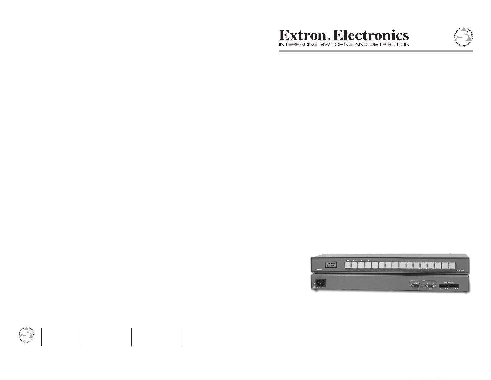
MCP 1000
Remote Control Panel
68-456-01 Rev. C
01 07
Page 2

Precautions
Safety Instructions • English
This symbol is intended to alert the user of important
operating and maintenance (servicing) instructions in
the literature provided with the equipment.
This symbol is intended to alert the user of the
presence of uninsulated dangerous voltage within
the product’s enclosure that may present a risk of
electric shock.
Caution
Read Instructions • Read and understand all safety and operating
instructions before using the equipment.
Retain Instructions • The safety instructions should be kept for future
reference.
Follow Warnings • Follow all warnings and instructions marked on the
equipment or in the user information.
Avoid Attachments • Do not use tools or attachments that are not
recommended by the equipment manufacturer because they may be
hazardous.
Consignes de Sécurité • Français
Ce symbole sert à avertir l’utilisateur que la
documentation fournie avec le matériel contient des
instructions importantes concernant l’exploitation et
la maintenance (réparation).
Ce symbole sert à avertir l’utilisateur de la présence
dans le boîtier de l’appareil de tensions dangereuses
non isolées posant des risques d’électrocution.
Attention
Lire les instructions• Prendre connaissance de toutes les consignes de
sécurité et d’exploitation avant d’utiliser le matériel.
Conserver les instructions• Ranger les consignes de sécurité afi n de pouvoir
les consulter à l’avenir.
Respecter les avertissements • Observer tous les avertissements et consignes
marqués sur le matériel ou présentés dans la documentation utilisateur.
Eviter les pièces de fi xation • Ne pas utiliser de pièces de fi xation ni d’outils
non recommandés par le fabricant du matériel car cela risquerait de poser
certains dangers.
Sicherheitsanleitungen • Deutsch
Dieses Symbol soll dem Benutzer in der im
Lieferumfang enthaltenen Dokumentation
besonders wichtige Hinweise zur Bedienung und
Wartung (Instandhaltung) geben.
Dieses Symbol soll den Benutzer darauf aufmerksam
machen, daß im Inneren des Gehäuses dieses
Produktes gefährliche Spannungen, die nicht isoliert
sind und die einen elektrischen Schock verursachen
können, herrschen.
Achtung
Lesen der Anleitungen • Bevor Sie das Gerät zum ersten Mal verwenden,
sollten Sie alle Sicherheits-und Bedienungsanleitungen genau durchlesen
und verstehen.
Aufbewahren der Anleitungen • Die Hinweise zur elektrischen Sicherheit
des Produktes sollten Sie aufbewahren, damit Sie im Bedarfsfall darauf
zurückgreifen können.
Befolgen der Warnhinweise • Befolgen Sie alle Warnhinweise und
Anleitungen auf dem Gerät oder in der Benutzerdokumentation.
Keine Zusatzgeräte • Verwenden Sie keine Werkzeuge oder Zusatzgeräte,
die nicht ausdrücklich vom Hersteller empfohlen wurden, da diese eine
Gefahrenquelle darstellen können.
Instrucciones de seguridad • Español
Este símbolo se utiliza para advertir al usuario
sobre instrucciones importantes de operación y
mantenimiento (o cambio de partes) que se desean
destacar en el contenido de la documentación
suministrada con los equipos.
Este símbolo se utiliza para advertir al usuario sobre
la presencia de elementos con voltaje peligroso sin
protección aislante, que puedan encontrarse dentro
de la caja o alojamiento del producto, y que puedan
representar riesgo de electrocución.
Precaucion
Leer las instrucciones • Leer y analizar todas las instrucciones de operación y
seguridad, antes de usar el equipo.
Conservar las instrucciones • Conservar las instrucciones de seguridad para
futura consulta.
Obedecer las advertencias • Todas las advertencias e instrucciones marcadas
en el equipo o en la documentación del usuario, deben ser obedecidas.
Evitar el uso de accesorios • No usar herramientas o accesorios que no
sean especifi camente recomendados por el fabricante, ya que podrian
implicar riesgos.
Warning
Power sources • This equipment should be operated only from the power source
indicated on the product. This equipment is intended to be used with a main power
system with a grounded (neutral) conductor. The third (grounding) pin is a safety
feature, do not attempt to bypass or disable it.
Power disconnection • To remove power from the equipment safely, remove all power
cords from the rear of the equipment, or the desktop power module (if detachable),
or from the power source receptacle (wall plug).
Power cord protection • Power cords should be routed so that they are not likely to be
stepped on or pinched by items placed upon or against them.
Servicing • Refer all servicing to qualifi ed service personnel. There are no user-
serviceable parts inside. To prevent the risk of shock, do not attempt to service
this equipment yourself because opening or removing covers may expose you to
dangerous voltage or other hazards.
Slots and openings • If the equipment has slots or holes in the enclosure, these are
provided to prevent overheating of sensitive components inside. These openings
must never be blocked by other objects.
Lithium battery • There is a danger of explosion if battery is incorrectly
replaced. Replace it only with the same or equivalent type recommended by
the manufacturer. Dispose of used batteries according to the manufacturer’s
instructions.
Avertissement
Alimentations• Ne faire fonctionner ce matériel qu’avec la source d’alimentation
indiquée sur l’appareil. Ce matériel doit être utilisé avec une alimentation principale
comportant un fi l de terre (neutre). Le troisième contact (de mise à la terre) constitue
un dispositif de sécurité : n’essayez pas de la contourner ni de la désactiver.
Déconnexion de l’alimentation• Pour mettre le matériel hors tension sans danger,
déconnectez tous les cordons d’alimentation de l’arrière de l’appareil ou du module
d’alimentation de bureau (s’il est amovible) ou encore de la prise secteur.
Protection du cordon d’alimentation • Acheminer les cordons d’alimentation de
manière à ce que personne ne risque de marcher dessus et à ce qu’ils ne soient pas
écrasés ou pincés par des objets.
Réparation-maintenance • Faire exécuter toutes les interventions de réparation-
maintenance par un technicien qualifi é. Aucun des éléments internes ne peut être
réparé par l’utilisateur. Afi n d’éviter tout danger d’électrocution, l’utilisateur ne doit
pas essayer de procéder lui-même à ces opérations car l’ouverture ou le retrait des
couvercles risquent de l’exposer à de hautes tensions et autres dangers.
Fentes et orifi ces • Si le boîtier de l’appareil comporte des fentes ou des orifi ces, ceux-ci
servent à empêcher les composants internes sensibles de surchauffer. Ces ouvertures
ne doivent jamais être bloquées par des objets.
Lithium Batterie • Il a danger d’explosion s’ll y a remplacment incorrect de la batterie.
Remplacer uniquement avec une batterie du meme type ou d’un ype equivalent
recommande par le constructeur. Mettre au reut les batteries usagees conformement
aux instructions du fabricant.
Vorsicht
Stromquellen • Dieses Gerät sollte nur über die auf dem Produkt angegebene
Stromquelle betrieben werden. Dieses Gerät wurde für eine Verwendung mit einer
Hauptstromleitung mit einem geerdeten (neutralen) Leiter konzipiert. Der dritte
Kontakt ist für einen Erdanschluß, und stellt eine Sicherheitsfunktion dar. Diese
sollte nicht umgangen oder außer Betrieb gesetzt werden.
Stromunterbrechung • Um das Gerät auf sichere Weise vom Netz zu trennen, sollten
Sie alle Netzkabel aus der Rückseite des Gerätes, aus der externen Stomversorgung
(falls dies möglich ist) oder aus der Wandsteckdose ziehen.
Schutz des Netzkabels • Netzkabel sollten stets so verlegt werden, daß sie nicht im
Weg liegen und niemand darauf treten kann oder Objekte darauf- oder unmittelbar
dagegengestellt werden können.
Wartung • Alle Wartungsmaßnahmen sollten nur von qualifi ziertem Servicepersonal
durchgeführt werden. Die internen Komponenten des Gerätes sind wartungsfrei.
Zur Vermeidung eines elektrischen Schocks versuchen Sie in keinem Fall, dieses
Gerät selbst öffnen, da beim Entfernen der Abdeckungen die Gefahr eines
elektrischen Schlags und/oder andere Gefahren bestehen.
Schlitze und Öffnungen • Wenn das Gerät Schlitze oder Löcher im Gehäuse aufweist,
dienen diese zur Vermeidung einer Überhitzung der empfi ndlichen Teile im
Inneren. Diese Öffnungen dürfen niemals von anderen Objekten blockiert werden.
Litium-Batterie • Explosionsgefahr, falls die Batterie nicht richtig ersetzt
wird. Ersetzen Sie verbrauchte Batterien nur durch den gleichen oder einen
vergleichbaren Batterietyp, der auch vom Hersteller empfohlen wird. Entsorgen Sie
verbrauchte Batterien bitte gemäß den Herstelleranweisungen.
Advertencia
Alimentación eléctrica • Este equipo debe conectarse únicamente a la fuente/tipo
de alimentación eléctrica indicada en el mismo. La alimentación eléctrica de este
equipo debe provenir de un sistema de distribución general con conductor neutro
a tierra. La tercera pata (puesta a tierra) es una medida de seguridad, no puentearia
ni eliminaria.
Desconexión de alimentación eléctrica • Para desconectar con seguridad la acometida
de alimentación eléctrica al equipo, desenchufar todos los cables de alimentación
en el panel trasero del equipo, o desenchufar el módulo de alimentación (si fuera
independiente), o desenchufar el cable del receptáculo de la pared.
Protección del cables de alimentación • Los cables de alimentación eléctrica se deben
instalar en lugares donde no sean pisados ni apretados por objetos que se puedan
apoyar sobre ellos.
Reparaciones/mantenimiento • Solicitar siempre los servicios técnicos de personal
califi cado. En el interior no hay partes a las que el usuario deba acceder. Para evitar
riesgo de electrocución, no intentar personalmente la reparación/mantenimiento
de este equipo, ya que al abrir o extraer las tapas puede quedar expuesto a voltajes
peligrosos u otros riesgos.
Ranuras y aberturas • Si el equipo posee ranuras o orifi cios en su caja/alojamiento,
es para evitar el sobrecalientamiento de componentes internos sensibles. Estas
aberturas nunca se deben obstruir con otros objetos.
Batería de litio • Existe riesgo de explosión si esta batería se coloca en la posición
incorrecta. Cambiar esta batería únicamente con el mismo tipo (o su equivalente)
recomendado por el fabricante. Desachar las baterías usadas siguiendo las
instrucciones del fabricante.
FCC Class A Notice
Note: This equipment has been tested and found to comply with the limits for a
Class A digital device, pursuant to part 15 of the FCC Rules. These limits are designed
to provide reasonable protection against harmful interference when the equipment is
operated in a commercial environment. This equipment generates, uses and can radiate
radio frequency energy and, if not installed and used in accordance with the instruction
manual, may cause harmful interference to radio communications. Operation of this
equipment in a residential area is likely to cause harmful interference, in which case the
user will be required to correct the interference at his own expense.
Note: This unit was tested with shielded cables on the peripheral devices. Shielded
cables must be used with the unit to ensure compliance.
Extron’s Warranty
Extron Electronics warrants this product against defects in materials and workmanship
for a period of three years from the date of purchase. In the event of malfunction during
the warranty period attributable directly to faulty workmanship and/or materials,
Extron Electronics will, at its option, repair or replace said products or components,
to whatever extent it shall deem necessary to restore said product to proper operating
condition, provided that it is returned within the warranty period, with proof of
purchase and description of malfunction to:
USA, Canada, South America, Europe, Africa, and the Middle East:
and Central America: Extron Electronics, Europe
Extron Electronics Beeldschermweg 6C
1001 East Ball Road 3821 AH Amersfoort
Anaheim, CA 92805, USA The Netherlands
Asia: Japan:
Extron Electronics, Asia Extron Electronics, Japan
135 Joo Seng Road, #04-01 Kyodo Building
PM Industrial Bldg. 16 Ichibancho
Singapore 368363 Chiyoda-ku, Tokyo 102-0082
Japan
This Limited Warranty does not apply if the fault has been caused by misuse, improper
handling care, electrical or mechanical abuse, abnormal operating conditions or nonExtron authorized modifi cation to the product.
If it has been determined that the product is defective, please call Extron and ask for an
Applications Engineer at (714) 491-1500 (USA), 31.33.453.4040 (Europe), 65.6383.4400
(Asia), or 81.3.3511.7655 (Japan) to receive an RA# (Return Authorization number). This
will begin the repair process as quickly as possible.
Units must be returned insured, with shipping charges prepaid. If not insured, you
assume the risk of loss or damage during shipment. Returned units must include the
serial number and a description of the problem, as well as the name of the person to
contact in case there are any questions.
Extron Electronics makes no further warranties either expressed or implied with respect
to the product and its quality, performance, merchantability, or fi tness for any particular
use. In no event will Extron Electronics be liable for direct, indirect, or consequential
damages resulting from any defect in this product even if Extron Electronics has been
advised of such damage.
Please note that laws vary from state to state and country to country, and that some
provisions of this warranty may not apply to you.
Page 3

ᅝܼ乏ⶹ噝Ё᭛
⊼ᛣ
䯙䇏䇈ᯢк
ֱᄬ䇈ᯢк
䙓ܡ䗑ࡴ
䄺
ᢨᥝ⬉⑤
⬉⑤㒓ֱᡸ
㓈ᡸ
䗮亢ᄨ
䫖⬉∴
ᅝܼ乏ⶹ噝Ё᭛
䖭Ͼヺোᦤ⼎⫼᠋䆹䆒⫼᠋ݠЁ
ⱘ᪡㓈ᡸ䇈ᯢDŽ
䖭Ͼヺো䄺⫼᠋䆹䆒ᴎݙᲈ
䴆ⱘ䰽⬉ˈ᳝㾺⬉䰽DŽ
⊼ᛣ
䯙䇏䇈ᯢк
噝⫼᠋Փ⫼䆹䆒ࠡᖙ乏䯙䇏ᑊ⧚㾷
᳝ᅝܼՓ⫼䇈ᯢDŽ
ֱᄬ䇈ᯢк
噝⫼᠋ᑨֱᄬᅝܼ䇈ᯢкҹᇚᴹՓ⫼DŽ
䙉ᅜ䄺噝⫼᠋ᑨ䙉ᅜѻક⫼᠋ᣛϞⱘ᠔᳝
ᅝܼ᪡䇈ᯢDŽ
䙓ܡ䗑ࡴ
噝ϡ㽕Փ⫼䆹ѻકଚ≵᳝㤤ⱘᎹ
䗑ࡴ䆒ˈҹ䙓ܡ䰽DŽ
䄺
⬉⑤⬉⑤噝䆹䆒া㛑Փ⫼ѻકϞᯢⱘ⬉⑤DŽ䆒ᖙ⫼᳝
ഄ㒓կ⬉㋏㒳կ⬉DŽϝᴵ㒓˄ഄ㒓˅ᰃᅝ䆒ᮑˈϡ㛑ϡ
⫼䏇䖛DŽ
噝ЎᅝܼഄҢ䆒ᢨᥝ⬉⑤ˈ䇋ᢨᥝ᠔᳝
ᢨᥝ⬉⑤
ৢḠ䴶⬉⑤ⱘ⬉⑤㒓ˈӏԩࠄᏖ⬉㋏㒳
⬉⑤㒓DŽ
噝ཹᏗ㒓ˈ䙓ܡ㹿䏽䏣ˈ䞡⠽DŽ
⬉⑤㒓ֱᡸ
噝᠔᳝㓈ׂᖙ乏⬅䅸䆕ⱘ㓈ׂҎ䖯㸠DŽ䆒
㓈ᡸ
䚼≵᳝⫼᠋ৃҹᤶⱘ䳊ӊDŽЎ䙓ܡߎ⦄㾺⬉
ϡ㽕㞾Ꮕ䆩ᠧᓔ䆒Ⲫᄤ㓈ׂ䆹䆒DŽ
噝᳝ѯ䆒ᴎϞ᳝䗮亢ῑᄨˈᅗӀᰃ⫼
䗮亢ᄨ
䰆ℶᴎݙᬣᛳܗӊ䖛⛁DŽϡ㽕⫼ӏԩϰ㽓ᣵԣ䗮亢ᄨDŽ
噝ϡℷ⹂ⱘᤶ⬉∴Ӯ᳝⟚⚌ⱘ䰽DŽᖙ乏Փ
䫖⬉∴
Ϣᆊ㤤ⱘⳌৠⳌ䖥ൟোⱘ⬉∴DŽᣝ✻⫳ѻⱘ
䆂໘⧚ᑳᓗ⬉∴
DŽ
Page 4

Precautions
Table of Contents
Chapter One • Introduction ................................................... 1-1
About this Manual .................................................................... 1-2
About the MCP 1000 ................................................................. 1-2
Features ........................................................................................ 1-3
Button functions .................................................................... 1-3
Simple Instruction Set (SIS) ................................................... 1-3
Mounting options .................................................................. 1-3
MCP 1000 as part of a Matrix 3200/6400 system ................ 1-4
Comm-link requirements ....................................................... 1-4
Chapter Two • Installation ..................................................... 2-1
Mounting the MCP 1000 ......................................................... 2-2
Tabletop use ........................................................................... 2-2
Rack mounting ....................................................................... 2-2
UL requirements ............................................................... 2-2
Mounting instructions ..................................................... 2-3
Rear Panel Connections ........................................................... 2-3
RS-232 connectors (primary) ................................................. 2-4
Comm-link connectors (primary or secondary) .................... 2-5
Making cables ................................................................... 2-5
Extron’s Plenum Comm-Link cable .................................. 2-7
Changing the Front Panel Button Labels ........................... 2-8
Using the Button Label Generator ....................................... 2-8
Installing the software .......................................................... 2-8
Using the software ................................................................ 2-8
Chapter Three • Operation ..................................................... 3-1
Front Panel Features ................................................................. 3-2
Application Examples ............................................................... 3-3
Primary applications (RS-232) ................................................. 3-3
Audio-video switcher — SIS command: i! ...................... 3-3
Video switcher — SIS command: i& ................................ 3-4
Audio switcher — SIS command: i$ ................................ 3-4
Output (matrix) — SIS command: i*o! ........................... 3-4
Preset (matrix) — SIS command: p. ................................. 3-4
Secondary applications (comm-link) ..................................... 3-5
Daisy-chain confi guration ............................................... 3-5
Star confi guration ............................................................ 3-6
Star/daisy-chain confi guration ........................................ 3-6
Primary/secondary applications (RS-232/comm-link) ......... 3-7
MCP 1000 • Table of Contents
i
Page 5

Table of Contents, cont’d
Setting Up the Operation Mode ........................................... 3-8
LCD display ............................................................................. 3-8
Title screen display ........................................................... 3-8
Testing lights .................................................................... 3-8
Left-right selection arrows .............................................. 3-8
Using setup mode .................................................................. 3-8
Mode examples ................................................................ 3-9
Preset mode ................................................................... 3-9
Switcher mode .............................................................. 3-9
Output mode (matrix) .................................................. 3-9
Room mode ................................................................. 3-10
Setup fl ow charts ........................................................... 3-10
Appendix A • Specifi cations, Part Numbers, and
Accessories ........................................................................................A-1
Specifi cations ..............................................................................A-2
Included Parts .............................................................................A-3
Cables ............................................................................................A-3
MCP 1000 Remote Control Panel
Chapter One
1
All trademarks mentioned in this manual are the properties of their respective owners.
68-456-01 C
ii
MCP 1000 • Table of Contents
Introduction
About this Manual
About the MCP 1000
Features
01 07
Page 6

Introduction
About this Manual
This manual contains information about the Extron MCP 1000
primary and secondary remote control panels — the MCP 1000P
and the MCP 1000S — and provides information on how to
operate and confi gure them.
In this manual, "MCP 1000" is used to refer to either unit. The
terms "preliminary," "secondary," "MCP 1000P," and
"MCP 1000S" are used to refer specifi cally to one unit or the other.
About the MCP 1000
The MCP 1000 is a multipurpose control panel that can be part
of an A/V presentations system, or dedicated to controlling a
particular Extron device.
There are two versions of the MCP 1000:
• MCP 1000P (Primary), which includes an RS-232 port and
comm-link voltage
• MCP 1000S (Secondary), which has neither an RS-232
port nor comm-link voltage
A primary can also function as a secondary, if necessary.
The MCP 1000P can control any Extron SW switcher, system
switcher, or matrix switcher that uses Extron’s Simple
Instruction Set (SIS™) commands.
The MCP 1000 features one-button crosspoint operation and
one-button operation per preset for global and room presets.
An MCP 1000P can receive RS-232 commands from a host
computer and can send them to a device that accepts Extron’s
SIS commands. It can also receive signals on the comm-link
port, translate them to SIS commands, and send them to a
matrix switcher or simple switcher.
A secondary MCP 1000 uses a 5-pole, 5 mm comm-link
connection to communicate with either an MCP 1000 primary
or a Matrix 3200/6400 switching system. This application
can include up to 64 units mixed with MCP 1000 panels and
MKP 1000 keypads.
The MCP operating modes include:
• Remote switching control for an Extron switcher or a
matrix switcher (with MCP 1000 primary only)
• Input selection for a switcher
• Global presets (with matrix switchers)
• Room presets (with Matrix 3200/6400 only).
Although secondary units must be given a unique address
(1 – 64) within a system, redundant units can be set up to
allow identical control from more than one location.
Features
• Front panel includes 16 large, illuminated push buttons.
• Graphic/text inserts are provided for button assignments.
• Internal power supply, 100 VAC – 240 VAC, 50/60 Hz
• Works with multiple MCP 1000 and MKP 1000 units.
• Controls any SIS-compatible switcher.
• Includes brackets for rack, table, or shelf mounting.
• Enclosure is 1U high and 5.0" deep.
• LCD panel displays the function name and number.
Button functions
The fi rst four buttons on the left are used during setup. During
normal operation, however, they function the same as the other
12 buttons — as program or selection buttons. The MCP 1000
can be a control panel for many Extron products.
Simple Instruction Set (SIS)
The primary MCP 1000P is preprogrammed with SIS
commands in several categories. After the unit has been
configured for an application, appropriate SIS commands are
issued when a button is pressed. Such commands include
selecting an input number, a preset number, or a room preset
number. For example, if the unit is set up to work with a
matrix switcher as output 5 to handle inputs 1 through 16,
pressing MCP 1000 panel button 9 selects (ties) input 9 to
output 5. See chapter 3, "Operation," for detailed examples
with illustrations.
Any MCP 1000S secondary unit connected to a primary
communicates through the comm-link ports. The primary unit
receives the comm-link command from a secondary translates it
to an SIS command, and sends it out through the RS-232 port to
the device being controlled.
Mounting options
The MCP 1000 comes with a set of brackets for mounting the
unit on a rack, or under or through a shelf, table, or podium.
MCP 1000 panels can be located in various places throughout a
business or educational complex.
1-2 1-3
MCP 1000 • Introduction
MCP 1000 • Introduction
Page 7
Introduction, cont’d
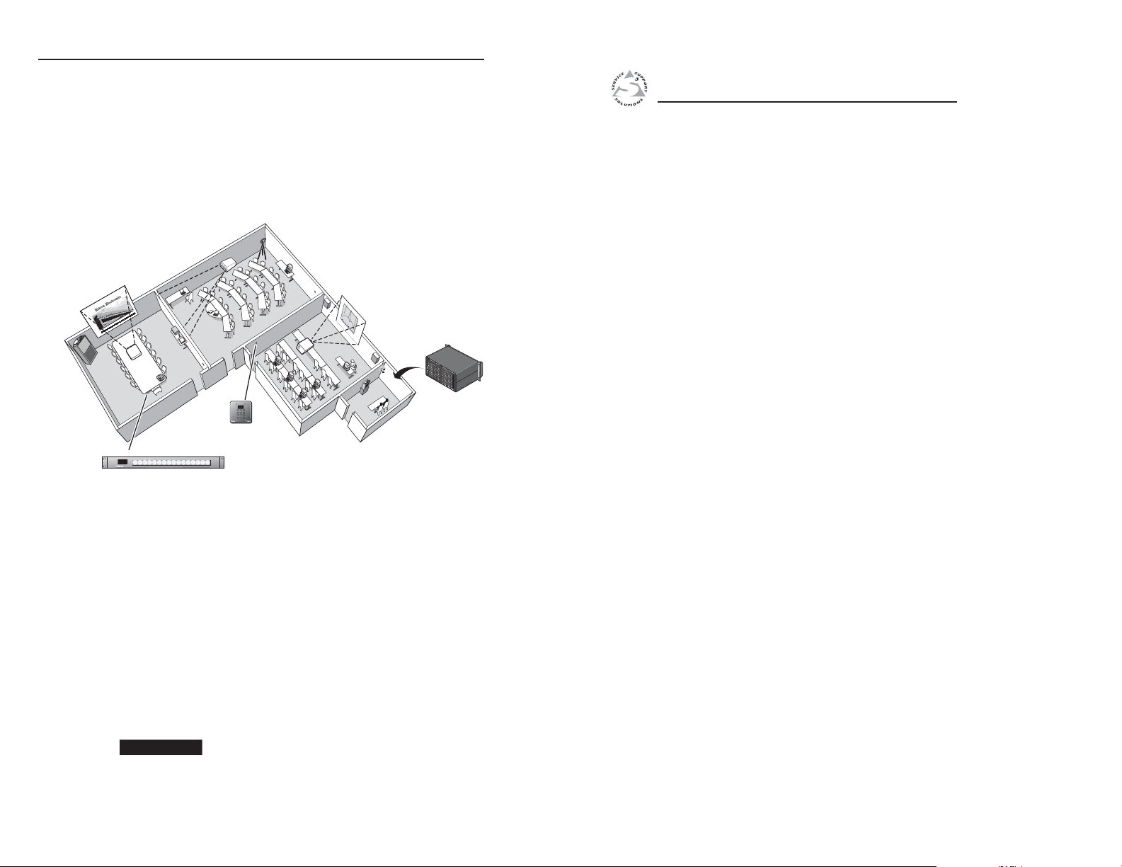
MCP 1000 as part of a Matrix 3200/6400 system
When used with an Extron Matrix 3200/6400 switcher, the
MCP 1000 has the same functions as the MKP 1000 Remote
Keypad. For this type of installation, the MCP 1000 panels are
hard-wired to a Matrix 3200/6400 switcher, and they can be
mixed with MKP 1000 keypads. For additional information,
see the MKP 1000 User’s Manual. As with the MKP 1000, the
status of MCP 1000 units can be displayed on the front panel
(FPC 1000) of the Matrix 3200/6400.
Demo
Room
R
o
llo
ff
U
n
e
v
R
e
n
e
F
s
p
o
re
n
q
s
u
e
e
n
c
y
R
o
llo
ff
20
10
50
100
8
6
1000
Frequency (Hz)
10k
Computer
4
75k
100k
2
Output
Voltag
Training Room
e
Videoconference
Room
A
B
C
D
E
A
B
C
D
E
IN
O
U
T
A
C
P
F
O
U
W
S
E
E
R
:
2
5
0
V
Conference
Room
Welcome to
MENU NEXT
Extron
MCP 1000
Remote Control Panel
s
n
ic
ro
n
t
o
x
tr
E
c
le
E
123
456
789
VIEW ENTER
0
Extron
MKP 1000
Remote Keypad
MCP 1000
B
M
E
4
A
D
D
R
E
S
S
MKP COMM.
IN
P
U
TS
A
N
A
H
M
E
A
I
M
D
,
E
C
I
N
A
U
S
A
IN
BME COMM.
I
N
P
U
IN
T
5
O
.
0
A
U
T
T
T
P
U
T
S
DISCONNECT POWER CORD BEFORE SERVICING
100-240V 0.5A MAX 50/60Hz
1
8
9
1
6
1
7
- 2
4
2
5
3
2
3
3
- 4
0
4
1
4
8
4
9
5
6
5
7
6
4
Extron
Matrix 6400
Matrix Switcher
MCP 1000 Remote Control Panel
Chapter Two
2
Using the MCP 1000 with an MKP 1000 and a
Matrix 3200/6400 switcher.
Comm-link requirements
The maximum total cable length in a comm-link system
is 1000 feet (305 meters). It doesn’t matter whether the
confi guration is a daisy-chain, a star, or a combination of both.
The maximum number of MKP 1000 and MCP 1000 units in one
system is 64.
Through the comm-link port, an MCP 1000P (primary) unit
supplies voltage to MKP 1000 units. Matrix 3200/6400 BMEs
(Basic Module Enclosures) also supply voltage through the
comm-link ports for MKP 1000s.
CAUTION
1-4
MCP 1000 • Introduction
Installation
Mounting the MCP 1000
Rear Panel Connections
Changing the Front Panel Button Labels
Using the Button Label Generator
Damage may occur if more than one voltage source
is connected to a system. See page "Comm-link
connectors (primary or secondary)" in chapter 2,
"Installation," for more details.
Page 8

Installation
Mounting the MCP 1000
The MCP is 1U high by 17.5" wide by 5" deep. It can be placed
on a table or other furniture, or it can be mounted in a rack
using mounting brackets (“rack ears”).
Tabletop use
Four self-adhesive rubber feet are included with the MCP 1000.
For tabletop use, attach one foot to each corner of the bottom
side of the unit and place the MCP in the desired location.
Rack mounting
The MCP can optionally be mounted in a rack with the supplied
MBD 149 rack mounting kit (part #70-077-03).
UL requirements
The following Underwriters Laboratories (UL) requirements
pertain to the installation of the MCP 1000 into or onto a rack.
1. Elevated operating ambient — If the equipment is
installed in a closed or multi-unit rack assembly, the
operating ambient temperature of the rack environment
may be greater than room ambient. Therefore, consider
installing the equipment in an environment compatible
with the maximum ambient temperature (Tma) specifi ed
by the manufacturer.
2. Reduced air fl ow — Installation of the equipment in a rack
should be such that the amount of air fl ow required for
safe operation of the equipment is not compromised.
3. Mechanical loading — Mounting of the equipment in
the rack should be such that a hazardous condition is not
achieved due to uneven mechanical loading.
4. Circuit overloading — Consideration should be given to
the connection of the equipment to the supply circuit and
the effect that overloading of the circuits might have on
over current protection and supply wiring. Appropriate
consideration of equipment nameplate ratings should be
used when addressing this concern.
5. Reliable earthing (grounding) — Reliable earthing
of rack-mounted equipment should be maintained.
Particular attention should be given to supply connections
other than direct connections to the branch circuit (such as
the use of power strips).
Mounting instructions
Follow these steps to rack mount the MCP 1000:
1. Attach the mounting brackets to the unit using eight of the
machine screws supplied with the mounting kit.
2. Insert the unit into the rack and align the holes in the
mounting brackets with the holes in the rack. Use four of
the supplied machine screws to attach the brackets to the
rack.
#8 Screws
(4 Places
Each Side)
Rack mounting the MCP 1000
Rear Panel Connections
There are many ways to connect the MCP 1000 to other
products. However, there are two general applications:
one using RS-232, and the other using the comm-link port.
In some applications, both of these connectors are used.
Chapter 3, "Operations," includes illustrated examples of several
applications.
1.5A MAX.
100-240V 50/60Hz
RS-232
Rack Mounting
Bracket
COMM - LINK PORT
HOSTSWITCHER
ED
CBA EDCBA
1
2 3 5
4
MCP 1000 rear panel connectors
2-2 2-3
MCP 1000 • Installation
MCP 1000 • Installation
Page 9

Installation, cont’d
RS-232 connectors (primary)
Power connector — Plug the provided power cord into this
a
connector to connect the MCP to a 100-250 VAC, 50/60 Hz
power source.
Switcher — Use this 9-pin connector for communication
b
between the MCP 1000 and a comm port on the switcher that
will be controlled by the MCP 1000.
Host — Use this 9-pin connector for communication between
c
the MCP 1000 and a comm port on the RS-232 controlling device
or a computer with Extron’s control software for Windows
installed.
CAUTION
The RS-232 connector uses the following pin assignments:
Pin Description
1
2
3
4
5
6
7
8
9
The protocol is 9600 baud, 8-bit, 1 stop bit, no parity, and no
fl ow control.
The illustration on the next page shows a host controller and a
switcher connected to the RS-232 ports on the MCP 1000.
Do not use delay or pause characters (commands
that delay execution of the next SIS command) in
RS-232 commands. Use contiguous SIS characters.
Not used
Transmit data
Receive data
Not used
Signal ground
Not used
Not used
Not used
Not used
RS-232
Host
Control
AUD. VID.
SWITCHER
AUD.VID.
SWITCHER
MENU NEXT
1
Switcher to be controlled
4
56
23
7
MCP 1000 (primary)
89
10
MCP 1000, host controller, and switcher
Comm-link connectors (primary or secondary)
and e Comm-link panel connectors — Connect a matrix
d
switcher or another (primary or secondary) MCP to these 5-pole,
5 mm male connectors. The MCP 1000 includes two female
connectors for making cables.
Although comm-link connections can be used in a primary
application, the typical application is a large matrix system,
such as a Matrix 6400. This can include multiple MCP 1000
units,
as well as MKP 1000 units, intermixed. See the application
examples illustrated in chapter 3, "Operations."
Making cables
Choose a cable such as AMX/Panja’s Axlink, Crestron’s Cresnet,
or Extron’s Plenum Comm-Link cable. The wire specifi cations
for comm-link cable are on page 2-5. After running the cables,
follow the procedure below to install the connectors.
The appropriate connectors are shipped with each device:
MCP 1000 — Use 5 mm connectors (Extron part number
10-163-13).
MKP 1000 — Use 3.5 mm connectors (Extron part number
10-319-10).
Matrix 3200/6400 primary BME — Use 5 mm connectors
(Extron part number 10-163-13).
CAUTION
Do not connect both a Matrix 3200/6400 BME and
an MCP 1000P (primary) unit on the same commlink connection. Also, do not connect more than
one primary on the same comm-link connection.
Both of theses units supply voltage to the commlink ports on pins A and B. Connect these pins
to only one power source. This does not apply to
MCP 1000S (secondary) units.
MCP 1000
2-4
MCP 1000 • Installation
MCP 1000 • Installation
2-5
Page 10

Installation, cont’d
Cables must be made with the appropriate connector on each
end. Regardless of the connector that is being used, the wiring
must be one-to-one (for example, red-to-red and A-to-A).
CAUTION
Damage may occur to circuits if cable wire
assignments are not the same on both ends.
The total cable length for connecting MCP 1000s and
MKP 1000s to a matrix system must not exceed 1000 feet
(305 meters).
To attach connectors to the cables,
1. Trim approximately 1.5 inches of the cable jacket to expose
the four insulated wires and a bare drain (ground) wire
(silver colored).
Trimming the cable jacket
2. Cut off and discard the foil shield.
3. Strip 0.25 inches of insulation from each of the four wires.
4. Twist the strands of the black
wire, insert it into the opening
that corresponds to pin E, and
tighten its captive screw. (See the
illustration at right.)
5. Twist the strand of the drain
1
wire, insert it into position D, and
tighten its captive screw.
6. Connect the remaining wires in
3.5 mm captive
screw connector on
MCP 1000
the same way (for this example,
white, violet, and red).
COMM-LINK PORT
ED
CBA EDCBA
5 mm captive
screw connector
Wiring the 5 mm captive screw plugs
7. Choose the appropriate captive screw connector and repeat
steps 1 through 6 for each cable end.
Both types of captive screw connectors use a “moving cage” to
damp the wires, without the need for soldering.
Extron’s Plenum Comm-Link cable
Extron’s Plenum Comm-Link cable was designed for use with
the MCP 1000 and MKP 1000. If another cable will be used, it
must meet the following specifi cations:
A (red) — 18 AWG
B (violet or blue) — 22 AWG (grouped and shielded)
C (white) — 22 AWG
D (drain) — 24 AWG
E (black) — 18 AWG
See appendix A, "Specifi cations, Part Numbers, and
Accessories," for a list of Extron cable part numbers.
2-6
MCP 1000 • Installation
MCP 1000 • Installation
2-7
Page 11
Installation, cont’d
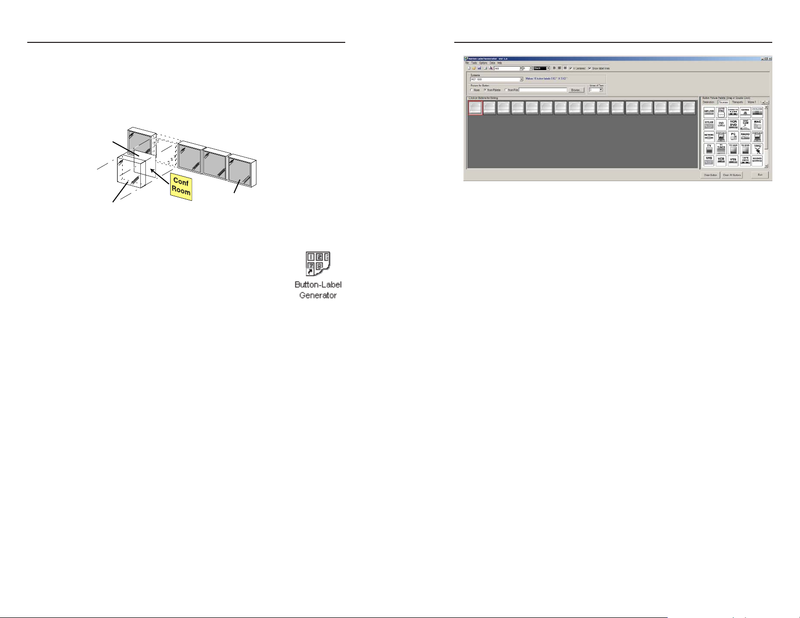
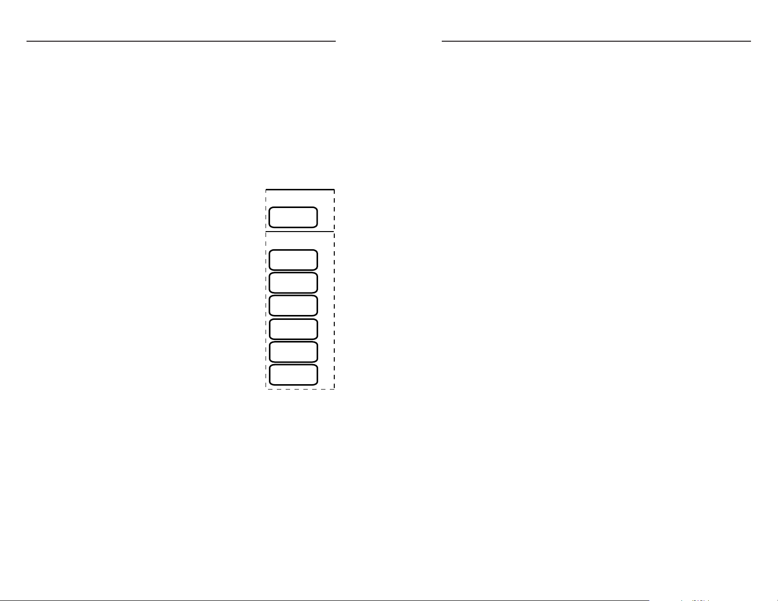
Changing the Front Panel Button Labels
The 16 buttons on the MCP 1000 are not marked for operation.
You can remove the button caps to reveal a label plate (see the
fi gure below). Remove each cap and insert a label (icon or text)
for each button to identify its assignment. You can use the
Extron Button Label Generator (page 2-8) to produce labels.
Legend
Plate
Clear Cover
Replacing a button label
You can print labels on transparent or translucent material, and
then cut them from a sheet. Also, see the colored
button caps listed in the parts list in the appendix.
Insert identification tag.
Key Cap
Using the Button Label Generator
Installing the software
The program is provided on a CD-ROM, and you can run it
from the CD drive. However, it is usually more convenient to
load and run the program from the hard drive.
To install the Button Label Generator program from the CDROM to the hard drive, run SETUP.EXE from the CD and
follow the instructions that appear on the screen. The program
occupies approximately 0.5 MB of hard-drive space.
By default, the Windows installation program creates a
C:\BUTTONS directory, and it places an icon (Button-Label
Generator) into a group or folder named “Extron Electronics.”
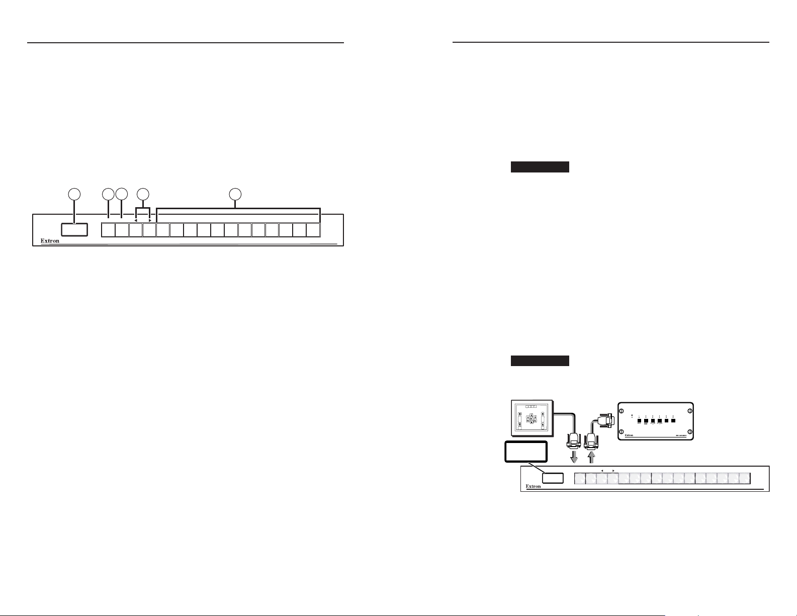
Extron’s Button Label Generator window
3. Using normal Windows controls, you can create and print
labels that can be placed in the button panel inserts on the
MCP 1000 front panel.
For more information about using the program, you can access
the Button Label Generator online help by selecting Show Help
from the Help menu on the main screen.
Using the software
1. To start the Button Label Generator program, double-click
2. Under System selection, choose MCP 1000. The Extron’s
2-8
MCP 1000 • Installation
on the Button Label Generator icon (shown at the left) in
the Extron Electronics group or folder, and click OK when
prompted.
Button Label Generator window appears (see the fi gure on
the next page).
MCP 1000 • Installation
2-9
Page 12

Installation, cont’d
MCP 1000 Remote Control Panel
Chapter Three
3
2-10
Operation
Front Panel Features
Application Examples
Setting Up the Operation Mode
MCP 1000 • Installation
Page 13
Operation
Front Panel Features
The buttons on the MCP 1000 front panel enable you to set up
and operate the MCP and to control a connected switcher.
N
MCP 1000 front panel
LCD window — This screen displays messages, menu
a
information, and selections you make by pressing front panel
buttons in different operating modes. (See “Setting Up the
Operation Mode,” later in this chapter, for more information.)
Menu button — In setup mode, press this button to access the
b
MCP’s menu system and step through the menus.
In the operating modes, this button becomes another selection
button.
Next button — In setup mode, after selecting a menu using
c
the Menu button, press the Next button to step through the
submenus.
In the operating modes, this button becomes another selection
button.
Right and left arrow buttons — In Setup mode, these buttons
d
let you make selections from the current submenu that you
accessed by pressing the Next button. From the submenus, you
can select the operating mode, a preset, the IP address, etc.
In the operating modes, these buttons become selection buttons.
Selection buttons — Press these buttons to issue SIS commands
e
to select an audio or video input, an output, or a preset,
depending on the operating mode specifi ed at setup. (These
buttons are disabled when the MCP is in setup mode.)
In setup mode, the Menu, Next, W, and X buttons (
, and d in the illustration below) provide access to
c
the menus and submenus used for setting up the MCP.
When the MCP is in one of the operating modes (switcher,
output, room, or preset), these buttons function the same
as the other 12 selection buttons (
See “Using setup mode,” later in this chapter, for more
information.
3
4
MENU NEXT
in the illustration).
e
51 2
b
MCP 1000
Application Examples
This section shows some examples of how the MCP 1000 can
be used to perform various functions with a variety of devices.
,
Primary applications (RS-232)
In view mode, the LCD window displays a title for the type
of operation (see "Title screen display," later in this chapter).
Numbers, names, and symbols can be created and inserted
in the button caps to identify the function of each button
(see "Changing the Front Panel Button Labels" in chapter 2,
"Installation").
CAUTION
For each confi guration, a primary sends out a specifi c SIS
command for each button that is pressed. If the primary has
any slaves attached by comm-link, the primary translates
the comm-link signals to SIS commands and sends them to
the device being controlled. The following examples
include the SIS command, in which i is the input number, o
is the output number, and p is the preset number.
CAUTION
Audio-video switcher — SIS command: i!
AUD.VID.
SWITCHER
AUD.VID.
SWITCHER
Do not connect both a Matrix 3200/6400 BME and
an MCP 1000P (primary) unit on the same commlink connection. Also, do not connect more than
one primary on the same comm-link connection.
Both of theses units supply voltage to the commlink ports on pins A and B. Connect these pins
to only one power source. This does not apply to
MCP 1000S (secondary) units.
Do not use delay or pause characters in RS-232
commands. Use contiguous SIS commands.
RS-232
Host
Control
Switcher to be controlled
MENU NEXT
1
23
4
56
MCP 1000 Primary
MCP 1000P, SW6 switcher, and host computer
Pressing a panel button generates an SIS command to switch
audio and video for the corresponding button. For example,
press panel button 5 for input 5. If the switcher has fewer than
16 inputs, the MCP 1000 still sends out commands for unused
buttons, which may cause an error response from the switcher.
MCP 1000
3-2 3-3
MCP 1000 • Operation
MCP 1000 • Operation
Page 14

Operation, cont’d
Video switcher — SIS command: i&
This confi guration is the same as for the audio-video switcher
shown on the previous page, except that only video signals are
switched. This is called "audio breakaway."
Audio switcher — SIS command: i$
This confi guration is the same as for the audio-video switcher,
except that only audio signals are switched. This is called
"audio breakaway."
Audio breakaway is not available in matrix mode.
In the illustration below, the primary switches video only and
the secondary switches audio only. In this confi guration, the
two units are operationally identical, even though one is a
primary and one is a secondary. The primary could have been
set for audio, and the secondary could have been set for video.
RS-232 Control
MENU NEXT
MCP 1000 Secondary set for Switcher
MENU NEXT
MCP 1000 Primry
MCP 1000P, MCP 1000S, and System 10 Plus
Output (matrix) — SIS command: i*o!
Depending on the size of the matrix switcher, the MCP 1000 can
be set up for one of 64 output numbers. In output mode, an
MCP 1000 acts like a switcher for a specifi c output number on
the matrix. For example, if the MCP 1000 is set up for output 5
and panel button 3 is pressed, the matrix ties input 3 to output 5.
Preset (matrix) — SIS command: p.
A preset is a set of ties, inputs to outputs, that has been made
and stored previously. Depending on the size of the matrix
switcher, the MCP 1000 can be set up for presets 1 through 16,
or 17 through 32. Pressing an MCP button recalls (activates) a
preset in the matrix.
MCP 1000
MCP 1000
RS-232
Comm-Link
Control
Control
2
1
2
1
3
MAV Plus 1616 A (Matrix)
INPUTS
4
7
3
6
5
10
9
8
4
5
11
7
6
10
9
8
11
OUTPUTS
using MCP 1000s
MENU NEXT
MCP 1000 Primary set for Presets 1-16
MENU NEXT
MCP 1000 Secondary set for Output 1
Next (more MCP 1000s or MKP 1000s)
Output mode and preset mode on a MAV Plus 1616 A
Secondary applications (comm-link)
CAUTION
A secondary unit has no RS-232 port; it communicates through
the comm-link ports. This allows it to be used in a
Matrix 3200/6400 system, either as a single control panel or with
other MCP 1000 and MKP 1000 units.
An MCP 1000S must always connect to an MCP 1000P or to a
Matrix 3200/6400 BME. See "Output (matrix) — SIS command:
i*o!" and "Preset (matrix) — SIS command: p.", earlier in this
chapter, for two examples of secondary units used with a primary
unit.
A secondary sends signals by comm-link to the MCP 1000P or
BME. An MCP 1000P translates those signals to SIS commands
and sends them to the controlled device. A primary BME sends
control signals to the appropriate BMEs in the Matrix 3200/6400
system.
Daisy-chain confi guration
A daisy-chain confi guration saves cable by allowing signals
from units that are far away to be passed serially through
units that are near the primary unit. MCP 1000 and MKP 1000
units can be mixed in the same configuration.
Do not connect both a Matrix 3200/6400 BME and
an MCP 1000P (prinary) unit on the same commlink connection. Also, do not connect more than
one primary on the same comm-link connection.
Both of theses units supply voltage to the commlink ports on pins A and B. Connect these pins
to only one power source. This does not apply to
MCP 1000S (secondary) units.
13
12
14
16
15
13
12
14
15
MCP 1000
CONTROL
I/O
AUDIO
ESC
ENTER PRESET
VIDEO
MCP 1000
VIEW
AV MATRIX SWITCHER WITH IP LINK™
MAV PLUS SERIES
16
3-4
MCP 1000 • Operation
MCP 1000 • Operation
3-5
Page 15

Operation, cont’d
MKP 1000
next (up to 64 units, total)
Daisy-chain confi guration
Star confi guration
A star confi guration uses separate, parallel cables to connect
secondary units to an MCP 1000P or to a BME. This configuration is
recommended when secondary units are located in opposite
directions from the primary unit. See the figure below.
more
units
more
units
MCP 1000 Secondary
MENU NEXT
MCP 1000 Secondary
MENU NEXT
more
units
MCP 1000 Secondary
MCP 1000 Secondary
MENU NEXT
Matrix
MCP 1000 Secondary
MENU NEXT
Matrix
MENU NEXT
Daisy-chain configuration
MCP 1000
MCP 1000
Star configuration
MCP 1000
MCP 1000
MCP 1000
MKP 1000
3.5 mm
connectors
5 mm
connectors
MENU NEXT
5 mm captive
screw connector
2nd 5 mm
receptacle for
another daisy-
chain or star
configuration
MCP 1000
RGB
MUTE
AUDIO
MUTE
FPC-1000
POWER SUPPLIES COMMUNICATIONS
SYSTEM
-
+
STATUS
V
V
MKP
RS232 BME
PRIMARY
TX
MATRIX 6400
REDUNDANT RX
WIDEBAND VIDEO
DIAGNOSTICS
MCP 1000
next (up to 64 units, total)
Star/daisy-chain confi guration
Primary/secondary applications (RS-232/comm-link)
Some applications can use an MCP 1000P with an RS-232 host.
The fi gure below shows an example.
MKP 1000
3.5 mm
connectors
Comm-Link
(MKP) control
next (up to 64 units, total)
RS-232
control
MENU NEXT
MCP 1000
RS-232
PC Windows Control
Primary/secondary application
RGB
MUTE
AUDIO
MUTE
FPC-1000
POWER SUPPLIES COMMUNICATIONS
SYSTEM
STATUS
-
+
V
V
RS232 BME
MKP
PRIMARY
TX
REDUNDANT RX
MATRIX 6400
WIDEBAND VIDEO
DIAGNOSTICS
MCP 1000
3-6
Star confi guration
Star/daisy-chain confi guration
Depending on the physical layout of the confi guration, you
can cable the application in combinations of stars and daisy
chains, as long as the total cable length does not exceed 1000 feet
(305 meters). See the fi gure on the next page.
MCP 1000 • Operation
MCP 1000 • Operation
3-7
Page 16
Operation, cont’d
s
Setting Up the Operation Mode
Review the application examples for the mode in which your
MCP 1000 will be used, and then set up the unit following the
fl ow charts at the end of this chapter.
The following sections describe how the front panel operates.
LCD display
Before using the panel buttons and LCD menus, read the
following descriptions.
Title screen display
When the MCP 1000 is powered up and
operational, a title screen appears in the
LCD display. If view mode is off, the
product name appears. If view mode is on,
a title indicates the operation mode. The
example on the right shows output 3. If
the MCP 1000 is confi gured as a room or as
an output device, then the selected room
number or output number is also displayed.
In preset mode, the preset range numbers
are also displayed.
Testing lights
If the panel buttons light one by one, in a
left-to-right strobing fashion, the MCP 1000
is testing the lights. Check that each light is
working.
Left-right selection arrows
During setup, some screens have graphic
arrows on the left and/or right sides of the
display. If these appear, the left and right (navigation) panel
buttons can be used to change the selection. These arrows can
be seen, for example, in the screens that allow you to change the
displayed address or to change the operating mode.
Using setup mode
To enter setup mode, press the two end buttons at the same
time. The LCD display changes, and the four left-most buttons
light to indicate that the MCP 1000 is in setup mode. The
markings above the four buttons (Menu, Next, W, and X) are
valid only at this time.
Title screen example
If ViewMode = <OFF>
display product name.
EXTRON
MCP 1000
If ViewMode = <ON>
display operation mode.
OUTPUT
3
ROOM
9
PRESETS
1-16
AUD.VID.
SWITCHER
VIDEO
SWITCHER
AUDIO
SWITCHER
Mode examples
The function of each panel button depends on the mode and the
assigned range. In a permanent installation, the panel button
caps can be removed, and a paper or plastic insert can be placed
inside to display text or an icon that represents the button’s
function. See chapter 2, "Installation," for information about
removing the button caps and printing button labels.
Preset mode
If the MCP 1000 is confi gured as a preset selector, the preset
range is displayed. For example, if presets 17 through 32 are set,
the fi rst front panel button on the left corresponds to preset 17,
and the fi rst button on the right corresponds to preset 32. In this
case, if the MCP 1000 is in preset mode and is set up to work
with a matrix switcher, pressing button 3 on the MCP 1000 loads
(activates) preset 19.
Switcher mode
In switcher mode, each button selects an input. For example, if
the MCP 1000 is controlling a System 10 Plus, pressing buttons
11 through 16 results in an error display on the LCD panel. If a
switcher has a breakaway feature, an MCP 1000 can be set up to
switch audio only, video only, or both audio and video. See the
examples on pages 3-3 and 3-4.
Output mode (matrix)
Output mode is like switcher mode, but for a specifi c output
number on a matrix switcher. The assigned output number is
displayed on the LCD panel. The MCP 1000 has 16 function
buttons. If the matrix has more than 16 inputs, a set of 16
inputs must also be assigned. For example, if the MCP 1000 is
set up to represent output 3 with inputs 1 through 16, pressing
button 9 on the MCP 1000 panel selects (ties) input 9 to output 3.
Another MCP 1000 can be set up to represent output 3 with
inputs 17 through 32. A large matrix system such as this can
have many MCP 1000s attached.
As another example, if you set the MCP 1000 to represent
output 7 with inputs 49 through 64, output 7 appears in the LCD
display. Button 1 selects input 49, button 2 selects input 50, and
button 16 selects input 64.
3-8
MCP 1000 • Operation
MCP 1000 • Operation
3-9
Page 17
Operation, cont’d
Room mode
Room mode is similar to output mode, in that each of the fi rst 10
panel buttons represents a room number within a range of 10.
For example, if you set the MCP 1000 to represent room 1 with
room presets 1 through 10, Room 1 appears in the LCD display.
Button 9 selects room preset 9, button 2 selects room preset 2,
and so on. If you make a selection that is not within the range of
that device, an error message appears on the LCD display.
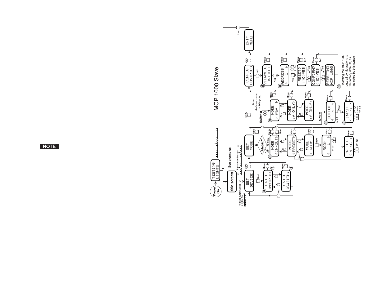
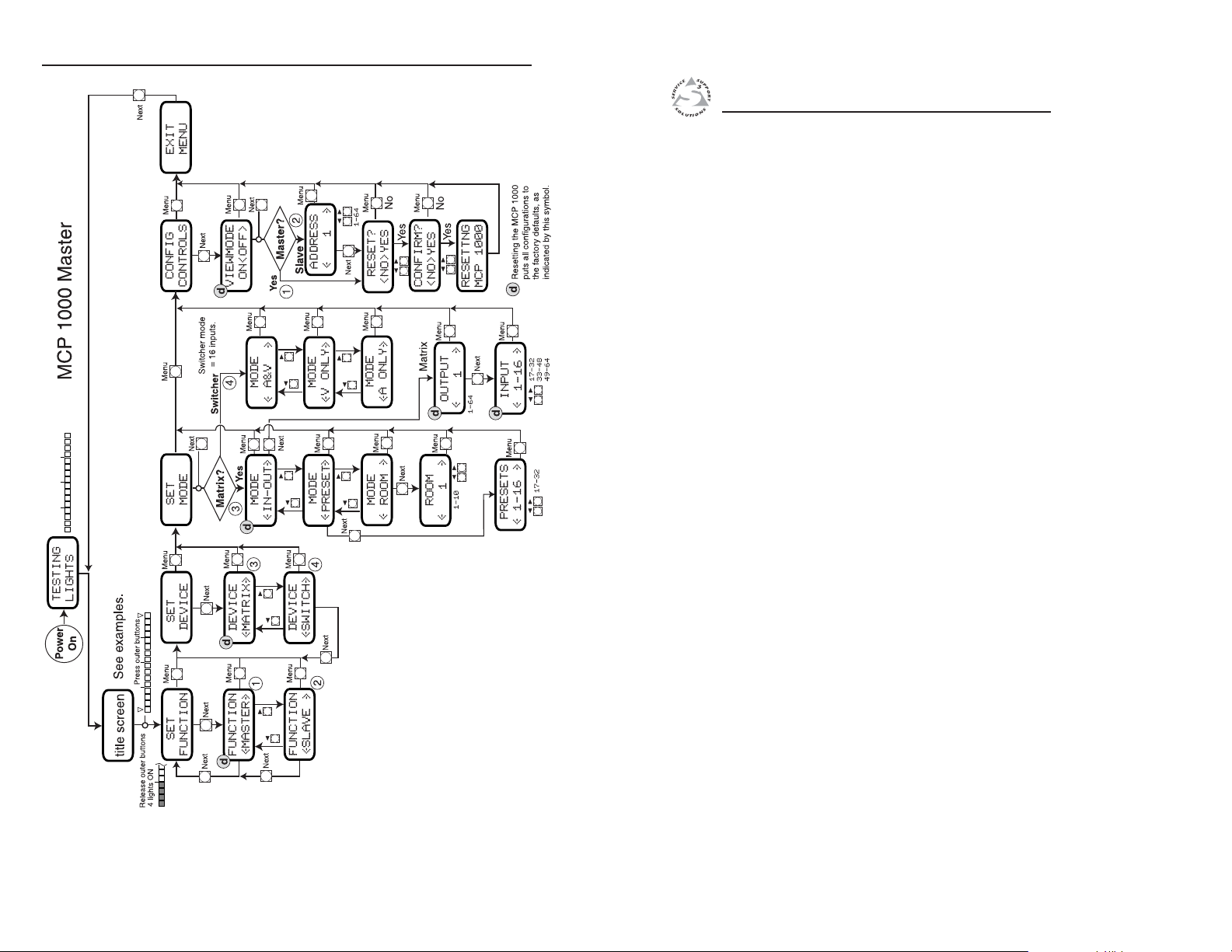
Setup fl ow charts
The MCP 1000 secondary mode fl ow chart is on page 3-11, and
the MCP 1000 primary mode fl ow chart is on page 3-12. On the
applicable fl ow chart, locate the mode in which you plan to
operate the MCP 1000.
Enter setup mode and, following the fl ow chart, press the
appropriate buttons to navigate through the menus and to make
the appropriate selections for your application. The LCD display
provides graphic prompts for the available choices. (See "LCD
display," earlier in this chapter.)
If necessary, you can reset the MCP 1000 to its default factory
settings. The reset command is available from the Confi g
Controls menu.
Each MCP 1000P and MCP 1000S must have a unique
address of 1 through 64. Secondary units are polled
periodically by either the MCP 1000P or by the primary
BME in a Matrix 3200/6400 system. Duplicate addresses
can cause the MCPs to lock up.
If you turned view mode on, when you exit setup mode the
LCD window displays a title screen that indicates the selected
operation mode.
3-10
MCP 1000 • Operation
MCP 1000 secondary mode fl ow chart
MCP 1000 • Operation
3-11
Page 18
Operation, cont’d
MCP 1000 Remote Control Panel
Appendix A
A
3-12
Specifi cations, Part Numbers,
and Accessories
Specifi cations
Included Parts
Cables
MCP 1000 primary mode flow chart
MCP 1000 • Operation
Page 19

Specifi cations, Part Numbers, and Accessories
Specifi cations
Control/remote — control panel
Serial control ports ....................... 1 host 9-pin female D connector
1 switcher 9-pin male D connector
Baud rate and protocol ............... 9600 baud, 8 data bits, 1 stop bit, no parity
Serial control pin confi gurations . 2 = TX, 3 = RX, 5 = GND
Extron remote key pad control ... (2) 5 mm, 5-pole captive screw connectors
Program control ............................. Extron’s Simple Instruction Set (SIS
General
Power
MCP 1000P ........................ 100 VAC to 240 VAC, 50/60 Hz, 15 watts,
internal, autoswitchable
MCP 1000S ......................... Supplied by the MCP 1000P or the matrix
switcher
Temperature/humidity ................ Storage: -40 to +158 °F (-40 to +70 °C) /
10% to 90%, noncondensing
Operating: +32 to +122 °F (0 to +50 °C) /
10% to 90%, noncondensing
Rack mount .................................... Yes, with included brackets. Also under-
furniture mountable or shelf-mountable
with included brackets.
Enclosure type .............................. Metal
Enclosure dimensions .................. 1.75" H x 17.5" W x 5.0" D
(1U high, full rack wide)
4.4 cm H x 44.5 cm W x 12.7 cm D
(Depth excludes connectors and knobs.
Width excludes rack ears.)
Product weight
MCP 1000P ........................ 3.0 lbs (1.4 kg)
MCP 1000S ......................... 2.5 lbs (1.1 kg)
Shipping weight
MCP 1000P ........................ 7 lbs (4 kg)
MCP 1000S ......................... 6 lbs (3 kg)
Vibration ........................................ ISTA 1A in carton (International Safe
Transit Association)
Listings............................................ UL, CUL
Certifi cations .................................. CE, FCC Class A
MTBF ............................................... 30,000 hours
Warranty ........................................ 3 years parts and labor
™
All nominal levels are at ±10%.
Specifi cations are subject to change without notice.
Included Parts
These items are included in each order for an MCP 1000:
Included parts Part numbers
)
MCP 1000P (primary unit) 60-298-01
MCP 1000S (secondary unit) 60-298-02
Red button caps (8) 70-111-01
Green button caps (8) 70-111-02
Yellow button caps (8) 70-111-03
Blue button caps (8) 70-111-04
Assorted button caps (8) 70-111-05
MBD 149 rack mounting kit 70-077-03
5-pole, 5 mm captive screw connector 10-163-13
MCP 1000 User’s Manual
Button Label Generator program 29-044-01
Cables
Plenum comm-link cable Part number
Cut lengths:
CTLP plenum 50' (15.2 m) long 26-461-01
CTLP plenum 100' (30.4 m) long 26-461-02
CTLP plenum 200' (61 m) long 26-461-03
CTLP plenum 400' (122 m) long 26-461-04
Bulk spools:
500' (152.4 m) 22-119-02
1000' (304.8 m) 22-119-03
A-2 A-3
MCP 1000 • Specifi cations, Part Numbers, and Accessories
MCP 1000 • Specifi cations, Part Numbers, and Accessories
Page 20

Specifi cations, Part Numbers, Accessories, cont’d
A-4 A-5
MCP 1000 • Specifi cations, Part Numbers, and Accessories
MCP 1000 • Specifi cations, Part Numbers, and Accessories
Page 21

Specifi cations, Part Numbers, Accessories, cont’d
A-6
MCP 1000 • Specifi cations, Part Numbers, and Accessories
 Loading...