

Page 1
Setup Guide
Matrix Switchers
CrossPoint 450 Plus Series
CrossPoint Ultra Series
MAV Plus Series
Matrix Switchers
68-521-50 Rev. C
10 19
Page 2

Safety Instructions
Safety Instructions • English
WARNING: This symbol, , when used on the product, is
intended to alert the user of the presence of uninsulated
dangerous voltage within the product’s enclosure that may
present a risk of electric shock.
ATTENTION: This symbol, , when used on the product, is
intended to alert the user of important operating and
maintenance (servicing) instructions in the literature provided
with the equipment.
For information on safety guidelines, regulatory compliances, EMI/EMF
compatibility, accessibility, and related topics, see the Extron Safety and
Regulatory Compliance Guide, part number 68-290-01, on the Extron
website, www.extron.com.
Sicherheitsanweisungen • Deutsch
WARNUNG: Dieses Symbol auf dem Produkt soll den
Benutzer darauf aufmerksam machen, dass im Inneren
des Gehäuses dieses Produktes gefährliche Spannungen
herrschen, die nicht isoliert sind und die einen elektrischen
Schlag verursachen können.
VORSICHT: Dieses Symbol auf dem Produkt soll dem
Benutzer in der im Lieferumfang enthaltenen Dokumentation
besonders wichtige Hinweise zur Bedienung und Wartung
(Instandhaltung) geben.
Weitere Informationen über die Sicherheitsrichtlinien,
Produkthandhabung, EMI/EMF-Kompatibilität, Zugänglichkeit und
verwandte Themen finden Sie in den Extron-Richtlinien für Sicherheit
und Handhabung (Artikelnummer 68-290-01) auf der Extron-Website,
www.extron.com.
Instrucciones de seguridad • Español
ADVERTENCIA: Este símbolo, , cuando se utiliza en el producto,
avisa al usuario de la presencia de voltaje peligroso sin aislar
dentro del producto, lo que puede representar un riesgo de
descarga eléctrica.
ATENCIÓN: Este símbolo, , cuando se utiliza en el producto,
avisa al usuario de la presencia de importantes instrucciones
de uso y mantenimiento recogidas en la documentación
proporcionada con el equipo.
Para obtener información sobre directrices de seguridad, cumplimiento
de normativas, compatibilidad electromagnética, accesibilidad y
temas relacionados, consulte la Guía de cumplimiento de normativas y
seguridad de Extron, referencia 68-290-01, en el sitio Web de Extron,
www.extron.com.
Instructions de sécurité • Français
AVERTISSEMENT: Ce pictogramme, , lorsqu’il est utilisé
sur le produit, signale à l’utilisateur la présence à l’intérieur
du boîtier du produit d’une tension électrique dangereuse
susceptible de provoquer un choc électrique.
ATTENTION: Ce pictogramme, , lorsqu’il est utilisé sur le
produit, signale à l’utilisateur des instructions d’utilisation
ou de maintenance importantes qui se trouvent dans la
documentation fournie avec le matériel.
Pour en savoir plus sur les règles de sécurité, la conformité à la
réglementation, la compatibilité EMI/EMF, l’accessibilité, et autres sujets
connexes, lisez les informations de sécurité et de conformité Extron, réf.
68-290-01, sur le site Extron,
www.extron.com.
Istruzioni di sicurezza • Italiano
AVVERTENZA: Il simbolo, , se usato sul prodotto, serve
ad avvertire l'utente della presenza di tensione non isolata
pericolosa all'interno del contenitore del prodotto che può
costituire un rischio di scosse elettriche.
ATTENTZIONE: Il simbolo, , se usato sul prodotto, serve
ad avvertire l'utente della presenza di importanti istruzioni di
funzionamento e manutenzione nella documentazione fornita
con l'apparecchio.
Per informazioni su parametri di sicurezza, conformità alle normative,
compatibilità EMI/EMF, accessibilità e argomenti simili, fare riferimento
alla Guida alla conformità normativa e di sicurezza di Extron, cod.
articolo 68-290-01, sul sito web di Extron, www.extron.com.
Instrukcje bezpieczeństwa • Polska
OSTRZEŻENIE: Ten symbol, , gdy używany na produkt, ma
na celu poinformować użytkownika o obecności izolowanego i
niebezpiecznego napięcia wewnątrz obudowy produktu, który
może stanowić zagrożenie porażenia prądem elektrycznym.
UWAGI: Ten symbol, , gdy używany na produkt, jest
przeznaczony do ostrzegania użytkownika ważne operacyjne
oraz instrukcje konserwacji (obsługi) w literaturze, wyposażone
w sprzęt.
Informacji na temat wytycznych w sprawie bezpieczeństwa, regulacji
wzajemnej zgodności, zgodność EMI/EMF, dostępności i Tematy
pokrewne, zobacz Extron bezpieczeństwa i regulacyjnego zgodności
przewodnik, część numer 68-290-01, na stronie internetowej Extron,
www.extron.com.
Инструкция по технике
безопасности • Русский
ПРЕДУПРЕЖДЕНИЕ: Данный символ, , если указан
на продукте, предупреждает пользователя о
наличии неизолированного опасного напряжения
внутри корпуса продукта, которое может привести к
поражению электрическим током.
ВНИМАНИЕ: Данный символ, , если указан на
продукте, предупреждает пользователя о наличии
важных инструкций по эксплуатации и обслуживанию в
руководстве, прилагаемом к данному оборудованию.
Для получения информации о правилах техники
безопасности, соблюдении нормативных требований,
электромагнитной совместимости (ЭМП/ЭДС), возможности
доступа и других вопросах см. руководство по безопасности
и соблюдению нормативных требований Extron на сайте
Extron: www.extron.com, номер по каталогу - 68-290-01.
安全说明 • 简体中文
警告: 产品上的这个标志意在警告用户该产品机壳内有暴露的危险
电 压 ,有 触 电 危 险 。
注意: 产品上的这个标志意在提示用户设备随附的用户手册中有
重要的操作和维护(维修)说明。
关于我们产品的安全指南、遵循的规范、EMI/EMF 的兼容性、无障碍
使用的特性等相关内容,敬请访问 Extron 网站 www.extron.com,参见
Extron 安全规范指南,产品编号 68-290-01。
Page 3

安全記事 • 繁體中文
警告: 若產品上使用此符號,是為了提醒使用者,產品機殼內存在著
可能會導致觸電之風險的未絕緣危險電壓。
注意 若產品上使用此符號,是為了提醒使用者,設備隨附的用戶手冊
中有重要的操作和維護(維修)説明。
有關安全性指導方針、法規遵守、EMI/EMF 相容性、存取範圍和相關
主題的詳細資訊,請瀏覽 Extron 網站:www.extron.com,然後參閱
《Extron 安全性與法規遵守手冊》,準則編號 68-290-01。
安全上のご注意 • 日本語
警告:この記号 が製品上に表示されている場合は、筐体 内に絶
縁されて いない高 電圧が流 れ、感 電の危険 があることを示し
てい ます。
注意: この記号 が製品上に表示されている場合は、本 機の取扱
説明書に 記載されている重要な操 作と保守(整備)の 指示につい
てユーザーの 注意を喚 起するものです。
安全上のご注意、法規厳守、EMI/EMF適合性、その他の関連項目に
つ い て は、エ クスト ロン の ウェ ブサ イト
り 『 Extron Safety and Regulatory Compliance Guide』 (P/N 68-290-01)
をご覧 くださ い。
www.extron.comよ
안전 지침 • 한국어
경고: 이 기호 , 가 제품에 사용될 경우, 제품의 인클로저 내에 있는
접지되지 않은 위험한 전류로 인해 사용자가 감전될 위험이 있음을
경고합니다.
주의: 이 기호 , 가 제품에 사용될 경우, 장비와 함께 제공된
책자에 나와 있는 주요 운영 및 유지보수(정비) 지침을 경고합니다.
안전 가이드라인, 규제 준수, EMI/EMF 호환성, 접근성, 그리고 관련
항목에 대한 자세한 내용은 Extron 웹 사이트
Extron 안전 및 규제 준수 안내서, 68-290-01 조항을 참조하십시오.
(www.extron.com)의
NOTE: For more information on safety guidelines, regulatory compliances,
EMI/EMF compatibility, accessibility, and related topics, see the “Extron Safety and
Regulatory Compliance Guide” on the Extron website.
Copyright
© 2008-2019 Extron Electronics. All rights reserved. www.extron.com
Trademarks
All trademarks mentioned in this guide are the properties of their respective owners.
The following registered trademarks, registered service marks, and trademarks are the
property of RGB Systems, Inc. or Extron Electronics (see the current list of trademarks on
the
Terms of Use page at www.extron.com):
Registered Trademarks
EExtron, Cable Cubby, ControlScript, CrossPoint, DTP, eBUS, EDID Manager,
EDID Minder, FlatField, FlexOS, Glitch Free, GlobalConfigurator, Global Scripter,
GlobalViewer, Hideaway, HyperLane, HyperLane, IPIntercom, IPLink, KeyMinder,
LinkLicense, LockIt, MediaLink, MediaPort, NetPA, PlenumVault, PoleVault, PowerCage,
PURE3, Quantum, Show Me, SoundField, SpeedMount, SpeedSwitch, StudionStation,
SystemINTEGRATOR, TeamWork, TouchLink, V-Lock, VersaTools, VN-Matrix,
VideoLounge, VoiceLift, WallVault, WindoWall, XPA, XTP, XTPSystems, and ZipClip
(SM)
Registered Service Mark
: S3 Service Support Solutions
Trademarks(™
AAP, AFL (Accu-RATEFrameLock), ADSP(Advanced Digital Sync Processing),
Auto-Image, AVEdge,CableCover, CDRS(ClassDRippleSuppression), DDSP(Digital
Display Sync Processing), DMI (DynamicMotionInterpolation), DriverConfigurator,
DSPConfigurator, DSVP(Digital Sync Validation Processing), eLink, EQIP, EverLast,
FastBite, Flex55, FOX, FOXBOX, IP Intercom HelpDesk, MAAP, MicroDigital, OptiTorque, PendantConnect, ProDSP, QS-FPC(QuickSwitch Front Panel Controller), Room
Agent, Scope-Trigger, ShareLink, SIS, SimpleInstructionSet, Skew-Free, SpeedNav,
Triple-Action Switching, True4K, Vector™ 4K, WebShare, XTRA, and ZipCaddy
(®)
)
Page 4

Page 5

Contents
Introduction ................................ 1
About this Guide ........................... 1
About the Matrix Switchers ........... 1
Installation
Rear Panel ..................................... 3
Making connections and rear
Front Panel Configuration Port
Operation
Creating a Tie ................................ 9
Saving or Recalling a Preset ....... 10
Setting the Front Panel Locks
(Executive Modes) ..................... 11
Selecting Lock mode 2 or ....... 11
Selecting Lock mode 2 or ....... 12
Viewing and Adjusting the ............ 13
Audio Level
.................................. 3
panel settings ........................... 5
(Matrix Sizes up to 1616,
MAV Plus 32 A, and
MAV Plus 248 A) ....................... 8
................................... 9
toggling between mode 2
and mode 0
toggling between mode 2
and mode 1
Remote Control ........................ 14
Selected SIS Commands ............ 14
Establishing a network
(Ethernet) connection ............. 14
Connection timeouts ............... 15
Number of connections ........... 15
Verbose mode ......................... 15
Host-to-switcher instructions .. 15
Installing and Starting the Control
Program
Installing the program .............. 21
Starting the program ............... 22
Accessing the HTML Pages ........ 23
Loading the start-up page........... 23
CrossPoint / MAV Matrix Switchers> • Contents v
Page 6

CrossPoint / MAV Matrix Switchers> • Contentsvi
Page 7

Introduction
NOTES:
For mor
•
refer to the CrossPoint 450 Plus / CrossPoint Ultra /
MAV Plus User Guide, available on the Extron website
(www.extron.com).
In this manual, the term “Cr
•
“450 Plus” or “Ultra” is not specied refers to either the
CrossPoint 450 Plus or the CrossPoint Ultra.
About this Guide
This setup guide allows you to easily and quickly set up and
congure your matrix switcher. Step by step instructions show you
how to connect the hardware. The guide also shows you how to
perform basic operations and use both the front panel controls and
selected Simple Instruction Set (SIS) commands. This guide also
shows you how to load and start up the Windows
Switchers Control Program. Lastly, this guide shows you how to
connect to the built-in HTML pages, which you can use to operate
the switcher.
e information on any subject in this guide,
ossPoint”, when
®
-based Matrix
About the Matrix Switchers
The Extron matrix switchers covered in this manual distribute any
input to any combination of outputs. The switchers can route multiple
input/output combinations simultaneously. The switchers are
available in a variety of matrix sizes (the number of inputs and outputs).
The CrossPoint switchers are available in HV (RGBHV video) and
HVA (RGBHV video and audio) models.
The MAV Plus matrix switchers are available in the following models:
• HDA — HDTV/component video and audio
• HD — HDTV/component video only
• SVA — S-video and audio
• SV — S-video only
• AV — Composite video and audio
• AV RCA — Composite video and audio on RCA connectors
(128 size only)
• V — Composite video only
• A — Audio only
CrossPoint / MAV Matrix Switchers • Introduction 1
Page 8
NOTES:
Extr
Cr
Ultra-Wideband Matrix Switcher
l
System
In this
•
manual, the term “video model” refers to any
CrossPoint or MAV Plus switcher that switches video.
• In this manual, the term “audio model” refers to any
CrossPoint or MAV Plus switcher that switches audio.
4
8
2
7
1
12
6
4
11
3
16
10
8
15
2
9
7
20
1
14
12
6
19
13
4
11
24
5
18
16
3
10
23
17
8
15
2
7
1
6
4
11
5
3
10
8
15
2
9
7
14
1
12
6
19
13
4
11
5
18
3
16
10
23
17
8
15
2
9
22
7
20
14
1
6
5
10
9
14
13
18
17
22
21
26
25
30
29
INP U TS
RED
OUT P UT S
2
1
6
5
10
9
14
13
18
17
22
21
26
25
30
29
L
R
1
L
18
L
R
17
L
L
R
1
L
ANAHEIM, CA
18
L
R
4.0A MAX
17
L
50/60Hz
~
100-240V
27
21
12
19
13
26
11
24
18
31
25
16
23
17
30
15
28
22
29
20
27
21
19
32
26
INP U TS
24
31
25
23
30
BLUE SYNC
28
29
3
27
OUT P UT S
2
32
INP U TS
7
1
31
6
GREEN
4
11
5
3
10
8
OUT P UT S
15
2
9
14
1
12
6
19
13
4
11
5
18
3
10
17
8
15
9
22
7
20
14
27
21
12
19
13
26
11
24
31
18
25
16
23
17
30
15
28
22
29
20
27
21
19
32
INPU T S
26
24
31
25
23
R
30
8
L
28
R
7
29
L
27
R
6
L
R
32
24
R
L
5
L
R
OUTP U TS
31
23
R
L
4
L
R
22
R
L
3
R
L
8
R
L
21
R
L
2
R
7
R
L
20
L
R
6
R
R
L
19
24
L
R
L
5
R
R
L
23
L
R
4
R
L
22
L
R
3
R
L
21
L
R
2
R
20
L
R
19
L
R
28
9
22
20
14
27
21
12
19
32
13
26
24
18
31
25
16
23
17
30
28
22
29
20
27
21
32
26
INP U TS
24
31
25
V SYNC
30
4
28
8
7
29
6
5
4
3
3
12
8
OUT P UT S
2
32
INP U TS
7
1
H
12
6
4
H V
11
5
78
6
5
3
16
4
10
23
1
8
OUT P UT S
15
2
9
7
20
1
14
6
13
4
11
5
10
17
8
15
9
14
21
12
19
13
18
25
23
17
28
22
29
27
15
L
31
25
R
14
L
30
R
28
13
L
29
31
R
L
12
L
R
30
R
32
L
11
L
R
29
R
L
10
L
R
15
L
28
R
L
9
R
L
R
14
L
27
L
R
R
13
L
26
31
L
L
R
R
12
R
L
25
30
L
L
R
11
R
L
29
L
R
10
R
L
28
L
R
9
R
L
27
L
R
26
L
R
25
L
Ethernet
19
24
18
23
28
22
27
32
26
31
30
R
8
16
L
R
R
32
L
RESET
R
ACTLINK
R
16
L
ETHERNET
R
R
RS 232/422
32
L
REMOTE
R
on
osspoint 450 Plus 3232 HVA
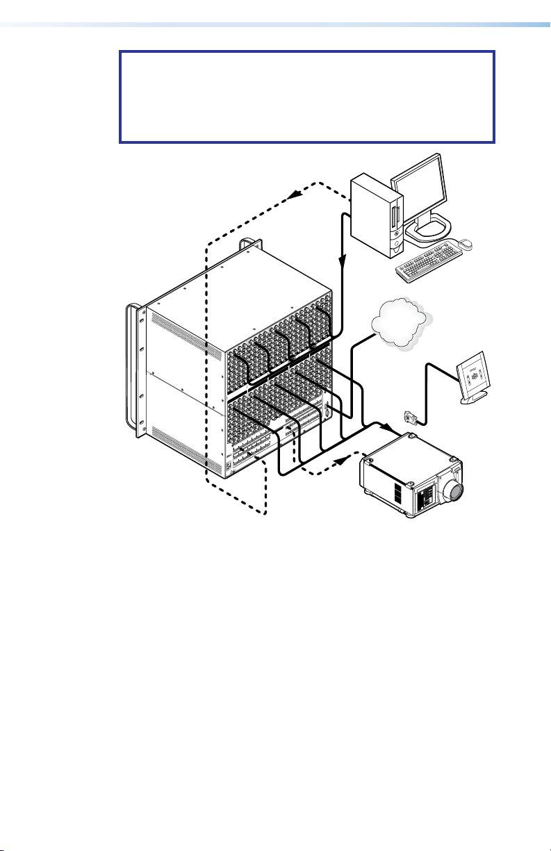
Figure 1. Typical Matrix Switcher Application
Computer
LAN
Contro
DLP Projector
2 CrossPoint / MAV Matrix Switchers • Introduction
Page 9
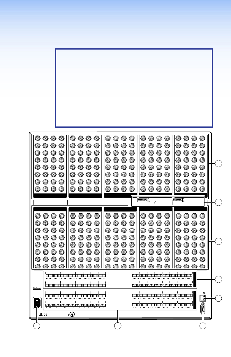
Installation
Rear Panel
NOTES:
•
The Cr
enclosures that range from 8U to 10U (see gure 2) to
support their different video format and matrix sizes.
•
The Cr
that range from 3U to 6U to support their different video
format and matrix sizes.
•
Smaller matrix sizes within a form factor have fewer
input and/or output connectors. The arrangement of
connectors and featur
factors is different from what is shown in gure 2.
ossPoint 450 Plus switchers are housed in
ossPoint Ultra switchers are housed in enclosures
es in switchers with different form
3
1
2
7
6
5
10
11
9
14
15
13
17
18
19
21
22
23
26
27
25
30
29
31
RED GREEN
OUTPUTS
1
3
2
7
6
5
10
11
9
14
15
13
17
18
19
21
22
23
26
27
25
30
29
31
L1R L2R L3R
L17R L18R L19R
ANAHEIM, CA
L1R
1.2A MAX
L9R L10R L11R
100-240V ~ 50/60Hz
L2R
L3R
4
8
12
16
20
24
28
32
3
1
2
7
6
5
10
11
9
14
15
13
17
18
19
21
22
23
26
27
25
30
29
31
INPUTSINPUTS
OUTPUTS OUTPUTS
4
8
12
16
20
24
28
32
L4R
L20R L21R L22R
L4R
L12R
®
3
1
2
7
6
5
10
11
9
14
15
13
17
19
18
21
23
22
26
27
25
30
29
31
L7R
L6R
L5R
L23R
L5R
L7R L8R
L6R
L13R
L14R L15R
LISTED
1T23
US
I.T.E.
4
8
12
16
20
24
28
32
3
1
2
7
6
5
10
11
9
14
15
13
17
18
19
21
22
23
26
27
25
30
29
31
BLUE SYNC
3
1
4
8
12
16
20
24
28
32
L8R
L24R
L16R
2
7
6
5
10
11
9
14
15
13
17
18
19
21
22
23
26
27
25
30
29
31
4
8
12
16
20
24
28
32
12345678 12345678
4
8
12
16
20
24
28
32
L10R L11R
L9R
L25R L26R L27R
L10R
L9R
L25R L26R L27R
3
1
2
7
6
5
10
11
9
14
15
13
17
18
19
21
22
23
26
27
25
30
29
31
Ω
Ω
H
HV
OUTPUTS OUTPUTS
1
3
2
7
6
5
10
11
9
14
15
13
17
18
19
21
22
23
26
27
25
30
29
31
L12R L13R
L28R L29R L30R
L12R L13R
L11R
L28R L29R
4
1
8
5
12
9
16
13
17
20
21
24
25
28
29
32
4
1
8
5
12
9
16
13
17
20
21
24
25
28
32
29
L14R L15R L16R
L31R
L15R L16R
L14R
L30R L31R
2
6
10
14
18
22
26
30
INPUTSINPUTSINPUTS
Ω
Ω
V SYNC
2
6
10
14
18
22
26
30
L32R
L32R
4
3
8
7
11
12
15
16
19
20
1
23
24
27
28
31
32
3
4
3
8
7
11
12
15
16
19
20
2
23
24
27
28
31
32
I
N
P
U
T
S
O
U
T
P
ETHERNET
U
T
S
REMOTE
4
RESET
ACT
9
LINK
RS 232/422
11
5
Figure 2. CrossPoint 450 Plus 3232 HVA Rear Panel
CrossPoint / MAV Matrix Switchers • Installation 3
8
Page 10
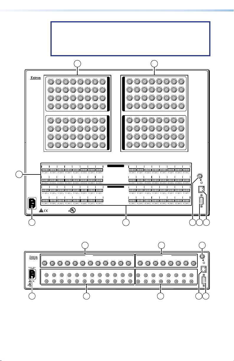
NOTE: The MAV Plus switchers are housed in enclosures that
range from 8U (see figure 3) to 2U (see figure 4) to support
their different video format and matrix sizes. The arrangement
of connectors and features in switchers with different form
factors is different from what is shown in figure 2.
1 2
1
O
U
T
P
Y
3
U
T
S
4
1
O
U
T
P
3
C
U
T
S
4
L 9 R
L 25 R L 26 R L 27 R
L 9 R
L 25 R L 26 R L 27 R
5
L 1 R
L17R
L 1 R
L 17 R
1
3
4
1
3
4
L 2 R L 3 R
L 18 R
L 2 R L 3 R
L 18 R
ANAHEIM, CA
4
100-240V 50/60Hz
1.2A MAX.
5
62
711
5
62
711
L 19 R
L 19 R
9
10
9
10
L 4 R L 5 R
L 20 R
L 21 R
L 4 R L 5 R
L 20 R L 21 R
®
13
17 21 25
15 19
20
16128
13
17 21 25
15 19
20
16128
L 6 R L 7 R L 8 R
L 22 R
L 6 R
L 22 R
LISTED
1T23
US
I.T.E.
26
221814
23
24
26
221814
27
23
24
L 23 R L 24 R
L 7 R
L 8 R
L 23 R L 24 R
29
30
I
N
P
27
31
U
T
S
3228
29
30
I
N
P
31
U
T
S
3228
INPUTS
OUTPUTS
11
5
62
711
5
62
711
L 10 R
L 10 R
L11R
L 11 R
13
17 21 25
9
10
15 19
20
16128
13
17 21 25
9
10
15 19
20
128
16
L12R
L13R
L 28 R
L 29 R
L 12 R
L 13 R
L 28 R
L 29 R
26
221814
27
23
24
26
221814
27
23
24
L 14 R L 15 R
L 30 R L 31 R
L 14 R L 15 R
L 31 R
L 30 R
29
30
31
3228
29
30
31
3228
L 16 R
L 32 R
L 16 R
L 32 R
SYNC
RESET
LAN
REMOTE
RS232/RS422
8 910
Figure 3. MAV Plus 3232 SVA Matrix Switcher
1 2
1
2
3
1
2
3
L
L
L
R
R
LISTED
1T23
®
US
I.T.E.
R
INPUTS
5
4
6
4
6
5
L
L
L
R
R
R
9
7
8
8
9
7
L
L
L
R
R
R
12
10
11
10
11
L
R
1 2
12
1
L
L
L
R
R
R
OUTPUTS
3
4
2
3
4
L
R
5
L
L
R
R
7
5
6
6
7
L
L
L
R
R
R
SYNC
8
RESET
LAN
8
L
R
REMOTE
RS232/RS422
11
6 7
Figure 4. MAV Plus 128 AV RCA Matrix Switcher
4 CrossPoint / MAV Matrix Switchers • Installation
8109
Page 11

Making connections and rear panel settings
1
2
1
2
1
2
1
2
1
2
WARNING: Turn the input and output devices off and
unplug their power cords.
AVERTISSEMENT: Éteindre tous les appareils d’entrée et de
sortie puis retirer les câbles d’alimentation.
NOTE: Video connectors are grouped by video
plane. Connect the input or output on each video
plane to the corresponding connector in the
correct group. Refer to the CrossPoint 450 Plus /
CrossPoint Ultra / MAV Plus Switcher Manual to
connect the various video formats to and from the
various models if you are not sure.
Video inputs — Connect RGBHV, RGBS, RGsB,
a
RsGsBs, component/HDTV video, S-video, or
composite video sources, as appropriate to the video
format and matrix size or your switcher model.
Video outputs — Connect RGBHV, RGBS, RGsB,
b
RsGsBs, component/HDTV video, S-video, or
composite video displays, as appropriate to the
video format and matrix size of your switcher
model's.
Sync termination switches (CrossPoint switchers) — Set
c
the switches as necessary to condition non-TTL sync levels
greater than 5 Vp-p. Sync termination enables the sync to be
properly passed from input to all selected outputs.
NOTES:
• CrossPoint 450 Plus switchers have Sync
termination switches for inputs 1 through 8.
• CrossPoint Ultra switchers have Sync termination
switches for inputs 1 through 4.
• The matrix switchers have two sets of sync
termination switches; one for horizontal or
combined sync and a second set for vertical sync.
510 ohms — The default position, suitable for most video.
75 ohms — Typically required only for an input with non-TTL
sync (greater than 5 V p-p).
NOTE: An input that produces an out of sync display,
a display that is rolling vertically and/or tearing
horizontally, could indicate a non-TTL sync input. If you
are not sure, check the specifications in the user manual
for the input device.
5CrossPoint / MAV Matrix Switchers • Installation
Page 12

Connections for balanced and unbalanced audio inputs
LR
(high impedance) (high impedance)
Tip
Slee
Slee
Tip
Balanced Output
LR
Tip
Tip
NO GR
NO GR
d
(most audio models) — Connect balanced or unbalanced
stereo audio inputs to these 5-pole captive screw
connectors.
ve
Tip
ve
Unbalanced Input
Ring
Sleeve (s)
Ring
Tip
Balanced Input
Figure 5. Audio Input Connector Wiring
Connections for balanced and unbalanced audio outputs
e
(most audio models) — Connect balanced or unbalanced
stereo audio output devices to these 5-pole captive screw
connectors.
OUND HERE.
Sleeve(s)
Tip
OUND HERE.
Unbalanced Output
Ring
Sleeve(s)
Ring
Tip
Figure 6. Audio output connector wiring
ATTENTION:
• For unbalanced audio, connect the sleeves to the
gr
ound contact. DO NOT connect the sleeves to the
negative (-) contact.
Pour l’audio asymétrique, connectez les manchons
•
au contact au sol.
aux contacts négatifs (–).
Ne PAS connecter les manchons
Connections for unbalanced audio inputs
f
(MAV Plus 126 AV RCA) — Connect unbalanced
audio inputs to each pair (left and right) of female
RCA connectors.
Connections for unbalanced audio outputs
g
(MAV Plus 126 AV RCA) — Connect unbalanced
audio output devices to each pair (left and right) of
female RCA connectors.
6 CrossPoint / MAV Matrix Switchers • Installation
stereo
stereo
Page 13

Remote port — If desired, connect a
9
—
Not used
—
Not used
RS-422RS-232
SYNC
51
96
h
control system or computer to the rear
panel Remote RS-232/RS-422 port
.
NOTE: Serial port defaults: RS-232, 9600 baud, no parity,
8-bit, 1 stop bit, no flow control.
Matrix Sizes:
All Models
Pin FunctionPin# PinFunction
1
—
TX
RX
—
Gnd
—
—
—
Not used
Transmit
Receive
Not used
Ground
Not used
Not used
Not used
2
3
4
5
6
7
8
LAN port — If desired, connect a network WAN or LAN hub, a
i
MAV Plus 248 / 328 A
Pin Function
—
Not used
TX–
Transmit –
RX–
Receive –
—
Not used
Gnd
Ground
—
Not used
RX+
Receive +
TX+
Transmit +
84 — 1616
Matrix Sizes:
2412 — 3232
2412 — 3232
Transmit +
TX+
Transmit –
TX–
Receive +
RX+
Receive –
RX–
Ground
Gnd
Not used
—
Not used
—
Not used
—
Not used
—
control system, or computer to the Ethernet RJ-45 port
Network connection — Wire as a patch (straight) cable.
Computer or control system connection — Wire the
interface cable as a crossover cable.
NOTE: The factory default IP address is
192.168.254.254.
.
External Sync (MAV Plus) — If desired, attach an external
j
sync timing device to the external sync connector.
BBG 6 A
BLACK BURST/COLOR BAR
/AUDIO GENERATOR
POWER
1 KHZ AUDIO
12V
+4dBu
0.5A MAX
1
LR
-10dBV
Extron
BBG 6 A
Black Burst Color Bar
Audio Generator
Te rminate cable
or connect to
another device.
1
NTSC
ON
1 2 3
BLACKBURST/
PAL
COLORBAR
432
BLACKBURST
OUT
Connect to
MAV Plus.
5
6
EXT
Figure 7. External Sync Connection
Power — Plug the switcher into a grounded AC source.
k
7CrossPoint / MAV Matrix Switchers • Installation
Page 14
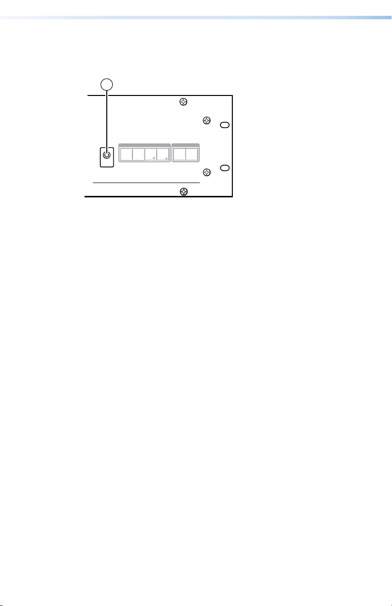
Front Panel Configuration Port
AUDIO
VIDEO
I/O
CONTROL
ENTERPRESET
VIEW
ESC
CONFIG
ULTRA-WIDEBAND MATRIX SWITCHER WITH ADSP
™
CROSSPOINT ULTRA SERIES
1
(Matrix Sizes up to 1616, MAV Plus 32 A, and
MAV Plus 248 A)
Figure 8. Front Panel Configuration Port
Configuration port — If desired, connect a control system or
a
computer to the front panel Configuration (RS-232) port. Use
an optional Extron 9-pin D to 2.5 mm mini jack TRS RS-232
cable.
8 CrossPoint / MAV Matrix Switchers • Installation
Page 15

Operation
when deselected.
The button lights to indicate the selection.
Amber
RGBHV/video
audio
Green
Red
indicates the
change.
NOTE: The video selection button is labeled “RGBHV” on
the CrossPoint switchers and “Video” on the MAV Plus
switchers. The two labels are used interchangeably in this
guide.
Creating a Tie
1. Press and release the Esc button to clear any input button,
output button, or control button indicators that may be lit.
2. Press and release the Video button, Audio button, or both to
select or deselect video, audio, or both, as desired.
Green when selected.
Off when deselected.
NOTE: Audio or video can be broken away (tied by itself)
3. Press and release the desired input button.
I / O
RGBHV AUDIO
Red when selected.
Off
by selecting only the Video button or only the Audio
button.
4. Press and release the desired output button(s).
5. Press and release the Enter button. All button indicators turn
off.
5
indicates
indicates RGBHV/video only tie.
indicates audio only tie.
3 4
and
8
CrossPoint / MAV Matrix Switchers • Operation 9
tie.
ENTER
Green
need to confirm the
Page 16

Saving or Recalling a Preset
.
Recall a
.
The button blinks red to indicate that
to indicate the need to
activate the save or recall.
1. Save a preset — Press and hold the Preset button until it
flashes.
Recall a preset — Press and release the
Preset button.
Save a
preset
preset
Press and hold.
PRESET
2 seconds
Preset button blinks
Press and release.
PRESET
Preset button lights
• All input and output buttons with
assigned presets light red.
• The configuration data at assigned
preset locations will be overwritten.
PRESET
PRESET
1 2 3 4 5 6
17 18 19 20 21 22
2. Press and release the desired input or output button.
this preset is selected to save or recall.
The Enter button blinks
ENTER
1
3. Press and release the Enter button.
red
10 CrossPoint / MAV Matrix Switchers • Operation
Page 17

Setting the Front Panel Locks (Executive Modes)
Press and hold simultaneously.
Release the buttons.
The matrix switcher has three levels of front panel security lock
that limit the operation of the switcher from the front panel. The
three levels are:
Lock mode 0 — The front panel is completely unlocked.
Lock mode 1 — All changes are locked from the front panel
(except for setting Lock mode 2). Some functions can be viewed.
Lock mode 2 — Basic functions are unlocked. Advanced features
are locked and can be viewed only.
Basic features consist of:
•
Making ties
Saving and r
•
•
Setting input audio gain and attenuation
•
Changing Lock modes
Advanced
•
Setting video and audio output mutes
Setting audio output volume
•
NOTE: The switcher is shipped in Lock mode 2.
Selecting Lock mode 2 or toggling between
mode 2 and mode 0
ecalling presets
features consist of:
NOTES:
If the switcher is in Lock mode 0 or mode 1, this
•
pr
ocedure selects mode 2.
• If the switcher is in Lock mode 2, this procedure selects
mode 0 (unlocks the switcher).
Toggle the lock on and off by pressing and holding the
Enter
button, the Video button, and the Audio button for approximately 2
seconds.
I / O
ENTER
ENTER
The buttons blink twice.
VIDEO AUDIO
2 seconds
I / O
VIDEO AUDIO
11CrossPoint / MAV Matrix Switchers • Operation
Page 18

Selecting Lock mode 2 or toggling between
Press and hold
The b
.
Release the buttons.
Press and
Hold
mode 2 and mode 1
NOTES:
If the switcher is in Lock mode 0 or mode 1, this
•
pr
ocedure selects mode 2.
• If the switcher is in Lock mode 2, this procedure selects
mode 1.
Toggle the lock on and off by pressing and holding the
button and the
simultaneously.
VIDEO AUDIO
2 seconds
VIDEO AUDIO
uttons blink twice
Audio button for approximately 2 seconds.
I / O
I / O
Viewing and Adjusting the Audio Level
1. Press and hold the Audio button until it flashes.
2 seconds
AUDIO AUDIO
Audio button blinks.
2. Press an input or output button. Refer to the
CrossPoint 450 Plus / CrossPoint Ultra / MAV Plus Switcher
Manual, chapter 3, “Operation”, to read the displayed value.
3. Increase/decrease the level or volume by pressing the
View (
and
4. Press and release the Audio button to exit.
) buttons.
<
Video
Esc (
)
>
12 CrossPoint / MAV Matrix Switchers • Operation
Page 19

Viewing and Adjusting the Audio Level
1. Press the View button. Output buttons light for outputs that
have no ties established.
NOTES:
If the Audio button blinks, audio is br
•
(switched separately from video).
If an output button blinks, that output is muted. T
•
toggle mute on and off, press and hold the output
button for 2 seconds.
2. Press an input button. The buttons for all tied outputs light
(amber for video and audio, green for video only, and red for
audio only).
3. Pr
ess an output button. The buttons for the tied input and all
tied outputs light.
4. Press the
an unlit state.
View button. All input and output buttons return to
oken away
o
13CrossPoint / MAV Matrix Switchers • Operation
Page 20

Remote Control
• Selected SIS Commands
Installing and Starting the Contr
•
• Accessing the HTML Pages
Selected SIS Commands
The switchers have Simple Instruction Set commands that you can
use for operation and conguration. You can run these commands
from a PC connected to either of the serial ports of the switcher
or the Ethernet port. See
connection information.
Establishing a network (Ethernet) connection
Establish a network connection as follows:
Open a TCP socket to port 23 using the switcher IP addr
1.
NOTE: The factory default IP address is 192.168.254.254.
The switcher responds with a copyright message including the
date, the name of the product, firmware version, part number,
and the current date and time.
ol Program
on page 7 and a on page 8, for
h, i
ess.
NOTES:
• If the switcher is not password-protected, the device
is now ready to accept SIS commands.
• If the switcher is password-protected, a password
prompt appears.
•
The factory configur
on this device have been set to the device serial
number. In the event of a complete system reset,
the passwords convert to the default, which is no
password.
2. If the switcher is password protected, enter the appropriate
password.
If the password is accepted, the switcher responds with
User or Login Administrator.
If the password is not accepted, the Password prompt
reappears.
CrossPoint / MAV Matrix Switchers • Remote Control14
ed passwords for all accounts
Login
Page 21

Connection timeouts
The Ethernet link times out and disconnects after a designated
period of time of no communications. By default, this timeout value
is set to ve minutes but the value can be changed. See the Set
Connection Timeout command on page 20.
NOTE: Extron recommends leaving the default timeout at ve
minutes and periodically issuing the Query (Q) command to
keep the connection active or disconnecting the socket and
reopening the connection when necessary.
Number of connections
A switcher can have up to 200 simultaneous TCP connections,
including all HTTP sockets and Telnet connections. When
the connection limit is reached, the switcher accepts no new
connections until some have been closed. No error message or
indication is given that the connection limit has been reached.
To maximize performance of your switcher, the number of
connections should stay low and unnecessary open sockets
should be closed.
Verbose mode
Telnet connections to a switcher can be used to monitor for
changes that occur on the switcher, such as front panel operations
and SIS commands from other Telnet sockets or a serial port.
For a Telnet session to receive change notices from the switcher,
the Telnet session must be in verbose mode 3. See the Verbose
Mode command on page 20. In verbose mode 3, the Telnet
socket reports changes in messages that resemble SIS command
responses.
Host-to-switcher instructions
The switcher accepts SIS commands through either serial port. SIS
commands consist of one or more characters per command eld.
They do not require any special characters to begin or end the
command character sequence. Each switcher response to an SIS
command ends with a carriage return and a line feed (CR/LF =
which signals the end of the response character string. A string is
one or more characters.
NOTE: The table that begins on the next page is a partial
list of SIS commands. For a complete listing, see the
CrossPoint 450 Plus / CrossPoint Ultra / MAV Plus Switcher
User Guide, chapter 4, “Programmer’s Guide”.
]
),
15CrossPoint / MAV Matrix Switchers • Remote Control
Page 22

Aditional information
Response
(switcher to host)
.
X@
.
.
X@
X@
is tied to output
is tied to output
video and audio to output
X!
X!
X!
Tie input 1 video and audio to output 3.
Audio breakaway.
Tie input 10 RGB to output 4.
Audio breakaway.
Tie input 7 video to output 5.
Audio breakaway.
Tie input 24 audio to output 4.
RGBHV input
Video input
]
]
Vid
X!•
In
X@•
]
Vid
•
In07
•
Out05
]
Aud
X!•
In
X@•
]
Aud
•
In24
•
Out04
X!]
X!]
]
All] Tie input
All
•
X!•
In
In01
•
X@•
Out03
RGB
X!•
In
X@•
]
RGB
•
In10
•
Out04
.
X@
is tied to output
X!
Audio input
X!]
! Out
& Out
% Out
X@
X@
X@
*
*
10*4&
X!
X!
RGBHV only
,
, video only
X@
X@
7*5%
(host to switcher)
*
1*3!
X!
, video and audio
X@
to output
to output
X!
to output
• Commands can be entered back-to-back in a string, with no spaces. For example: 1*1!02*02&003*003%4*24$.
• The matrix switchers support 1-, 2-, and 3-digit numeric entries (1*1!, 02*02&, or 003*003%).
• The & tie command for RGB and the % tie command for video can be used interchangeably.
• The & read tie command for RGB and the % read tie command for video can be used interchangeably.
Example:
Command SIS command
16 CrossPoint / MAV Matrix Switchers • Remote Control
NOTES:
Create and view ties
Tie input
X!
Example (see 3rd NOTE bullet, above):
Tie input
Example (see 3rd NOTE bullet, above):
Tie input
$ Out
X@
*
&
%
24*04$
X!
X@
X@
, audio only
X@
to output
X!
Example:
Tie input
Read RGB output tie
Read video output tie
$
X@
– (maximum number of outputs for your model)
– (maximum number of inputs for your model) (00 = untied)
00
01
X@ = Output number
Read audio output tie
KEY: X! = Input number
Page 23

RGB (video on).
RGB (video off).
X@
X@
Mute output
Unmute output
1 = mute on, 0 = mute off.
Aditional information
]
*1
X@
Response
(switcher to host)
Mute all RGB outputs.
]
*0
]
X@
Vmt1
X#]
audio (audio on).
audio (audio off).
X@
X@
response is the mute status of an output,
X$
Unmute all RGB outputs.
Mute output
Unmute output
1 = mute on, 0 = mute off.
Mute all audio outputs.
Unmute all audio outputs.
Each
]
n
X$
]
]
Vmt0
*1
X@
]
*0
X@
X#]
]
Amt1
]
Amt0
, ...
2
X$
,
1
= audio mute
2
]
Output 2, 3, and 5 audio is muted. All other
starting from output 1.
n = the maximum number of outputs for this
model.
outputs are unmuted.
= on (muted)
= video mute
1
1
Mut02202000000000000000000000000000
*1B Vmt
*0B Vmt
B
X@
X@
(host to switcher)
Command SIS command
Video and audio mute commands
X@
RGB or video mute
RGB or video unmute
Read RGB or video mute
*1Z Amt
1*B
0*B
X@
Global RGB or video mute
Global RGB or video unmute
Audio mute
*0Z Amt
Z
1*Z
X@
Audio unmute
0*Z
X@
Global audio mute
Global audio unmute
Read audio mute
} X$
VM
E
View output mutes
}
VM
E
CrossPoint 450 Plus 3232 HVA
Example:
– (maximum number of outputs for your model)
= off (unmuted)
= no mutes
01
0
0
X# = Mute
X$ = Video/audio mute:
NOTE: The Mut portion of the response appears only when the switcher is in Verbose mode 3. See the Verbose mode command on page XX.
KEY: X@ = Output number
17CrossPoint / MAV Matrix Switchers • Remote Control
Page 24

Set output 1 volume to a value of 50 (79% of max
volume, 14 dB of attenuation).
Aditional information
Increase volume by 1 step.
Decrease volume by 1 step.
[0 dB])
64
Command character is a comma.
Save current ties as preset 9.
Command character is a period.
Recall preset 5, which becomes the current
conguration.
]
X%]
•Vol
X@
Response
(switcher to host)
(host to switcher)
Command SIS command
Out01•Vol50
V Out
X%
*
1*50v
X@
Example:
Set the audio volume to a specic value
Audio output volume
]
X%]
X%]
•Vol
•Vol
X@
X@
Out01•Vol51
X%]
+V Out
-V Out
V
1+V
X@
X@
X@
Example:
Increment volume
Read output volume
Decrement volume
Save and recall presets
]
X^]
Spr09
. Rpr
,
9
X^
]
Rpr05
.
5
(1 dB/step except for 0-to-1, which is 22 dB) (default =
64
– (maximum number of outputs for your model)
–
01
0
X^]
, Spr
X^
X% = Volume
• If you try to recall a preset that is not saved, the matrix switcher responds with the error code E11.
• The following characters are invalid in preset names: + - , ` @ = [ ] { } ‘ “ ; : | \ and ?.
Example:
Example:
Recall a global preset
NOTES:
Save current conguration as a global preset
KEY: X@ = Output number
= current conguration)
00
(
32
–
00
X^ = Preset number
18 CrossPoint / MAV Matrix Switchers • Remote Control
Page 25

Enable Lock mode 1.
]
Exe1
Enable Lock mode 2.
]
Exe2
Aditional information
Response
(switcher to host)
Enable Lock mode 0.
]
Exe0
X&]
is the audio matrix size
is the video matrix size.
X(
X(
X
X
X*
X*
A
V
X(]
X
]
The factory-installed controller rmware version is
1.23 (sample value only).
X*
•A
X(
X
X*
V
V32X16•A32X16
X1)]
X1!]
]
1.23
(host to switcher)
NOTE: See Setting the front panel locks (Executive modes) on page 19 for more information on the Lock modes.
Lock (executive) modes
Command SIS command
2X
0X
1X
Lock all front panel functions
X
Lock advanced front panel functions
Unlock all front panel functions
View lock status
Information requests
I
I
MAV Plus 3216 HDA
Example:
Information request
N
Q
Q
2
, or
1
X* = Inputs Total number of inputs for this switcher
Example:
Request part number
Query controller rmware version
KEY: X& = Lock mode 0,
X( = Outputs Total number of outputs for this switcher
X1) = Part number 68-nnnn-nn
X1! = Firmware version number to second decimal place (x.xx)
19CrossPoint / MAV Matrix Switchers • Installation
Page 26

Aditional information
X1#]
X1#]
Ipi
}
CI
} X1#]
CI
EX1#
E
Ips
}
CS
} X1#]
CS
EX1#
E
Response
(switcher to host)
(host to switcher)
X1#]
Ipg
}
CG
} X1#]
CG
EX1#
E
X1$]
Idh
}
DH
} X1$]
DH
EX1$
E
X1%]
Vrb
}
CV
} X1%]
CV
EX1%
E
X1^]
Pti0*
}
TC
} X1^]
X1^
0*
0TC
E
E
X1^]
Pti1*
}
TC
} X1^]
X1^
1*
1TC
E
E
= 300 seconds = 5 minutes)
30
(default is
65000
= on
1
=off,
= clear/none (default for Telnet connection)
= verbose mode (default for RS-232/RS-422 connection)
= tagged responses for queries
= verbose mode and tagged for queries
0
0
1
(= 10 seconds) -
2
3
1
Set IP address
Read IP address
Set subnet mask
Read subnet mask
Set gateway IP address
Read gateway IP address
Set DHCP on or off
Read DHCP on/off status
Set verbose mode
Read verbose mode
Congure current port timeout
Command SIS command
IP setup
20 CrossPoint / MAV Matrix Switchers • Remote Control
Read current port timeout
X1$ = DHCP
Congure global IP port timeout
Read global IP port timeout
KEY: X1# = IP address ###.###.###.###
X1% = Verbose mode
X1^ = Port timeout interval
Page 27

Installing and Starting the Control Program
33
33333333
You can also operate the switcher via the Windows®-based Matrix
Switchers Control Program. This program is available on the Extron
website, www.extron.com. Run this program on a PC connected
to either of the switcher’s serial ports or the Ethernet port. See
on page 7 and a on page 8, for connection information.
i
NOTE: For details on operating the program, refer to the
CrossPoint 450 Plus / CrossPoint Ultra / MAV Plus Switcher
User Guide, chapter 5, “Matrix Software”.
Installing the program
1. Go to www.extron.com and hover the cursor over the
22222222
22
Download tab (
appears (
2
). The Find Software & Downloads link
1
).
1111111111
h
,
2. Click the Software (3) link. The main download page opens.
Click the M filtering letter (
3.
downloads nearest the program.
4. Click
Download for the Matrix Switchers Control Program (
) to jump to the page of
4
1111111111
5. Follow the on-screen instructions. The installation program
creates a C:\Program Files\Extron\Matrix_Switchers
directory and an “Extron Electronics\Matrix Switchers” group
folder. It installs the following four programs:
• MATRIX Switcher+ Control Program
• MATRIX Switcher+ Help
• Uninstall MATRIX Switcher
• Check for Matrix Updates
).
21CrossPoint / MAV Matrix Switchers • Remote Control
Page 28

Starting the program
1. Click Start > Programs > Extron Electronics > Matrix
Switchers > MATRIX Switcher + Control Pgm.
The Comm Port Selection window appears.
2. Choose the comm (serial) port that is connected to the
switcher or
NOTE: For a comm port, check the baud rate displayed
IP [LAN].
in the comm port selection window. If you need to
change the baud rate, click the Baud button and doubleclick the desired baud rate.
OK.
Click
3.
If you selected a serial port in step 2, the Matrix Switchers
Control Program is ready for operation.
4.
If you selected IP [LAN] in step 2
appears.
a. Examine the Matrix IP Address field, which displays the last
Matrix IP address entered.
If necessary, enter the correct IP address in the field.
NOTE: 192.168.254.254 is the factory-specied default
value for this eld.
22 CrossPoint / MAV Matrix Switchers • Remote Control
, the IP Connection window
Page 29

b. If the switcher is password protected, enter the appropriate
administrator or user password in the Password field.
NOTE: The factory configured passwords for all
accounts on this device have been set to the device
serial number. In the event of a complete system reset,
the passwords convert to the default, which is no
password.
c. Click
Connect. The Matrix Switchers Control Program is
ready for operation
Accessing the HTML Pages
Another way to operate the switcher is via its factory-installed
HTML pages, which are always available and cannot be erased or
overwritten. The switcher HTML pages are accessible through its
LAN port, connected via a LAN or WAN, using a web browser such
as Microsoft Internet Explorer. See
information.
Loading the start-up page
NOTES:
•
If your Ether
unstable, try turning off the proxy server in your Web
browser. In Microsoft Internet Explorer, click
Internet Options > Connections > LAN Settings,
>
uncheck the
OK.
• For details on operating the switcher via HTML pages,
refer to the CrossPoint 450 Plus / CrossPoint Ultra / MAV
Plus Switcher User Guide, chapter 6, “HTML Operation”.
1. Start the web browser program.
Click in the
2.
3. Enter the Matrix IP address in the Address field of the browser.
NOTE: 192.168.254.254 is the factory-specied default
value for this eld.
net connection to the matrix switcher is
Use a proxy server... box, and then click
Address field of the browser.
on page 8, for connection
a
Tools
23CrossPoint / MAV Matrix Switchers • Remote Control
Page 30

4. Press the keyboard <Enter> key. The switcher checks to see if
it is password protected.
NOTE: The factory configured passwords for all accounts
on this device have been set to the device serial number.
In the event of a complete system reset, the passwords
convert to the default, which is no password.
If the switcher is not password protected, it checks and
downloads the HTML start-up page. The switcher is ready for
operation via HTML remote control.
If the switcher is password protected, the switcher
downloads the
Enter Network Password page.
NOTE: A User name entry is not required.
Enter the appropriate administrator or user password in the
Password field and click OK.
5. The switcher downloads the HTML start-up page. The
switcher is ready for operation via HTML remote control.
24 CrossPoint / MAV Matrix Switchers • Remote Control
Page 31

Extron Warranty
Extron Electronics warrants this product against defects in materials and workmanship
for a period of three years from the date of purchase. In the event of malfunction during
the warranty period attributable directly to faulty workmanship and/or materials, Extron
Electronics will, at its option, repair or replace said products or components, to whatever
extent it shall deem necessary to restore said product to proper operating condition,
provided that it is returned within the warranty period, with proof of purchase and
description of malfunction to:
USA, Canada, South America,
and Central America:
Extron Electronics
1230 South Lewis Street
Anaheim, CA 92805
U.S.A.
Europe:
Extron Europe
Hanzeboulevard 10
3825 PH Amersfoort
The Netherlands
Africa:
Extron South Africa
South Tower
160 Jan Smuts Avenue
Rosebank 2196, South Africa
This Limited Warranty does not apply if the fault has been caused by misuse, improper
handling care, electrical or mechanical abuse, abnormal operating conditions, or if
modifications were made to the product that were not authorized by Extron.
NOTE: If a product is defective, please call Extron and ask for an application engineer
to receive an RA (return authorization) number. This will begin the repair process.
USA:
714.491.1500 or 800.633-9876
Asia: 65.6383.4400
Asia:
Extron Asia Pte Ltd
135 Joo Seng Road,
#04-01
PM Industrial Bldg.
Singapore 368363
Singapore
China:
Extron China
686 Ronghua Road
Songjiang District
Shanghai 201611
China
Eur
Japan
Japan:
Extron Electronics, Japan
Kyodo Building, 16 Ichibancho
Chiyoda-ku, Tokyo 102-0082
Japan
Middle East:
Extron Middle East
Dubai Airport Free Zone
F13, PO Box 293666
United Arab Emirates, Dubai
ope: 31.33.453.4040
: 81.3.3511.7655
Units must be returned insured, with shipping charges prepaid. If not insured, you assume
the risk of loss or damage during shipment. Returned units must include the serial number
and a description of the problem, as well as the name of the person to contact in case
there are any questions.
Extron Electronics makes no further warranties either expressed or implied with respect to
the product and its quality, performance, merchantability, or fitness for any particular use.
In no event will Extron Electronics be liable for direct, indirect, or consequential damages
resulting from any defect in this product even if Extron Electronics has been advised of
such damage.
Please note that laws vary from state to state and country to country, and that some
provisions of this warranty may not apply to you.
Page 32

Worldwide Headquarters: Extron USA West, 1025 E. Ball Road, Anaheim, CA 92805, 800.633.9876
 Loading...