

Page 1
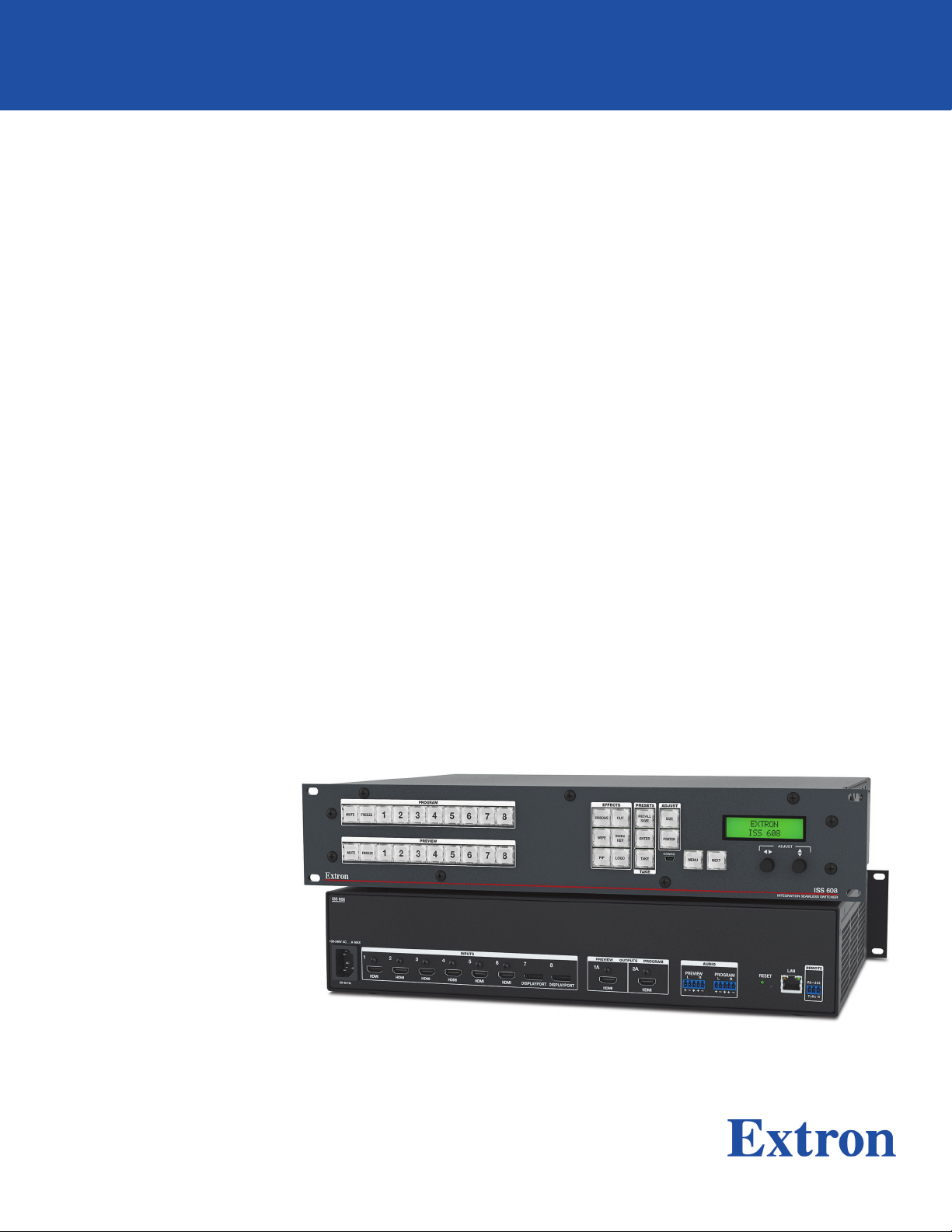
ISS 608
True Seamless 4K/60 HDMI and DisplayPort Switcher
User Guide
Seamless Switchers
68-2994-01 Rev. B
09 20
Page 2

Safety Instructions
Safety Instructions • English
WARNING: This symbol, , when used on the product, is intended to
alert the user of the presence of uninsulated dangerous voltage within
the product’s enclosure that may present a risk of electric shock.
ATTENTION: This symbol, , when used on the product, is intended
to alert the user of important operating and maintenance (servicing)
instructions in the literature provided with the equipment.
For information on safety guidelines, regulatory compliances, EMI/EMF
compatibility, accessibility, and related topics, see the Extron Safety and
Regulatory Compliance Guide, part number 68-290-01, on the Extron website,
www.extron.com.
Sicherheitsanweisungen • Deutsch
WARUNG: Dieses Symbol auf demProdukt soll den Benutzer darauf
aufmerksam machen, dass im Inneren des Gehäuses dieses Produktes
gefährliche Spannungen herrschen, die nicht isoliert sind und die einen
elektrischen Schlag verursachen können.
VORSICHT: Dieses Symbol auf dem Produkt soll dem Benutzer in
der im Lieferumfang enthaltenen Dokumentation besonders wichtige
Hinweise zur Bedienung und Wartung (Instandhaltung) geben.
Weitere Informationen über die Sicherheitsrichtlinien, Produkthandhabung,
EMI/EMF-Kompatibilität, Zugänglichkeit und verwandte Themen finden Sie in den
Extron-Richtlinien für Sicherheit und Handhabung (Artikelnummer
68-290-01) auf der Extron-Website, www.extron.com.
Instrucciones de seguridad • Español
ADVERTENCIA: Este símbolo, , cuando se utiliza en el producto, avisa
al usuario de la presencia de voltaje peligroso sin aislar dentro del
producto, lo que puede representar un riesgo de descarga eléctrica.
ATENCIÓN: Este símbolo, , cuando se utiliza en el producto,
avisa al usuario de la presencia de importantes instrucciones de
uso y mantenimiento estas estan incluidas en la documentación
proporcionada con el equipo.
Para obtener información sobre directrices de seguridad, cumplimiento
de normativas, compatibilidad electromagnética, accesibilidad y temas
relacionados, consulte la Guía de cumplimiento de normativas y seguridad de
Extron, referencia 68-290-01, en el sitio Web de Extron, www.extron.com.
Instructions de sécurité • Français
AVERTISSEMENT : Ce pictogramme, , lorsqu’il est utilisé sur le
produit, signale à l’utilisateur la présence à l’intérieur du boîtier du
produit d’une tension électrique dangereuse susceptible de provoquer
un choc électrique.
ATTENTION : Ce pictogramme, , lorsqu’il est utilisé sur le produit,
signale à l’utilisateur des instructions d’utilisation ou de maintenance
importantes qui se trouvent dans la documentation fournie avec
l’équipement.
Pour en savoir plus sur les règles de sécurité, la conformité à la réglementation,
la compatibilité EMI/EMF, l’accessibilité, et autres sujets connexes, lisez les
informations de sécurité et de conformité Extron, réf. 68-290-01, sur le site
Extron, www.extron.com.
Page 3
Copyright
© 2019-2020 Extron. All rights reserved. www.extron.com
Trademarks
All trademarks mentioned in this guide are the properties of their respective owners.
The following registered trademarks (®) and registered service marks (SM) are the property of RGBSystems, Inc. The trademarks (TM) are the property of
RGBSystems, Inc. or Extron (see the current list of trademarks on the Terms of Use page at www.extron.com):
Registered Trademarks (
®
)
Extron, Cable Cubby, ControlScript, CrossPoint, DTP, eBUS, EDID Manager, EDID Minder, eLink, Flat Field, FlexOS, Glitch Free, GlobalConfigurator,
GlobalScripter, GlobalViewer, Hideaway, HyperLane, IPIntercom, IPLink, KeyMinder, LinkLicense, LockIt, MediaLink, MediaPort, NAV,
NetPA, PlenumVault, PoleVault, PowerCage, PURE3, Quantum, ShareLink, Show Me, SoundField, SpeedMount, SpeedSwitch, StudioStation,
SystemINTEGRATOR, TeamWork, TouchLink, V-Lock, VideoLounge, VN-Matrix, VoiceLift, WallVault, WindoWall, XPA, XTP, XTPSystems, and ZipClip
Registered Service Mark
(SM)
: S3 Service Support Solutions
Trademarks (™
)
AAP, AFL (Accu-RATEFrameLock), ADSP(Advanced Digital Sync Processing), Auto-Image, AVEdge, CableCover, CDRS(ClassD Ripple
Suppression), Codec Connect, DDSP(Digital Display Sync Processing), DMI (DynamicMotionInterpolation), DriverConfigurator, DSPConfigurator,
DSVP(Digital Sync Validation Processing), EQIP, Everlast, FastBite, Flex55, FOX, FOXBOX, IP Intercom HelpDesk, MAAP, MicroDigital, Opti-Torque,
PendantConnect, ProDSP, QS-FPC(QuickSwitch Front Panel Controller), RoomAgent, Scope-Trigger, SIS, SimpleInstructionSet, Skew-Free,
SpeedNav, Triple-Action Switching, True4K, True8K, Vector™ 4K, WebShare, XTRA, and ZipCaddy
Page 4

FCC Class A Notice
This equipment has been tested and found to comply with the limits for a Class A digital
device, pursuant to part15 of the FCC rules. The ClassA limits provide reasonable
protection against harmful interference when the equipment is operated in a commercial
environment. This equipment generates, uses, and can radiate radio frequency energy and,
if not installed and used in accordance with the instruction manual, may cause harmful
interference to radio communications. Operation of this equipment in a residential area is
likely to cause interference. This interference must be corrected at the expense of the user.
NOTES:
• This unit was tested with shielded I/O cables on the peripheral devices. Shielded
• For more information on safety guidelines, regulatory compliances, EMI/EMF
cables must be used to ensure compliance with FCC emissions limits.
compatibility, accessibility, and related topics, see the Extron Safety and
Regulatory Compliance Guide on the Extron website.
Page 5
Conventions Used in this Guide
Notifications
The following notifications are used in this guide:
ATTENTION:
• Risk of property damage.
• Risque de dommages matériels.
NOTE: A note draws attention to important information.
TIP: A tip provides a suggestion to make working with the application easier.
Software Commands
Commands are written in the fonts shown here:
^AR Merge Scene,,0p1 scene 1,1 ^B 51 ^W^C.0
[01] R 0004 00300 00400 00800 00600 [02] 35 [17] [03]
E X! *X1&* X2)* X2#* X2! CE}
NOTE: For commands and examples of computer or device responses used in this
Computer responses and directory paths that do not have variables are written in the font
shown here:
Reply from 208.132.180.48: bytes=32 times=2ms TTL=32
C:\Program Files\Extron
Variables are written in slanted form as shown here:
ping xxx.xxx.xxx.xxx —t
SOH R Data STX Command ETB ETX
Selectable items, such as menu names, menu options, buttons, tabs, and field names are
written in the font shown here:
From the File menu, select New.
Click the OK button.
guide, the character “0” is the number zero and “O” is the capital letter “o.”
Specifications Availability
Product specifications are available on the Extron website, www.extron.com.
Extron Glossary of Terms
A glossary of terms is available at http://www.extron.com/technology/glossary.aspx.
Page 6

Page 7

Contents
Introduction ................................................1
About this Manual................................................ 1
About the Integration Seamless Switcher ............. 1
Features .............................................................. 2
Installation .................................................. 6
Mounting the ISS608 .......................................... 6
Rear Panel Overview ........................................... 6
Power Connection ........................................... 6
Video Input Connections .................................. 6
Output Connections ........................................ 7
Reset Button ................................................... 7
Control Connections ........................................ 9
Operation..................................................11
Front Panel Controls and Indicators ................... 11
Mute, Freeze, Input Selection,
and Effects Controls ..................................... 11
Picture Adjustment and
Menu System Controls ................................. 12
Front Panel Security Lockout
(Executive Modes) ........................................ 13
Front Panel Menu Operation .............................. 13
Menu Navigation ............................................ 13
Menu Overview ............................................. 14
Input Presets Menu........................................ 15
Picture Controls Menu ................................... 16
Input Configuration Menu .............................. 17
Output Configuration Menu............................ 18
Effect Configuration Menu.............................. 20
Background/Logo Configuration Menu .......... 23
Advanced Configuration Menu ....................... 25
View and Edit Communications
Settings Menu .............................................. 27
Exit Menu ...................................................... 28
Front Panel Button Operations........................... 29
Front Panel Button Shortcuts ......................... 29
Front Panel Button Colors .............................. 29
Selecting an Input .......................................... 30
Switching the Preview Output to
the Program Output ...................................... 30
Recalling a Layout Preset............................... 30
Configuring and Recalling a Logo Preset ....... 31
Adjusting the Size and Position
of the Program or Preview ............................ 32
Matrix Mode ...................................................... 33
Upstream Signal Switching and
Local Video Bus Switching ............................... 34
SIS Configuration and Control ...................35
Connections Options ......................................... 35
Rear Panel RS-232 Port ................................ 35
Front Panel Configuration USB Port ............... 35
Ethernet Link ................................................. 35
Default Address ............................................. 36
Symbols ........................................................ 36
Host-to-Switcher Communications .................... 36
Switcher-Initiated Messages .............................. 36
Switcher Error Responses ............................. 37
Using the Command and Response Tables ....... 38
Command and Response Tables ....................... 43
Configuration Software .............................58
Software/Firmware Installation ........................... 58
Connecting to PCS ............................................ 60
Device Discovery Panel .................................. 60
TCP/IP Panel ................................................. 61
Offline Device Preview .................................... 61
Software Overview ............................................. 62
Software Menu .............................................. 63
Device Menu.................................................. 65
viiTechnical Publications Standards and Styles • Contents
Page 8

Internal Web Page ..................................... 67
Accessing the Internal Web Page ...................... 67
Disabling Compatibility Mode ......................... 68
Web Page Panels .............................................. 68
Device Info Panel ........................................... 69
Device Status Panel ....................................... 69
Network Settings Panel ................................. 70
Inputs Panel................................................... 70
Outputs Panel ................................................ 71
RS-232 Panel ................................................ 71
Firmware Panel .............................................. 72
Roles and Permissions Panel ......................... 72
About the ISS608 ......................................... 73
Reference Information ............................... 74
Mounting the Switcher ....................................... 74
Tabletop Placement ....................................... 74
Rack Mounting .............................................. 74
Front Panel Menu Diagrams ............................. 76
Input Presets, Picture Controls, Input
Configuration, and Output Configuration ....... 76
Effect Configuration ....................................... 77
Background/Logo Configuration .................... 78
Advanced Configuration and
View Comm Settings .................................... 79
Technical Publications Standards and Styles • Contents viii
Page 9

Introduction
The topics in this section are:
• About this Manual
• About the Integration Seamless Switcher
• Features
About this Manual
This manual contains installation, configuration, and operating information for the Extron
ISS608 Integration Seamless Switcher.
About the Integration Seamless Switcher
The Extron ISS608 is an eight-input, scaling, video and audio seamless switcher for the
dynamic presentation of HDMI and DisplayPort content at resolutions up to 4K/60Hz.
With six HDMI 2.0 and two DisplayPort 1.2 inputs that support signals up to 4096x2160 at
60Hz with 4:4:4 color sampling, the ISS combines true seamless switching with advanced
Vector™ 4K scaling technology.
NOTE: The terms ISS, ISS608, scaler, and switcher refer to the ISS608.
The ISS provides multiple seamless transition effects, an independent preview output, and
intuitive front panel operation. Logo insertion, video keying, and Picture In Picture (PIP)
capabilities complement primary content, and audio de-embedding simplifies integration.
Matrix Mode (see page33) adds automatic, seamless transitions to matrix switchers
with HDMI outputs. In addition, RS-232 and Ethernet provide optimal control options.
These features and capabilities enable the ISS608 to deliver a true seamless digital signal
switching solution perfect for high-end, live presentation environments.
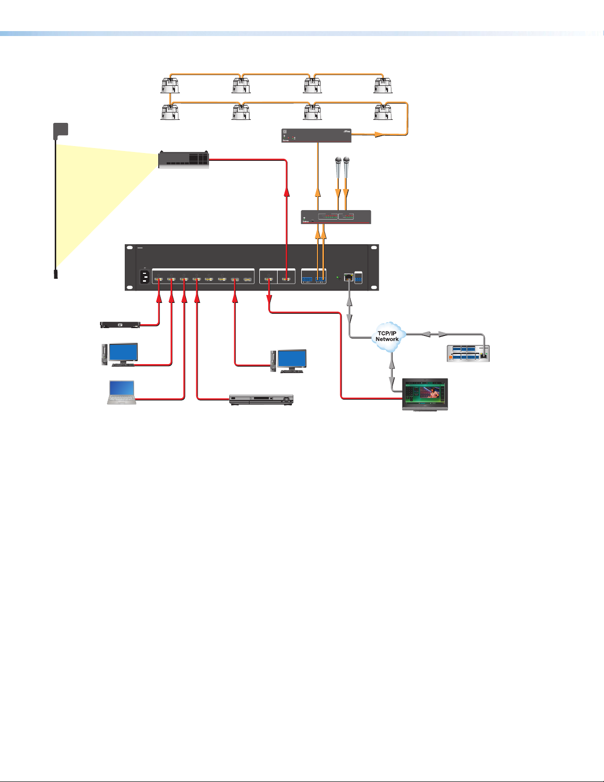
Figure1 on page2 shows a typical ISS608 application. The switcher accepts up to
eight video inputs of various resolutions, scales the video inputs, and outputs video and
audio.
The ISS 608 seamlessly switches between the program and preview inputs without a loss
of video or sync. The ISS offers a wide range of effects that eliminate distracting jumps,
glitches, and delays, as well as allows the user to choose transitions most appropriate for
the material. Effects include wipes with selectable direction and duration, a dissolve with
selectable duration, and a seamless cut. The audio transition can also be accompanied by
either a cut or a fade audio effect.
Each video input is individually configurable to support different video formats. The ISS
allows the various high-resolution and low-resolution video formats to be seamlessly
switched between for display in high profile, professional presentation spaces.
The ISS provides two separate outputs:
• Program output — The program output is the video seen by the audience.
• Preview output — The preview output allows the switcher operator to view the video
before it is transitioned to the program output for the audience to see.
ISS 608 Seamless Switcher • Introduction 1
Page 10
Extron
SF 26CT
Full-Range
Ceiling Speakers
4K Media Player
Computer
BYOD
ISS 608
100-240V --A MAX
50-60 Hz
HDMI
Projector
HDMI1HDMI2HDMI3HDMI
HDMI
Extron
XPA 20 01-70 V
Power Amplier
OVER
TEMP
LIMITER/PROTECT
SIGNAL
XPA 2001
Audio
Microphones
HDMI
Audio
Audio
INPUTS
OUTPUTS
CLIP
CLIP
SIGNAL
SIGNAL
1 2 3 4 5 6
CONFIG
Audio
1 2 3 4
DIGITAL MATRIX PROCESSOR
DMP 64
Extron
DMP 64
Digital Matrix
Processor
Extron
INPUTS
4
6 7
HDMI DISPLAYPORT
8
DISPLAYPORT
5
HDMI
1A
HDMI
OUTPUTSPREVIEW PROGRAM
2A
AUDIO
PREVIEW
PROGRAM
L R
HDMI
L R
LAN
RESET
HDMI
DisplayPort
Workstation PC
HDMIHDMI
DSS Receiver
ISS 608
REMOTE
4K/60 HDMI
RS-232
and DisplayPort
Tx Rx
G
Seamless Switcher
Ethernet
Ethernet
Ethernet
COM 1
COM 2
DIGITAL I/O
IPCP PRO 250
G
Tx Rx RTS CTS
G
Tx Rx
1 2 3 4 G
POWER
RELAYS
eBUS
IR/S
VOL
12V
1 2 C
V CG
1A MAX
+V+S-SG
S G
PWR OUT = 6W
LAN
Extron
TLP Pro 1720TG
17" Tabletop
TouchLink Pro
Touchpanel
Extron
IPCP Pro 250
IP Link Pro
Control Processor
Features
Figure 1. Typical ISS608 Integration Seamless Switcher Application
The ISS608 scales the input up or down to any of a wide variety of output resolutions
and rates. The scaler outputs the scaled video on two connectors, one HDMI program
connector and one HDMI preview connector.
The switcher features built-in test patterns to aid in display setup and evaluation.
The switcher is housed in a rack-mountable, 2U high, 17.4 inch wide, metal enclosure. The
ISS has an internal 100 VAC to 240 VAC, 50-60 Hz, 45 watts internal power supply that
provides worldwide power compatibility.
• Inputs: Six female HDMI type-A and two female DisplayPort connectors.
• Outputs: Two female HDMI type-A and two 3.5 mm 5-pole captive screw connectors.
• True seamless switching between eight digital inputs — Provides sophisticated
transition effects for presentations and live events.
• Multiple transition effects include wipes, dissolve, and cut — Offers a wide range
of effects that eliminate distracting jumps, glitches, and delays, as well as allows the
user to choose transitions most appropriate for the material. Effects include wipes with
selectable direction and duration, a dissolve with selectable duration, and a seamless
cut.
• Preview and Program outputs — Independent video buses for Preview and Program
outputs enable the operator to preview and adjust video prior to displaying on the main
display.
ISS 608 Seamless Switcher • Introduction 2
Page 11

• Advanced Extron Vector 4K scaling engine — The Vector 4K scaling engine is
specifically designed for critical-quality 4K imagery, with best-in-class image upscaling
and downscaling.
• Supports computer and video resolutions up to 4K/60 @ 4:4:4 — Supports
HDMI2.0 and DisplayPort 1.2 signals up to 4096x2160 at 60 Hz with 4:4:4 color
sampling.
• Supported HDMI 2.0 specification features include data rates up to 18 Gbps,
Deep Color, and HD lossless audio formats.
• HDCP 2.3 compliant — Ensures display of content-protected media and
interoperability with other HDCP-compliant devices.
• Matrix Mode — HDMI inputs 1 and 2 support Matrix Mode, which adds seamless
switching and transition effects to any matrix switcher with HDMI outputs.
• PIP - picture-in-picture — Allows any input to be displayed on-screen simultaneously
with another. The PIP window can be dynamically sized and positioned anywhere within
the output and is transitioned into or out of the output using the dissolve effect. Sixteen
PIP presets are also available.
• Video keying — Title information or other content from an input source can be keyed
over the Program image.
• Logo image keying and display — A logo graphic can be positioned and keyed over
live video. Logo graphics in BMP, JPG, PNG, or TIFF format may be uploaded to the
unit. Full screen images up to 4K resolution can also be displayed to eliminate loss of
video between presentations. Up to 16 logo images can be stored.
• Take button sends preview content to the audience using the selected effect
— Pressing the Take button on the front panel sends the preview content from the local
monitor to the main display device. The switch is performed with the selected effect,
providing a seamless transition between sources.
• Aspect ratio control — The aspect ratio of the video output can be controlled by
selecting a FILL mode that provides a full screen output or a FOLLOW mode, which
preserves the original aspect ratio of the input signal.
• Motion-adaptive deinterlacing for signals up to 1080i — Advanced deinterlacing
for all interlaced signals up to 1080i delivers optimized image quality.
• Automatic 3:2 and 2:2 pulldown detection — Advanced film mode processing
techniques that help maximize image quality for content sources originating from film.
• Auto-Image setup — Automatically optimizes the image by analyzing and adjusting
to the video input signal. This can save time and effort in setting up a newly connected
source, particularly in presentation environments where different guest presenter laptops
with various output resolutions will be connected.
• Auto Input Memory — When activated, the unit automatically stores size, position,
and picture settings based on the incoming signal. When the same signal is detected
again, these image settings are automatically recalled from memory.
• Input presets — Memory presets are available to store and recall image settings.
• Layout presets — Memory presets are available to store and recall user settings. This
provides a quick method to set up content preview in anticipation of transitioning it to
the Program output.
• Output mute — Allows independent muting for Preview and Program output signals.
• Output freeze — Provides independent freeze control of the program and preview
output signals. Frozen content can be switched to the Program output using any
transition effect.
ISS 608 Seamless Switcher • Introduction 3
Page 12

• User-selectable HDCP authorization — Allows each HDMI input to appear HDCP
compliant or non-HDCP compliant to the connected source, which is beneficial if the
source automatically encrypts all content when connected to an HDCP-compliant
device. Protected material is not passed in non-HDCP mode.
• HDCP Visual Confirmation provides a green signal when encrypted content
is sent to a non-compliant display — A green window with an alert message is
displayed when HDCP-encrypted content is transmitted to a non-HDCP compliant
display, providing immediate visual confirmation that protected content cannot be
viewed on the display.
• Key Minder continuously verifies HDCP compliance for quick, reliable
switching — Key Minder authenticates and maintains continuous HDCP encryption
between input and output devices to ensure quick and reliable switching in professional
AV environments, while enabling simultaneous distribution of a single source signal to
one or more displays.
• SpeedSwitch Technology delivers virtually instantaneous switching speeds for
HDCP-encrypted content.
• EDID Minder automatically manages EDID communication between connected
devices — EDID Minder ensures that all sources power up properly and reliably output
content for display.
• EDID capture mode — EDID information can be captured and stored from connected
program and preview display devices.
• Comprehensive picture controls for Preview and Program output buses — Fine
tune displayed content with picture controls for brightness, contrast, sizing, positioning,
and zoom.
• Internal video test patterns and pink noise generator for calibration and setup
— The ISS offers several video test patterns and audio pink noise to facilitate proper
system setup and calibration of display devices.
• Audio management — Embedded two-channel digital audio can be extracted from
any input and sent to the Preview and Program analog audio outputs. Multi-channel
audio formats can be passed to the Preview and Program HDMI outputs.
• Easy setup and commissioning with Extron PCS - Product Configuration
Software — Convenient configuration and preset design from a single easy-to-use
software application.
• Front panel controls with LCD display — Back-lit front panel buttons and an LCD
menu system with navigation controls ensure simplified operation in live presentation
environments and provide quick access to configuration settings.
• Ethernet monitoring and control — Enables control and proactive monitoring over a
LAN or WAN.
• Built-in web pages — Enables the use of a standard browser for device monitoring
and simple troubleshooting over an intuitive web interface.
• RS-232 control port — Supports the use of serial commands for integration into
a control system. Extron products use the SIS - Simple Instruction Set command
protocol, a set of basic ASCII commands that allow for quick and easy programming.
• Front panel USB configuration port — Enables easy configuration without having to
access the rear panel.
• Executive Mode lockout — Provides restriction to access of controls.
• Includes LockIt HDMI cable lacing brackets.
• Rack-mountable 2U, full rack width metal enclosure.
ISS 608 Seamless Switcher • Introduction 4
Page 13

• Internal Extron Everlast power supply — Provides worldwide power compatibility,
with high demonstrated reliability and low power consumption for reduced operating
cost.
• Extron Everlast Power Supply is covered by a 7-year parts and labor warranty.
ISS 608 Seamless Switcher • Introduction 5
Page 14
Installation
The topics covered in this section are:
• Mounting the ISS608
• Rear Panel Overview
Mounting the ISS608
The ISS608 is housed in a 2U high, full rack width metal enclosure that can sit on a table
with the provided rubber feet or be mounted using the attached rack mounts.
Select a suitable mounting location (see Mounting the Switcher on page75), then
choose an appropriate mounting option.
• Before connecting the ISS608, turn off all devices that are to be connected.
• Connect all external devices to the ISS before applying power.
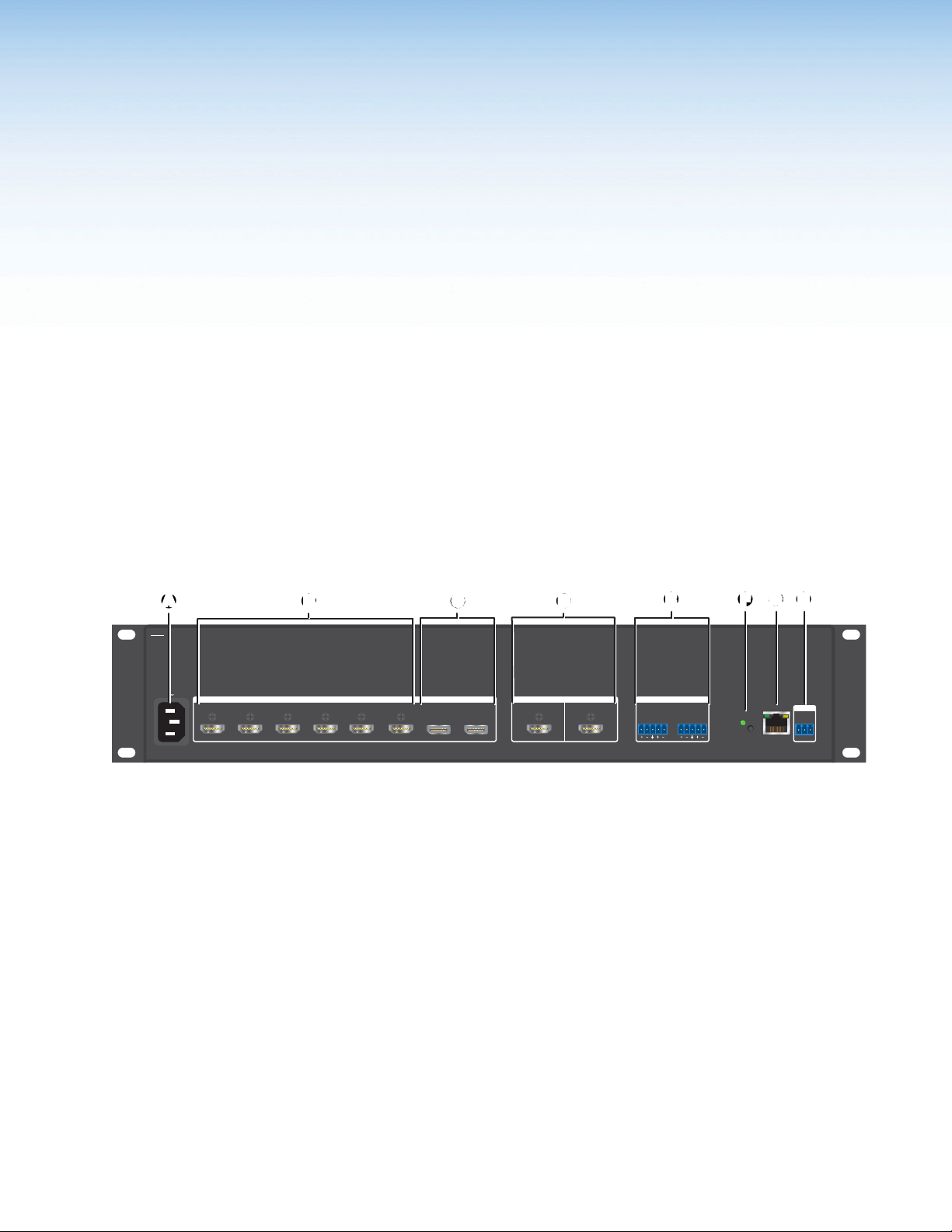
Rear Panel Overview
ISS 608
100-240V --A MAX
50-60 Hz
HDMI1HDMI2HDMI3HDMI
INPUTS
4
5
HDMI
A AC power connector
B HDMI input connectors 1 through 6
C DisplayPort input connectors 7 and 8
HDMI output connectors
D
Figure 2. ISS608 Rear Panel Connectors
Power Connection
AC power connector — Plug a standard IEC power cord into this connector to
A
connect the seamless switcher to a 100 to 240 VAC, 50 Hz or 60 Hz power source.
Video Input Connections
6 7
HDMI DISPLAYPORT
8
DISPLAYPORT
1A
HDMI
D
DCCBB
OUTPUTSPREVIEW PROGRAM
2A
HDMI
E
E
AUDIO
PREVIEW
PROGRAM
L R
L R
Analog audio outputs
E
Reset button and LED
F
LAN connector
G
Remote RS-232 connector
H
FFAAGG HH
LAN
RESET
REMOTE
RS-232
Tx Rx
G
HDMI input connectors 1 through 6 — Connect HDMI video to these inputs.
B
DisplayPort input connectors 7 and 8 — Connect DisplayPort video to these inputs.
C
ISS 608 Seamless Switcher • Installation 6
Page 15
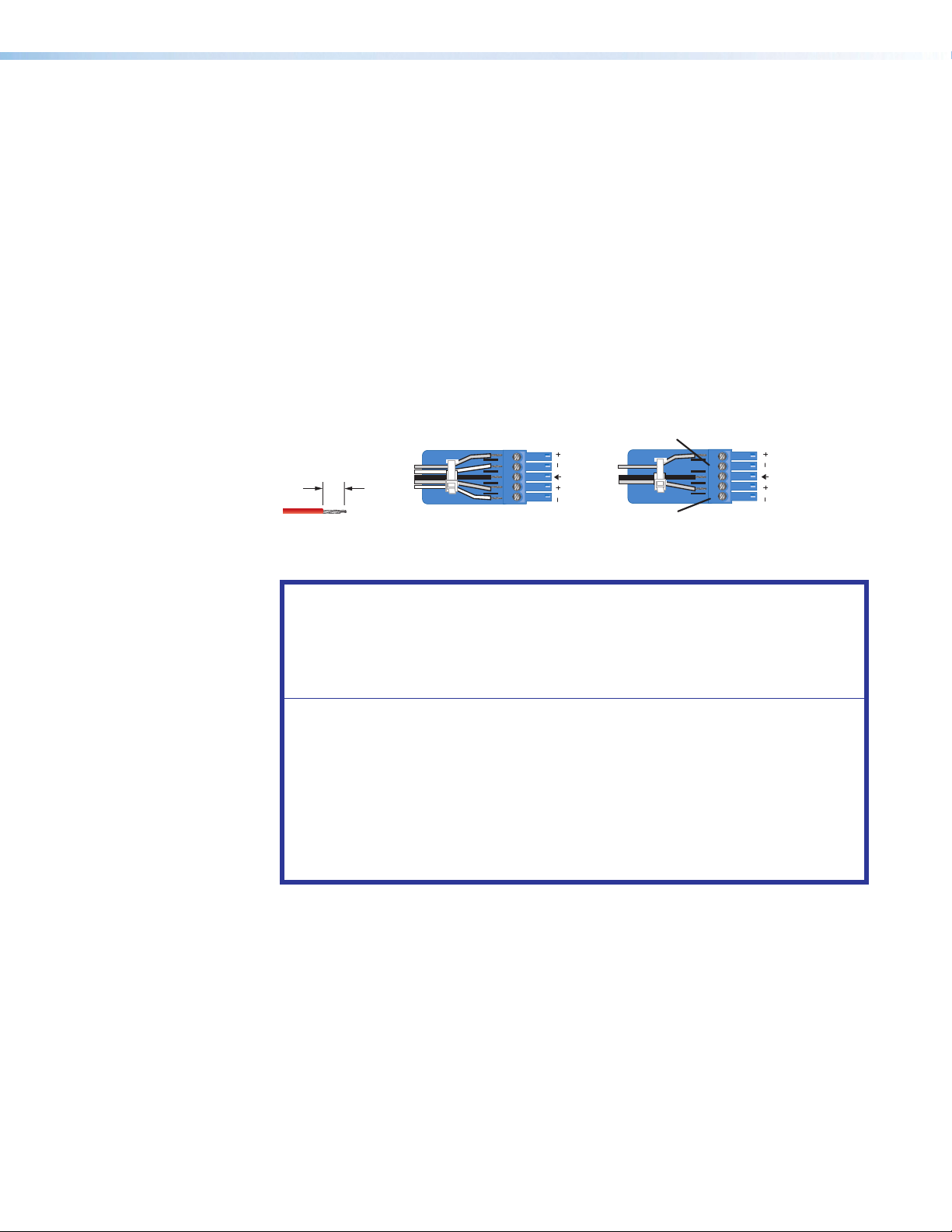
Output Connections
Balanced Audio Output
Tip
Ring
Tip
Ring
Sleeves
Unbalanced Audio Output
Tip
No Ground Here
No Ground Here
Tip
Sleeves
LR
LR
Do not tin the wires
3/16” Max
(5mm)
Video output connections
HDMI output connectors (see figure2 on page6) — Connect displays to the
D
Program and Preview HDMI output connectors.
• The Program connector (2A) outputs the video image for the program display or
projector.
• The Preview connector (1A) outputs the video image for the local display.
Audio output connections
Analog audio outputs — Connect audio devices, such as an audio amplifier or
E
powered speakers, to these 3.5 mm, 5-pole captive screw connectors. The connectors
output the selected unamplified, line level audio de-embedded from the HDMI and
DisplayPort inputs (see figure3 to properly wire an output connector). Use the supplied
tie-wrap to strap the audio cable to the extended tail of the connector.
Figure 3. Captive Screw Connector Wiring for Audio Output
Reset Button
ATTENTION:
• Connect the sleeve to the ground (Gnd) terminal. Connecting the sleeve to a
negative (-) terminal will damage the audio output circuits.
• Connectez le manchon à la borne de terre (Gnd). Connecter le manchon à une
borne négative (-) endommagera les circuits de la sortie audio.
• The length of the exposed wires in the stripping process is important. The ideal
length is 3/16 inches (5 mm). Any longer and the exposed wires may touch,
causing a short circuit between them. Any shorter and the wires can be easily
pulled out even if tightly fastened by the captive screws.
• La longueur des câbles exposés est importante lorsque l’on entreprend de
les dénuder. La longueur idéale est de 5 mm (3/16 inches). S’ils sont trop
longs, les câbles exposés pourraient se toucher et provoquer un courtcircuit. S’ils sont trop courts, ils peuvent être tirés facilement, même s’ils sont
correctement serrés par les borniers à vis.
By default, the de-embedded analog audio output follows the video switch, but it can
be split via SIS commands (see Audio follow on page49). Audio output can also be
muted via SIS commands (see Audio mute (digital and analog - persists beyond a
power cycle) on page49)
Reset button and LED — Initiates four levels of reset to the switcher. Use an Extron
F
Tweeker or small screwdriver to press and hold the button while the switcher is running
or while you power up the switcher for different reset levels.
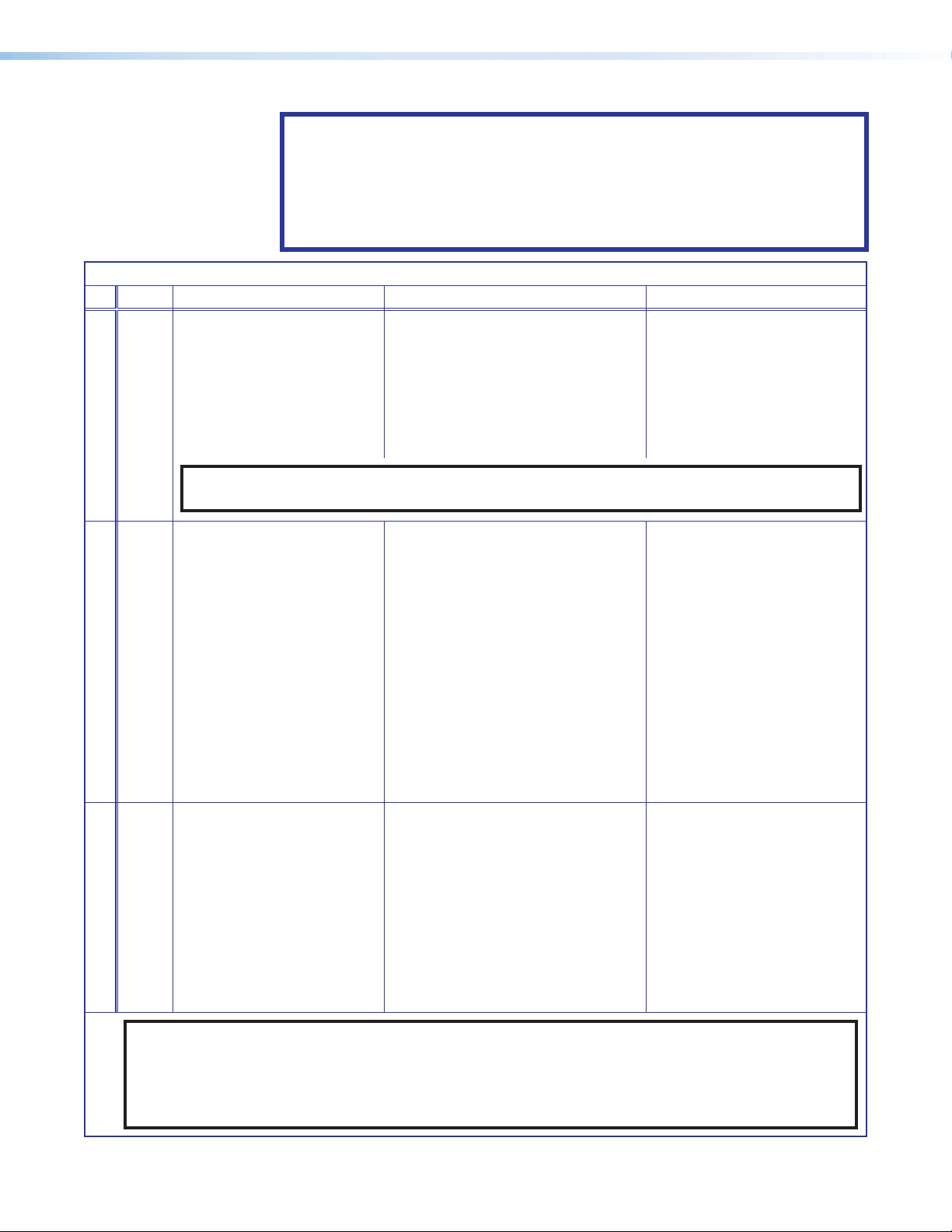
See the ISS608 Reset Modes table on page8 and figure4 on page9 for a
summary of the function of the reset modes and how to perform them.
ISS 608 Seamless Switcher • Installation 7
Page 16
ATTENTION:
• Review the reset modes carefully. Some reset modes delete all user loaded
content and revert the device to default configuration.
• Analysez minutieusement les différents modes de réinitialisation. Certains
modes de réinitialisation suppriment l’intégralité du contenu chargé de
l’utilisateur et remettent l’appareil au mode de configuration par défaut.
ISS608 Reset Modes
Mode Activation Result Purpose and Notes
1 Hold in the recessed rear
panel Reset button while
applying power to the unit.
The ISS608 reverts to the factory
default firmware for a single power
cycle.
Use mode 1 to revert to
the factory default firmware
for a single power cycle if
incompatibility issues arise
with user-loaded firmware.
All user files and settings are
maintained.
Use Factory Firmware
*4
most current firmware to the device.
Hold in the Reset button
until the Reset LED blinks
twice (once at 3 seconds,
again at 6 seconds). Then,
release and press the
Reset button again within 1
second*.
• Sets port mapping back to
factory default.
• Sets the IP address
back to factory default
(192.168.254.254).
• Sets the subnet mask address
back to the factory default
Mode 4 is used to set
IP address information using
ARP and the MAC address.
Resetting IP Settings
appears on a connected
display.
(255.255.255.0).
• Sets the gateway IP address to
the factory default (0.0.0.0).
NOTE: Do not operate with the default firmware loaded by a mode1 reset. Use it only to load the
Reset All IP Settings
• Turns DHCP off.
• The Reset LED on the rear panel
of the unit flashes four times in
succession.
*5
Hold in the Reset button
until the Reset LED blinks
three times (once at 3
seconds, again at 6 seconds,
again at 9 seconds). Then,
release and press the
Reset button again within 1
second*.
Reset to Factory Defaults
Performs a complete reset to factory
defaults (except the firmware).
• Does everything mode 4 does.
• Clears port configurations.
• Resets all IP options.
• Clears all user settings.
• Clears all files from the unit.
• The Reset LED on the rear panel
of the unit flashes four times in
succession.
Mode 5 is useful to start over
with default configuration and
uploading, and also to replace
events.
Resetting ISS 608 appears
on a connected display.
Mode 5 is equivalent to
SIS command ZQQQ (see
SIS command Resets on
page55).
NOTES:
• *For modes 4 and 5, nothing happens if the momentary press does not occur within 1 second.
• The factory configured passwords for all accounts on this device have been set to the device serial
number. In the event of a complete system reset, the passwords convert to the default, which is no
password (see Passwords on page57 to change a password).
ISS 608 Seamless Switcher • Installation 8
Page 17
Mode 1
Press and hold
the Reset button.
RESET RESET
Apply power
to the ISS 608.
Release Reset button.
Mode 4
Press and hold
for 6 seconds.
Mode 5
Press and hold
for 9 seconds.
Reset LED flashes twice.
RESET RESET
Reset LED flashes three
times.
RESET
RESET
Release, then immediately
press and release again.
Reset LED flashes, then goes off.
RESET
Release, then immediately
press and release again.
Reset LED flashes, then goes off.
RESET
Figure 4. Whole Switcher and Absolute Resets
Control Connections
Ethernet connection
LAN connector (see figure2 on page6) — Connect the seamless switcher to an
G
Ethernet LAN or WAN via this RJ-45 connector. Ethernet control allows the operator to
control the seamless switcher from a remote location. When connected to an Ethernet
LAN or WAN, the seamless switcher can be accessed and operated from a computer
running a standard Internet browser.
Ethernet connection indicators — The Link and Activity LEDs indicate the status of
the Ethernet connection.
• Link LED — Indicates the seamless switcher is properly connected to an Ethernet
LAN. This LED should light steadily.
• Activity LED — Indicates transmission of data packets on the RJ-45 connector.
This LED should flicker as the seamless switcher communicates.
Choosing a network cable
Ethernet links use Category (CAT) 3, 4, 5, 5e, or 6, unshielded twisted pair (UTP) or shielded
twisted pair (STP) cables, terminated with RJ-45 connectors. Ethernet cables are limited to
328 feet (100 m).
ATTENTION:
• Do not use standard telephone cables. Telephone cables do not support Ethernet
or Fast Ethernet. Do not stretch or bend cables. This can cause transmission
errors.
• Ne pas utiliser de câbles téléphone standard. Les câbles de téléphone ne sont pas
compatibles avec les liaisons Ethernet ou Fast Ethernet. Ne pas étirer ou plier les
câbles. Cela pourrait provoquer des erreurs de transmission.
The cable used depends on network speed. The ISS supports 10 Mbps (10Base-T) and
100 Mbps (100Base-T), half-duplex and full-duplex Ethernet connections.
• 10Base-T Ethernet requires at a minimum CAT 3 UTP or STP cable.
• 100Base-T Fast Ethernet requires at a minimum CAT 5 UTP or STP cable.
ISS 608 Seamless Switcher • Installation 9
Page 18
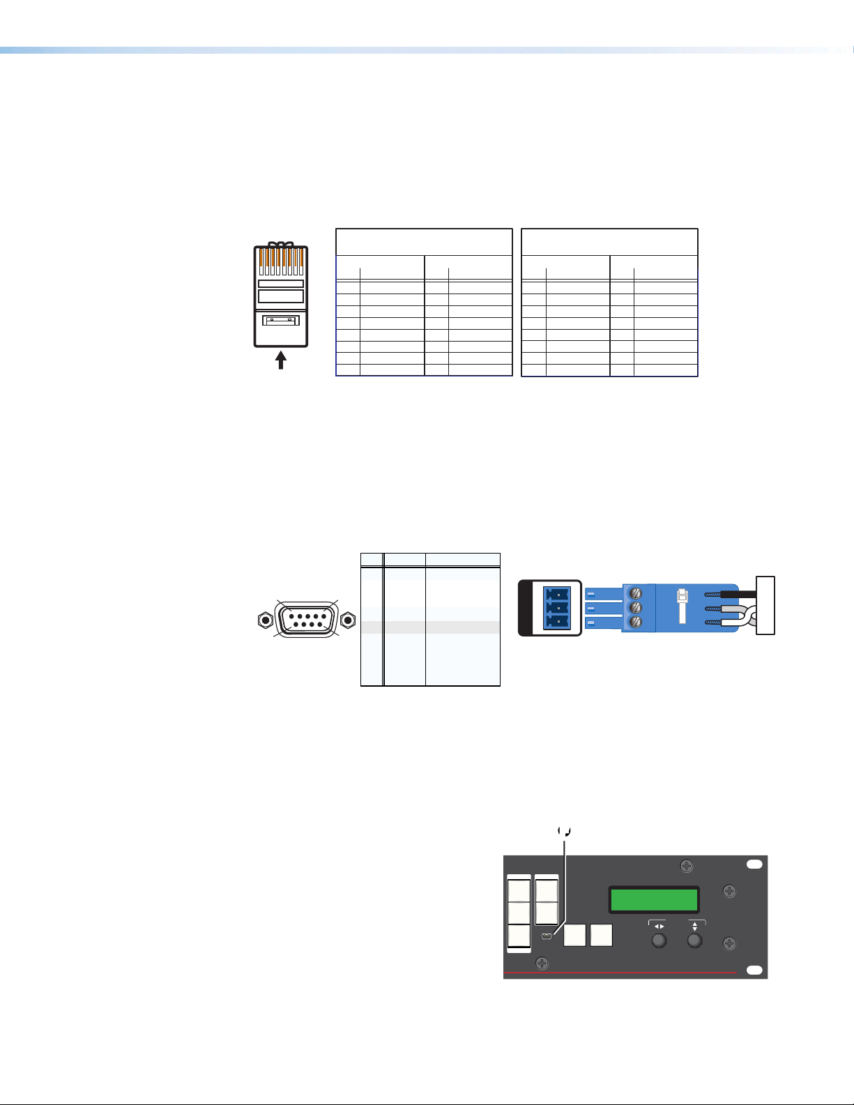
Wiring the network cable
12345678
RJ-45
Connector
Insert Twisted
Pair Wires
Pins:
A cable that is wired as TIA/EIA T568A at one
end and T568B at the other (Tx and Rx pairs
reversed) is a "crossover" cable.
A cable wired the same at both ends is called
a "straight-through" cable because no pin/pair
assignments are swapped.
T568B T568A T568B T568B
Straight-through Cable
(for connection to a switch, hub, or router)
End 1 End 2
Pin Wire Color Pin Wire Color
1 white-orange 1 white-orange
2 orange 2 orange
3 white-green 3 white-green
4 blue 4 blue
5 white-blue 5 white-blue
6 green 6 green
7 white-brown 7 white-brown
8 brown 8 brown
Crossover Cable
(for direct connection to a PC)
End 1 End 2
Pin Wire Color Pin Wire Color
1 white-orange 1 white-green
2 orange 2 green
3 white-green 3 white-orange
4 blue 4 blue
5 white-blue 5 white-blue
6 green 6 orange
7 white-brown 7 white-brown
8 brown 8 brown
RS-232 FunctionPin
REMOTE RS-232
The cable can be terminated as either a patch cable or a crossover cable (see figure5) and
must be properly terminated for the application:
• Patch (straight-through) cable — Connection of the ISS to an Ethernet hub, router,
or switch that also hosts a controlling computer.
• Crossover cable — Direct connection between the ISS and a controlling computer.
Figure 5. RJ-45 Connector Pinout Table
Serial port connection
Remote RS-232 port (see figure2 on page6) — Connect a host device, such
H
as a computer or touchpanel controller, to the rear panel bidirectional RS-232 port (see
figure6 for wiring). The default baud rate is 9600.
RS-232
51
9
Figure 6. Remote Port Pin Assignments and Wiring Diagram
See SIS Configuration and Control starting on page35 for definitions of the SIS
commands and Configuration Software starting on page59 to install and use the
control software.
Front panel configuration port
USB Configuration port (see figure7
F
or figure8 on page11)— This USB
mini-B port serves the same serial
communications function as the rear
panel Remote port, but is easier to
access than the rear port after the
switcher has been installed and cabled.
1
—
Tx
Rx
—
Gnd
—
—
—
—
Not used
Transmit data
Receive data
Not used
Signal ground
Not used
Not used
Not used
Not used
RS-232
REMOTE
G
Tx Rx
RxTx Gnd
2
3
4
5
6
6
7
8
9
FF
PRESETS ADJUST
RECALL
SIZE
SAVE
POSITION
ENTER
CONFIG
TAKE
TAKE
MENU NEXT
Figure 7. Front Panel Configuration
Port
ISS 608 Seamless Switcher • Installation 10
ADJUST
INTEGRATION SEAMLESS SWITCHER
ISS 608
Page 19
Operation
This topics in this section are:
• Front Panel Controls and Indicators
• Front Panel Menu Operation
• Front Panel Button Operations
• Matrix Mode
• Upstream Signal Switching and Local Video Bus Switching
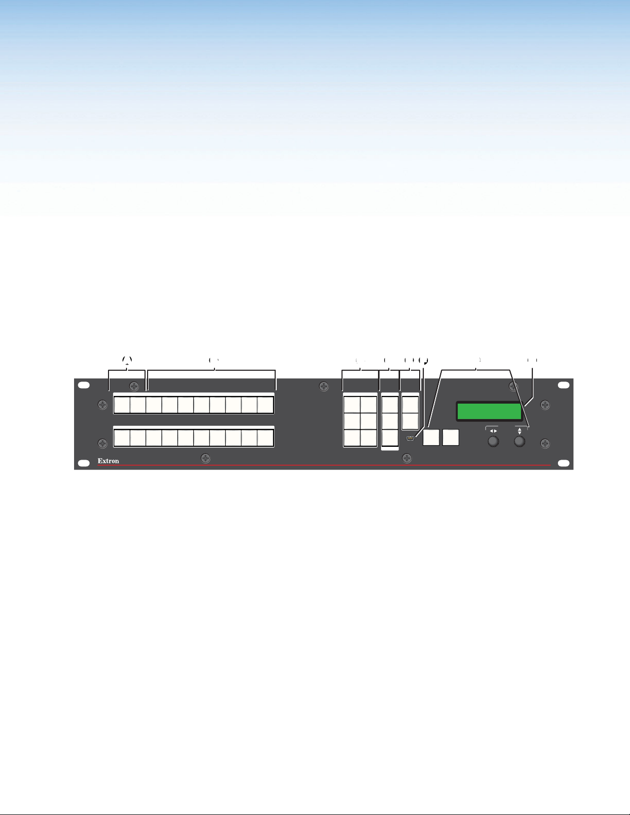
Front Panel Controls and Indicators
All of the switcher controls and indicators, with the exception of the Reset button, are on the
front panel (see figure8). The 16 x 2 character LCD window indicates the switcher status,
menu selections, the data rate, and the status of additional system features.
AA
FFDD G
EE
GCCBB
HH
MUTE FREEZE
MUTE FREEZE
PROGRAM EFFECTS PRESETS ADJUST
1 2 3 4 5 6 7 8
PREVIEW
1 2 3 4 5 6 7 8
DISSOLVE
WIPE
PIP
CUT
VIDEO
KEY
LOGO
RECALL
SAVE
ENTER
TAKE
TAKE
Figure 8. ISS 608 Front Panel
A MUTE and FREEZE buttons
B Input selection buttons
EFFECTS buttons
C
PRESETS and TAKE buttons
D
ADJUST buttons
E
USB Configuration port
F
Menu navigation controls
G
Status LCD display
H
Mute, Freeze, Input Selection, and Effects Controls
MUTE and FREEZE buttons —
A
• FREEZE buttons — Lock the program or preview output display to the currently
selected input image. When the freeze function is enabled, these buttons light
amber. Press the FREEZE button again to unfreeze the image, and the button dims.
• MUTE buttons — Mute the video on the program or preview output display. The
MUTE buttons light amber for video mute and red for sync mute. Sync mute can be
enabled and disabled only via SIS commands (see Video mute on page45) or
PCS (see the ISS608PCSHelpFile).
Input selection buttons — The two sets of input 1 through 8 buttons select the
B
associated input to scale and display on the program and preview monitors. The input
buttons light amber when video and audio are selected.
SIZE
POSITION
CONFIG
MENU NEXT
ADJUST
INTEGRATION SEAMLESS SWITCHER
ISS 608
ISS 608 Seamless Switcher • Operation 11
Page 20

EFFECTS buttons (see figure8 on page11) — Press one of these EFFECTS
C
buttons to select the effect to use to transition between the Preview output to the
Program output (see Effect Configuration Menu on page20).
• DISSOLVE — Press to seamlessly cross fade the video from the preview output
into the program output in user defined fade duration.
• CUT button — Press to seamlessly switch the input selected as the preview
output to the program output, with no switching effects added.
• WIPE — Press to unroll the image in the preview output over the top of the
program output using the user-defined duration and wipe effect.
• VIDEO KEY — Press to key video from the preview input over the program video
input using an RGB key, a luminosity level key, or a transparency effect.
• PIP button — Press to display the selected Preview input as a picture in picture
window on the Program output.
• LOGO button — Press to recall one of the stored logo presets on top of the
Preview input.
PRESETS and TAKE buttons —
D
• PRESETS button — Press to recall and save layout presets.
• TAKE button — Press to invoke the effect selected, as indicated by the lit EFFECTS
button (C), using the video on the preview bus.
Picture Adjustment and Menu System Controls
ADJUST buttons —
E
• SIZE button — Press to adjust the image or PIP window size.
• POSITION button — Press to adjust the image or PIP window position.
Menu navigation controls —
G
• MENU button — Press to enter and move through the main menu system in the
ISS (see Front Panel Menu Operation on page13 and Front Panel Button
H
Operations on page29).
• NEXT button — Press to move through the submenus in the ISS menu system
(see Front Panel Menu Operation and Front Panel Button Operations).
• ADJUST [ (horizontal) and ADJUST { (vertical) knobs — Rotate to change
settings when used in conjunction with the menu system or the ADJUST buttons
(E).
NOTE:
• If the PIP mode is selected, the preview output is shown and adjusted
in the picture-in-picture window and the program output is shown and
adjusted in the main (full-size) window.
• For more information on these buttons and adjustments, see Adjusting
the Size and Position of the Program or Preview on page32).
Status LCD display — Displays configuration menus, submenus, and status
information (see Front Panel Menu Operation and Front Panel Button Operations).
ISS 608 Seamless Switcher • Operation 12
Page 21

Front Panel Security Lockout (Executive Modes)
There are four levels of front panel security lockout that limit the various aspects of the
operation of the ISS608 from the front panel. Four of the executive modes can be enabled
via SIS commands (see Executive mode on page54).
• Unlocked Front Panel — Unlock all front panel functions (default).
• Mode 1: Lock Front Panel — Lock all front panel functions (disabled).
• Mode 2: Limit Front Panel to input switching (Program, Preview, and Take) —
Disable all front panel controls except the PROGRAM, PREVIEW, FREEZE, MUTE, and
TAKE buttons.
NOTE: Only this mode can be enabled via the front panel buttons (see below).
• Mode 3: Disable Program Bus only — Disable all changes to the Program bus.
NOTE: In Program lockout mode, the Preview input selection, FREEZE, LOGO,
and all other controls remain unlocked.
Enable Switching-only mode or disable any mode via the front panel as follows:
1. Press and hold the MENU and NEXT buttons for approximately 5 seconds).
• If enabled, the LCD screen displays Executive Mode Enabled.
• If disabled, the LCD screen displays Executive Mode Disabled.
2. Release the buttons.
Front Panel Menu Operation
Menu Navigation
• MENU button — Press to activate the menu system and scroll through the eight main
menus.
• NEXT button — Press to move between the submenus of a selected main menu, to
activate a submenu for viewing or configuration, and to save a selection. Pressing the
NEXT button during input configuration causes the current input number and format
type to be displayed on the LCD window.
• ADJUST (horizontal) [ and ADJUST (vertical) { knobs — When a submenu is
active, rotate the knobs to scroll through the submenu options and select a setting.
When one of the picture adjustment buttons is selected, rotate these knobs to change
picture settings.
Refer to the flowcharts in this chapter and to specific sections for explanations of the
knob adjustments.
NOTES:
• If the MENU button is pressed while a main menu is active, the next main menu
becomes active.
• If the MENU button is pressed while a submenu is active, the LCD window
returns to the main menu for the submenu.
• To return to the default screens, let the switcher remain idle for 30 seconds
until the selected screen times out, or press the MENU button until the EXIT
menu appears, then press the NEXT button.
• From any menu or submenu, after 30 seconds of inactivity, the ISS saves all
adjustment settings and times out to the default LCD display cycle.
ISS 608 Seamless Switcher • Operation 13
Page 22
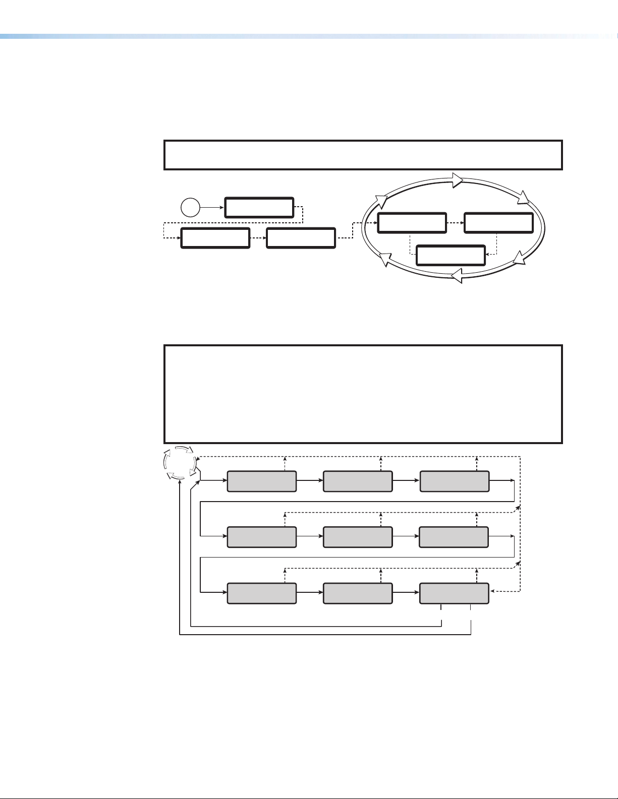
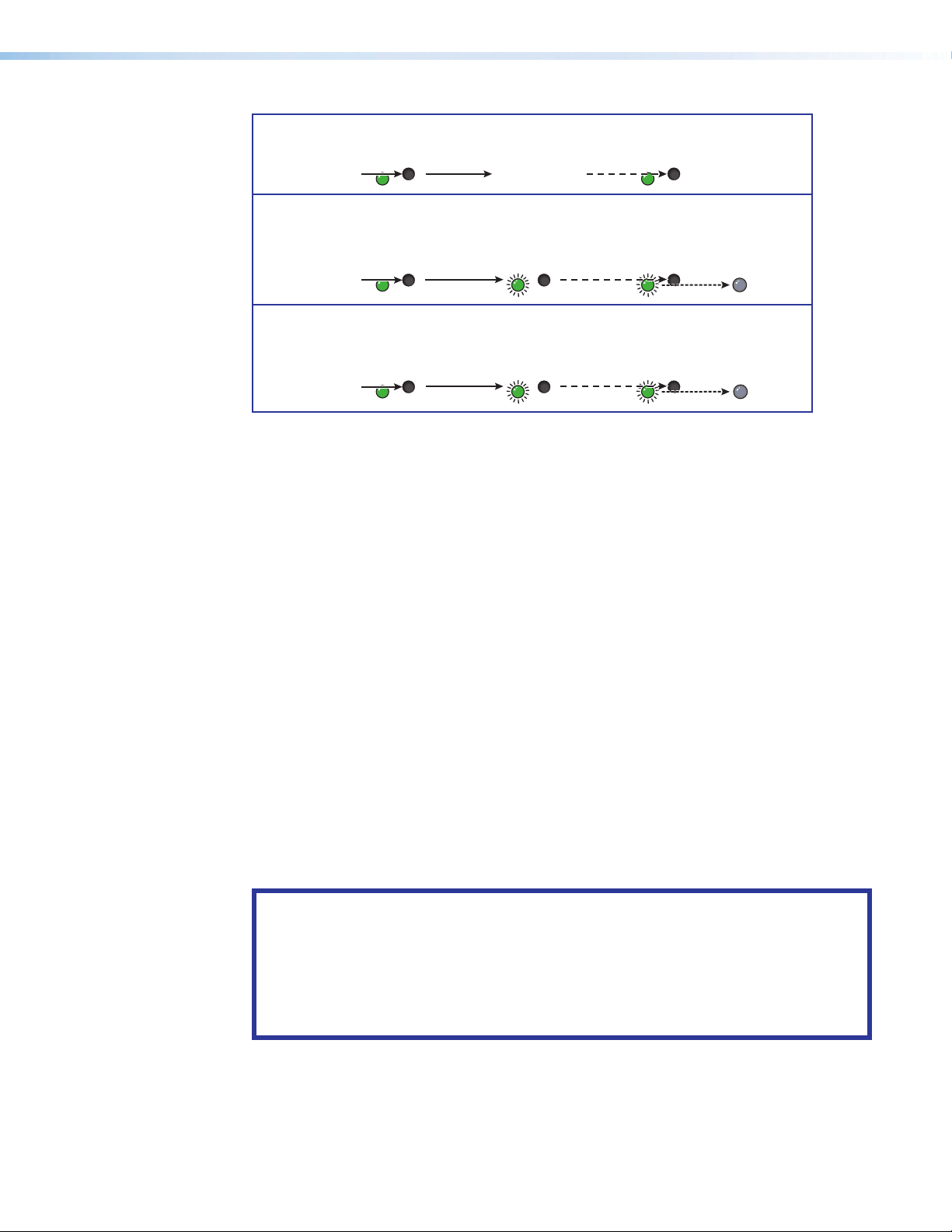
Menu Overview
After start-up, when no adjustments are actively being made, the default display cycle
(see figure9) runs on the menu display LCD. The screen progressively cycles through the
program and preview input format information, showing the number and video format of the
active input and the current output resolution.
NOTE: If a signal is not present on the currently selected input, No Valid Signal
appears in place of the input type (for example, Prev #4 No Valid Signal).
Power
on
Extron
ISS 608
Extron
Electronics
60-1684-01
FW Ver 1.00
Default Display Cycle
Prog #01 HDMI
1080p @60Hz
2
sec.
2
sec.
Output Rate
1080p @60Hz
Prev #08 DP
720p @60Hz
2
sec.
Figure 9. ISS Default Display Cycle
Press the MENU button once to bring up the first main (top level) menu (see figure9). Each
successive MENU button press cycles to the next main menu (see figure10 for a flowchart of
the main menus in the menu system).
NOTES:
• From any menu or submenu, after 30 seconds of inactivity, the ISS 608 times-out
to the default display cycle.
• In all the flowcharts in this chapter, solid lines indicate screen changes initiated by
the operator. Dashed lines indicate screen changes resulting from a timeout.
• A complete schematic of the menus and submenus is in the reference section (see
Front Panel Menu Diagrams on page77).
Default
Cycle
Menu
Input
Presets
30 sec. 30 sec. 30 sec.
Menu Menu
Picture
Controls
Input
Configuration
Menu
30 sec. 30 sec.
Background/Logo
Configuration
30 sec. 30 sec.
Exit Menu?
Press Next
Menu
Menu
Next
30 sec.
Menu
Menu
30 sec.
Output
Configuration
30 sec.
Advanced
Configuration
Menu Menu
Menu Menu
Effect
Configuration
View Comm
Settings
Figure 10. Menu System Flowchart
The top level menus are displayed, in order, on the LCD panel by pressing the MENU front
panel button. To return to the default cycle from a top level menu or submenu, press MENU
repeatedly until EXIT MENU? shows, then press NEXT.
Press NEXT when a menu displays to access its submenu. Within the submenu, press MENU
to exit the submenu and return to the currently active menu. Press NEXT to move to the next
submenu. Submenu details with configuration and options are on the following pages.
ISS 608 Seamless Switcher • Operation 14
Page 23
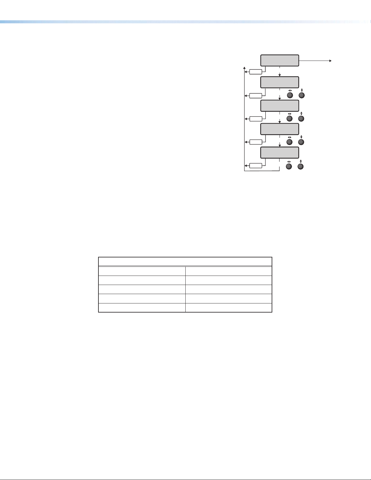
Input Presets Menu
From the Input Presets menu the user can
recall, save, and clear input presets from and to the
selected video bus (see figure11).
• From the default menu, press MENU to cycle to
the Input Presets menu.
• Press NEXT to enter the submenus.
• Press NEXT to advance to the relevant submenu:
Select Output, Recall Input Preset, Save
Input Preset, or Clear Input Preset.
• Within the submenu, use the ADJUST knobs to:
• Select the output to reference or affect.
• Recall the image configuration of the selected
Input Preset number to the selected video
bus.
• Save the image configuration of the selected
video bus to the selected Input Preset
number.
• Clear the image configuration of the selected Input Preset number.
• Then press NEXT to recall or save the selection.
• Press MENU to exit the submenu.
Menu
Menu
Menu
Menu
Menu
Input
Presets
NEXT
Select Output
Program
NEXT
Recall Input
Preset 001
NEXT
Save Input
Preset 002
NEXT
Clear Input
Preset 003
NEXT
or
or
or
or
MENU
Rotate to
select Program
or Preview
Rotate to
select a preset #
to recall
Rotate to
select a preset #
to save
Rotate to
select a preset #
to clear
Figure 11. Input Presets Menu
There are 128 input presets available to all inputs. These input presets are configured via SIS
commands (see SIS Configuration and Control starting on page35) using the settings
for the features in the table below.
Input Presets
Input preset name Image horizontal (H) position
Film mode Image vertical (V) position
Contrast Image horizontal (H) size
Brightness Image vertical (V) size
Detail
When an input preset is recalled, it fills the output based on the sizing and positioning it had
at the time it was saved. For example, if a video source was zoomed into when it was saved
as the full screen source, it is still zoomed in when it is recalled to the PIP window.
Input presets are saved per input.
ISS 608 Seamless Switcher • Operation 15
Page 24
Picture Controls Menu
From the Picture Controls menu
picture settings such as brightness and
contrast can be adjusted, as well as
perform a one-time Auto-Image on the
selected video bus.
• From the Picture Controls menu,
press NEXT to move to the desired
submenu.
• Within the submenu, use the
ADJUST knobs to select and change
values as required.
• Press MENU to exit the submenu.
NOTE: If a value is a default value,
an asterisk appears next to the
value. For example:
• Brit (brightness) = *064
• Cont (contrast) = *064
• Detail = *064
Auto-Image
Auto-Image automatically sizes and positions incoming video signal to fill the channel
window when a new input signal is detected.
Rotate either ADJUST knob to select Yes or No to perform an Auto-Image on the
selected video bus.
MENU
Menu
Menu
Menu
Menu
Menu
Picture
Controls
NEXT
Select Output
Preview
NEXT
Auto Image
No
NEXT
Brit Cont
*064 *064
NEXT
Detail
*064
NEXT
Rotate to
or
select Program
or Preview
Rotate to
select Yes
or
or No
Rotate
&
Rotate
Rotate to
adjust the sharpness
or
of the image
to adjust brightness
to adjust contrast
Figure 12. Picture Controls Menu
MENU
NEXT w Yes
selected
Press Next
to Confirm
NEXT
Brightness and Contrast
This submenu is used to adjust the brightness and contrast of the input signal. To use this
submenu:
• Rotate the horizontal ([) ADJUST knob to change the brightness of the video for the
selected input. The range of settings is 000 to 127. The default is *064.
• Rotate the vertical ({) ADJUST knob to change the contrast of the video for the selected
input. The range of settings is 000 to 127. The default is *064.
Detail
This submenu is used to adjust the detail of the input signal.
• Rotate either ADJUST knobs to adjust the detail of the video for the selected input. The
range of settings is 000 to 127. The default is *064.
ISS 608 Seamless Switcher • Operation 16
Page 25
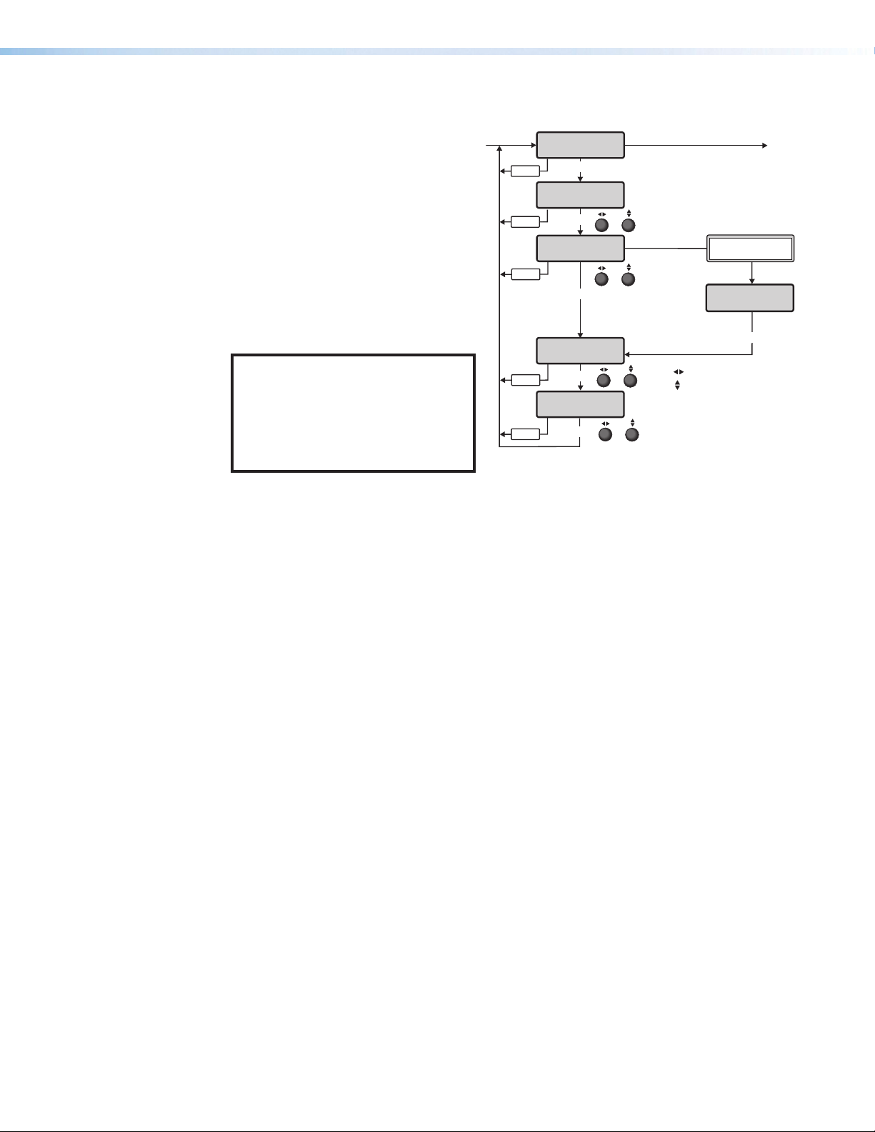
Input Configuration Menu
From the Input Configuration menu configure the settings for the inputs of the scaler
including Input format, Film mode, HDCP authorization, and input EDID.
From the Input Configuration menu, press NEXT to enter the submenus (see figure13).
Input Select
Rotate either ADJUST knob to select
the desired input number (see
figure13).
Film Detect
The Film Detect submenu turns
PAL film mode on and off for each
input. Film detection supports 2:2
and 3:2 detection. The processing
maximizes image detail and sharpness
for interlaced sources that originated
from film. Film detection is valid for
any interlaced input type. The ISS608
de-interlaces NTSC, PAL, and 1080i
inputs.
Rotate either ADJUST knob to select
Auto or Off.
Horizontal and Vertical Active
Values
This menu displays the horizontal and
vertical active values of the incoming
signal. These values can be viewed
only. They are not adjustable.
MENU MENU
Menu
Menu
Menu
Menu
Menu
Menu
Menu
Input
Configuration
NEXT
Input #1
HDMI
NEXT
Film Detect
Auto
NEXT
H Active V
1920 1080
NEXT
HDCP Authorized
Enabled
NEXT
Input #1 EDID
Auto
NEXT
Capture EDID
Program
NEXT
Rotate to
or
select an input
Rotate to
or
select Auto or Off
View active values
of the incoming signal
Rotate either to
&
enable or disable
Use to adjust resolution
&
or
to select rate
Use
Rotate either
to select
an output
If Program or
Preview selected
Save EDID to:
Slot 201
NEXT
Figure 13. Input Configuration Menu
or
Rotate either
to select a slot
HDCP Authorized
The user can disable HDCP communication for the current input. By default, the HDCP
Authorized option shows Enabled on all HDMI and DisplayPort inputs.
Rotate either ADJUST knob to select Enabled or Disabled.
Input EDID
EDID (Extended Display Identification Data) emulation is available on HDMI and DisplayPort
inputs. By default, all EDIDs are set to Auto. The selected input is displayed in the first line.
• Rotate the horizontal ([) ADJUST knob to select the desired EDID.
• Rotate the vertical ({) ADJUST knob to select the rate for select resolutions (see the
Scaler Resolution/EDID Emulation Table on page19).
Capture EDID
Capture the EDID from the connected displays. Rotate either ADJUST knob to select N/A,
Program, or Preview.
Save EDID to Slot
Save the selected EDID from the connected displays to a slot. Rotate either ADJUST knob to
select a slot 201 to 210.
ISS 608 Seamless Switcher • Operation 17
Page 26
Output Configuration Menu
From the Output Configuration menu the user can configure the settings for the outputs
of the scaler including output resolution, HDMI format, and HDCP notification.
From the Output Configuration menu, press NEXT to enter the submenus (see figure14).
Output Rate
Select the output resolution and refresh rate:
• Rotate the horizontal ([) ADJUST knob
to select one of the available output
resolutions.
• Rotate the vertical ({) ADJUST knob to select
the rate for select resolutions.
See Scaler Resolution/EDID Emulation
Table on page19 for the available
resolutions and rates.
The resolution is the same for the Program and
MENU MENU
Menu
Menu
Menu
Menu
Output
Configuration
NEXT
Output Rate
1080p @60Hz
NEXT
1A: HDMI Format
Auto
NEXT
HDCP Note
On: Green
NEXT
Rotate to select resolution
or
or
or
to select rate
Rotate
Rotate to select output
Rotate
to select format
Rotate to select type
to select
Rotate
the user image
Preview outputs.
Figure 14. Output Configuration Menu
HDMI Format
Select the HDMI format for each output:
• Rotate the horizontal ([) ADJUST knob to
select an output.
• Rotate the vertical ({) ADJUST knob to select
an HDMI format. The options are:
• Auto (default)
• DVI RGB 444
• RGB 444 FULL
• RGB 444 Limited
• YUV 444 Limited
• YUV 422 Limited
• YUV 420 Limited (available only for 3840x2160 and 4096x2160 resolutions)
HDCP Note
Select the HDCP notification to be displayed on the output when HDCP content is selected
but the connected display does not support HDCP:
• Rotate the horizontal ([) ADJUST knob to select the type of notification. The options
are:
• Green screen (default)
• Black screen
• User Image
• Rotate the vertical ({) ADJUST knob to select a user-created image file, if User Image is
selected.
NOTE: Upload images through PCS (see the ISS 608 PCS Help File).
ISS 608 Seamless Switcher • Operation 18
Page 27

Scaler Resolution/EDID Emulation Table
Automatic: Match Scaler Current Output Resolution**
Output 1A (Preview EDID export only)
0
1
Output 2A (Program EDID export only)
Resolution 23.98 Hz 24 Hz 25 Hz 29.97 Hz 30 Hz 50 Hz 59.94 Hz 60 Hz
640x480
800x600
1024x768
1280x768
1280x800
1280x1024
1360x768
1366x768
1440x900
1400x1050
1600x900
1680x1050
1600x1200
1920x1200
480p
576p
720p
1080i
1080p
2048x1080 (2K)
26
29 30 31 32 33
35 36
38 39 40 41 42 43 44
46 47 48 49 50 51 52
24
2048x1200
2048x1536
2560x1080
2560x1440
2560x1600
3840x2160
4096x2160***
Custom EDID/Output Rate #1
Custom EDID/Output Rate #3
Custom EDID/Output Rate #5
Custom EDID/Output Rate #7
Custom EDID/Output Rate #9
59 60 61 62 63 64 65
69 70 71 72 73 74 75
201
203
205
207
209
Custom EDID/Output Rate #2
Custom EDID/Output Rate #4
Custom EDID/Output Rate #6
Custom EDID/Output Rate #8
Custom EDID/Output Rate #10
2
10
11
12
13
14
15
16
17
18
19
20
21
22
23
25
34
37
45*
53
54
55
56
57
58
66
76
202
204
206
208
210
* Default output resolution
** Default EDID
*** Not available as an EDID, only as an output rate option
ISS 608 Seamless Switcher • Operation 19
Page 28

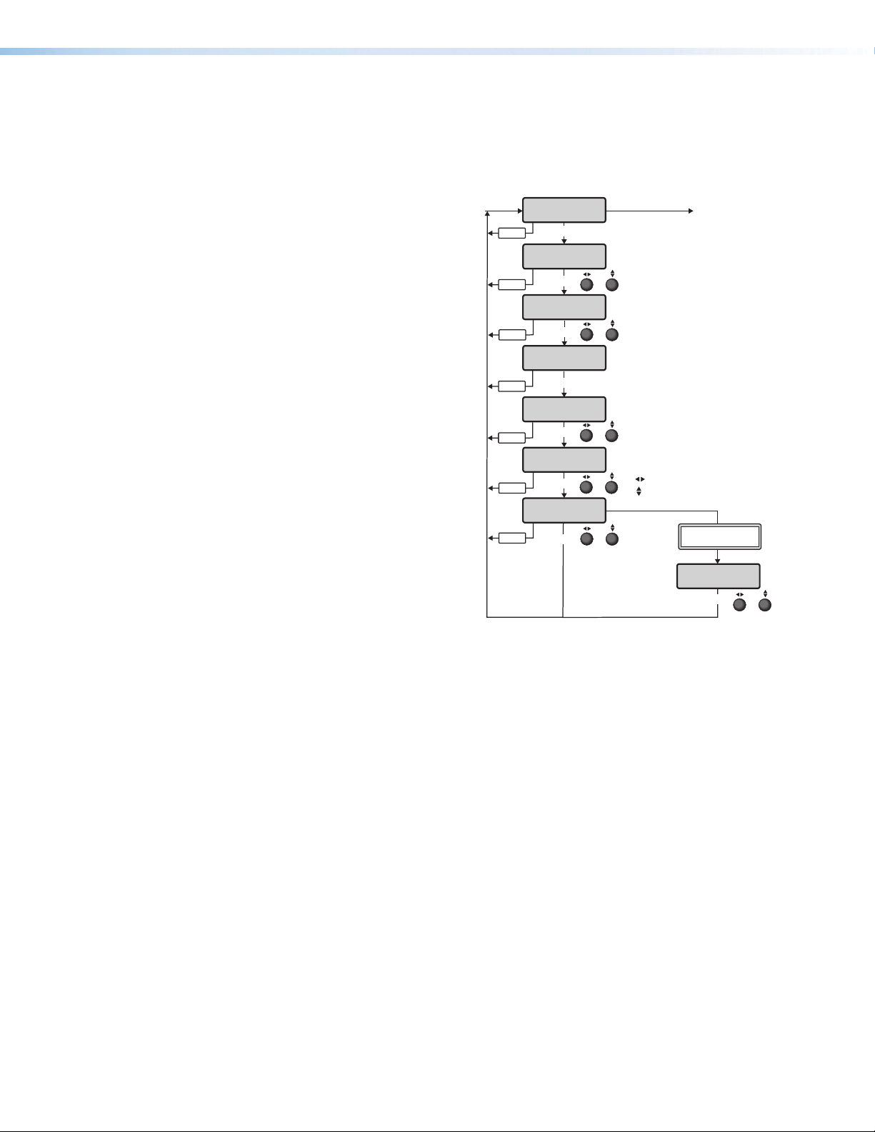
Effect Configuration Menu
Figure15 shows an overview of the Effect Configuration menu, the submenus, and the
available settings.
From the Effect Configuration menu, press NEXT to enter the submenus, and rotate
ether of the ADJUST knobs to scroll to the desired effect.
NOTE: The front panel effect button does not light when configuring the effect. The
effect button only lights when it is selected.
MENU
Menu
Menu
Effect
Configuration
NEXT
Effect
Dissolve
NEXT
Effect Duration
2 sec.
or
Rotate to
select an effect
or
MENU
NEXT w WIPE
selected
Wipe Direction
Soft Up
or
Rotate to
select wipe
direction
NEXT
Rotate to adjust effect duration
NEXT w PIP
selected
Recall PIP
Preset N/A
NEXT
Save PIP
Preset 001
NEXT
Clear PIP
Preset 002
NEXT
PIP Audio Follow
Main
NEXT
Rotate to
select a preset #
or
to recall
Rotate to
select a preset #
or
to save
Rotate to select
a preset #
or
to clear
Rotate to select
or
PIP or Main audio
NEXT w VIDEO KEY
selected
Video Key Effect
Level
or
NEXT w TRANS-
PARENCY selected
Video Key Effect
Transparency 128
or
Rotate to select
opacity level
NEXT
Rotate to select
a key effect
NEXT w LEVEL
Video Key Effect
Level 128
selected
Rotate to select
luminance level
NEXT
or
NEXT w RGB
selected
Video Key Effect
<R>GB 128
Rotate to select color
Rotate to adjust level
NEXT
&
Figure 15. Effect Configuration Menu
Dissolve
Set the duration of the dissolve effect applied when switching the preview output to the
program output:
1. From the Effect Dissolve submenu press NEXT. The Dissolve Duration submenu
displays.
2. Use either ADJUST knob to select the effect duration from 0.1 seconds to 5.0 seconds
in 0.1 second increments. The default is 0.5 seconds.
NOTE: Directly access the Effect Dissolve submenu by pressing the EFFECTS
DISSOLVE button.
ISS 608 Seamless Switcher • Operation 20
Page 29

Wipe
effect duration
effect duration
Set the wipe direction and duration of the wipe effect when switching the preview output to
the program output.
1. From the Effect Wipe submenu press NEXT. The Wipe
Direction submenu displays.
2. Use either ADJUST knob to select the direction of the wipe:
Soft Up, Soft Down, Soft Right, Soft Left, Hard Up,
Hard Down, Hard Right, or Hard Left (see figure16).
3. Press NEXT.
4. Use either ADJUST knob to select the effect duration from
0.1 seconds to 5.0 seconds in 0.1 second increments. The
default is 0.5 seconds.
NOTE: Directly access the WIPE submenu by pressing the
EFFECTS WIPE button.
Wipe Direction
Soft Up
NEXT
Rotate to select
wipe direction
Effect Duration
2 sec.
Rotate to select
or
or
WIPE UP SOFT
WIPE DOWN SOFT
WIPE RIGHT SOFT
WIPE LEFT SOFT
WIPE UP HARD
WIPE DOWN HARD
WIPE RIGHT HARD
WIPE LEFT HARD
Figure 16. Wipe Effects
PIP
Recall, save, or clear a PIP preset, select the audio source
while a PIP effect is active, and set the effect duration from this
menu.
The image in the preview output appears in the program output
as a picture-in-picture window using a dissolve effect and the
user-defined effect duration.
To recall a PIP preset:
1. Press the PIP button to go to the Recall PIP Preset
submenu.
2. Rotate the ADJUST knobs to select a preset (1 through
16) with the PIP image and window size and position
preconfigured.
3. Press the NEXT button to recall the selected preset.
To save a PIP preset:
Recall PIP
Preset N/A
NEXT
Save PIP
Preset 001
NEXT
Clear PIP
Preset 002
NEXT
PIP Audio Follow
Main
NEXT
Effect Duration
2 sec.
Rotate to
select a preset #
or
to recall
Rotate to
select a preset #
or
to save
Rotate to select
a preset #
or
to clear
Rotate to select
or
PIP or Main audio
or
Rotate to select
1. Press the PIP button and press NEXT to go to the Save PIP Preset submenu.
2. Rotate the ADJUST knobs to select a preset (1 through 16) with the PIP image and PIP
window size and position preconfigured (see the ISS 608 PCS Help File to preconfigure
a preset).
3. Press the NEXT button to save the selected preset.
ISS 608 Seamless Switcher • Operation 21
Page 30

To clear a PIP preset:
1. Press the PIP button and press NEXT twice to go to the Clear PIP Preset submenu.
2. Rotate the ADJUST knobs to select a preset (1 through 16) with the image and window
size and position preconfigured.
3. Press the NEXT button to clear the selected preset.
To select the audio source while the PIP effect is active:
1. Press the PIP button and press NEXT three times to go to the PIP Audio Follow
submenu.
2. Rotate the ADJUST knobs to select the audio (PIP or Main [default]) to route to the
output when in PIP mode.
3. Press the NEXT button to select the audio to output.
To define the effect duration:
1. Press the PIP button and press NEXT four times to go to the Effect Duration
submenu.
2. Rotate either ADJUST knob to select the effect duration from 0.1 seconds to
5.0seconds in 0.1 second increments. The default is 0.5 seconds.
3. Press the NEXT button.
When the PIP effect is selected, the preview output displays the input in a PIP window at
a preset, or user defined, size and position. Four predefined PIP presets allow the user to
place the PIP window in any of the four corners of the output raster. For a 1080p output, the
size and positions of the PIP presets are:
Default PIP Presets
PIP Preset Number Default Size Default Position
1, 5, 9, 13
2, 6, 10, 14
3, 7, 11, 15
4, 8, 12, 16
NOTE: Directly access the PIP submenu by pressing EFFECTS PIP.
424x240
424x240
424x240
424x240
30, 30 (left top corner)
1466, 30 (right top corner)
30, 810 (left bottom corner)
1466, 810 (right bottom corner)
Video Key
Configure the key effect type and
level for displaying the selected
preview source over the active
program video.
1. From the Video Key submenu
press NEXT. The Video Key
Effect submenu displays.
2. Rotate either ADJUST knob to
select a video key effect. The
options are: Transparency,
RGB, or Level.
3. Press NEXT.
4. For Transparency or Level, rotate either ADJUST knob to select the opacity level for
transparency or the luminance level for level, from 0 to 255. For RGB:
• Rotate the horizontal ([) ADJUST knob to select R, G, or B.
• Rotate the vertical ({) ADJUST knob to select the color tolerance, from 0 to 255.
NOTE: Directly access the Video Key submenu by pressing EFFECTS VIDEO KEY.
Video Key Effect
Level
or
NEXT w TRANS-
PARENCY selected
Video Key Effect
Transparency 128
or
Rotate to select
opacity level
NEXT
Rotate to select
a key effect
NEXT w LEVEL
Video Key Effect
Level 128
NEXT w RGB
selected
or
Rotate to select
luminance level
NEXT NEXT
selected
Video Key Effect
<R>GB 128
&
Use to select color
Use to adjust level
ISS 608 Seamless Switcher • Operation 22
Page 31

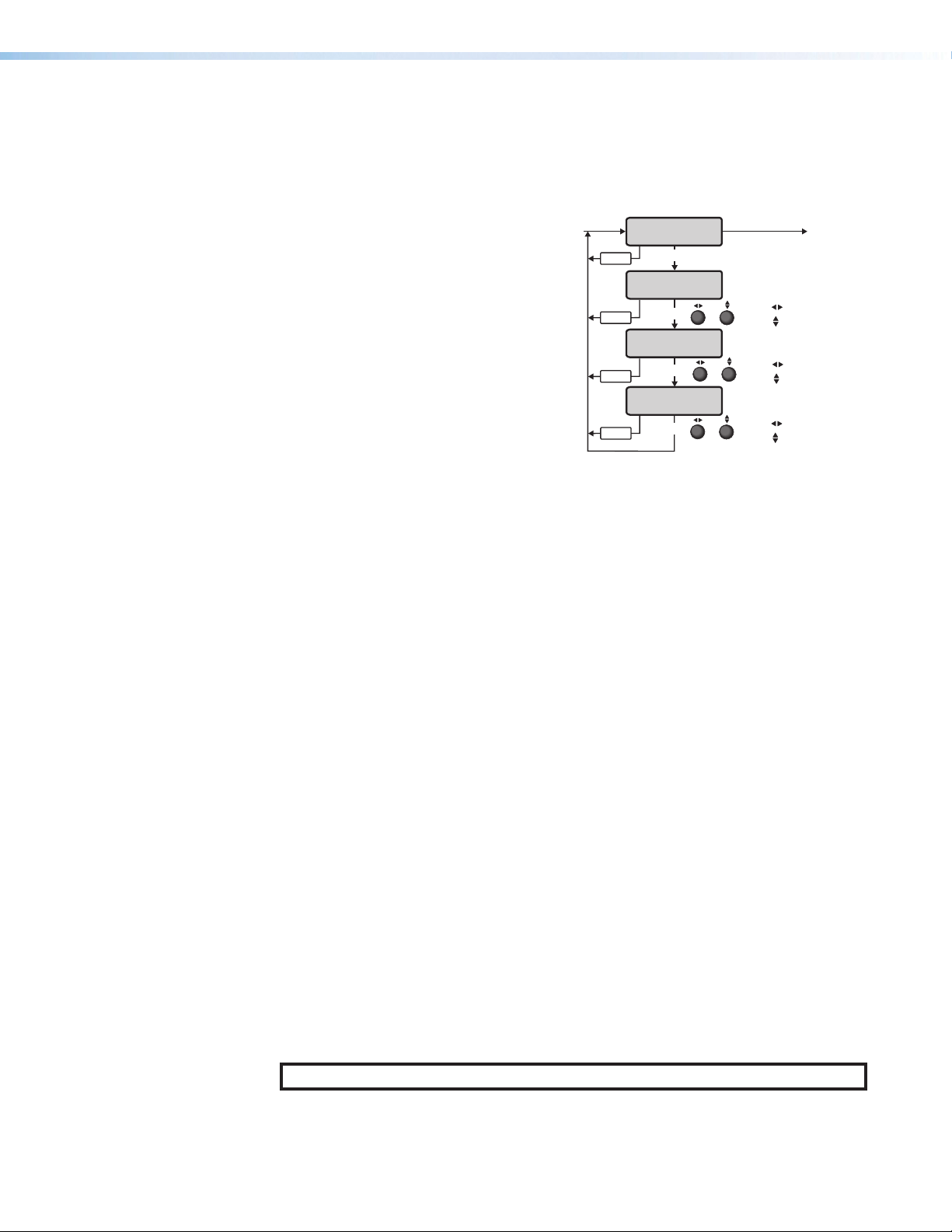
Background/Logo Configuration Menu
MENU MENU
Figure17 shows an overview of the Background/Logo Configuration menu, the
submenus, and the available settings.
Background Logo
Configuration
Menu
Menu
Menu
NEXT
Background Sel.
Color: Blue
&
NEXT
Logo Select
None
NEXT
Use to select preset
Use to assign the
image file
Use to select
type
Use to adjust color
or image file
or
User Color
is selected
User Color
<R>GB 128
NEXT
NEXT w Logo
preset w image file
assigned
H Logo Pos V
+0000 +0000
NEXT
Logo Key Effect
Off
&
&
or
Use to select color
Use to adjust level
Use to adjust
horizontal value
Use to adjust
vertical value
Rotate either to
select the
key effect
TRANSPARENCY
is selected
RGB
is selected
LEVEL
is selected
Alpha
is selected
Figure 17. Background/Logo Configuration Menu
Background Select
Select the image or color to be displayed as a background. By default, black is selected.
Position adjustments are not allowed for background images and all images are centered.
1. Rotate the horizontal ([) ADJUST knob to select image (IMG) or color.
NOTE: Upload images to the ISS 608 through PCS (see the ISS 608 PCS Help
File).
2. Rotate the vertical ({) ADJUST knob to select a user-created image if IMG: or a color if
Color:. Color options are: Black (default), Red, Green, Blue, White, Magenta, Cyan,
Yellow, or User Color.
For User Color:
• Rotate the horizontal ([) ADJUST knob to select R, G, or B.
• Rotate the vertical ({) ADJUST knob to select the color tolerance, from 0 to 255.
Logo Key Effect
Transparency 255
or
Rotate either to
adjust the level
Logo Key Effect
Level 128
&
Use to select the color
Use to adjust the level
Logo Key Effect
<R>GB 128
or
Rotate either to
adjust the level
ISS 608 Seamless Switcher • Operation 23
Page 32

Logo Select
Select the user created image to be saved to one of the 16 selected logo locations. By
default, no image is selected. The last logo location displayed is selected and activated
when the front panel LOGO button is pressed. The Logo Select menu is displayed when the
LOGO button is pressed to easily switch between logos.
NOTE: Upload images to the ISS 608 through PCS (see the ISS 608 PCS Help File).
1. Rotate the horizontal ([) ADJUST knob to select the logo preset number.
2. Rotate the vertical ({) ADJUST knob to select an image to assign to the logo preset
number.
3. Press NEXT
Logo Position
Adjust the horizontal and vertical position of the logo image. By default, the logo is located
at 0, 0.
1. Rotate the horizontal ([) ADJUST knob to adjust the horizontal position.
2. Rotate the vertical ({) ADJUST knob to adjust the vertical position.
3. Press NEXT
Logo Key Effect
Select and adjust the settings for the key effect to apply to a logo.
1. Rotate either ADJUST knob to select the key effect to apply to the logo. Options are:
• Off (default)
• Transparency — The amount of transparency of the image on the screen, which
determines the visibility of the video input through the logo.
• RGB — The levels of red, green, or blue to make transparent (key out) in the logo
image on the display.
• Level — Makes areas of the image that have a luma value at or below the set key
2. Press NEXT
3. Rotate either ADJUST knob to adjust the settings for the effect. Options are:
level value transparent.
• Alpha — If the logo image contains an alpha layer, selecting this item makes the
alpha layer transparent, so the video input shows through it.
• Transparency — 0 - 255 (Default = 255)
• RGB — 0 - 255 for each color (Default = 0 for each color)
• Level — 0 - 255 (Default = 0)
• Alpha — No adjustment
ISS 608 Seamless Switcher • Operation 24
Page 33

Advanced Configuration Menu
Rotate to select
Figure19 is an overview of the Advanced Configuration
menu, which allows for the configuration of advanced settings
including aspect ratio, auto memory, test patterns, screen
saver, and factory reset.
Test Pattern
From the Test Pattern submenu select a test pattern
(see figure18) to show on both outputs. The test patterns
are helpful when adjusting the connected displays for color,
convergence, focus, resolution, contrast, grayscale, and
aspect ratio.
• Rotate either ADJUST knob to select a test pattern.
The available test patterns are:
• Crop • Alt Pixels • Crosshatch
• Color Bars • Grayscale • Audio+Crop
Advanced
Configuration
Menu
Test Pa ttern
Menu
Aspect Ratio
Input 01 Follow
Menu
Auto Memory
Input 01 On
Menu
Screen Saver
Color: Black
Menu
Screen Svr Timeout
Menu
Preview Switch
Menu
Temperature
32.0C 89.6F
Menu
Factory Reset
Hold NEXT
Menu
NEXT
Off
NEXT
or
NEXT
&
NEXT
&
NEXT
&
Never
NEXT
Swap
NEXT
NEXT
NEXT
or
or
View temperature
of the device
Press and hold
NEXT button to reset
NEXT
Rotate to select
test pattern
Rotate to
select input
Rotate to select
Fill or Follow
Rotate to
select input
Rotate to select
On or Off
IMG or Color
Rotate to select
an image or color
Rotate to
select seconds
before timeout
Rotate to select
Swap or Stay
Figure 19. Advanced
Configuration
Menu
Figure 18. Test Patterns
Aspect Ratio
Select the aspect ratio for each input individually to fill the entire window for that channel
(Fill), or to allow each input rate to display in its native aspect ratio with respect to the
channel window (Follow) (see figure19).
1. Rotate the horizontal ([) ADJUST knob to select the input.
2. Rotate the vertical ({) ADJUST knob to select Fill (default) or Follow.
ISS 608 Seamless Switcher • Operation 25
Page 34

Auto Memory
Auto Memory is enabled on all inputs by default (see figure19 on page25). It should
only be disabled if the user desires to have a source applied to the input treated as a new
source, regardless of whether the source was detected previously.
Auto Memory saves the main window size, main image size , PIP image size and position,
brightness, contrast, and detail settings. Digital inputs are automatically set up using
information regarding image size and refresh provided by the digital input. This allows for
non-standard rates (not found in the input lookup table) to display correctly. Digital inputs
that do not match an existing lookup table are saved to Auto Memory as unique entries
based on the total line count, H/V active, and vertical refresh rate.
1. Rotate the horizontal ([) ADJUST knob to select the input.
2. Rotate the vertical ({) ADJUST knob to select On (default) or Off.
Screen Saver
Select a screen saver to display when an input with no detected source is routed to an
output (see figure19).
1. Rotate the horizontal ([) ADJUST knob to select Color or IMG.
2. Rotate the vertical ({) ADJUST knob:
• If Color was previously selected, select Black (default) or Blue.
• If IMG was previously selected, select a preconfigured image.
Screen Saver Timeout
Select whether the screen saver should timeout or remain until a new input is routed to the
output. Screen saver mode is activated when an input with no detected signal is routed to
an output (see figure19).
NOTE: If PIP or VIDEO KEY is enabled, the screen saver should not be enabled,
regardless of signal presence. If PIP or VIDEO KEY is enabled while in screen saver
mode, the ISS exits screen saver mode.
• Rotate either ADJUST knob to select a timeout setting. Options are: Never or a duration
from Instant (0) to 500 seconds in 1 second intervals.
Preview Switch Mode
Set the channel the preview output displays after a switch has occurred (see figure19).
• Rotate either ADJUST knob to select the preview switch mode. Options are: Swap
(default) or Stay.
• Swap mode — The preview and program outputs are swapped. The video and
audio signals on the preview output are applied to the program output. The video
and audio signals that had been applied to the program output are applied to the
preview output.
• Stay mode — The video and audio signals on the preview output are applied to
the program output and also continue on the preview output until another input is
selected.
Temperature
View the internal temperature of the unit. The temperature displays in both Celsius (°C) and
Fahrenheit (°F) (see figure19).
ISS 608 Seamless Switcher • Operation 26
Page 35

Factory Reset
Reset the ISS608 to the default values. This reset is the same as the ZXXX reset via SIS
commands (see Soft reset on page55).
• Press and hold the NEXT button. The LCD window displays Factory Reset Please
Wait while the unit is resetting. When the reset is complete, release the NEXT button.
View and Edit Communications Settings Menu
Figure20 is an overview of both the View User
Comm Settings and the Edit User Comm
Settings menus, the submenus, and the
available settings.
The default menu is View Comm Settings and
all of the submenus are display only, unable to
be edited. To access the Edit Comm Settings
menu and submenus, press and hold the NEXT
button until the menu changes to Edit Comm
Settings. Release the NEXT button.
Serial Port
The read-only Serial Port submenu displays
the baud rate of the ISS608 rear panel RS-232
port. This is a read-only submenu in both the
View Comm Settings menu and the Edit Comm
Settings menu (see Serial port configuration
on page55 to configure via SIS commands).
MAC Address display
The read-only MAC Address display shows the
hardcoded, factory assigned hardware address.
This is a read-only submenu in both the View
Comm Settings menu and the Edit Comm
Settings menu.
DHCP Mode
The DHCP Mode submenu displays the on or off status of the Dynamic Host Configuration
Protocol (DHCP) method of IP addressing. If DHCP is on, the switcher ignores any entered
IP addresses and obtains its IP address from a DHCP server (only if the network is DHCP
capable).
From the Edit Communications Settings menu, rotate either ADJUST knob to select DHCP
Mode. Options are ON or OFF (default).
NEXT
Menu
Menu
Menu
Menu
Menu
Menu
Menu
View Comm
Setting
Press and hold
NEXT
NEXT to edit fields
Serial Port
9600 RS232
NEXT
MAC Address
0005A6003C24
NEXT
DHCP Mode
Off
NEXT
IP Address
192.168.254.254
NEXT
Subnet Mask
255.255.0.0
NEXT
Gateway Address
0.0.0.0
NEXT
NEXT
View the baud rate of
the RS-232 port
View factory set
MAC address
Rotate to select
or
On or Off
Rotate to select octet field
&
Rotate to change address
Rotate to select octet field
&
Rotate to change address
Rotate to select octet field
&
Rotate to change address
Figure 20. View and Edit
Communication Settings
Menu
Exit Menu?
Press Next
ISS 608 Seamless Switcher • Operation 27
Page 36

Exit Menu
30 sec.
IP Address, Subnet Mask, and Gateway Address
These submenus display the ISS608 IP address, subnet mask, and gateway server
address (if any) (see figure20 on page27).
Valid IP addresses consist of four 1-, 2-, or 3-digit numeric subfields, properly called octets,
separated by dots (periods). Each octet can be numbered from 000 through 255. Leading
zeroes, up to 3 digits total per octet, are optional. Values of 256 and above are invalid.
Contact the local system administrator for these addresses.
NOTE: If the local system administrators have not changed the value, the factory-
specified default IP address, 192.168.254.254, is the correct value for this field.
When these submenus are selected from the Edit Comm Settings menu:
• Rotate the ([) ADJUST knob to select an octet to edit.
• Rotate the ({) ADJUST knob to change the value of the selected octet.
From the Exit menu (see figure21), press the NEXT button to return to the default display
cycle, or press the MENU button to return to the beginning, the Input Presets menu.
Input
Presets
Menu
Picture
Control
Menu
Input
Configuration
Menu
Output
Configuration
Menu
Effect
Menu
Configuration
Menu
Background/Logo
Configuration
Menu
Advanced
Configuration
Menu
View Comm
Settings
Menu
Exit Menu?
Press Next
Menu
Menu
Next
*
Default
Cycle
Figure 21. Exit Menu
ISS 608 Seamless Switcher • Operation 28
Page 37

Front Panel Button Operations
The following information details features and functions of the front panel buttons.
Front Panel Button Shortcuts
Front panel buttons can be used as shortcuts to the related LCD menu item, making it
easier to change settings without navigating through the entire LCD menu. These button
presses are shortcuts only and the standard LCD menu structure and timeouts should be
followed. Please see the table below for details.
Front Panel Button Goes to LCD Menu Submenu
DISSOLVE
CUT
WIPE
VIDEO KEY
PIP
LOGO
RECALL/SAVE
Effect Configuration
NA
Effect Configuration
Effect Configuration
Effect Configuration
Background/Logo
Configuration
Layout Presets
Effect Duration
NA
Wipe Direction
Video Key Effect
Recall PIP Preset
Logo Select
First press = Recall Layout Preset
Press and hold 2 seconds = Save
Layout Preset
Front Panel Button Colors
Front Panel Button Button Color Condition
Input buttons
FREEZE
MUTE
EFFECTS
PRESETS RECALL/
SAVE
ENTER
SIZE AND POSITION
MENU AND NEXT
TAKE
• Off
• Amber
• Green
• Red
• Off
• Amber
• Off
• Amber
• Red
• Off
• Amber
• Flash Green
• Flash Amber
• Amber
• Amber
• Amber
• Amber
• Amber
• Not tied to an output
• Audio and video tie
• Video only tie
• Audio only tie
• Off
• Activated
• Off
• Video mute
• Sync mute
• Off
• Effect selected
• LOGO button pressed but no logo assigned
• Effect is on Program output
• Preset Save or Recall LCD menu is active
• When pressed and Preset is Saved or
Recalled
• When Size or Position LCD menu is active
• Always
• Always
ISS 608 Seamless Switcher • Operation 29
Page 38

Selecting an Input
• Press and release the desired PROGRAM or PREVIEW input selection button. The button
lights and the selected input displays on the program or preview monitor.
• Press the MUTE or FREEZE buttons to mute or freeze the PROGRAM or PREVIEW output
video.
Switching the Preview Output to the Program Output
1. Press and release a preview input button.
2. Press and release one of the EFFECTS buttons.
• CUT — This effect does not need to be configured. When used, the image instantly
swaps between the preview output and the program output without any effect.
• DISSOLVE — The previous program output fades out while the image from the
preview output fades into the program output using the user-defined duration. To
configure, see Dissolve on page20.
• WIPE — The image in the preview output “unrolls” over the top of the program
output using the user-defined duration and direction. To configure, see Wipe on
page21.
• PIP — The image in the preview output appears in the program output as a
picture-in-picture window using a dissolve effect and the user-defined duration. To
recall a PIP preset, see PIP on page21.
• VIDEO KEY — Video on the preview bus can be keyed to appear over the
existing video on the program bus, using an RGB key, a luminosity level key, or a
transparency effect. To configure, see Video Key on page22.
3. Press and release the TAKE button to execute the selected effect.
Recalling a Layout Preset
Layout presets are used to preconfigure a presentation prior to going live (see the
ISS608PCSHelpFile to configure a layout preset). This minimizes missed cues or incorrect
video layout. A layout preset captures transition effect settings, a logo preset, the input
channel, and any picture control adjustments made to the preview output (for a list of all the
layout preset options, see the Layout Presets table below). When recalled, layout presets
apply the settings to the preview output to review the configuration before TAKE is pressed
to make it live on the program output.
Layout Presets
Selected effect
Effect duration
Wipe effect type
Video Key effect type
Video Key effect levels
Logo preset
Window size
Window position
Image position
Image size
Contrast
Brightness
Detail
Background image
Selected preview input
ISS 608 Seamless Switcher • Operation 30
Page 39

Default
MENU
Cycle
Default
Cycle
Menu
Press
Recall/Save
Recall Layout
N/A
ENTER ENTER
Preset ###
Recalled
1 sec.
Rotate either to select.
or
Press ENTER to recall
or save the layout
Press and Hold
Menu
Recall/Save
2 sec.
Save Layout
N/A
or
Preset ###
Saved
1 sec.
Figure 22. Recall/Save Menu
To recall or save a layout preset:
1. Press the RECALL/SAVE button (see figure22) to go to the Recall Layout menu.
2. Rotate either ADJUST knob to select a saved layout preset.
3. Press the ENTER button to recall the selected preset to the preview output.
Configuring and Recalling a Logo Preset
NOTE: User images must first be uploaded via Extron Product Configuration Software
(PCS) available at www.extron.com.
To configure a logo preset:
1. Press the MENU button to go to the
Background/Logo Configuration menu.
2. Press the NEXT button to go to the Logo
Select submenu.
3. Rotate the horizontal ([) ADJUST knob to
select the logo preset to configure.
4. If needed, rotate the vertical ({) ADJUST knob
to change the assigned image file (the image
file shows on the preview output).
5. Press the NEXT button to adjust the position of
the logo.
6. Rotate the ([) ADJUST knob to adjust the
horizontal (H) position and rotate the ({)
ADJUST knob to adjust the vertical (V) position.
7. Press the NEXT button to select a Logo Key
Figure 23. Configure Logo
Effect, if desired.
8. Rotate either ADJUST knob to select the Logo Key Effect:
• Transparency — Applies a transparency level (0-255) to the entire graphic. A setting
of 0 transparency indicates 100% opacity. No content below the graphic is mixed.
• RGB — Defines an RGB color (0-255) to be keyed out of the image. This setting
supports signals which may have color noise or slight variance in brightness.
• Level — Defines a luminance level (0-255) in which any video information with a
luminance below the defined value is keyed out of the layer
• Alpha — Uses the alpha layer data found in the graphic file. Only PNG files containing
alpha data are supported.
Background Logo
Configuration
Menu
Background Sel.
IMG: Unassigned
Menu
Logo Select
01: Unassigned
Menu
H Logo Pos V
+0000 +0000
Menu
Logo Key Effect
Menu
NEXT
NEXT
NEXT
NEXT
Off
NEXT
Rotate to select
type
&
Rotate to adjust color
or image file
Rotate to select preset
&
Rotate to assign the
image file
Rotate to adjust
horizontal value
&
Rotate to adjust
vertical value
Rotate to
select logo
or
key effect
ISS 608 Seamless Switcher • Operation 31
Page 40

To recall a logo preset:
1. Press the LOGO button (if no logo preset was previously selected, Logo Error shows on
the LCD screen for 2 seconds). The Logo Select menu shows in the LCD screen.
2. Rotate the ([) ADJUST knob to select the logo preset.
3. Wait a second or press the NEXT button and the logo preset is recalled onto the preview
output.
4. Press the TAKE button to switch the preview output, with the included logo preset, to
the program output using the selected effect, displaying the logo preset on the program
output.
A different logo preset can be recalled or removed on the preview output by pressing
the LOGO button again.
5. Press the TAKE button again to switch the preview output to the program output.
• If a different logo preset was recalled on the preview output, the new logo preset is
displayed on the program output.
• If no logo preset is on the preview output, the logo on the program output is
removed.
NOTE: The LOGO button lights solid if there is a logo on preview output but not on
program output. The LOGO button blinks if there is a logo on program output whether
there is a logo on preview output or not.
Adjusting the Size and Position of the Program or Preview
The size and position of the program or preview image can be adjusted using the ADJUST
SIZE and POSITION buttons.
• Press the SIZE or POSITION
buttons to toggle between
the PREVIEW image and the
PROGRAM image adjustments.
• When the PIP effect is
selected, press the SIZE and
POSITION buttons to cycle
through the PIP window, PIP
H Pre Img Size V
+1920 +1080
Rotate [ to set horizontal.
Rotate { to set vertical.
H Pro Img Size V
+1920 +1080
Rotate [ to set horizontal.
Rotate { to set vertical.
image, and program image
adjustments.
H PIP Img Size V
+1920 +1080
Rotate [ to set horizontal.
Rotate { to set vertical.
H PIP Win Size V
+1920 +1080
Rotate [ to set horizontal.
Rotate { to set vertical.
Figure 24. Size and Position Menus
NOTE: Image adjustments can be made via PCS, SIS commands, and the front panel
LCD. Window adjustments can be made via PCS and SIS commands only. By default,
the window size matches the output raster unless in PIP mode.
• Window position refers to the window size and position within the output raster.
• Image position refers to the size and position of the image within the window.
H Pre Img Pos V
+0000 +0000
Rotate [ to set horizontal.
Rotate { to set vertical.
H Pro Img Pos V
+0000 +0000
Rotate [ to set horizontal.
Rotate { to set vertical.
H PIP Img Pos V
+0000 +0000
Rotate [ to set horizontal.
Rotate { to set vertical.
H PIP Win Pos V
+0000 +0000
Rotate [ to set horizontal.
Rotate { to set vertical.
ISS 608 Seamless Switcher • Operation 32
Page 41

Matrix Mode
The ISS can be set to Matrix Mode, which allows an upstream Extron matrix switcher to
be used as a seamless switcher. When a matrix switcher is connected upstream of the
ISS608, all of the matrix inputs essentially become inputs to the ISS608 and transition
effects can be automatically applied to the source switches.
Matrix Mode only works with HDMI inputs 1 and 2 and requires the matrix switcher to toggle
source routes between these two connections.
To use Matrix Mode:
• Initially, Program is set to input 1 and Preview is set to input 2. Preview switch setting
is set to SWAP, and switch effect is set to CUT. The switch effect can be changed to
DISSOLVE or WIPE if desired using SIS or PCS.
• Use the matrix switcher to route the new source to the matrix output connected to the
ISS input currently selected on the Preview bus (initially input 2).
• The ISS608 automatically performs a seamless switch with the selected effect (CUT,
WIPE, or DISSOLVE) when new video is acquired and stable on the Preview channel
input.
• The next source to be displayed must now be routed to the opposite ISS input
previously routed to, because the Program and Preview channels have been swapped.
NOTE: When in this mode, the front panel is completely locked.
Consider an example system where a matrix switcher has outputs 11 and 12 connected to
ISS 608 inputs 1 and 2, respectively.
• When Matrix Mode is initially enabled, the source tied to matrix output 11 is currently live
on the Program output and the source tied to output 12 is on the Preview output.
• The first switch on the matrix should be to output 12, at which point the ISS seamlessly
switches to that source.
• The next switch on the matrix should be to output 11, which triggers the ISS to
seamlessly switch back.
• The following switch would be to output 12 on the matrix, and the toggling between
output 11 and 12 on the matrix would continue as needed.
ISS 608 Seamless Switcher • Operation 33
Page 42

Upstream Signal Switching and Local Video Bus Switching
Whether switching from an upstream switcher or from the local ISS inputs, detection of loss
of sync and acquisition of the new signal on the video bus (Program or Preview) must be
managed properly to accomplish a pseudo seamless switch.
Select from the following options to customize how new inputs automatically transition to
the output when the signal is lost (see Upstream/Local effect select on page53 SIS
command or the ISS608PCSHelpFile to configure):
• Cut through black — The video in the window immediately mutes to black and cuts to
the new signal once it is applied (default).
• Fade through black — The window freezes the last solid frame of the old signal and
fades down to black and fades the new signal on once it is applied.
• Seamless cut — The window freezes the last solid frame of the old signal and
seamlessly cuts to the new signal once it is applied. If no signal is applied for 1second,
the image within the window cuts to black.
• Seamless fade — The window freezes the last solid frame of the old signal and
performs a seamless dissolve to the new signal once applied. If no signal is applied for
1second, the image within the window fades to black.
• Low Latency — The video in the window immediately mutes to black when the signal
is lost and cuts to the new signal once it is applied. A frame of video delay is removed
from the product video processing logic and may introduce video artifacts during the
upstream switch effect.
ISS 608 Seamless Switcher • Operation 34
Page 43

SIS Configuration and Control
The topics covered in this section are:
• Connections Options
• Host-to-Switcher Communications
• Switcher-Initiated Messages
Connections Options
The ISS608 can be configured and controlled using SIS commands or embedded web
pages. Configure and control the ISS608 remotely via a host computer or other device
(such as a control system) by connecting to the rear panel RS‑232 port, LAN port, or the
front panel USB Config port of the ISS device.
Rear Panel RS-232 Port
• Using the Command and Response Tables
• Command and Response Tables
The ISS608 has a rear panel serial port (see figure2, H on page6) that can be
connected to a host device such as a computer running a HyperTerminal utility, or the
Extron DataViewer utility. The port makes serial control of the ISS possible. Use the protocol
information listed below to make the connection (see Host-to-Switcher Communications
on page36).
The default protocol for the port is as follows:
• 9600 baud • no parity • 8 data bits
• 1 stop bit • no flow control
The ports can be configured to operate at the 9600, 19200, 38400, or 115200 baud rate.
NOTE: The switcher can operate at 9600, 19200, 38400, or 115200 baud rates (see
Serial port connection on page10 to configure the rear panel RS‑232 port from
the front panel).
Front Panel Configuration USB Port
The mini B USB port is located on the front panel (see figure8, F on page11). Connect
to a host computer for configuration using SIS commands with DataViewer, available at
www.extron.com. To connect the ISS608 to a host computer, download the USB driver,
follow the on‑screen instructions, and configure the ISS as required.
Ethernet Link
The rear panel Ethernet connector on the switcher (see figure2, G) can be connected
to an Ethernet LAN or WAN. This connection makes SIS control of the switcher possible
using a computer connected to the same LAN or WAN (see Wiring the network cable on
page10 to wire the LAN connection).
ISS 608 Seamless Switcher • SIS Configuration and Control 35
Page 44

Default Address
To access the switcher via the LAN port, the switcher IP address is needed. If the address
has been changed to an address comprised of words and characters, the actual numeric
IP address can be determined
Settings Menu on page27), PCS (see Device Menu on page66 ), or the internal
web page (see Network Settings Panel on page71
changed, the factory‑specified default is 192.168.254.254.
Symbols
Symbols (X/ values), defined below, are used throughout the discussions of the switcher‑
initiated messages that begin on the next page and the Symbol definitions starting on
page39. The symbols represent variables in the switcher‑initiated messages and the
Command and Response table fields.
Host-to-Switcher Communications
The switcher accepts SIS commands through its serial port, USB config port, or LAN port.
SIS commands consist of one or more characters per command field. They do not require
any special characters to begin or end the command character sequence. Each switcher
response to an SIS command ends with a carriage return and a line feed (CR/LF = ]),
which signals the end of the response character string. A string is one or more characters.
using the front panel (see View and Edit Communications
). If the address has not been
Switcher-Initiated Messages
When a local event such as power‑up or a front panel operation occurs, the switcher
responds by sending a message to the host. The switcher‑initiated messages are listed on
the following pages. The switcher does not expect a response from the host, but the host
program may request a new status.
Power-up
(c) Copyright 2019, Extron Electronics, ISS 608 Series, Vx.xx, 60-nnnn‑nn]
Tue, 15 Aug 2019 10:14:07]
The copyright message is displayed upon connecting to the ISS via TCP/IP or after a power
cycle via RS‑232. 60‑nnnn‑nn is the product part number. Vx.xx is the firmware version
number.
Input Frequency Change
ReconfigX!] Broadcast upon detection of any change of the input frequency for
the input has occurred. X! is the input number.
In00•X6!*X6!*...*X6!] Broadcast upon detection of any change of the input video
presence.
Hot Plug and HDCP Events
HplgO
X@*X6(] Broadcast upon detection of a Hot Plug event on the HDMI
outputs.
HdcpI
X!*X4$] Broadcast upon detection of a change in the HDCP status of
input X!.
ISS 608 Seamless Switcher • SIS Configuration and Control 36
Page 45

HdcpO
X@*X4$] Broadcast upon detection of a change in the HDCP status of
output X@.
Effect Select
SwefO1*
X1(] Broadcast upon selection of a new effect (for example: dissolve,
cut, wipe, video key, and PIP).
Logo Event
LogoE
X@* X8)] Broadcast when a Logo is turned on for output X@.
LogoE
X@*0] Broadcast when a Logo is turned off for output X@.
Take Event
Tke] Broadcast upon a Take event.
Bsy1] Broadcast upon the start of a Take effect.
Bsy0] Broadcast upon the completion of a Take effect.
Video Mute Event
Vmt
X@*1] Broadcast when video is muted on output X@.
Vmt
X@*2] Broadcast when video and sync are muted on output X@.
Vmt
X@*0] Broadcast when video is unmuted on output X@.
Video Freeze Event
Frz
X@*1] Broadcast when video is frozen on output X@.
Frz
X@*0] Broadcast when video is unfrozen on output X@.
Switcher Error Responses
When the switcher receives an SIS command and determines that it is valid, it performs the
command and sends a response to the host device. If the switcher is unable to perform
the command because the command is invalid or contains invalid parameters, the switcher
returns an error response to the host. The error response codes are:
• E01 — Invalid input number • E17 — Invalid command for signal type
• E10 — Invalid command • E22 — Busy
• E11 — Invalid preset number • E24 — Privilege violation
• E12 — Invalid port or output number • E25 — Device not present
• E13 — Invalid parameter • E26 — Maximum number of connections
exceeded
• E14 — Invalid for this configuration • E28 — Bad Filename / File not Found
NOTE: If the unit does not support or recognize the entered commands, no response is
issued.
ISS 608 Seamless Switcher • SIS Configuration and Control 37
Page 46

Using the Command and Response Tables
Space
The Command and Response table begins on the next page. The table below shows the
hexadecimal equivalent of each ASCII command.
ASCII to Hex Conversion Ta ble
NOTE: For commands and examples of computer or device responses used in this
guide, the character “0” is used for the number zero and “O” is the capital letter “o.”
•
ISS 608 Seamless Switcher • SIS Configuration and Control 38
Page 47

Symbol definitions
]
}
or |
E
or W
X!
X@
X#
X^
X&
X*
X(
X1)
X1@
X1#
X1$
X1%
CR/LF (carriage return/line feed)
=
Carriage return
=
or pipe symbol (no line feed, hex = 0D)
Space
• =
Escape
=
Input selection 1 to 8 (two‑digit response with 0
=
padding)
Output selection (two‑digit response with 0 padding)
=
1* = Preview (1A ‑ HDMI ‑ for mute or format type
commands)
2* = Program (2A ‑ HDMI ‑ for mute or format type
commands)
5 = Analog Preview (Analog audio – for mute or
format type commands only)
6 = Analog Program (Analog audio – for mute or
format type commands only)
NOTE: *Values 1 and 2 can apply to global
settings on a bus (for example: input
switching)
Input format
=
0 = No signal
1 = HDMI
2 = DVI
3 = DisplayPort
Total lines (four‑digit response – 0 padding)
=
Total pixels (four‑digit response – 0 padding)
=
Active pixels (four‑digit response – 0 padding)
=
Active lines (four‑digit response – 0 padding)
=
Enable/disable
=
0 = OFF/disable
1 = ON/enable
Internal temperature in Celsius (two‑digit response – 0
=
padding)
Horizontal and Vertical frequencies (formatted three
=
digits with single decimal and leading zeros)
(for example: 075.3)
Text label – Up to 32 characters but cannot contain ,
=
(comma) ,*, or |.
Default name for unsaved locations = [unassigned]
Default name for inputs = Input xx (Input 07)
Default name for saved Layout preset name =
Layout Preset xxx (Layout Preset 005)
Default name for saved Input preset name = Input
Preset xxx (Input Preset 005)
Default name for saved PIP preset name = PIP
Preset xx (PIP Preset 05)
Default name for saved Logo name = Logo xx
(Logo 05)
Picture adjustment – 0 to 127 (Default = 64)
=
(three‑digit response – 0 padding)
X1^
X1&
X1*
H and V position (five‑digit response with 0 padding
=
and leading “+” or “–” symbol)
NOTE: Position is ±4096 horizontally and
±2160 vertically.
H and V size (five‑digit response with 0 padding and
=
leading “+” or “–” symbol)
NOTE: Size is up to 8192 horizontally and
4320 vertically. Minimum H/V size is 10.
Image/Window number
=
1 = Preview
2 = Program/Main
3 = PIP
X1( Take video effect
0 = Cut
1 = Dissolve
2 = Wipe
3 = PIP
4 = Video key
X2) Wipe switch effect
1 = Soft wipe up 5 = Hard wipe up
2 = Soft wipe down 6 = Hard wipe down
3 = Soft wipe right 7 = Hard wipe right
4 = Soft wipe left 8 = Hard wipe left
X2!
X2@
X2#
X2%
X2^
X2&
Scaler resolution/EDID emulation
=
(three‑digit response – 0 padding) (see Scaler
Resolution/EDID Emulation Table on page42)
Test patterns (two‑digit response ‑ 0 padding)
=
0 = Off (Default)
1 = Crop
2 = Alternating Pixels
3 = Crosshatch
4 = Color Bars
5 = 32‑level split grayscale
6 = Audio test (Crop pattern and outputs
Pink Noise: CH 1/2, 48 kHz, 24 bit)
Upstream/local effect
=
0 = Cut through black ‑ Cut to black on loss or
change of sync (Default)
1 = Fade thru black ‑ Freeze last frame on loss or
change of sync and immediately fade to black.
2 = Seamless fade ‑ Freeze last frame on loss or
change of sync and seamlessly dissolve to new
signal when locked.
3 = Seamless cut ‑ Freeze last frame on loss/change
of sync and seamlessly cut to new signal when
locked.
4 = Low latency ‑ Cut to black on loss/change of
sync. Also removes one frame of video delay
which may introduce video artifacts during the
switch transition.
Layout Presets — 1 to 128
=
(three‑digit response — 0 padding)
Input Presets — 1 to 128
=
(three‑digit response — 0 padding)
PIP Presets — 1 to 16
=
(two‑digit response — 0 padding)
ISS 608 Seamless Switcher • SIS Configuration and Control 39
Page 48

X2*
X2(
X3)
X3!
X3@
X3#
X3$
X3%
X3(
X4)
X4@
X4$
Output sync timeout (Default = 501 – Never)
=
(three‑digit response – 0 padding)
0 = output sync is instantly disabled with no active
video on any of the inputs
1 to 500 (1 second increments)
501 = output sync never times out
Executive mode status:
=
0 = Off/disabled (Default)
1 = Mode 1 ‑ Complete front panel lockout
2 = Mode 2 ‑ Partial front panel lockout
(Menu and Next buttons disabled)
3 = Mode 3 ‑ Program lockout (all changes to
Program are locked out)
Auto switch mode
=
0 = Off/manual input switching only (Default)
3 = Matrix Mode
= Baud rate — 300, 600, 1200, 1800, 2400, 3600,
4800, 7200, 9600 (Default), 14400, 19200, 28800,
38400, 57600, 115200
Parity — Odd, Even, None (Default), Mark, Space
=
(only the first letter is required)
Data bits — 7 or 8 (Default)
=
Stop bits — 1 (Default) or 2
=
Configuration type
=
0 = IP configuration (ip.cfg)
2 = Unit‑specific parameters (box.cfg)
NOTE: Configuration files are stored in the
directory /nortxe-backup, created on the
unit by the Save command.
Aspect ratio setting
=
1 = Fill (each input automatically fills the entire
output raster; Default)
2 = Follow (each input is displayed in its native
aspect ratio)
Screen saver modes
=
1 = Black screen (Default)
2 = Blue screen
3 = User image
Mute
=
0 = OFF/disable
1 = Mute to black
2 = Mute output sync and video
HDCP status
=
0 = No sink or source device detected
1 = Sink or source detected but no HDCP
2 = Sink or source detected with HDCP
X4^
X4&
X4*
X5!
X5*
X6!
HDCP output mode
=
0 = OFF – Disables all HDCP authentication and
encryption attempts
1 = Follow input – Encrypts outputs only when
necessary per the selected source. A max of
10‑seconds of authentication trials
2 = Always encrypt – Encrypts output regardless
of selected input. A max of 10‑seconds of
authentication trials
3 = Follow input (with continuous trials) – Mode 1,
but with continuous authentication trials (Default)
4 = Always encrypt (with continuous trials) –
Mode 2, but with continuous authentication
trials
HDCP notification mode
=
0 = Black screen
1 = Green screen (Default)
2 = User file with black screen
HDMI output format
=
0 = Auto ‑ HDMI – RGB FULL to a CEA sink,
or DVI to a non‑CEA sink (Default)
1 = DVI ‑ RGB 444, 0-255, no audio, no
InfoFrames) (165 MHz Max output) *
2 = HDMI RGB “FULL” ‑ RGB 444, 0-255, audio,
InfoFrames
3 = HDMI RGB “LIMITED” ‑ RGB 444, 16-235,
audio, InfoFrames
5 = HDMI YUV “LIMITED” ‑ YUV 444, 16-235, audio,
InfoFrames)
7 = HDMI YUV “LIMITED” ‑ YUV 422, 16-235, audio,
InfoFrames)
9 = HDMI YUV “LIMITED” ‑ YUV 420, 16-235, audio,
audio, InfoFrames**
* If in DVI mode and a rate greater than 165 MHz is
selected, the output defaults back to Auto
** 420 formats are only available when the current
output resolution is 4K/UHD 50/59.94/60 Hz and
use half the TMDS character rate
** If rates other than 4K/UHD 50/59.94/60 Hz are
set, the Auto output format only outputs HDMI RGB
Full and an E17 is returned if the user attempts to set
X4*
= 9.
X4*
** If
rate other than 4K/UHD 50/59.94/60 Hz
automatically set to 0, and an unsolicited response is
broadcast.
=
Audio output format
1 = Dual mono
2 = Stereo (Default)
=
Audio input type
0 = None ‑ input muted
2 = LPCM‑2Ch (Default for all inputs)
3 = Multi‑Ch
=
Video signal status
0 = Video/TMDS signal not detected
1 = Video/TMDS signal detected
= 9 and the output rate is changed to a
X4*
is
ISS 608 Seamless Switcher • SIS Configuration and Control 40
Page 49

X6#
X6(
X7)
X7!
X7#
X7$
X7%
=
Screen saver status
0 = Active input detected ‑ timer not running
1 = No active inputs ‑ timer is running ‑ output sync
still active
2 = No active inputs ‑ timer has expired ‑ output
sync disabled
=
Hot Plug change/detect
1 = Assertion (a new sink has been connected)
2 = De‑Assert (a sink has been disconnected)
Effect variable
=
0 = Transparency (not available for screen saver or
background)
1 = Red of RGB Key
2 = Green of RGB Key
3 = Blue of RGB Key
4 = Level Key (not available for screen saver or
background)
Effect setting — 0 to 255
=
Effect duration — 01 to 50, in 0.1 second
=
increments (Default = 05 = 0.5 seconds)
Key effect
=
0 = Disabled (only used for Logo Key Effect)
1 = Transparency
2 = RGB Key
3 = Level Key
4 = Alpha Key (only used for Logo Key Effect)
Color/background options
=
0 = Black (Default) 5 = Magenta
1 = Red 6 = Cyan
2 = Green 7 = Yellow
3 = Blue 8 = User defined color
4 = White 9 = User image file
X8&
X9!
X9@
X9#
X9$
Device name — 63 characters, max, drawn from
=
the alphabet (A‑Z), digits (0-9), minus sign/hyphen
(-). No blank or space characters are permitted. Not
case sensitive. The first character must be an alpha
character. The last character must not be a minus
sign/hyphen.
Must comply with internet host name standards.
IP address in dotted decimal notation
=
(xxx.xxx.xxx.xxx)
Default: 192.168.254.254 (no padding)
Default gateway IP address: 0.0.0.0
Default DNS server IP address: 0.0.0.0
Subnet mask
=
Default: 255.255.255.0 (no padding)
Hardware MAC address — (00-05-A6-NN-NN-NN)
=
Default name — Combination of the model name and
=
the last three pairs of the MAC address (Example:
ISS-608-13-59-0C)
X7*
X7(
X8)
X8!
X8%
RGB color value — 0 to 255
=
Preview switch mode
=
0 = Swap (Default)
1 = Stay
Logo assignments (three‑digit response, 0 padding)
=
1-16 = Logos (available to all scaled outputs)
101 = No Signal/Screen Saver Image
201 = HDCP Image
301 = Background Image
Verbose mode
=
0 = None (Default for LAN connection)
1 = Verbose mode (Default for RS‑232 and
USB connection)
2 = Tagged responses to queries
3 = Verbose mode and tagged responses
Password — Maximum length 128 characters. All
=
alpha‑numeric characters permitted except |, and
"space".
NOTE: The factory configured passwords
for all accounts on this device have been
set to the device serial number. In the event
of a complete system reset, the passwords
convert to the default, which is no password.
ISS 608 Seamless Switcher • SIS Configuration and Control 41
Page 50

Scaler Resolution/EDID Emulation Table
Automatic: Match Scaler Current Output Resolution**
Output 1A (Preview EDID export only)
0
1
Output 2A (Program EDID export only)
2
Resolution 23.98 Hz 24 Hz 25 Hz 29.97 Hz 30 Hz 50 Hz 59.94 Hz 60 Hz
640x480
800x600
1024x768
1280x768
1280x800
1280x1024
1360x768
1366x768
1440x900
1400x1050
1600x900
1680x1050
1600x1200
1920x1200
480p
576p
720p
1080i
1080p
2048x1080 (2K)
26
29 30 31 32 33
35 36
38 39 40 41 42 43 44
46 47 48 49 50 51 52
24
2048x1200
2048x1536
2560x1080
2560x1440
2560x1600
3840x2160
4096x2160***
Custom EDID/Output Rate #1
Custom EDID/Output Rate #3
Custom EDID/Output Rate #5
Custom EDID/Output Rate #7
Custom EDID/Output Rate #9
59 60 61 62 63 64 65
69 70 71 72 73 74 75
201
203
205
207
209
Custom EDID/Output Rate #2
Custom EDID/Output Rate #4
Custom EDID/Output Rate #6
Custom EDID/Output Rate #8
Custom EDID/Output Rate #10
10
11
12
13
14
15
16
17
18
19
20
21
22
23
25
34
37
45*
53
54
55
56
57
58
66
76
202
204
206
208
210
* Default Output Resolution
** Default EDID
*** Not available as an EDID, only as output rate option
ISS 608 Seamless Switcher • SIS Configuration and Control 42
Page 51

Command and Response Tables
Command ASCII
Input Configuration
Input switch
Tie input to output (audio
and video)
Tie input to output (video
only)
Tie input to output (audio
only)
Read ties
Read video output tie X@
Read audio output tie X@
Input video format
View detected format X!
KEY:
Input EDID
Specify a value E
View E
Save an output EDID E
Export EDID file
Import EDID file
X!
= Input number 1 to 8 (two‑digit response with 0 padding)
X@
= Output number 1 = Preview 2 = Program
X#
= Input format 0 = No signal 1 = HDMI 2 = DVI 3 = DisplayPort
Response
(host to switcher)
X!*X@
! OutX@•In X!•All
X!*X@
% OutX@•In X!•Vid
X!*X@
$ Out
%
Verbose mode 2/3
$
*\
Verbose mode 2/3
AX!*
AX!EDID
SX@*
EEX2!
EIX2!
X2!
X2!
,<lename>EDID} EdidE
,<lename>EDID} EdidI
}
EDID
} X2!] View EDID resolution and refresh
}
EDID
(switcher to host)
X!]
OutX@•In X!•Vid
X!]
Out
X#]
VtypX!*
EdidAX!*
EdidSX@*
Additional description
X@
•In X!•Aud
]
]
]
Tie input X! to output X@ (All)
Tie input X! to output X@ (Vid)
Tie input X! to output X@ (Aud)
Video input X! is tied to output
]
X@
•In X!•Aud
X#]
]
Audio input X! is tied to output
View detected video format on
X!
input
X2!] Set the EDID resolution and
refresh for the X! input
for the X! input
X2!]
X2!]
X2!]
Save output X@ EDID to
X2!
for
= 201 to 210 only)
Exports EDID table
<lename>
Imports EDID table
<lename>
X2!
X2!
X2!
to
from
X@
X@
(Valid
NOTES:
• <filename> can optionally carry a full path name. EDID file format is .bin carrying 128 or 256 bytes of binary data.
EX!*1HDCP
EX!*0HDCP
EEX!
X2!
value of 10 or greater) results in HDMI with LPCM‑2Ch audio EDID being exported.
X2!
can be 201 through 210 only.
}
}
} X1)]
HDCP
HdcpEX!*1
HdcpEX!*0
ISS 608 Seamless Switcher • SIS Configuration and Control 43
] Enable HDCP Authorization for
] Disable HDCP Authorization for
• Exporting a default EDID table (
• For the Import EDID command,
KEY:
HDCP input authorization
Enable authorization E
Disable authorization E
Query status
KEY:
X!
= Input number 1 to 8 (two‑digit response with 0 padding)
X@
(see the Scaler Resolution/EDID Emulation Table on page42)
= Output number 1 = Preview 2 = Program
X2!
= EDID Emulation Scaler resolution/EDID emulation (three‑digit response – 0 padding)
X!
= Input number 1 to 8 (two‑digit response with 0 padding)
X1)
= Enable/Disable 0 = OFF/disable 1 = ON/enable
input X! (Default)
input X!
Query HDCP Authorization for
X!
input
Page 52

Command ASCII
(host to switcher)
Input Configuration (continued)
Input aspect ratio (per input)
Set for FILL E
Set for FOLLOW E
View aspect setting E
X!
X!
X!
Response
Additional description
(switcher to host)
}
*1ASPR
}
*2ASPR
} X3(] View the current aspect ratio
ASPR
AsprX!*1
AsprX!*2
]
]
Set input X! to always fill the
entire window (Default)
Set input X! to correctly display in
the window with its native aspect
setting for input
X!
KEY:
X!
= Input number 1 to 8 (two‑digit response with 0 padding)
X3(
in its native aspect ratio)
= Aspect ratio setting 1 = Fill (each input automatically fills the entire; output raster; Default) 2 = Follow (each input is displayed
Input name
Write name E
View name E
KEY:
NOTE: To clear an input name, enter a single space character for
X!
= Input number 1 to 8 (two‑digit response with 0 padding)
X1$
Default name for unsaved locations = [unassigned]
Default name for inputs = Input xx (Input 07). Default name for saved Layout preset name =
Layout Preset xxx (Layout Preset 005). Default name for saved Input preset name = Input Preset xxx
(Input Preset 005). Default name for saved PIP preset name = PIP Preset xx (PIP Preset 05).
Default name for saved Logo name = Logo xx (Logo 05)
= Text label Up to 32 characters but cannot contain , (comma) ,*, or |
X!,X1$NI}
X!NI} X1$]
NmiX!,
X1$
X1$]
Set the name
X1$
View the name of input X!
. This action resets the input name back to the default settings.
Auto Image
Execute X@
*0A ImgX@*0
]
Execute auto image on output X@
(follows aspect setting)
Execute and fill
X@
*1A ImgX@*1
]
Execute auto image and fill the
output/PIP
Execute and follow
X@
*2A ImgX@*2
]
Execute auto image and follow the
input aspect ratio
KEY:
X@
= Output number 1 = Preview 2 = Program
Active pixels (view only)
View the active pixels value
E X!
Verbose mode 2/3
APIX
}
X*]
ApixX!*
X*]
Show the active pixels for input
Active lines (view only)
View the active lines value E
X!
}
ALIN
Verbose mode 2/3
X(]
AlinX!*
X(]
Show the active lines for input
for input
X!
X!
X!
KEY:
X!
= Input number 1 to 8 (two‑digit response with 0 padding)
X*
= Active pixels (four‑digit response – 0 padding)
X(
= Active lines (four‑digit response – 0 padding)
Film mode detect (includes 3:2, 2:2, and 24:1 cadence detection)
Enable film mode
Disable film mode
View setting
KEY:
X!
= Input number 1 to 8 (two‑digit response with 0 padding)
X1)
= Enable/Disable 0 = OFF/disable 1 = ON/enable
E X!
E X!
E X!
}
*1FILM
}
*0FILM
} X1)]
FILM
FilmX!*1
FilmX!*0
ISS 608 Seamless Switcher • SIS Configuration and Control 44
]
]
Enable film mode detection
(Default)
Disable film mode detection
View setting
Page 53

Command ASCII
(host to switcher)
Picture Adjustments
Video mute
Mute output X@
Mute output and sync X@
Unmute output X@
View mute status X@
*1B VmtX@*1
*2B VmtX@*2
*0B VmtX@*0
B
Response
(switcher to host)
]
]
]
X4@]
Additional description
Mutes video only on output X@
Mutes video and sync on output X@
Unmutes output X@
View the mute status for output
X@
KEY:
X@
= Output number 1 = Preview 2 = Program
X4@
= Mute 0 = OFF/disable 1 = Mute to black 2 = Mute output sync and video
Freeze
Enable X@
Disable X@
View freeze status X@
KEY:
X@
= Output number 1 = Preview 2 = Program
X1)
= Enable/Disable 0 = OFF/disable 1 = ON/enable
Contrast
Specific value
Increment up
Decrement down E
View E
Brightness
Specific value E
Increment up
Decrement down
View E
Detail filter
Set detail level E
Increment up E
Decrement down
View E
*1F Frz
*0F Frz
F
E X!* X1%
E X!
+ CONT
X!
- CONT
X!
CONT
X!
X1%
*
E X!
+BRIT
E X!
- BRIT
X!
BRIT
X!
X1%
*
X!
+HDET
E X!
- HDET
X!
HDET
}
CONT
}
}
} X1%]
}
BRIT
}
}
} X1%]
}
HDET
}
}
} X1%]
X@*1]
X@*0]
Freeze output
Unfreeze output
X@
X@
X1)] Show the freeze status
Cont X!*
Cont
Cont
Brit
Brit
Brit
Hdet
X1%]
X!*X1%]
X!*X1%] Decrements contrast level
Sets contrast level to
X!
input
Increments contrast level
View current setting for input
X!*X1%]
X!*X1%]
X!*X1%]
Sets brightness level to
X!
input
Increments brightness level
Decrements brightness level
View current setting for input
X!*X1%]
Sets the detail level to
X!
X!*X1%] Increase the detail level
Hdet
Hdet
X!*X1%]
Decrease the detail level
Show the detail setting for input
X1%
X1%
X1%
for
X!
for
X!
for input
X!
KEY:
X!
= Input number 1 to 8 (two‑digit response with 0 padding)
X1%
= Picture adjustment 0 to 127 (Default = 64) (three‑digit response – 0 padding)
Horizontal shift (Window)
E
E
W
X1*
W
X1*
X1*
W
X1*
W
Specific value E
Increment up E
Decrement down
View
NOTE: Position is ± H/V of the highest output resolution.
KEY:
X1^
= H and V position (five‑digit response with 0 padding and leading “+” or “–” symbol)
X1*
= Image/Window number 1 = Preview 2 = Program/Main 3 = PIP
X1^
*
HCTR
}
+HCTR
}
- HCTR
} X1^]
HCTR
}
X1*
HctrW
HctrW
HctrW
X1^]
*
X1*
X1^] Shift window right 1 pixel
*
X1*
X1^]
*
Set horizontal position to
window
X1*
Shift window left 1 pixel
X1^
for
View horizontal centering value
for window
X1*
ISS 608 Seamless Switcher • SIS Configuration and Control 45
X1^
Page 54

Command ASCII
(host to switcher)
Picture Adjustments (continued)
Vertical shift (Window)
Specific value E
Increment up E
Decrement down E
View E
NOTE: Position is ± H/V of the highest output resolution.
X1*
X1^
W
X1*
W
W
X1*
W
X1*
*
VCTR
}
+VCTR
}
- VCTR
} X1^]
VCTR
}
Response
(switcher to host)
X1*
VctrW
VctrW
VctrW
X1^]
*
X1*
X1^] Shift window down by 1 line
*
X1*
X1^] Shift window up by 1 line
*
Additional description
Set vertical position to
window
X1*
View vertical centering value
window
X1*
X1^
for
X1^
for
KEY:
X1^
= H and V position (five‑digit response with 0 padding and leading “+” or “–” symbol)
X1*
= Image/Window number 1 = Preview 2 = Program/Main 3 = PIP
Horizontal size (Window)
Specific value E
Increment up E
Decrement down
View
E
E
X1*
X1&
W
*
X1*
W
+HSIZ
X1*
W
- HSIZ
X1*
W
HSIZ
}
HSIZ
}
}
Hsiz W
Hsiz W
Hsiz W
} X1&]
X1*
X1*
X1*
Vertical size (Window)
Specific value E
Increment up E
Decrement down E
View E
W
X1*
W
X1*
W
X1*
X1*
W
NOTE: Size is up to 2x the H/V of the highest output resolution. Minimum H/V size is 10.
KEY:
Horizontal shift (Image)
Specific value E
Increment up
Decrement down
View E
X1&
= H and V size (five‑digit response with 0 padding and leading “+” or “–” symbol)
X1*
= Image/Window number 1 = Preview 2 = Program/Main 3 = PIP
X1*
I
E
X1*
I
I
E
X1*
I
X1*
X1&
*
+VSIZ
- VSIZ
VSIZ
X1^
*
+HCTR
- HCTR
HCTR
}
VSIZ
}
}
} X1&]
}
HCTR
}
}
} X1^]
Vsiz W
Vsiz W
Vsiz W
Hctr I
Hctr I
Hctr I
X1*
X1*
X1*
X1*
X1*
X1*
Vertical shift (Image)
E
E
I
I
I
I
X1*
X1*
X1*
X1*
Specific value E
Increment up E
Decrement down
View
NOTE: Position is ± H/V of the highest output resolution.
X1^
*
+VCTR
- VCTR
VCTR
}
VCTR
}
}
} X1^]
X1*
Vctr I
X1** X1^] Shift image down by 1 line
Vctr I
X1*
Vctr I
X1&]
*
X1&] Widen the window 1 pixel
*
X1&]
*
Set horizontal size to
window
X1*
Narrow the window by 1 pixel
View horizontal size
X1&
for
X1&
for window
X1*
X1&]
*
X1&] Make the window taller by 1 line
*
X1&] Make the window shorter by 1 line
*
Set vertical size to
X1*
View vertical size
X1*
X1^]
*
X1^]
*
X1^]
*
Set horizontal position to
X1*
image
Shift image right 1 pixel
Shift image left 1 pixel
View horizontal centering value
X1*
X1*
X1^]
*
X1^]
*
for image
Set vertical position to
image
Shift image up by 1 line
View vertical centering value
X1*
image
X1&
for window
X1&
for window
X1^
for
X1^
for
X1^
X1^
for
KEY:
X1^
= H and V position (five‑digit response with 0 padding and leading “+” or “–” symbol)
X1*
= Image/Window number 1 = Preview 2 = Program/Main 3 = PIP
ISS 608 Seamless Switcher • SIS Configuration and Control 46
Page 55

Command ASCII
(host to switcher)
Response
(switcher to host)
Picture Adjustments (continued)
Horizontal size (Image)
Specific value E
Increment up E
Decrement down E
View E
NOTE: Size is up to 2x the H/V of the highest output resolution. Minimum H/V size is 10.
I
I
I
I
X1*
X1*
X1*
X1*
X1&
*
+HSIZ
- HSIZ
HSIZ
}
HSIZ
}
}
} X1&]
Hsiz I
Hsiz I
Hsiz I
X1*
X1&]
*
X1*
X1&] Widen the image 1 pixel
*
X1*
X1&] Narrow the image 1 pixel
*
Additional description
Set horizontal size to
X1*
in
View horizontal size
X1&
X1&
for image
X1*
for image
KEY:
X1&
= H and V size (five‑digit response with 0 padding and leading “+” or “–” symbol)
X1*
= Image/Window number 1 = Preview 2 = Program/Main 3 = PIP
Vertical size (Image)
Specific value E
Increment up
Decrement down E
View E
NOTE: Size is up to 2x the H/V of the highest output resolution. Minimum H/V size is 10.
KEY:
X1&
= H and V size (five‑digit response with 0 padding and leading “+” or “–” symbol)
X1*
= Image/Window number 1 = Preview 2 = Program/Main 3 = PIP
E
I
I
I
I
X1*
X1*
X1*
X1*
X1&
*
+VSIZ
- VSIZ
VSIZ
}
VSIZ
}
}
} X1&]
Vsiz I
Vsiz I
Vsiz I
X1** X1&]
X1*
X1*
Compound Window position/size
Specific value E
XWIN
View E
X1*
X1^*X1^*X1&*X1&
,
}
X1*
} X1^*X1^*X1&*X1&] View x,y position and x,y size for
XWIN
Xwin
X1*
Compound Image position/size
XIMG
X1*
X1^*X1^*X1&*X1&
,
}
} X1^*X1^*X1&*X1&] View x,y position and x,y size for
XIMG
Specific value E
View E X1*
NOTE: Size is up to 2x the H/V of the highest output resolution. Minimum H/V size is 10.
Ximg
X1*
Set vertical Size to
X1*
X1&]
*
X1&] Make the image shorter by 1 line
*
Make the image taller by 1 line
View vertical size
X1*
X1^*X1^*X1&*X1&]
,
X1^*X1^*X1&*X1&]
,
Set x,y position
X1&
for window
window
X1*
Set x,y position
X1&
for image
X1*
image
X1&
X1&
X1^
and x,y size
X1*
X1^
and x,y size
X1*
for output
for image
KEY:
X1^
= H and V position (five‑digit response with 0 padding and leading “+” or “–” symbol)
X1&
= H and V size (five‑digit response with 0 padding and leading “+” or “–” symbol)
X1*
= Image/Window number 1 = Preview 2 = Program/Main 3 = PIP
Output Configuration
Output scaler rate (Program output rate = Preview output rate)
Set output rate E
View output rate
KEY:
X2!
= Scaler resolution/EDID emulation (three‑digit response – 0 padding) (see Scaler Resolution/EDID Emulation Table on page42)
E
X2!
RATE
}
RATE
} X2!]
Rate
ISS 608 Seamless Switcher • SIS Configuration and Control 47
X2!] Select output resolution and refresh
rate
X2!
Show output rate selected
Page 56

Command ASCII
(host to switcher)
Output Configuration (continued)
HDMI output format
Set format E
View setting E
View auto output format E
X@
X@
X@
X4*
*
VTPO
*
VTPO
Response
Additional description
(switcher to host)
VTPO
}
Vtpo
X@
X4*] Sets the color space/format for
*
output X@ to
X4*
} X4*] View the currently set output color
} X4*]
space/format for output
Useful when format
0 = Auto (Valid responses 1‑9)
X4*
is set to
X@
KEY:
X@
= Output number 1 = Preview 2 = Program
X4*
1 = DVI ‑ RGB 444, 0-255, no audio, no InfoFrames) (165 Mhz Max output)
2 = HDMI RGB “FULL” ‑ RGB 444, 0-255, audio, InfoFrames
3 = HDMI RGB “LIMITED” ‑ RGB 444, 16-235, audio, InfoFrames
5 = HDMI YUV “LIMITED” ‑ YUV 444, 16-235, audio, InfoFrames
7 = HDMI YUV “LIMITED” ‑ YUV 422, 16-235, audio, InfoFrames
9 = HDMI YUV “LIMITED” ‑ YUV 420, 16-235, audio, audio, InfoFrames
= IHDMI output format 0 = Auto ‑ HDMI – RGB FULL to a CEA sink,or DVI to a non‑CEA sink (Default)
HDCP output mode
Set HDCP mode
Query HDCP mode E
KEY:
X4^
= HDCP output mode 0 = OFF – Disables all HDCP authentication and encryption attempts
1 = Follow input – Encrypts outputs only when necessary per the selected source. A max of 10‑seconds of
authentication trials
2 = Always encrypt – Encrypts output regardless of selected input. A max of 10‑seconds of authentication
trials
3 = Follow input (with continuous trials) – Mode 1, but with continuous authentication trials (Default)
4 = Always encrypt (with continuous trials) – Mode 2, but with continuous authentication trials
ESX4^
SHDCP
HDCP
}
HdcpS
X4^]
Set the HDCP mode to
} X4^] Query HDCP mode
Screen saver (Action takes place when there is no active video on an output)
Set mode E
View mode E
Set time out duration E
X4)
M
MSSAV
X2*
T
SSAV
}
X4)] Sets the screen saver mode to
SsavM
X4)
(Default: 1 = black)
} X4)] View the current screen saver
X4)
mode
SSAV
}
X2* ] Sets the screen saver time out
SsavT
duration to
X2*
501 = never)
View time out duration E
View screen saver status E
Verbose mode 2/3
} X2*] View the current screen saver time
TSSAV
X@
S
SSAV
}
X6#]
SsavS
X@
X6#]
*
out duration
View the screen saver status
X2*
X4^
seconds (Default:
X6#
KEY:
X@
= Output number 1 = Preview 2 = Program
X2*
0 = Output sync is instantly disabled with no active video on any of the inputs
1 to 500 (1 second increments)
501 = output sync never times out (default)
1 = No active inputs ‑ timer is running ‑ output sync still active
2 = No active inputs ‑ timer has expired ‑ output sync disabled
= Output sync timeout (three‑digit response – 0 padding)
X4)
= Screen saver modes 1 = Black screen (Default) 2 = Blue screen 3 = User image
X6#
= Screen saver status 0 = Active input detected ‑ timer not running
ISS 608 Seamless Switcher • SIS Configuration and Control 48
Page 57

Command ASCII
(host to switcher)
Response
(switcher to host)
Audio Configuration
Audio mute (digital and analog - persists beyond a power cycle)
Enable global audio mute
Disable global audio mute
Enable/disable discrete
mute
View discrete mute X@
View global mute status
1Z
0Z
X@*X1)
Z AmtX@*
*Z
Z
Verbose mode 2/3
Amt1
Amt0
X1)]
X1)• X1)•
X1)• X1)•
Amt
Additional description
] Mutes all audio outputs
] Unmutes all audio outputs
X1)]
• X1)• X1)•
0
• X1)• X1)•
0
]
0
]
0
Set mute of audio output X@ to
View mute status
X@
output
X1)
of audio
View audio mute status (Preview:
HDMI, analog; Program: HDMI,
analog)
X1)
KEY:
X@
= Output number 1 = Preview 2 = Program 5 = Analog Preview (Analog audio – for mute or format type commands only)
6 = Analog Program (Analog audio – for mute or format type commands only)
X1)
= Enable/Disable 0 = OFF/disable 1 = ON/enable
Audio input format
Set none
Set LPCM‑2CH digital
Set MULTI‑2CH digital
View
KEY:
X!
= Input number 1 to 8 (two‑digit response with 0 padding)
X5*
= Audio input type 0 = None ‑ input muted 2 = LPCM‑2Ch (Default for all inputs) 3 = Multi‑Ch
E
E
E
E
I
I
I
I
X!
*0AFMT
X!
*2AFMT
X!
*3AFMT
X!
AFMT
}
}
}
}
X!
]
AfmtI
AfmtI
AfmtI
*0
X!
] Select LPCM‑2CH digital audio for
*2
X!
] Select Multi‑CH digital audio for
*3
X5*] Show audio input type for input
Audio follow
Select main audio
Select PIP audio
View
KEY:
Set audio output format
X1*
= Image/Window number 2 = Program/Main 3 = PIP
Set format
View
E
E
E
E
E
2AFLW
3AFLW
AFLW
X@
O
*
X@
O
AFMT
}
X5!
}
}
AFMT
}
}
] Sets audio output to follow main
Aw2
]
Aw3
X1*]
X@
X5!] Set the audio output format
AfmtO
*
X5!] View output audio format
Mutes audio for input
X!
input
input
window (Default)
Sets audio output to follow PIP
window
View audio follow setting
KEY:
X@
= Output number 1 = Preview 2 = Program
X5!
= Audio output format 1 = Dual mono 2 = Stereo (Default)
ISS 608 Seamless Switcher • SIS Configuration and Control 49
Page 58

Command ASCII
(host to switcher)
Background/Logo Configuration
Background setting
Set background source
View setting
Set background color
View settings
E
E
E
E
X7%
S
S BSET
X7)
C
X7)
C
BSET
}
X7!
*
BSET
}
BSET
}
}
Response
Additional description
(switcher to host)
X7%]
BsetS
Set the background to
X7%] View setting
X7)
X7!] Define a custom background color
BsetC
X7)
*
*
X7!] View setting
X7%
KEY:
X7)
= Effect variable 1 = Red of RGB Key 2 = Green of RGB Key 3 = Blue of RGB Key
X7!
= Effect setting 0 to 255
X7%
= Color/background 0 = Black (Default) 1 = Red 2 = Green 3 = Blue 4 = White 5 = Magenta 6 = Cyan
7 = Yellow 8 = User defined color 9 = User image file
Logo/User image assignment
Assign file to logo
View file assigned
KEY:
X8)
= Logo assignments (three‑digit response, 0 padding) 1 to 16 = Logos (available to all scaled outputs)
E A X8)
E
X8)
A
,<lename> LOGO
}
LOGO
}
101 = No Signal/Screen Saver Image 201 = HDCP Image 301 = Background Image
X8)
LogoA
<lename>
,<lename>
]
]
Assigns file to Logo
View file assigned to Logo
Clear Logo/User image setting
Clear logo
KEY:
E
X8)
X4*
X8)
= Logo assignments (three‑digit response, 0 padding) 1 to 16 = Logos (available to all scaled outputs)
PRST
}
PrstX4*
101 = No Signal/Screen Saver Image 201 = HDCP Image 301 = Background Image
X8)]
Clear Logo
name to [unassigned]
Logo on/off
Logo on
Logo off
View logo status
View logo status all
KEY:
X@
*
* 0 LOGO
LOGO
X8)
}
LOGO
}
}
}
E
E
E E X@
E
E
X@
E
E LOGO
X@
= Output number 1 = Preview 2 = Program
X8)
= Logo assignments (three‑digit response, 0 padding) 1 to 16 = Logos (available to all scaled outputs)
Logo E
Logo E
X8)]
X8) • X8)] View logo assigned to all outputs
X@
X@
X8) ]
*
]
* 0
Enables logo
Disables logo on output
View logo assigned to output X@
(Preview then Program)
X8)
X8)
and set setting
X8)
on output
X8)
X@
X@
Logo key effect (only for logo presets)
Disabled
Transparency
RGB key
Level key
Alpha key
View setting
KEY:
X7$
= Key effect 0 = Disabled (default) 1 = Transparency 2 = RGB Key 3 = Level Key 4 = Alpha Key
X8)
= Logo assignments (three‑digit response, 0 padding) 1 to 16 = Logos (available to all scaled outputs)
E
X8)
E
X8)
E
X8)
E
X8)
E X8)
E
X8)
*
0 LKEF
* 1 LKEF
* 2 LKEF
* 3 LKEF
* 4 LKEF
LKEF
}
}
}
}
}
}
X8)
Lkef
Lkef
Lkef
Lkef
Lkef
X7$]
X8)
X8)
X8)
X8)
* 0
* 1
* 2
* 3
* 4
]
]
]
]
]
Disables key effect for Logo
Enables transparency for Logo
Enables RGB Key for Logo
Enables Level Key for Logo
Enables Alpha Key for Logo
View current setting for Logo
X8)
X8)
X8)
X8)
ISS 608 Seamless Switcher • SIS Configuration and Control 50
X8)
X8)
Page 59

Command ASCII
(host to switcher)
Background/Logo Configuration (continued)
Logo key effect level (only for logo presets)
Specific value
View setting
E
E
X8)
X8)
*
*
X7)
X7)
X7!
*
LKEY
LKEY
}
}
Response
(switcher to host)
X8)
X7)
X7!]
Lkey
*
*
X7!]
Additional description
Sets key level for setting
for logo
X8)
View current setting for
X7)
X7)
X8)
X7!
to
for logo
KEY:
X7)
= Effect variable 0 = Transparency 1 = Red of RGB Key 2 = Green of RGB Key 3 = Blue of RGB Key
4 = Level Key
X7!
= Effect setting 0 to 255
X8)
= Logo assignments (three‑digit response, 0 padding) 1 to 16 = Logos (available to all scaled outputs)
Logo/User image name
Write name
View name
KEY:
L
L
X8)
X8)
X1$
,
UNAM
UNAM
}
}
E
E
X1$
= Text label Up to 32 characters but cannot contain , (comma) ,*, or |
X8)
= Logo assignments (three‑digit response, 0 padding) 1 to 16 = Logos (available to all scaled outputs)
UnamL
X1$]
101 = No Signal/Screen Saver Image 201 = HDCP Image 301 = Background Image
X8)
X1$]
,
Sets name for logo
View name for logo
Logo/User image availability
Query
E
Q LOGO
}
<16 Characters>*
<1 Character>* <1 Character>* <1 Character>
Verbose mode 2/3 LogoQ00*<16 Characters>* <1 Character>* <1 Character>*
<1 Character>
]
1 = Enable, 0 = Disable
NOTE: The first 16 digits denote logo images, the digit immediately following the first * is for the Screen Saver, the second for the HDCP, the
last digit for Background.
Horizontal shift (Logo only)
Specific value
Increment up
Decrement down
View
E
E
E
E
L
L
L
L
X8)
X8)
X8)
X8)
X1^
*
+ HCTR
- HCTR
HCTR
HCTR
}
}
}
}
Hctr
Hctr
Hctr
X1^]
X8)
X1^]
L
*
X8)
X1^]
L
*
X8)
X1^]
L
*
Set horizontal centering to
X8)
logo
Shift logo right for logo
Shift logo left for logo
Horizontal centering value is
X8)
logo
Vertical shift (Logo only)
Specific value
Increment up
Decrement down
View
E L X8) * X1^
E
X8)
L
+ VCTR
E
X8)
L
- VCTR
E
X8)
L
VCTR
VCTR
}
}
}
}
Vctr
Vctr
Vctr
X1^]
X8) * X1^]
L
X8)
X1^]
L
*
X8)
X1^]
L
*
Set vertical centering to
X8)
logo
Shift logo down for logo
Shift logo up for logo
Vertical centering value is
X8)
logo
X8)
X8)
]
X8)
X8)
X8)
X1^
X8)
X1^
X1^
X1^
for
for
for
for
NOTE: Position is ± H/V of the highest output resolution. Logo vertical position allows up to ±2400.
KEY:
X@
= Output number 1 = Preview 2 = Program
X1^
= H and V position (five‑digit response with 0 padding and leading “+” or “–” symbol)
X8)
= Logo assignments (three‑digit response, 0 padding) 1 to 16 = Logos (available to all scaled outputs)
ISS 608 Seamless Switcher • SIS Configuration and Control 51
Page 60

Command ASCII
(host to switcher)
Response
(switcher to host)
Additional description
Presets
Layout presets (includes picture adjustments and video effect parameters)
Recall preset
Save preset
Delete/clear preset E
NOTE: TAKE is required to push the recalled layout onto the Program output. An E14 is issued if the ISS has an effect active (SIS Bsy1).
1*1*
1*1*
X2%
. 1Rpr1 *
X2%
, 1Spr1 *
X1*
X2%
PRST
}
PrstX1*
X2%]
Recalls layout preset
Preview output
X2%] Saves parameters of Preview
output to layout preset
X2%]
Clears layout preset
preset name to [unassigned]
X2%
X2%
to
X2%
, sets
KEY:
X2%
= Layout Presets 1 to 128 (three‑digit response — 0 padding)
Layout preset name
Write name E
View name E
KEY:
X1$
= Text label Up to 32 characters but cannot contain , (comma) ,*, or |.
1*
1*
X2%
X2%
2^,
X1$
PNAM
}
PNAM
Pnam1*
} X1$] View the name for layout preset
X2%
,
X1$]
Default name for saved layout preset name = “Layout Preset xxx” (Layout Preset 005)
X2%
= Layout Presets 1 to 128 (three‑digit response — 0 padding)
Input presets
Recall preset
Save preset
Delete/clear preset
KEY:
X@
= Output number 1 = Preview 2 = Program
X2^
= Input Presets 1 to 128 (three‑digit response — 0 padding)
2*
2*
E
X@
X@
X2^
*
. 2Rpr
X2^
*
, 2Spr
X2*
X2^
PRST
}
X@
X@
PrstX2*
X2^]
*
X2^] Saves input parameters of input on
*
X2^]
Input preset name
Write name E
View name E
KEY:
X1$
= Text label Up to 32 characters but cannot contain , (comma) ,*, or |.
2*
2*
X2^
X2^
2^,
X1$
PNAM
}
PNAM
} X1$]
Pnam2*
Default name for inputs = “Input Preset xxx” (Input 007)
X2^
= Input Presets 1 to 128 (three‑digit response — 0 padding)
X2^
,
X1$]
Set the name
X1$
for layout preset
X2%
X2%
Recalls input preset
selected input on video bus
video bus X@ to input preset
Clears input preset
name to [unassigned]
Set the name
X2^
to the
X2^
, sets preset
X1$
for input preset
X@
X2^
View the name of input preset
X2^
X2^
PIP presets
Recall PIP preset
Save PIP preset
Delete/clear PIP preset
KEY:
X2&
= PIP Presets 1 to 16 (two‑digit response — 0 padding)
3*1*
3*1*
E
X2&
. 3Rpr1 *
X2&
, 3Spr1 *
X3*
X2&
PRST
}
PrstX3*
X2&]
X2&] Saves PIP parameters of Preview
X2&]
PIP preset name
Write name E
View name E
KEY:
X1$
= Text label Up to 32 characters but cannot contain , (comma) ,*, or |.
3*
3*
X2&
X2&
2^,
X1$
PNAM
}
PNAM
} X1$]
Pnam3*
X2&
,
X1$]
Default name for saved PIP preset name = “PIP Preset xx” (PIP Preset 05)
X2&
= PIP Presets 1 to 16 (two‑digit response — 0 padding)
ISS 608 Seamless Switcher • SIS Configuration and Control 52
Recalls PIP preset
X2&
to the
Preview bus
bus to PIP preset
Clears PIP preset
X2&
X2&
, sets preset
name to [unassigned]
Set the name
X1$
for PIP preset
X2&
View the name of PIP preset
X2&
Page 61

Command ASCII
(host to switcher)
Presets (continued)
Auto-memory (per input)
Enable E
Disable E
View setting E
X!
X!
X!
Response
Additional description
(switcher to host)
}
* 1AMEM
}
* 0AMEM
} X1)] View current auto memory status
AMEM
Amem
Amem
X!*1]
X!*0]
Set auto memory on for input X!
Previous settings for incoming
signal are auto recalled
Set auto memory off for input
Manual recall of input presets
needed to configure input
for input
X!
X!
KEY:
X!
= Input number 1 to 8 (two‑digit response with 0 padding)
X1)
= Enable/Disable 0 = OFF/disable 1 = ON/enable (Default)
Effect Configuration
Take effect select
E
Set Take effect E
View setting
KEY:
X1(
= Take video effect 0 = Cut 1 = Dissolve 2 = Wipe 3 = PIP 4 = Video Key
Upstream/Local effect select
Set sub‑switch effect
View setting
NOTE: Applies to both upstream switching and local video bus switching (for example, switching from Input 1 to Input 3 on the Preview bus).
KEY:
X2#
= Upstream/Local switch effect 0 = Cut through black 1 = Fade through black 2 = Seamless fade
3 = Seamless cut 4 = Low latency
E
E
Take (with Cut, Dissolve, or Wipe effect selected)
Take
%
Take (with PIP or Video Key effect selected)
Begin effect
End effect
Preview switch mode
Set Swap mode
Set Stay mode
View mode E
%
%
E
E
2^
X1(
O1*
O1SWEF
X2#
U1*
U1SWEF
}
SWEF
SwefO1*
} X1(]
}
2^
SWEF
SwefU1*
} X2#]
] Switch the previous and program
Tke
X1(]
X2#]
Sets the Take effect to
View current setting (Default = 0)
Sets the sub‑switch switch effect
X2#
to
View current setting (Default = 0)
outputs per the preview switch
setting
] Effect is underway
Bsy1
Bsy0
Tke
]
]
Effect is complete
Enables PIP or Video key on
Program output
]
Bsy1
] Ends effect and removes PIP or
Tke
Effect is active
Video Key from the program output
0PSWM
}
Bsy0
Pswm0
]
]
Effect is complete
Set preview and program outputs
to swap after TAKE command
1PSWM
}
Pswm1
]
Set preview output to remain
unchanged after TAKE command
} X7(] View preview switch mode
PSWM
X1(
KEY:
X7(
= Preview switch mode 0 = Swap (Default) 1 = Stay
Effect duration (applies to dissolve and wipe effects)
Set effect duration E
View setting E
KEY:
X7#
= Effect duration 01 to 50, in 0.1 second increments (Default = 05 = 0.5 seconds)
X7#
EDUR
EDUR
}
}
X7# ]
Edur
X7# ] View current setting
Sets the effect duration to
X7#
ISS 608 Seamless Switcher • SIS Configuration and Control 53
Page 62

Command ASCII
(host to switcher)
Effect Configuration (continued)
Wipe effect select
Set Wipe duration E
View setting E
X2)
WIPE
WIPE
}
}
Response
Additional description
(switcher to host)
X2) ]
Wipe
X2) ] View current setting
Sets the wipe effect to
X2)
KEY:
X2)
= Wipe switch effect 1 = Soft wipe up 2 = Soft wipe down 3 = Soft wipe right 4 = Soft wipe left
5 = Hard wipe up 6 = Hard wipe down 7 = Hard wipe right 8 = Hard wipe left
Video key effect select
Transparency
RGB key
Level key
View setting
KEY:
E
E
E
E
X7$
= Key effect 1 = Transparency 2 = RGB Key 3 = Level Key
1 VKEF
2
VKEF
3 VKEF
VKEF
}
}
}
}
] Enables Transparency
Vkef
1
] Enables RGB Key
Vkef
2
] Enables Level Key
Vkef3
X7$] View current setting
Video key effect level
Specific value
View setting
KEY:
X7)
= Effect variable 0 = Transparency 1 = Red of RGB Key 2 = Green of RGB Key 3 = Blue of RGB Key
E
E
X7)
X7)
4 = Level Key
X7!
= Effect setting 0 to 255
X7!
*
VKEY
VKEY
}
}
Vkey
X7!]
X7)
X7!]
*
Sets key level for setting
View key level for setting
Advanced Configuration
Test pattern
Set pattern
E X2@2^
View test pattern E
TEST
TEST
}
Test
X2@]
Sets test pattern to
outputs
} X2@] View current test pattern
X2@
X7)
X7)
on all
to
X7!
KEY:
X2@
= Test patterns (two‑digit response ‑ 0 padding) 0 = Off (Default) 1 = Crop 2 = Alternating pixels 3 = Crosshatch
4 = Color bars 5 = 32‑level split grayscale
6 = Audio test (Crop pattern and outputs Pink Noise: CH 1/2, 48 kHz,
24 bit
Auto switch mode
Disable E
Matrix mode
E
0AUSW
3AUSW
}
}
] Manual input switching only
Ausw0
Ausw3
]
Auto switch when new sync is
detected on the preview input
View setting E
KEY:
X3)
= Auto switch mode 0 = Off/manual input switching only (Default) 3 = Matrix Mode
} X3)] View current setting
AUSW
Executive mode
Enable (mode 1)
Enable (mode 2)
Enable (mode 3)
Disable
View status
KEY:
X2(
= Executive mode status 0 = Off/disabled (Default) 1 = Mode 1 ‑ Complete front panel lockout
1 X
2
3
0
X
X
X
X
2 = Mode 2 ‑ Partial front panel lockout (Menu and Next buttons disabled)
3 = Mode 3 ‑ Program lockout (all changes to Program are locked out)
] Lock out entire front panel
Exe
1
] Limited front panel adjustments
Exe
2
(only inputs and Take enabled)
] Program lockout (all changes to
Exe3
Program bus are locked out)
Exe0
]
All adjustments and selections can
be made from front panel
X2(] Show executive mode status
ISS 608 Seamless Switcher • SIS Configuration and Control 54
Page 63

Command ASCII
(host to switcher)
Advanced Configuration (continued)
HDCP notification (Green screen/message)
Enable Notification E
Query Notification E
X4&
N1*
N1HDCP
HDCP
} X4&] Query the HDCP notification
}
Response
(switcher to host)
HdcpN1*
X4&] Enable the HDCP notification
Additional description
KEY:
X4&
= HDCP notification mode 0 = Black screen/notification disabled (Mute output) 1 = Green screen (Default)
2 = User file with black screen
HDCP status
Query input E
Query output E
KEY:
X!
= Input number 1 to 8 (two‑digit response with 0 padding)
X@
= Output selection 1 = Preview 2 = Program
X4$
= HDCP status 0 = No sink or source device detected 1 = Sink or source detected but no HDCP
X!
HDCP
}
I
Verbose mode 2/3
X@
HDCP
}
O
Verbose mode 2/3
X4$]
HdcpI
X4$]
HdcpO
X!
X@
X4$]
*
X4$]
*
Query the HDCP status of input X!
Query the HDCP status of output
X@
2 = Sink or source detected with HDCP
Video signal presence
View video signal presence
KEY:
X6!
= Video signal status 0 = Video/TMDS signal not detected 1 = Video/TMDS signal detected
E
Verbose mode 2/3
}
0
LS
X6!
In00
*
X6!
•
*... *
X6!
*... *
X6! ]
X6! ]
IN#1 ... IN#8
Resets
NOTE: The factory configured passwords for all accounts on this device have been set to the device serial number. In the event of a complete
system reset, the passwords convert to the default, which is no password (see Passwords on page57 to change a password).
Soft reset
E
ZXXX
}
Zpx
]
Reset all device settings to factory
default
Absolute system reset E
ZQQQ
}
] Reset all device and IP settings to
Zpq
factory default
Absolute system reset
retain IP
E
ZY
}
] Same as absolute system reset
Zpy
except that IP address, subnet
mask, gateway address, DHCP,
Serial port configuration
Set serial port parameters
Query software version E
E
X3!,X3@,X3#,X3$CP}
1*
1CP
Verbose mode 2/3
Cpn1•Ccp
X3!,X3@,X3#,X3$]
X3!,X3@,X3#,X3$]
Cpn1•Ccp
X3!,X3@,X3#,X3$]
and port mapping are not reset
Set the RS‑232 port parameters
View port parameters
X3!,X3@,X3#
, and
232 port
X3$
of the RS‑
KEY:
X3!
= Baud rate of port 300, 600, 1200, 1800, 2400, 3600, 4800, 7200, 9600 (Default), 14400, 19200, 28800, 38400, 57600,
115200
X3@
= Parity Odd, Even, None (Default), Mark, Space (only the first letter is required)
X3#
= Data bits 7 or 8 (Default)
X3$
= Stop bits 1 (Default) or 2
Backup and restore configuration
Save unit configuration E
Restore unit configuration E
KEY:
X3%
= Configuration type 0 = IP configuration (ip.cfg) 2 = Unit‑specific parameters (box.cfg)
1*
0*
X3%
X3%
XF
XF
}
}
X3%] Back up the current unit
Cfg1*
configuration as type
X3%
to a file
on the ISS
X3%] Restore the saved configuration,
Cfg0*
type
X3%
ISS 608 Seamless Switcher • SIS Configuration and Control 55
Page 64

Command ASCII
(host to switcher)
Information requests
General information (input) X!
Query part number
Request model name
Request model description
View internal temperature E
Set verbose mode E
View verbose mode E
*I
Verbose mode 2/3
N/n
Verbose mode 2/3
1I/i
Verbose mode 2/3
2I/i
Verbose mode 2/3
20STAT
Verbose mode 2/3
X8!CV}
CV
Response
(switcher to host)
X! •
Vid
Inf00 *Vid
60-1684-01
Pno 60-1684-01
ISS
•
Inf01 *ISS
Integration•Seamless•Switcher
Inf02 *Integration•Seamless•Switcher
X1@]
20Stat
X8! ]
Vrb
} X8! ]
608
Typ
]
X1@]
•
X# •
X! •
]
608
•
Hrt
Typ
]
]
X1# •
X# •
Hrt
Vrt
X1# ]
X1# •
Additional description
X1# ]
Vrt
]
]
Internal temperature in degrees
Celsius
KEY:
X!
= Input selection 1 to 8 (two‑digit response with 0 padding)
X#
= Input format 0 = No signal 1 = HDMI 2 = DVI 3 = DisplayPort
X1@
= Internal temperature in Celsius (two‑digit response – 0 padding)
X1#
= Horizontal and Vertical frequencies (formatted three digits with single decimal and leading zeros (for example: 075.3)
X8!
= Verbose mode 0 = None (Default for LAN connection) 1 = Verbose mode (default for RS‑232 and USB connection)
2 = Tagged responses to queries 3 = Verbose mode and tagged responses
Query firmware version Q
Query full firmware version
*Q
]
n.nn
n.nn.nnnn
]
LAN/IP Configuration and Setup
Set unit name E
Set unit name to factory
E
X8&CN}
}
•CN
Ipn•
Ipn•
X8&]
X9$]
default
E
View unit name
Set DHCP mode E
Query DHCP mode E
KEY:
X1)
= Enable/Disable 0 = OFF/disable 1 = ON/enable
X8&
= Device name 63 characters, max, drawn from the alphabet (A‑Z), digits (0-9), minus sign/hyphen (-). No blank
spaces permitted. Not case sensitive. The first character must be an alpha character. The last
character must not be a minus sign/hyphen. Must comply with internet host name standards.
X9$
Default name Combination of the model name and the last three pairs of the MAC address.
=
(Example: ISS-608-13-59-0C)
} X8&]
CN
X1)
}
DH
} X1)]
DH
Idh•
X1)]
View the firmware version to the
second decimal place
View the firmware version with its
build number
Default is 0 = OFF/disable
ISS 608 Seamless Switcher • SIS Configuration and Control 56
Page 65

Command ASCII
(host to switcher)
Response
(switcher to host)
Additional description
LAN/IP Configuration and Setup (continued)
Set IP address E
Query IP address E
Set subnet mask E
Query subnet mask E
Set gateway IP address E
Query gateway IP address E
Set DNS server IP address E
Query DNS server IP
X9!CI}
} X9!]
CI
X9@
}
CS
} X9@]
CS
X9!
}
CG
} X9!]
CG
X9!
}
DI
E
} X9!]
DI
Ipi•
Ips•
Ipg•
Ipd•
X9!]
X9@]
X9!]
X9!]
Default = 192.168.254.254
Default = 255.255.255.0
Default = 0.0.0.0
Default = 0.0.0.0
address
Query hardware MAC
E
} X9#]
CH
address
Query connection listing E
Restart the network E
Set IP address, subnet
}
CC
}
2BOOT
E1*X9!*X9@*X9!
CISG
{number of connections}
]
Boot2
}
Cisg1*IP/subnet bits*gateway
]
]
mask, gateway
View IP address, subnet
mask, gateway
NOTE: Setting any values with a CISG command changes the DHCP setting to Off and Cisg response is followed by Boot2 response (when in
verbose mode 2 or 3).
E
Example:
1CISG
}
IP/subnet bits*gateway
]
192.168.254.254/16*0.0.0.0
]
KEY:
X9!
= IP Address (xxx.xxx.xxx.xxx) Leading zeros in each of the 4 fields are optional in setting values and are
X9@
= Subnet mask (xxx.xxx.xxx.xxx). Leading zeros in each of the 4 fields are optional in setting values and are
X9#
= Hardware (MAC) address (00-05-A6-##-##-##).
expressed
Default Gateway IP address: 0.0.0.0, Default DNS Server IP address: 0.0.0.0.
expressed in returned values. Default subnet mask: 255.255.255.0.
in
returned values: Factory Default IP address: 192.168.254.254,
Passwords
NOTE: The following rules apply to passwords:
• Length is 1‑128 characters.
• All human‑readable characters are permitted except |.
• The password cannot be a single space.
• Passwords are case‑sensitive.
• A user password cannot be assigned if no administrator password exists. An E14 error code is returned.
• If the Admin password is cleared, the user password is cleared as well.
• The factory configured passwords for all accounts on this device have been set to the device serial number. In the event of a complete
system reset, the passwords convert to the default, which is no password.
Set administrator
password
Clear administrator
password
Query administrator
password
Set user password E
Clear user password E
Query user password E
KEY:
X8%
= Password Maximum length is 0 to 128 characters. All alpha‑numeric characters permitted except |, and
“space”.
EX8%CA}
E
ECA} X8%]
}
•CA
X8%CU}
}
•CU
} X8%]
CU
Ipa•
Ipa•
Ipu•
Ipu•
X8%]
]
X8%]
]
ISS 608 Seamless Switcher • SIS Configuration and Control 57
Page 66

Configuration Software
The ISS608 switcher can be easily configured using Extron Product Configuration Software
(PCS). The graphical interface includes the same functions as those on the device front
panel with additional features that are available only through the software.
This section describes the software installation and communication (see the ISS608 PCS
Help File for detailed control information). The topics covered in this section are:
• Software/Firmware Installation
• Connecting to PCS
• Software Overview
Software/Firmware Installation
Visit www.extron.com to download and install the PCS software.
NOTES:
• Also download the latest versions of software and firmware for your product. To
update firmware, download and install Firmware Loader.
• An Extron Insider account is required to download either firmware or software
1. Mouse over the Download link at the top of the page (see figure25, 1).
Figure 25. Software Links on Download Screen
2. Click the appropriate link on the drop-down list.
For software, either click the Software link (2) or, if the software is listed, click
directly on that link (see the PCS Product Configuration Software link 3) and skip
to step 5 on page60.
For firmware, click the Firmware link (4).
ISS 608 Seamless Switcher • Configuration Software 59
Page 67

3. If there is no direct link to your software, click the Software link (2).
4. Scroll down to the alphabetic navigation bar (see figure26).
Figure 26. Software Installation
5. Click the appropriate letter to locate the software or firmware.
6. Click Download and follow the on-screen instructions (see figure27, 1 for PCS).
Figure 27. PCS Software Download
For Firmware:
Figure 28. Firmware Page with Alphabetic Navigation Bar
a. Click the letter I from the alphabetic navigation bar (see figure28, 1).
b. Scroll down the page to find the firmware for the ISS608.
c. (Optional) Click Release Notes (2) for more information about the firmware
update.
d. Click Download (3). The product download screen opens.
e. Enter the required user information and click Download. An executable (.exe) file is
downloaded to the PC. Run this program to place the firmware on the PC for future
use. Make a note of the folder where the firmware file was saved.
7. Install the software.
a. Navigate to the folder where the software file was downloaded.
b. Double-click the executable file and follow the on-screen directions to install the
software.
For Firmware:
a. To install via PCS, see Update Firmware in the Device Menu on page66.
b. To install via the internal web pages, see the Firmware Panel on page73.
ISS 608 Seamless Switcher • Configuration Software 60
Page 68

Connecting to PCS
The Extron Product Configuration Software window opens with the Device Discovery
panel open. Connect to the switcher using the Device Discovery panel or the TCP/IP
panel (see figure29).
Device Discovery Panel
The Device Discovery panel displays accessible Extron devices connected directly to the
PC or to a LAN or WAN. Devices are identified and sorted by model, IP address, device
name, or connection method.
1. Open the Product Configuration Software program from the Start menu or desktop
shortcut.
Start > Programs > Extron Electronics > Extron Product Configuration
Software > Extron Product Configuration Software
The Extron PCS window opens to the Device Discovery panel (see figure29).
Figure 29. Device Discovery Panel
2. Select the ISS608 device by clicking on it to highlight it in the list (1).
3. Click Connect (2).
ISS 608 Seamless Switcher • Configuration Software 61
Page 69

TCP/IP Panel
The TCP/IP panel connects PCS to a specific device through Ethernet.
Figure 30. Comm Port Selection Windows
1. Click the TCP/IP tab (see figure30, 1).
2. In the IP Address/Hostname field (2), enter the IP address of the desired device.
NOTE: If the IP address has not been changed, it is 192.168.254.254.
3. If required, enter the device password in the Password field (3).
NOTE: The factory configured passwords for all accounts on this device have
been set to the device serial number. In the event of a complete system reset,
the passwords convert to the default, which is no password (see Passwords on
4. In the Port field (4), enter the Telnet port of the desired device.
5. Click the Connect button (6). A new device tab opens.
page57 to change a password).
NOTE: Select the Show Characters checkbox (5) to display the password
characters.
Offline Device Preview
Opening a new device tab for an offline device displays the interface and configuration
options for the device without connecting to it. However, settings cannot be changed.
To open a scaler device tab:
1. From the Configuration File drop-down list, select New Configuration File (see
figure31).
Figure 31. Configuration File Drop-Down List
ISS 608 Seamless Switcher • Configuration Software 62
Page 70

The New Configuration File dialog box opens (see figure32).
Figure 32. New Configuration File Dialog Box
2. Select the desired device model from the Device Models list (see figure32).
3. Click the Configure button. A new offline device configuration tab opens.
Software Overview
NOTE: For details about specific software features, see the ISS608 PCS Help File.
Figure 33. ISS608 Main Window
Each PCS screen has a Device drop-down list (see figure33, 1) for device configuration
options. The Software menu (2) contains software configuration and information options.
ISS 608 Seamless Switcher • Configuration Software 63
Page 71

Software Menu
The Software menu (see figure34) contains options pertaining to PCS settings.
Figure 34. PCS Software Menu
Show Expanded Device Tabs
Selecting Show Expanded Device Tabs
from the Software menu displays the
device IP address or connection method in
the Device tab.
Software Settings
This option resets all disabled confirmation dialogs to the default settings.
1. From the Software menu, select Software Settings. The Software Settings
Figure 35. Expanded Device Tab
dialog box opens.
Figure 36. Software Settings Dialog Box
2. Click the Re-enable Confirmation Dialogs button (see figure36, 1). The dialog
box closes and the reset is complete.
Alternatively, click the Close button (2) to close the dialog box without re-enabling the
confirmation dialogs.
Tutorial
Display a general overview of where to find features in the PCS framework.
1. From the Software menu, select Tutorial. The Tutorial dialog box opens.
2. Click the I Get It! button to close the dialog box.
ISS 608 Seamless Switcher • Configuration Software 64
Page 72

Extron PCS Help
Open the PCS help file for general PCS operations.
From the Software menu, select Extron PCS Help.
About Extron PCS
Display information about the current PCS version.
1. From the Software menu, select About Extron PCS. The About - Extron PCS dialog
box opens.
Figure 37. About - Extron PCS Dialog Box
2. Click the Details button (see figure37, 1) for more information.
3. To display details about third-party software packages and associated licensing, click
Licenses (2).
4. Click the OK button (3) to close the dialog box.
Exit
Disconnect connected devices and close the application.
1. From the Software menu, select Exit. If device tabs are open, the Exit dialog box
opens (see figure38).
Figure 38. Exit Dialog Box
2. Click the Close Session(s) and Exit button (1) to disconnect the software from
connected devices, close all offline device tabs, and close the software.
Alternatively, click the Cancel button (2) to leave the software open.
ISS 608 Seamless Switcher • Configuration Software 65
Page 73

Device Menu
The Device menu contains options pertaining to device connection, configuration, and
information. For details about all these options, see the ISS608 PCS Help File.
Figure 39. Device Menu
• Disconnect — Disconnect the device from the PCS program and close the Device
tab.
• Settings — Open a submenu with the following options:
• Hardware Settings — Display the Hardware Settings dialog box with device
information and side tabs to change the device name, internal clock, and password
of the connected device.
It also contains an Edit Communication Settings button, which provides an
alternative method of accessing the Communication Settings dialog box.
• Communication Settings — Open the Communication Settings dialog box to
change IP settings of the connected device.
• Reset Device — Open the Reset Device dialog box, with selectable modes for
resetting the connected device, as well as the Unit Information (also displayed in the
Hardware Settings dialog box).
NOTE: The factory configured passwords for all accounts on this device have
been set to the device serial number. In the event of a complete system reset,
the passwords convert to the default, which is no password (see Passwords on
page57 to change a password).
• Backup — Export all audio, video, and communication settings of the connected
device to the PC. This exported configuration can be saved as a backup file (with a
.extz extension), or used to replicate settings from one device to other devices of the
same model. When restoring a configuration, select specific device settings.
• Restore — Open a submenu containing restore options:
• Restore this Device — Upload a saved configuration for an ISS608 to the
connected device.
• Restore to Multiple Devices — Upload a saved configuration file for an ISS608
to multiple devices on the network.
NOTE: The connected devices must be connected via LAN.
ISS 608 Seamless Switcher • Configuration Software 66
Page 74

• Update Firmware — Open a submenu to upload firmware from the host device to the
connected device or to multiple devices.
NOTE: If necessary, download new firmware from the Extron website (see
Software/Firmware Installation on page59).
• Update Firmware to this Device... — Upload firmware from the host device to
the connected device only.
• Update Firmware to Multiple Devices... — Upload firmware to multiple
devices on the network.
NOTE: The connected devices must be connected via LAN.
• ISS608 Help — Open the ISS608 PCS Help File in a separate window.
• About This Module — Open the About This Module dialog box, with the module part
number and firmware version of the connected device.
ISS 608 Seamless Switcher • Configuration Software 67
Page 75

Internal Web Page
The ISS608 scaler features an internal web server, displayed as a web page. This page
allows you to monitor and adjust certain settings of the ISS608 via a LAN or WAN
connection. Use a web browser to view the pages on a PC connected to the scaler LAN
port.
This section gives an overview of the internal web page, which is always available and
cannot be erased or overwritten. Topics in this section include:
• Accessing the Internal Web Page
• Web Page Panels
Accessing the Internal Web Page
Access the ISS608 internal web page as follows:
1. Connect the ISS to a LAN or WAN using the rear panel RJ-45 LAN connector (see
figure2, G on page6).
2. Open a web browser on a PC connected on the same LAN or WAN.
3. Enter the ISS608 IP address in the browser Address field.
NOTE: If the local system administrators have not changed the value, the factory-
specified default is 192.168.254.254.
4. Press the <Enter> key on the keyboard.
The ISS checks to see if it is password protected.
• If the ISS is not password protected, the web page opens.
• If the device is password protected, enter a user name entry (user or admin) in
the Username field and the password in the Password field when prompted (see
figure40).
NOTE: The factory configured passwords for all accounts on this device have
been set to the device serial number. In the event of a complete system reset, the
passwords convert to the default, which is no password.
Figure 40. Network Password Prompt
5. Click the Sign in button.
ISS 608 Seamless Switcher • Internal Web Page 68
Page 76

Disabling Compatibility Mode
The internal web page does not support compatibility mode in Microsoft® Internet
Explorer®. To check compatibility view settings:
1. From the Tools menu of the browser, select Compatibility View Settings. The
2. Be sure the Display all websites in Compatibility View checkbox is clear,
3. Click Close.
Web Page Panels
The ISS608 internal web page (see figure41) provides an overall, read-only view of the
status of the seamless switcher, with some editable fields for the following categories:
Compatibility View Settings dialog box opens.
and the IP address of the scaler is not in the list of websites that have been added to
Compatibility View.
Device Info Panel
1
Device Status Panel
2
Network Settings Panel
3
Inputs Panel
4
The panels that can be edited have an EDIT link to click to access the panel. To view
general information about the ISS608, click the ABOUT link (9 About the ISS608).
Outputs Panel
5
RS-232 Panel
6
Firmware Panel
7
Roles and Permissions Panel
8
Figure 41. ISS608 Internal Web Page
The internal web page does not automatically update. To see an updated page, click the
Refresh button on the web browser.
ISS 608 Seamless Switcher • Internal Web Page 69
Page 77

Device Info Panel
The Device Info panel (see figure41, 1, on page69) displays the device name, a
brief product description, and the part number. The panel also contains an Extron link,
which opens the Extron website in a new window.
To change the name:
1. Click EDIT (see figure42 [left], 1) in the Device Info panel. The Device Info
Settings panel opens to allow edits (right).
Figure 42. Device Info Panel
2. Edit the Device Name as desired.
3. When finished editing, click SAVE to confirm your changes or CANCEL to close the
window without making changes. Clicking the X in the upper-right corner of the screen
also closes the window.
Device Status Panel
The Device Status panel (2) displays the current date, time, time zone, the amount of
time the device has been running (Uptime), and the internal temperature in degrees Celsius.
To set the date and time:
1. Click EDIT (see figure43 [left], 1) in the Device Status panel. The Device Status
Settings panel opens to allow edits (right).
Figure 43. Device Status Panel
2. Edit the Date/Time and Timezone as desired.
3. When finished editing, click SAVE to confirm your changes or CANCEL to close the
window without making changes. Clicking the X in the upper-right corner of the screen
also closes the window.
4. Alternatively, click Sync to PC (2) to set the date and time according to your PC.
ISS 608 Seamless Switcher • Internal Web Page 70
Page 78

Network Settings Panel
In the Network Settings panel (see figure41, 3 on page69), set the IP address,
subnet mask, and gateway address for your ISS, and turn DHCP On and Off.
To set the IP addresses:
1. Click EDIT (see figure44 [left], 1) in the Network Settings panel. The Network
Settings panel opens to allow edits (right).
Figure 44. Network Settings Panel
2. Edit the network settings as desired:
a. Click the DHCP switch (2) to toggle DHCP on and off. When DHCP is enabled (On),
the unit configures its IP address and other network settings from the DHCP server.
The default is Off.
b. To set any of the addresses (IP Address (3), Subnet mask (4), and Gateway
address (5), click in the desired field and enter the address.
3. When finished editing, click SAVE to confirm your changes or CANCEL to close the
window without making changes. Clicking the X in the upper-right corner of the screen
also closes the window.
Inputs Panel
The Inputs panel (see figure41, 4, on
page69) displays the signal type of the
active input signal as well as its HDCP status.
To view the status and type of all inputs, click
the 6 MORE link (see figure45) in the Inputs
panel to view the Inputs dialog box (see
figure46 on page72).
The following HDCP status indicators may be
displayed for a connected HDMI input:
Symbol Definition
The signal is HDCP encrypted.
Figure 45. Inputs Panel
No Signal
The signal is not encrypted.
There is no signal detected.
ISS 608 Seamless Switcher • Internal Web Page 71
Page 79

Figure 46. Inputs Panel
When finished viewing the input information, click the X in the upper-right corner of the
dialog box to close it.
Outputs Panel
The Outputs panel (see figure41, 5, on
page69) displays the resolution and refresh
rate of the outputs, their signal type, and the
HDCP status of all connected outputs.
The following status symbols may be displayed
for connected outputs:
Symbol Definition
The display is HDCP compliant.
The display is not compliant, or no communication is being received
from the connected display.
No Display
There is no signal detected.
Figure 47. Outputs Panel
RS-232 Panel
The view-only RS-232 panel (6) displays the RS-232 protocol for the ISS608 serial port.
The defaults are:
• Baud rate — 9600
• Parity bit — None
• Data bits — 8
• Stop bits — 1
These variables can be changed via SIS
Figure 48. RS-232 Panel
commands (see Serial port configuration
on page55).
ISS 608 Seamless Switcher • Internal Web Page 72
Page 80

Firmware Panel
The Firmware panel (see figure41, 7, on page69) displays the current firmware
version and the date it was last updated. Update the firmware on the ISS608 from this
panel (see Software/Firmware Installation on page59 to download the firmware files).
To update firmware:
1. In the Firmware panel, click the SELECT
FILE button.
2. In the Open dialog box, browse to locate
the new firmware file on your computer
(by default the file is stored at C:\
Program Files (x86)\Extron\Firmware\
ISS608 after being downloaded from
the Extron web page).
Figure 49. Firmware Panel
NOTE: Firmware files for ISS608 have a .eff extension. Do not attempt to load any
other file types.
3. Double-click the firmware file name.
The Open window closes, and the
selected firmware file name appears in
the Update Firmware panel on the web
page.
4. Click UPDATE to begin (see figure50). To
cancel the update, click the X button in
the Update Firmware panel.
During the updating process, a window
appears in the middle of the screen,
showing messages giving the progress of the update: Initializing, Installing the
Firmware, and Rebooting Device.
When the update is completed, the message window closes and the message
Firmware Upload Complete appears near the top of the screen. The new firmware
filename appears beside Version in the Firmware panel.
Figure 50. Firmware Update Dialog Box
Roles and Permissions Panel
The Roles and Permissions panel (8) displays whether Admin and User passwords
have been set. It does not display the actual password.
NOTE: The following rules apply to passwords:
• Length is 1-128 characters.
• All human-readable characters are permitted except |.
• The password cannot be a single space.
• Passwords are case-sensitive.
• If the Admin password is cleared, the user password is cleared as well.
• The factory configured passwords for all accounts on this device have been set to
the device serial number. In the event of a complete system reset, the passwords
convert to the default, which is no password.
ISS 608 Seamless Switcher • Internal Web Page 73
Page 81

To assign a administrator and user passwords:
1. In the Roles and Permissions panel,
click EDIT (see figure51). The Role and
Permission Settings dialog box opens.
2. In the Admin panel, click the Change
Admin Password link and enter the new
administrator password in the field below
(see figure52).
3. Click in the Confirm Admin Password
field and enter the password from the
Change Admin Password field.
4. To assign a user password, repeat
steps 2 and 3 in the User panel.
5. When finished, click SAVE to
set the passwords. To close
the window without saving a
password, click CANCEL or the X in
the upper-right corner.
To remove an assigned password:
1. In the Change Admin Password or
Change User Password field, enter
a single space.
2. Enter a single space in the
appropriate Confirm Password
field.
3. Click SAVE.
Figure 52. Passwords Dialog Box
Figure 51. Roles and Permissions
Panel
About the ISS608
Click on the ABOUT link (see figure41, 9, on page69) to open the About dialog box to
view general information about the ISS608, such as the firmware version, copyright, part
number, and licenses. Click on the View the End User License Agreement link to view the
user license.
Figure 53. Roles and Permissions Panel
ISS 608 Seamless Switcher • Internal Web Page 74
Page 82

Reference Information
Topics covered in this section are:
• Mounting the Switcher
• Front Panel Menu Diagrams
Mounting the Switcher
Four uninstalled rubber feet are included with the seamless switcher. If you are going to rack
mount the switcher, mount it before you cable it (see Rack Mounting), and do not install the
rubber feet. If you are not rack mounting the seamless switcher, see Tabletop Placement.
Tabletop Placement
For tabletop placement, install the self-adhesive rubber feet/pads (provided) onto the four
corners of the bottom of the seamless switcher.
Rack Mounting
UL guidelines
The following Underwriters Laboratories (UL) guidelines pertain to the installation of the
ISS608 into a rack.
1. Elevated operating ambient temperature — If the equipment installed in a closed
2. Reduced air flow — Install the equipment in a rack so that the amount of air flow
3. Mechanical loading — Mount the equipment in the rack so that a hazardous
4. Circuit overloading — Connect the equipment to the supply circuit and consider the
5. Reliable earthing (grounding) — Maintain reliable grounding of rack-mounted
or multi-unit rack assembly, the operating ambient temperature of the rack environment
may be greater than room ambient temperature. Therefore, install the ISS in an
environment compatible with the maximum ambient temperature (Tma = +122 °F,
+50°C) specified by Extron.
required for safe operation of the equipment is not compromised.
condition is not achieved due to uneven mechanical loading.
effect that circuit overloading might have on overcurrent protection and supply wiring.
Appropriate consideration of equipment nameplate ratings should be used when
addressing this concern.
equipment. Pay particular attention to supply connections other than direct connections
to the branch circuit (that is, use of power strips).
ISS 608 Seamless Switcher • Reference Information 75
Page 83

Mounting instructions
For optional rack mounting, do not install the rubber feet. Mount the ISS in a rack as follows:
1. Insert the unit into the rack and align the holes in the mounting brackets with the holes
in the rack.
2. Use four machine screws to attach the brackets to the rack (see figure54).
Figure 54. Mounting the Seamless Switcher
ISS 608 Seamless Switcher • Reference Information 76
Page 84

Front Panel Menu Diagrams
Input Presets, Picture Controls, Input Configuration, and Output Configuration
Extron
ISS 608
2 sec.
MENU
Menu
Select Output
Menu
Menu
Brit Cont
*064 *064
Menu
Menu
Default value
*
Picture
Controls
NEXT
Preview
NEXT
Auto Image
No
NEXT
NEXT
Detail
*064
NEXT
Menu
Menu
Menu
Menu
Menu
60-1684-01
FM ver 1,00
Prog #01 HDMI
1080p @60Hz
2 sec.
Prev #08 DP
720p @60Hz
2 sec.
Output Rate
1080p @60Hz
MENU
Input
Presets
NEXT
Select Output
Program
NEXT
Recall Input
Preset 001
NEXT
Save Input
Preset 002
NEXT
Clear Input
Preset 003
NEXT
or
Rotate to
select a preset #
or
to recall
Rotate to
select a preset #
or
to save
Rotate to
select a preset #
or
to clear
Rotate to
select Program
or Preview
Extron
Electronics
Horizontal =
Ver tical =
Rotate to
or
select Program
or Preview
Rotate to
select Yes
or
or No
&
or
Rotate
to adjust brightness
to adjust contrast
Rotate
Rotate to
adjust the detail
Power
Up
MENU
NEXT w Yes
selected
Press Next
to Confirm
NEXT
Configuration
Menu
Menu
Film Detect
Menu
H Active V
1920 1080
Menu
HDCP Authorized
Menu
Input #1 EDID
Menu
Capture EDID
Menu
Input
NEXT
Input #1
HDMI
NEXT
Auto
NEXT
NEXT
Enabled
NEXT
Auto
NEXT
Program
NEXT
Rotate to
or
select an input
Rotate to
or
select Auto or Off
View active values
of the incoming signal
Rotate either to
&
enable or disable
Use to adjust resolution
&
to select rate
Use
Rotate either
to select
or
an output
MENU
If Program or
Preview selected
Configuration
Menu
Output Rate
1080p @60Hz
Menu
1A: HDMI Format
Menu
HDCP Note
On: Green
Menu
Output
NEXT
NEXT
Auto
NEXT
NEXT
From: Exit Menu?
To: Input #1
Rotate to select resolution
or
or
or
to select rate
Rotate
Rotate to select output
to select format
Rotate
Rotate to select type
to select
Rotate
the user image
MENU
Save EDID to:
Slot 201
NEXT
ISS 608 • Reference Information 77
or
Rotate either
to select a slot
Page 85

Effect Configuration
Rotate to select color
To: Prog #01 HDMI
MENU
Menu
Menu
Effect Duration
Effect
Configuration
NEXT
Effect
Dissolve
NEXT
2 sec.
or
Rotate to
select an effect
or
MENU
NEXT w WIPE
selected
Wipe Direction
Soft Up
or
Rotate to
select wipe
direction
NEXT
Rotate to select adjust duration
NEXT w PIP
selected
Recall PIP
Preset N/A
NEXT
Save PIP
Preset 001
NEXT
Clear PIP
Preset 002
NEXT
PIP Audio Follow
Main
NEXT
Rotate to
select a preset #
or
to recall
Rotate to
select a preset #
or
to save
Rotate to select
a preset #
or
to clear
Rotate to select
or
PIP or Main audio
NEXT w VIDEO KEY
selected
Video Key Effect
Level
or
NEXT w TRANS-
PARENCY selected
Video Key Effect
Transparency 128
or
Rotate to select
opacity level
NEXT
Rotate to select
a key effect
NEXT w LEVEL
Video Key Effect
Level 128
selected
Rotate to select
luminance level
NEXT
or
From: Exit Menu?
NEXT w RGB
selected
Video Key Effect
<R>GB 128
Rotate to adjust level
NEXT
&
ISS 608 • Reference Information 78
Page 86

Background/Logo Configuration
To: Prog #01 HDMI
MENU MENU
Background Logo
Configuration
Menu
Menu
Menu
NEXT
Background Sel.
Color: Blue
&
NEXT
Logo Select
None
NEXT
Use to select preset
Use to assign the
image file
Use to select
type
Use to adjust color
or image file
or
User Color
is selected
User Color
<R>GB 128
NEXT
NEXT w Logo
preset w image file
assigned
H Logo Pos V
+0000 +0000
NEXT
Logo Key Effect
Off
Use to select color
&
Use to adjust level
Use to adjust
horizontal value
&
Use to adjust
vertical value
Rotate either to
select the
or
key effect
TRANSPARENCY
is selected
RGB
is selected
LEVEL
is selected
From: Exit Menu?
Alpha
is selected
Logo Key Effect
Transparency 255
or
Rotate either to
adjust the level
Logo Key Effect
Level 128
&
Use to select the color
Use to adjust the level
Logo Key Effect
<R>GB 128
or
Rotate either to
adjust the level
ISS 608 • Reference Information 79
Page 87

Advanced Configuration and View Comm Settings
To: Prog #01 HDMI
NEXT
MENU
Advanced
Configuration
Menu
Test Pa ttern
Menu
Aspect Ratio
Input 01 Follow
Menu
Auto Memory
Input 01 On
Menu
Screen Saver
Color: Black
Menu
Screen Svr Timeout
Menu
Preview Switch
Menu
Temperature
32.0C 89.6F
Menu
Factory Reset
Hold NEXT
Menu
NEXT
Off
NEXT
or
NEXT
&
NEXT
&
NEXT
&
Never
NEXT
or
Swap
NEXT
or
View temperature
NEXT
of the device
Press and hold
NEXT
NEXT button to reset
Rotate to select
test pattern
Rotate to
select input
Rotate to select
Fill or Follow
Rotate to
select input
Rotate to select
On or Off
Rotate to select
IMG or Color
Rotate to select
an image or color
Rotate to
select seconds
before timeout
Rotate to select
Swap or Stay
NEXT
Menu
Menu
Menu
Menu
Menu
Menu
Menu
View Comm
Setting
Press and hold
NEXT
NEXT to edit fields
Serial Port
9600 RS232
View the baud rate of
NEXT
the RS-232 port
MAC Address
0005A6003C24
View factory set
NEXT
MAC addres
DHCP Mode
Off
NEXT
IP Address
192.168.254.254
NEXT
Subnet Mask
255.255.255.0
NEXT
Gateway Address
0.0.0.0
NEXT
NEXT
Rotate to select
or
On or Off
Rotate to select octet field
&
Rotate to change address
Rotate to select octet field
&
Rotate to change address
Rotate to select octet field
&
Rotate to change address
Exit Menu?
Press Next
ISS 608 • Reference Information 80
Page 88

Extron Warranty
Extron warrants this product against defects in materials and workmanship for a period of three years from the date
of purchase. In the event of malfunction during the warranty period attributable directly to faulty workmanship and/
or materials, Extron will, at its option, repair or replace said products or components, to whatever extent it shall
deem necessary to restore said product to proper operating condition, provided that it is returned within the warranty
period, with proof of purchase and description of malfunction to:
USA, Canada, South America,
and Central America:
Extron
1230 South Lewis Street
Anaheim, CA 92805
U.S.A.
Europe:
Extron Europe
Hanzeboulevard 10
3825 PH Amersfoort
The Netherlands
Africa:
Extron South Africa
3rd Floor, South Tower
160 Jan Smuts Avenue
Rosebank 2196, South Africa
This Limited Warranty does not apply if the fault has been caused by misuse, improper handling care, electrical
or mechanical abuse, abnormal operating conditions, or if modifications were made to the product that were not
authorized by Extron.
NOTE: If a product is defective, please call Extron and ask for an Application Engineer to receive an RA (Return
Authorization) number. This will begin the repair process.
USA: 714.491.1500 or 800.633.9876 Asia: 65.6383.4400
Europe: 31.33.453.4040 or 800.3987.6673 Japan: 81.3.3511.7655
Africa: 27.11.447.6162 Middle East: 971.4.299.1800
Asia:
Extron Asia Pte Ltd
135 Joo Seng Road, #04-01
PM Industrial Bldg.
Singapore 368363
Singapore
China:
Extron China
686 Ronghua Road
Songjiang District
Shanghai 201611
China
Japan:
Extron Japan
Kyodo Building, 16
Ichibancho
Chiyoda-ku, Tokyo 102-0082
Japan
Middle East:
Extron Middle East
Dubai Airport Free Zone
F13, PO Box 293666
United Arab Emirates, Dubai
Units must be returned insured, with shipping charges prepaid. If not insured, you assume the risk of loss or damage
during shipment. Returned units must include the serial number and a description of the problem, as well as the
name of the person to contact in case there are any questions.
Extron makes no further warranties either expressed or implied with respect to the product and its quality,
performance, merchantability, or fitness for any particular use. In no event will Extron be liable for direct, indirect, or
consequential damages resulting from any defect in this product even if Extron has been advised of such damage.
Please note that laws vary from state to state and country to country, and that some provisions of this warranty may
not apply to you.
Contact Information
Worldwide Headquarters: Extron USA West, 1025 E. Ball Road, Anaheim, CA 92805, 800.633.9876
 Loading...