

Page 1
User Guide
IP Link Pro® Products
IPCP Pro Q xi and xi Series
IP Link Pro Control Processors
68-3496-01 Rev. A
07 20
Page 2
Safety Instructions
Safety Instructions • English
WARNING: This symbol, ,when used on the product, is
intended to alert the user of the presence of uninsulated dangerous
voltage within the product’s enclosure that may present a risk of
electric shock.
ATTENTION: This symbol, , when used on the product, is intended
to alert the user of important operating and maintenance (servicing)
instructions in the literature provided with the equipment.
For information on safety guidelines, regulatory compliances, EMI/EMF
compatibility, accessibility, and related topics, see the Extron Safety and
Regulatory Compliance Guide, part number 68-290-01, on the Extron
website, www.extron.com.
Sicherheitsanweisungen • Deutsch
WARNUNG: Dieses Symbol auf dem Produkt soll den Benutzer
darauf aufmerksam machen, dass im Inneren des Gehäuses dieses
Produktes gefährliche Spannungen herrschen, die nicht isoliert sind
und die einen elektrischen Schlag verursachen können.
VORSICHT: Dieses Symbol auf dem Produkt soll dem Benutzer in
der im Lieferumfang enthaltenen Dokumentation besonders wichtige
Hinweise zur Bedienung und Wartung (Instandhaltung) geben.
Weitere Informationen über die Sicherheitsrichtlinien, Produkthandhabung,
EMI/EMF-Kompatibilität, Zugänglichkeit und verwandte Themen finden Sie in
den Extron-Richtlinien für Sicherheit und Handhabung (Artikelnummer
68-290-01) auf der Extron-Website, www.extron.com.
Istruzioni di sicurezza • Italiano
AVVERTENZA: Il simbolo, , se usato sul prodotto, serve ad
avvertire l’utente della presenza di tensione non isolata pericolosa
all’interno del contenitore del prodotto che può costituire un rischio di
scosse elettriche.
ATTENTZIONE: Il simbolo, , se usato sul prodotto, serve
ad avvertire l’utente della presenza di importanti istruzioni di
funzionamento e manutenzione nella documentazione fornita con
l’apparecchio.
Per informazioni su parametri di sicurezza, conformità alle normative,
compatibilità EMI/EMF, accessibilità e argomenti simili, fare riferimento
alla Guida alla conformità normativa e di sicurezza di Extron, cod. articolo
68-290-01, sul sito web di Extron, www.extron.com.
Instrukcje bezpieczeństwa • Polska
OSTRZEŻENIE: Ten symbol, , gdy używany na produkt, ma
na celu poinformować użytkownika o obecności izolowanego i
niebezpiecznego napięcia wewnątrz obudowy produktu, który może
stanowić zagrożenie porażenia prądem elektrycznym.
UWAGI: Ten symbol, , gdy używany na produkt, jest przeznaczony
do ostrzegania użytkownika ważne operacyjne oraz instrukcje
konserwacji (obsługi) w literaturze, wyposażone w sprzęt.
Informacji na temat wytycznych w sprawie bezpieczeństwa, regulacji
wzajemnej zgodności, zgodność EMI/EMF, dostępności i Tematy pokrewne,
zobacz Extron bezpieczeństwa i regulacyjnego zgodności przewodnik, część
numer 68-290-01, na stronie internetowej Extron, www.extron.com.
Instrucciones de seguridad • Español
ADVERTENCIA: Este símbolo, , cuando se utiliza en el producto,
avisa al usuario de la presencia de voltaje peligroso sin aislar dentro del
producto, lo que puede representar un riesgo de descarga eléctrica.
ATENCIÓN: Este símbolo, , cuando se utiliza en el producto, avisa
al usuario de la presencia de importantes instrucciones de uso y
mantenimiento recogidas en la documentación proporcionada con el
equipo.
Para obtener información sobre directrices de seguridad, cumplimiento
de normativas, compatibilidad electromagnética, accesibilidad y temas
relacionados, consulte la Guía de cumplimiento de normativas y seguridad
de Extron, referencia 68-290-01, en el sitio Web de Extron, www.extron.com.
Instructions de sécurité • Français
AVERTISSEMENT : Ce pictogramme, , lorsqu’il est utilisé sur le
produit, signale à l’utilisateur la présence à l’intérieur du boîtier du
produit d’une tension électrique dangereuse susceptible de provoquer
un choc électrique.
ATTENTION : Ce pictogramme, , lorsqu’il est utilisé sur le produit,
signale à l’utilisateur des instructions d’utilisation ou de maintenance
importantes qui se trouvent dans la documentation fournie avec le
matériel.
Pour en savoir plus sur les règles de sécurité, la conformité à la
réglementation, la compatibilité EMI/EMF, l’accessibilité, et autres sujets
connexes, lisez les informations de sécurité et de conformité Extron, réf.
68-290-01, sur le site Extron, www.extron.com.
Инструкция по технике безопасности • Русский
ПРЕДУПРЕЖДЕНИЕ: Данный символ, , если указан
на продукте, предупреждает пользователя о наличии
неизолированного опасного напряжения внутри корпуса
продукта, которое может привести к поражению электрическим
током.
ВНИМАНИЕ: Данный символ, , если указан на продукте,
предупреждает пользователя о наличии важных инструкций
по эксплуатации и обслуживанию в руководстве,
прилагаемом к данному оборудованию.
Для получения информации о правилах техники безопасности,
соблюдении нормативных требований, электромагнитной
совместимости (ЭМП/ЭДС), возможности доступа и других
вопросах см. руководство по безопасности и соблюдению
нормативных требований Extron на сайте Extron: ,
www.extron.com, номер по каталогу - 68-290-01.
安全说明 • 简体中文
警告: 产品上的这个标志意在警告用户该产品机壳内有暴露的危险 电压,
有触电危险。
注意: 产品上的这个标志意在提示用户设备随附的用户手册中有
重要的操作和维护(维修)说明。
关于我们产品的安全指南、遵循的规范、EMI/EMF 的兼容性、无障碍
使用的特性等相关内容,敬请访问 Extron 网站 , www.extron.com,参见
Extron 安全规范指南,产品编号 68-290-01。
Page 3

安全記事 • 繁體中文
안전 지침 • 한국어
警告: 若產品上使用此符號,是為了提醒 使用者,產品機殼內存在著
可能會導致觸電之風險的未絕緣危險電壓。
注意 若產品上使用此符號,是為了提醒使用者,設備隨附的用戶手冊中有
重 要 的 操 作 和 維 護( 維 修 )説 明 。
有關安全性指導方針、法規遵守、EMI/EMF 相容性、存取範圍和相關主題的詳細資
訊,請瀏覽 Extron 網站:www.extron.com,然後參閱《Extron 安全性與法規
遵守手冊》,準則編號 68-290-01。
安全上のご注意 • 日本語
警告: この記 号 が製品上に表示されている場合は、筐体内に絶縁されて
いない高電圧が流れ、感電の危険があることを示しています。
注意:この記号 が製品上に表示されている場合は、本機の取扱説明書
に 記載されている重要な操作と保守(整 備)の 指示についてユーザーの
注意を喚起するものです。
安全上のご注意、法規厳守、EMI/EMF適合性、その他の関連項目に
つ い て は 、エ クスト ロ ン の ウェ ブ サ イト www.extron.com よ り 『 Extron Safety
and Regulatory Compliance Guide』 ( P/N 68-290-01) をご覧ください。
경고: 이 기호 가 제품에 사용될 경우, 제품의 인클로저 내에 있는
접지되지 않은 위험한 전류로 인해 사용자가 감전될 위험이 있음을
경고합니다.
주의: 이 기호 가 제품에 사용될 경우, 장비와 함께 제공된 책자에 나와
있는 주요 운영 및 유지보수(정비) 지침을 경고합니다.
안전 가이드라인, 규제 준수, EMI/EMF 호환성, 접근성, 그리고 관련 항목에
대한 자세한 내용은 Extron 웹 사이트(www.extron.com)의 Extron 안전 및
규제 준수 안내서, 68-290-01 조항을 참조하십시오.
Copyright
© 2020 Extron Electronics. All rights reserved. www.extron.com
Trademarks
All trademarks mentioned in this guide are the properties of their respective owners.
The following registered trademarks (®), registered service marks (SM), and trademarks (™) are the property of RGB Systems, Inc. or
Extron Electronics (see the current list of trademarks on the Terms of Use page at www.extron.com):
Registered Trademarks (®)
Extron, Cable Cubby, ControlScript, CrossPoint, DTP, eBUS, EDID Manager, EDID Minder, eLink, Flat Field, FlexOS, Glitch Free, GlobalConfigurator,
GlobalScripter, GlobalViewer, Hideaway, HyperLane, IPIntercom, IPLink, KeyMinder, LinkLicense, LockIt, MediaLink, MediaPort, NAV,
NetPA, PlenumVault, PoleVault, PowerCage, PURE3, Quantum, ShareLink, Show Me, SoundField, SpeedMount, SpeedSwitch, StudioStation,
SystemIntegrator, TeamWork, TouchLink, V-Lock, VideoLounge, VN-Matrix, VoiceLift, WallVault, WindoWall, XPA, XTP, XTPSystems, and ZipClip
Registered Service Mark
(SM)
: S3 Service Support Solutions
Trademarks (™)
AAP, AFL (Accu-RATE Frame Lock), ADSP (Advanced Digital Sync Processing), Auto-Image, AVEdge, CableCover, CDRS (ClassD Ripple Suppression),
Codec Connect, DDSP (Digital Display Sync Processing), DMI (Dynamic Motion Interpolation), DriverConfigurator, DSPConfigurator, DSVP (Digital Sync
Validation Processing), EQIP, Everlast, FastBite, Flex55, FOX, FOXBOX, IPIntercom HelpDesk, MAAP, MicroDigital, Opti-Torque, PendantConnect,
ProDSP, QS-FPC (QuickSwitch Front Panel Controller), Room Agent, Scope-Trigger, SIS, SimpleInstructionSet, Skew-Free, SpeedNav, Triple-Action
Switching, True4K, True8K, Vector™ 4K, WebShare, XTRA, and ZipCaddy
Page 4
FCC Class A Notice
This equipment has been tested and found to comply with the limits for a Class A digital
device, pursuant to part15 of the FCC rules. The ClassA limits provide reasonable
protection against harmful interference when the equipment is operated in a commercial
environment. This equipment generates, uses, and can radiate radio frequency energy and,
if not installed and used in accordance with the instruction manual, may cause harmful
interference to radio communications. Operation of this equipment in a residential area is
likely to cause interference. This interference must be corrected at the expense of the user.
NOTE: For more information on safety guidelines, regulatory compliances,
EMI/EMF compatibility, accessibility, and related topics, see the Extron Safety and
Regulatory Compliance Guide on the Extron website.
Battery Notice
This product contains a battery. Do not open the unit to replace the battery. If the
battery needs replacing, return the entire unit to Extron (for the correct address, see the
Extron Warranty section on the last page of this guide).
CAUTION: Risk of explosion. Do not replace the battery with an incorrect type. Dispose
of used batteries according to the instructions.
ATTENTION : Risque d’explosion. Ne pas remplacer la pile par le mauvais type de pile.
Débarrassez-vous des piles usagées selon le mode d’emploi.
Page 5
Conventions Used in this Guide
Notifications
The following notifications are used in this guide:
CAUTION: Risk of minor personal injury.
ATTENTION : Risque de blessuremineure.
ATTENTION:
• Risk of property damage.
• Risque de dommages matériels.
NOTE: A note draws attention to important information.
TIP: A tip provides a suggestion to make working with the application easier.
Software Commands
Commands are written in the fonts shown here:
^AR Merge Scene,,Op1 scene 1,1 ^B 51 ^W^C
[01] R 0004 00300 00400 00800 00600 [02] 35 [17] [03]
E X! *X1&* X2)* X2#* X2! CE}
NOTE: For commands and examples of computer or device responses mentioned
in this guide, the character “0” is used for the number zero and “O” is the capital
letter “o.”
Computer responses and directory paths that do not have variables are written in the font
shown here:
Reply from 208.132.180.48: bytes=32 times=2ms TTL=32
C:\Program Files\Extron
Variables are written in slanted form as shown here:
ping xxx.xxx.xxx.xxx —t
SOH R Data STX Command ETB ETX
Selectable items, such as menu names, menu options, buttons, tabs, and field names are
written in the font shown here:
From the File menu, select New.
Click the OK button.
Specifications Availability
Product specifications are available on the Extron website, www.extron.com.
Extron Glossary of Terms
A glossary of terms is available at http://www.extron.com/technology/glossary.aspx.
Page 6

Page 7

Contents Contents
Introduction ...................................................1
Before You Begin ................................................ 1
What This Guide Covers ................................. 1
Conventions Used in This Guide ..................... 1
Important Information You Need Before
Installation ..................................................... 1
About the IPCPProxiSeries .............................. 2
Features ......................................................... 3
Feature Summary Table .................................. 5
Application Diagrams .......................................... 6
Device Control .................................................... 8
About Global Configurator (with
GCProfessional and GCPlus Modes) ............... 8
About Global Scripter ......................................... 8
About Additional Software Used to Deploy
Configurations from LAN to Products on an
AVLAN.............................................................. 9
PC System Requirements ................................... 9
Hardware Features and Installation .........10
Setup Checklist: How to Proceed With
Installation ....................................................... 10
Get Ready .................................................... 10
Mount and Cable All Devices ........................ 11
Set Up the Control Processor, Touchpanels,
and Network Button Panels for Network
Communication ........................................... 11
Configure or Program the Control Processor,
Touchpanels, and Network Button Panels ... 12
Test and Troubleshoot................................... 13
Network Communication Setup ........................ 13
Front Panel Features ......................................... 14
IPCP Pro PCS1 xi-Specific Front Panel
Features ...................................................... 16
IR Learning Receiver ..................................... 16
Reset Features ............................................. 17
Mounting the IPCPProxiSeries ....................... 17
Mounting Options ......................................... 17
UL Rack Mounting Guidelines ....................... 17
Rear Panel Features of the DIN Rail Model .... 18
Mounting an IPCP DIN Rail Unit to a
DIN Rail ....................................................... 18
Ports, Addressing, and Connections ................. 19
Rear Panels — Rack Mount Models
Without AV LAN ........................................... 20
Rear Panels — Rack Mount Models
With AV LAN ................................................ 21
Front Panel — DIN Rail Model ...................... 22
Power Connections ...................................... 23
Bidirectional Control and Communication
Connections and Features ........................... 28
Unidirectional Control and Communication
Connections ................................................ 33
Additional Control Ports ................................ 35
Resetting the Unit ............................................. 49
Software-Based
Configuration and Control .........................52
Configuration and Control: an Overview ............ 52
Basic Setup Steps: a Guide to this Section
and Other Resources ...................................... 53
Downloading the Software and Getting Started ... 54
Locating Software, Firmware, and
Driver Files on the Extron Website ................ 54
Obtaining Control Drivers .............................. 55
Things to Do After Installing GC and
Before Starting a Project .............................. 56
Using GC: Helpful Tips ................................. 56
Troubleshooting ................................................ 57
Power Connections ...................................... 57
Data Connections ......................................... 58
Device Control Connections and
Configuration ............................................... 58
eBUS Connections and Configuration ........... 59
IPCP Pro xi Series • Contents vii
Page 8

Reference Information ...............................60
Network Port Requirements and Licensed
Third-Party Software ........................................ 60
File Types: a Key to Extron-specific
File Names ...................................................... 60
Secure Sockets Layer (SSL) Certificates ........... 61
IEEE 802.1X Certificates ................................... 62
Certificate File Requirements......................... 62
Private Key File Requirements ....................... 63
SNMP .............................................................. 63
Unmounting a DIN Rail Unit .............................. 64
Firmware Updates .......................................65
Determining the Firmware Version ..................... 65
Using Toolbelt Software ................................ 65
Using a Browser ........................................... 65
Updating the Firmware ..................................... 66
Locating and Downloading the Firmware ...... 66
Installing Firmware ........................................ 66
IPCP Pro xi Series • Contents viii
Page 9

Introduction
This section covers the following basic information you should know about this guide and
the product before installation:
• Before You Begin
• About the IPCPProxi Series
• Application Diagrams
• Device Control
• About Global Configurator (with GCProfessional and GC Plus Modes)
• About Global Scripter
• PC System Requirements
Before You Begin
What This Guide Covers
This user guide provides instructions for an experienced installer to install an Extron
IPCPProQxi and xi Series IP Link Pro Control Processor. This guide provides detailed
information and recommends best practices for cabling the control processor. It provides a
brief overview of the configuration process, and reference information.
Configure the control processor using Extron Global Configurator software running in
GlobalConfigurator Professional (GCProfessional) or Global Configurator Plus (GCPlus)
mode, or program it using Global Scripter. This guide does not contain instructions on
detailed software-related setup steps or details of configuration within the software: those
are covered in the Global Configurator Help File, the Global Scripter Help File, and help
files for related programs. The software help files describe how to use each program to
download drivers, add AV devices to a configuration, configure basic functions, and set up
schedules, macros, e-mail alerts, touchpanel button configurations, and the like.
Conventions Used in This Guide
• Throughout this guide these products are also referred to as the “IPCP,”
“IPCPProQxi,” “IPCPProxi,” or “control processor.” The xi models feature LAN ports,
Qxi models feature both LAN and AV LAN ports.
• Global Configurator software is referred to as “GC,” which can be run in Global
Configurator Professional mode (“GCProfessional”) or Global Configurator Plus mode
(“GCPlus”).
• Global Scripter is sometimes referred to as “GS.”
• The GlobalViewer Enterprise application is sometimes referred to as “GVE.”
• Unless otherwise noted, in images of software or web pages, circled numbers
correspond to the like-numbered procedural steps.
Important Information You Need Before Installation
The order and types of setup tasks for the IPCPProxi Series control processors and
TouchLinkPro touchpanels are important. Pay close attention to them. Follow the setup
checklist in the Hardware Features and Installation section starting on page10.
IPCP Pro Q xi and xi Series • Introduction 1
Page 10
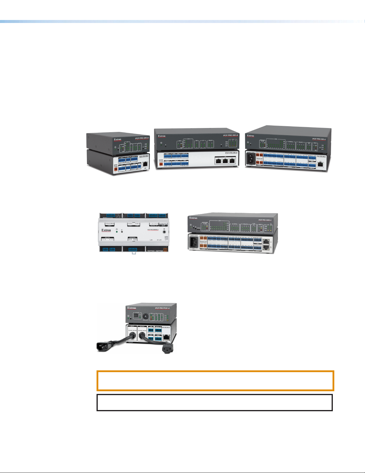
About the IPCPProxiSeries
The IPCPProxiSeries Control Processors integrate Ethernet connection into AV systems to
allow users to remotely control, monitor, and troubleshoot AV equipment, including display
devices, switchers, source devices, and various other items such as
lights, a projector lift, or a screen motor. They can be used in a distributed control system
environment or as stand-alone control processors. Some models (such as the IPCPPro550xi
and IPCPPro555Qxi) also have the ability to power devices that accept 12VDC.
This series of control processors offers increased deployment speed, improved runtime
performance, support for the Extron ControlScript sandbox, and increased memory to
accommodate more complex projects.
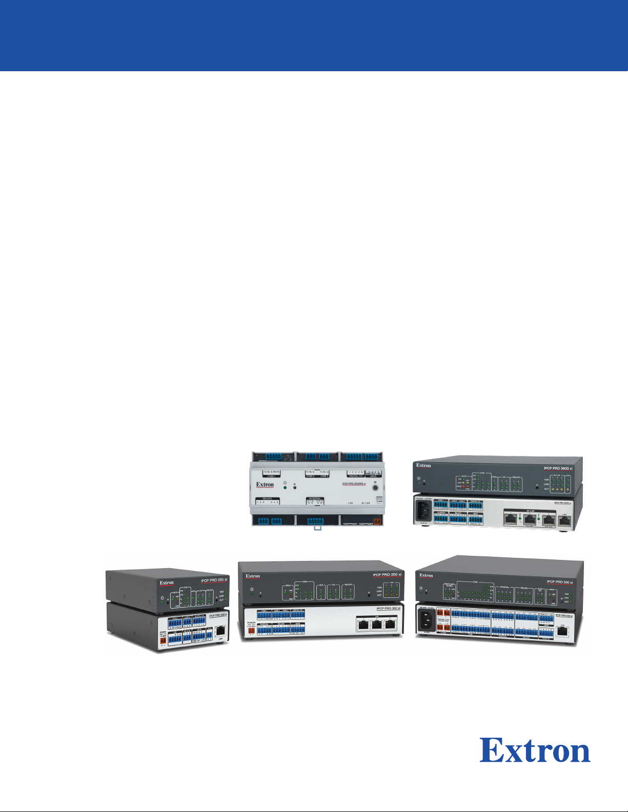
Figure 1. IPCPPro250xi (Left), IPCPPro350xi (Center), IPCPPro550xi (Right)
IPCPProxi Control Processors with AV LAN provide a secure network dedicated for the
connection and isolation of AV devices.
Figure 2. Models with Dedicated AV LAN Ports:
IPCPPro355DRQxi (Left), IPCPPro555Qxi (Right)
The IPCPProPCS1xi provides a controlled AC power output which can be monitored and
controlled, along with a circuit breaker that provides overcurrent protection to the connected
device.
Figure 3. IPCPProPCS1xi
CAUTION: This product is intended for indoor use only.
ATTENTION : Ce produit est exclusivement adapté à un usage intérieur.
NOTE: The IPCPProPCS1xi is intended to be used with Extron Electronics products
only.
An IPCPProxiSeries control processor is the centerpiece of a control system that features
Extron TouchLinkPro Touchpanels, or Extron eBUS button panels connected to the eBUS
port on the control processor. The IPCP supports multiple TouchLinkPro touchpanels over
a standard Ethernet network. The touchpanels provide a convenient interface for controlling
IPCP Pro Q xi and xi Series • Introduction 2
Page 11

Features
the IPCP, which, in turn, controls the other system components. Another option is to use a
third-party device such as a touchpanel or tablet in conjunction with Extron LinkLicense.
NOTE: GUI Designer software is used to design the user interface layout of any Extron
TouchLinkPro touchpanel or third-party touch interface that is used with the IPCP.
Use the Extron Toolbelt software to discover and manage the IPCPProxi control processor
and other Extron control products. Configure the control processor using GCProfessional
or GC Plus, or program it using Global Scripter (GS). Once you have set up how you want it
to work (set up IP addresses and functions, assigned drivers to ports, configured relays and
digital input or output), that information is saved to a project configuration file that is built
and uploaded into the IPCP and to any optional TouchLinkPro touchpanels.
The IPCPProxiSeries integrates seamlessly with Extron GlobalViewer Enterprise software
and Extron Control for Web, iOS, and Android for remote control applications.
General features
Faster microprocessors and expanded memory — These models offer increased
project upload speeds, faster runtime performance, and the ability to create more
sophisticated projects.
• IPCPProxi models — 1 GB of RAM, 8 GB of flash memory
• IPCPProQxi models (models with AV LAN ports) — 2 GB of RAM, 8 GB of flash
memory, quad-core processor
Flexible options for device control — The IPCP offers RS-232 and infrared (IR) control,
TCP/Ethernet control and monitoring, relays, and either digital I/O (digital input or digital
output) or flex I/O (analog input, digital input, or digital output) controls.
• Any IPCPProxi control processor with an IR receiver port can learn IR signals from
remote controls to communicate with sources such as DVD players. Users can create
their own IR device drivers or go to the Extron website (www.extron.com) to obtain
drivers.
• All models include an Extron eBUS port, which allows a variety of eBUS devices (such
as button panels) and accessories (including power and signal hubs) to be connected
to a single control processor. eBUS button panels are automatically recognized by the
control processor and can be added or removed at any time.
• Some models also offer contact input ports, independently switched 12VDC power
output, or a port for volume control of an Extron audio amplifier.
• The IPCPProPCS1xi includes one switched AC power output port for power control
of a connected device.
Several mounting options
• The IPCPPro 355DRQ xi can be mounted to a standard 35mm × 7.5mm DIN rail.
• All other models are housed in a standard 1U high enclosure which is easily rack
mounted or can be installed in or under furniture with an optional mounting kit.
Universal power system compatibility
• The IPCPPro360Q xi, IPCPPro550xi, and IPCPPro555Q xi include an internal
power supply that accepts 100-240 VAC, 50-60 Hz input.
• Other models include a 12VDC external power supply that accepts 100-240 VAC,
50-60 Hz input.
• Some models offer PoE+ output on the LAN or AVLAN ports.
IPCP Pro Q xi and xi Series • Introduction 3
Page 12

Network and configuration features
• Global compatibility — The IPCP uses industry standard Ethernet communication
protocols, including DHCP, DNS, HTTP (redirect), HTTPS, ICMP, IEEE 802.1X, NTP,
SFTP, SMTP, SNMP, SSH, TCP/IP, and UDP/IP.
• Network switch — The IPCPPro350xi and IPCPPro360Qxi include an
unmanaged threeport switch that supports 10Base-T up to gigabit (1000Base-T)
Ethernet communication. Connect any one of these ports to the network for
communication with the IPCP. Connect the other two ports to devices such as
TouchLink Pro touchpanels and network-controlled AV devices.
• Support for a separate, dedicated AV network (AV LAN) — Some models
(IPCPPro 255Qxi, IPCPPro 355DRQxi, IPCPPro360Qxi, IPCPPro555Qxi) feature
two network interfaces. The interface at the LAN port connects to the corporate
network. The AV LAN network interface is for dedicated control of AV devices so you
can separate AV traffic from your primary corporate network.
• Multi-level password protection — This allows security to be set based on user roles.
• Embedded web pages — The IPCP embedded web pages include online
diagnostics and monitoring of basic features.
• If the unit is configured to work with Extron Control, you can access the virtual user
interfaces from a link in the embedded web page.
• The AC power output port of the IPCPProPCS1xi can also be managed (turned
on or off) via its embedded web page.
• Remote equipment management — The IP Link Pro connection allows you
to remotely manage, monitor, and control several Ethernet-enabled products such
as projectors, cameras, video conferencing equipment, switchers, and other AV
equipment. The IPCP provides support for the following:
• TCP, UDP, and HTTP connections
• Password protection using secure communication
• Up to 32 (GCProfessional) or 8 (GCPlus) Ethernet devices at a time depending on
the configuration mode
• Connection via IP address or host name
• System asset management — The configured system and control processor allow
you to control, monitor, and schedule various functions of devices in the system.
• E-mail notification — The IPCP can be set up to send e-mail notifications, such as a
notice that a projector has been disconnected or the projector lamp has been used for
a designated number of hours.
• Additional security features — Each control processor can use the included Secure
Sockets Layer (SSL) certificate or a user-supplied, customized security certificate (see
Secure Sockets Layer (SSL) Certificates on page61. IEEE 802.1X Authentication
is also supported in our devices once enabled. For details see IEEE 802.1X
Certificates on page62. These control processors also comply with NIAP security
standards.
• Support for the Extron ControlScript sandbox environment.
IPCP Pro Q xi and xi Series • Introduction 4
Page 13

Feature Summary Table
The following table provides a summary of models and major features.
Features
Ports
Model
IPCPPro250xi
IPCPPro255Qxi
IPCPProPCS1xi
IPCPPro350 xi
IPCPPro355DRQxi
IPCPPro360Qxi
IPCPPro550xi
IPCPPro555Qxi
Power
Mounting
Supply
Rack External — — 1 1 1 2 — 4 1 1 1 — —
Rack External — — 1 1 1 2 — 4 1 1 1 1 —
Switched
12VDC Out
Switched
AC Out
3-pole COM
5-pole COM
IR/Serial
Relay
Flex I/O
Digital I/O
eBUS
Volume
Control
LAN
AVLAN
PoE+
Rack Internal — 1 1 — 1 — — 3 1 — 1 — — —
Rack External — — 2 1 2 4 — 4 1 — 3 — —
DIN
External — — 2 1 2 4 — 4 1 — 1 1 —
rail
Rack Internal — — 2 1 2 4 — 4 1 — 1 3 2 AVLAN
ports
Rack Internal 4 — 6 2 8 8 4 — 1 — 1 — —
Rack Internal 4 — 6 2 8 8 4 — 1 — 1 1 —
IR Learning
IPCP Pro Q xi and xi Series • Introduction 5
Page 14

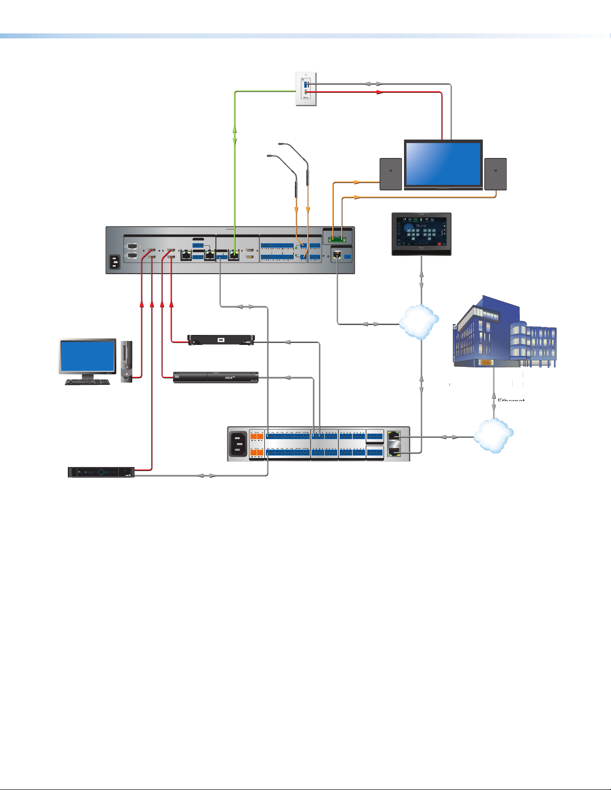
Application Diagrams
TLP Pro 1520MG
The following figures show examples of types of devices that can be connected to some of
the ports on the IPCPProxiSeries control processors.
Microphones
Laptop
POWER
AUDIO
12V
0.7A MAX
HDMI
SIG LINK
INPUTS OVER DTP
DTP OUT
IR
RS-232
TxRx Tx RxG
Audio
Extron
DTP HDMI 230 Tx
Transmitter
INPUTS
OVER DTP
RS-232 IR
AUDIO
TxRx GTx Rx
Extron
DTP HDMI 230 D Tx
Transmitter
Blu-ray Player
Extron FF 220T
Plenum 2' x 2' Flat Field
Ceiling Speakers
Flat Panel Display
Audio
1
CONFIGURABLE
100-240V ~ -- A MAX
2
Component HDMI HDMI
Tuner
PUSH PUSH
POWER GUIDE MENU RES 480480p 720p1080i1080p
DIRECTV
50/60 Hz
DIRECTV HD
SELECT
Flat Panel Display
TouchLink
for iPad
Wireless
Ethernet
RS-232RS-232
2 1 2
TxRx G TxRxG TxRx G TxRx G S G S G S G S G
RTSCTS
8
4 5 6
TxRx G TxRxG TxRx G TxRx G
RTSCTS
S G S G S G S G
IR
5 6
Extron
IPCP Pro 550 xi
IP Link Pro
Control Processor
CATx Cable
up to 230' (70 m)
INPUTS
5
3
7
SIG LINK
HDMI
HDMI
6
4
DTP IN
HDMI HDMI
IN1608 MA
OVER DTP
RS-232 IR
C
TxRx Tx RxG
8
SIG LINK
SIG LINK
OVER DTP
OVER DTP
RS-232 IR
RS-232 IR
TxRx TxRxG
DTP IN
TxRx TxRxG
OUTPUTS
L L1 R R
A
HDMI
L 2
L 4
R
B
DTP OUT
AUDIO INPUTS OUTPUTS
3
L 5 R
+48V
MIC/LINE
L 6
R
R
2
+48V
Extron
IN1608 MA
Scaling
Presentation
Switcher
AMPLIFIED OUTPUT
70V - 100W
1 2
CLASS 2 WIRING
REMOTE
LAN
VARIABLE
RESET
RS-232
L R
TxRx
G
Audio Audio
Media Player
1
RS-232
PC
RS-232
100-240V ~ 50-60Hz
1.2A MAX
1 1 2 3 7
SWITCHED 12 VDC
40W MAX TOTAL
3 4
Integrated 100 W amplier provides audio coverage for a 50' x 40' (15.2 m x 12.2 m) room.
Extron
15" Wall Mount
TouchLink Pro
Touchpanel
Ethernet/
Power
Power
Injector
Ethernet
Ethernet
3 4
1 2
3 4
7 8
5 6
7 8 321 4 G
TCP/IP
Network
IPCP PRO 550 xi
PWR OUT = 12W
+V+S -S G
eBUS
FLEX I/ORELAYSIR/SERIALCOM12 VDC
00-05-A6-XX-XX-XX
MAC: 00-05-A6-XX-XX-XX
S/N: ####### E######
LAN
Figure 4. An IPCPPro550xi Application
IPCP Pro Q xi and xi Series • Introduction 6
Page 15
RS-232
IP Link Pro Control Processor
Extron
d
i
SC
CE
100-240V ~ 1.5 A MAX
1
2
CONFIGURABLE
HDMI
HDMI
5
6
7
8
1C
RS-232 IR
RS-232 IR
Tx Rx Tx RxG
Tx Rx Tx RxG
Tx Rx Tx RxG
HDMI
1A
1B
3
4
INPUTS
OUTPUTS
Tx Rx
RS-232
G
RESET
AUDIO INPUTS
OUTPUTS
REMOTE
L L1 R R
L 2
R
3
L 4
R
L 5 R
+48V
+48V
1 2
L R
VARIABLE
IN1608 xi IPCP MA 70
2
MIC/LINE
L 6
R
SIG LINK
DTP IN
SIG LINK
DTP IN
SIG LINK
DTP OUT
50/60 Hz
RS-232 IR
OVER DTP
OVER DTP
AMPLIFIED OUTPUT
DTP
HDBT
Tx Rx
RTS CTSGTx Rx G Tx Rx G
LAN
AV LAN 2 AV LAN 3
AV LAN 1
R
1 2 3 4 G
DIGITAL I/OCOM 3COM 2COM 1
S SG G
1122C 3 4 C
-S G+S+V
PWR OUT = 6W
IR/SERIAL eBUSRELAYS
70V - 100W
CLASS 2 WIRING
POWER
12V
2
--A MAX
Rx GTx RxTxG
RS-232 IR
RxTx
1
RGB, Y, R-Y, B-Y HDMI HDMI
SIG LINK
DTP OUT
AUDIO
CONTACT
RS-232TALLY
3
12 3 G 1 2 3+V
RESET
INPUTS
OVER DTP REMOTE
LAN
3
21
4
321
WiFi
12 3 4
Extron
Cable Cubby
ETV
POWER STANDBY
Monday, December 16, 2013 7:04 AM
Menu DeleteKey
2
ABC3DEF
6
MNO5JKL4GHI
9
WXYZ8TUV
0
7
PQRS
1
800.633.9876
End
Call
Call
Enter
Full
Screen
Camera Display Presets
Privacy
Near
End
Zoom
In
Zoom
Out
Far
End
Contacts
Name +-
Sources
Andrew
Video Window
Beth
Charlie
David
Ervin
Frank
Greg
Harold
Kevin
Mike
Andrew
(800) 633 - 9876
1 2 3
Help
System
Off
Display
Room
Control
Off
Mute
Screen
Lighting
December 15, 2013 - 7:58 AM
Audio
Control
Volume
Mute
Tuner
1 2 3
VCRLaptop PC DVD
Doc
Cam
Tuner
On
Channel
Last
Presets
More
Presets
321
654
987
Enter
0
AV LA N
Corporate
LAN
Extron
TLP Pro 1220TG
12" Tabletop
TouchLink Pro
Touchpanel
Audio
VGA
VGA
HDMI
HDMI
HDMI
DisplayPort
Laptops
Extron
DTP T
USW 333
Transmitter
VC Codec with PIP Output
Microphone
Display
VC Camera
Extron
IN1608 xi IPCP MA 70
Scaling Presentation Switcher
Extron
FF 220T
Plenum 2' x 2' Flat Field
Ceiling Speakers
Ethernet/PoE
Power
Injector
Extron
Cable Cubby 700
Series/2 Cable Access
Enclosure
HDMI HDMI
HDMI
Ethernet Ethernet
Audio
Audio
Ethernet
RS-232 HDMI
Document
Camera
Apple TV
PC in System Rack
VGA
HDMI
IR
IR
HDMI
Audio
Audio
IN1608 SA
Scaling Presentation
Switcher
INPUTS
5
3
HDMI
4
7
SIG LINK
HDMI
6
100-240V ~ -- A MAX
50/60 Hz
1
2
CONFIGURABLE
CATx Cable
up to 230'
(70 m)
OVER DTP
RS-232 IR
Tx Rx Tx RxG
8
SIG LINK
OVER DTP
RS-232 IR
DTP IN
TxRx TxRxG
RS-232 IR
TxRx
OVER DTP
G
TxRx
HDMI OUT
HDMI OUT
HDMI
Extron
DTP R HDMI 4K 231 D
Receiver
Microphones
Display
Extron
SI 26
Audio
Surface
Mount
Speakers
Audio
IN1608 SA
OUTPUTS
C
A
SIG LINK
OVER DTP
RS-232 IR
B
DTP OUT
TxRx TxRxG
DTP IN
AUDIO INPUTS
3
LL1R R
L5R
HDMI
L2
+48V
L4
L6
R
R
R
+48V
AMPLIFIED OUTPUT
2x25W(8Ω)/2x50W(4Ω)
R
L
OUTPUTS
12
CLASS 2 WIRING
REMOTE
VARIABLE
LR
LAN
RESET
RS-232
TxRx
G
MIC/LINE
2
Ethernet
Extron
TLP Pro 1022M
10" Wall Mount
TouchLink Pro
Touchpanel
HDMI HDMI
PC
Tuner
PUSH PUSH
POWERGUIDE MENU RES 480 480p720p 1080i1080p
DIRECTV
SELECT
DIRECTV HD
RS-232
Ethernet
Media Player
1
Blu-ray Player
100-240V ~ 50-60Hz
RS-232
Figure 5. An IPCPPro555Qxi AV LAN Application
1 2
SWITCHED 12 VDC
40W MAX TOTAL
3 4
1.2A MAX
12 VDC
IR
IR
142 3 7
TxRx GTxRxG Tx Rx GTxRxG
TxRx GTxRxG Tx Rx GTxRxG
5 6 8
COM
RTS
CTS
RTSCTS
Extron IPCP Pro 555Q xi
1 2 3 41 2 3 4
SGSG SGSG
5 6 7 8 5 6 7 8
SGSG SGSG
PWR OUT = 12W
+V+S -S G
eBUS
3214G
FLEX I/ORELAYSIR/SERIAL
LAN
AV
LAN
AV
LAN
Ethernet
Ethernet
SCIENCE
IEN
Science
c
il
Bu
t
Building
Ethernet
LAN
IPCP Pro Q xi and xi Series • Introduction 7
Page 16

Device Control
The IPCP must be configured in one of the following ways before it will send commands to a
projector, display, or other device:
• An IR, RS-232, or Ethernet driver file can be downloaded from the Extron website
(www.extron.com/download/index.aspx). The driver is saved to a folder and
commands from the driver are incorporated into the GC configuration file for the control
processor and any touchpanels that will work with it. The configuration file is built and
uploaded to the IPCP via GC.
• If a driver is not already available, RS-232 or Ethernet command strings can be
entered directly from a host computer using GlobalConfigurator. These can then be
incorporated into controls within the GC project.
• IR commands can be entered directly from an IR remote control through IR learning via
IRLearnerPro to create a driver that the unit can use. IR learning is seldom needed,
but it is convenient for adding new or updated commands in the field in the rare cases
when a driver is not already available from Extron.
See the Global Configurator Help File (which comes with the software) for details on setting
up the IPCP and for downloading, programming, or learning device control commands.
About Global Configurator (with GCProfessional and GCPlus Modes)
Global Configurator:
• Loads device drivers for monitoring the status of and controlling devices within the AV
system.
• Uploads GUIDesigner interface layouts to touchpanels and third-party touch interfaces.
• Creates the configuration containing all the settings for the control processor and the
products with which it interacts in the AV system.
• Uploads the configuration to the control processor.
To obtain Extron control product software, you must have an Extron Insider account and
contact an Extron support representative. Extron provides training to our customers on how
to use the software. Access to the features of Global Configurator Professional is available
to users who successfully complete Extron Control Professional Certification.
About Global Scripter
For those who prefer to program control systems rather than configure them, Extron offers
GlobalScripter as an alternative to Global Configurator. Global Scripter is an integrated
programming development environment for Extron IPLinkPro, TouchLinkPro, and eBUS
products. It uses the object-oriented Python programming language and a custom Python
library called ControlScript. Global Scripter includes the ControlScript API as well as all of
the tools for developing control system programs, such as file management, code editing,
debugging and diagnostic tools. More information is available at http://www.extron.com/
technology/landing/programming/.
IPCP Pro Q xi and xi Series • Introduction 8
Page 17

About Additional Software Used to Deploy Configurations from LAN to
Products on an AVLAN
Extron Product Configuration Software (PCS), XTPConfigurator, and DSPConfigurator
provide the ability to configure devices connected to the AV LAN of an IPCPPro control
processor.
PCS can do the following:
• Discover and display the supported IPCP devices
• Securely connect through the IPCP and display a list of devices connected to its
AVLAN
• Configure various devices found on the AVLAN
Each of these applications can perform additional functions that vary by software type, such
as performing firmware updates or configuration restoration for connected products on the
AVLAN.
PC System Requirements
To find the minimum hardware and software requirements for the PC you use to configure
the IPCPProxiSeries:
• Visit the Download page (www.extron.com/download/index.aspx) on the Extron
website and navigate to the web page for the specific software package (such as
Global Configurator and GUI Designer). Minimum PC hardware and software system
requirements are listed in the description section. In some cases, minimum device
firmware version requirements are also listed there.
• If system requirements are not listed on the software package web page, contact an
Extron support representative.
IPCP Pro Q xi and xi Series • Introduction 9
Page 18

Hardware Features and Installation
This section covers the following material:
• Setup Checklist: How to Proceed With Installation — A checklist of tasks to guide
you through installation
•
Network Communication Setup — A flowchart guide to network settings configuration
• Front Panel Features — Locations and some descriptions of items on the front panel
• Mounting the IPCPPro xi Series — Brief guidelines for mounting
• Ports, Addressing, and Connections — Locations, descriptions, and cabling notes
for rear panel features and corresponding front panel indications
• Resetting the Unit — Information about the available reset modes and how to reset
the IPCP
Pay careful attention to the order and types of setup tasks. Follow the setup checklist in this
guide or in the setup guide and keep it with you for reference throughout the installation and
configuration process.
Setup Checklist: How to Proceed With Installation
Get Ready
Familiarize yourself with the features of the control processor (see Front Panel
Features on page14 and Ports, Addressing, and Connections on page19)
and of any TouchLinkPro touchpanels or button panels that will be part of the system.
Download and install the latest version of the following:
Toolbelt software — for discovering the control processor and other control
products on the network, for managing core settings, and for upgrading firmware
when needed.
Global Configurator (GC) software — for configuring the control system.
Global Scripter software — for programming the control processor (as an
alternative to GC)
PCS Product Configuration Software version 4.5 or higher — for setting the IP
addressfor any IPCPProQxi model with AV LAN ports if the ports are currently set
to the default IP addresses
GUI Designer software — for designing layouts for Extron TouchLinkPro
touchpanels and third-party touch interfaces
IPLinkPro device drivers — for use with GC, to make control of other devices
possible
IR Learner Pro software — for use with models that have IR receiver ports, to
create your own IR drivers using the remote control of an AV device, if drivers are
not already available from Extron
All are avail able from www.extron.com (see Locating Software, Firmware, and
Driver Files on the Extron Website on page54).
IPCP Pro Q xi and xi Series • Hardware Features and Installation 10
Page 19

Obtain network information for the unit from the network administrator. You need the
following details for each IPLinkPro device:
DHCP setting (on or off) Gateway IP address
Device (IPCPPro, TouchLinkPro, IPLPro) LAN IPaddress Username
AVLAN IPaddress (for models with AVLAN)
Subnet mask
Write down the MAC address of each network interface on each IPLinkPro device to
be used.
Obtain model names and setup information for devices the IPCP will control.
Each control processor comes with a factory-installed Secure Sockets Layer (SSL)
security certificate. If you intend to install a different SSL certificate, contact your IT
department to obtain the certificate or for instructions on how to obtain one (see
Secure Sockets Layer (SSL) Certificates on page61 for requirements and
guidelines regarding SSL certificates).
For systems that will use IEEE 802.1X security, obtain a PEM-encoded security
certificate and private key (see IEEE 802.1X Certificates on page62) from your IT
department.
Mount and Cable All Devices
Mount the unit to a rack or furniture (see Mounting the IPCPPro xi Series on
page17).
Cable devices to the control processor (see Ports, Addressing, and Connections
starting on page19).
Connect power cords and power on all the devices.
Passwords
Set Up the Control Processor, Touchpanels, and Network Button Panels for Network Communication
For models without AVLAN ports: Connect the PC that you will use for setup, the
LAN port of the control processor, and the touchpanels or network button panels to the
same Ethernet network. For control processor LAN connections, see LAN (Ethernet)
connectors and LEDs on page29.
For models with AVLAN ports: Connect the PC that you will use for setup, the
control processor, and the touchpanels or network button panels to the Ethernet
network. For control processor AVLAN connections, see AV LAN connectors and
LEDs on page29.
Start Toolbelt and use it to set the IP address or addresses, subnet, gateway
IP address, DHCP status, and related settings (see the flowchart in Network
Communication Setup on page13).
NOTES:
• When setting up DHCP during network configuration or if using a host name
instead of an IP address, the user must enter a qualified host name
(Username.HostName.Domain). For example: somename.extron.com.
• A dedicated AV LAN safeguards AV systems from outside intrusion or
interference by separating device control and other network traffic from a
corporate or campus network. To ensure that the control processor LAN and
AV LAN connections (ports) are connected to separate networks, the LAN and
AV LAN IP address schemes must be on different subnetworks.
IPCP Pro Q xi and xi Series • Hardware Features and Installation 11
Page 20

Configure or Program the Control Processor, Touchpanels, and
Network Button Panels
If TouchLinkPro touchpanels are part of the system, start and use GUIDesigner
to design, save, and build the graphical user interface (GUI) layout for the
touchpanels (see the GUIDesigner Help File for instructions).
NOTE: To redeem (activate) a LinkLicense, go to www.extron.com/llredeem and
follow the online instructions.
A LinkLicense unlocks features that add convenience, expand system options,
and enhance the capabilities of your Extron products. For IPCPProQxi and xi
systems, a LinkLicense allows you to use a mobile device or computer as the
primary control interface in an Extron control system where a TouchLink Pro
touchpanel may not be present.
If using GC, create a new GCProfessional or GCPlus project and configure the
control processor and other IP Link Pro devices. The configuration tells the control
processor:
• How its ports function • What to monitor
• How to control other products • When to do things
• Which touchpanels to interact with • Whom to notify, how, and under what
circumstances
Configure ports on the control processor:
Select device drivers and link them to each serial, IR/serial, or Ethernet port.
Select settings (serial protocol, relay behavior, digital I/O or flex I/O settings, AC
output settings) as needed.
Add eBUS devices and set them up:
Ensure that the hardware address (eBUS ID) set on each device is distinct and
matches the address used in the configuration.
Assign button functions as desired.
Add Network Button Panels (NBPs) and set them up. Assign button functions as
desired.
Set up monitors, schedules, macros, and local variables.
Add touchpanels and set them up:
Upload the GUI configuration to the Global Configurator project.
Assign any appropriate functions, monitors, or schedules to the touchpanels
and their buttons.
If not using GC Professional or GC Plus, use Global Scripter to program the
control system as desired.
Program ports on the control processor:
Program each serial, IR/serial, or Ethernet port.
Program relay behavior, digital I/O, flex I/O, and AC output settings as needed.
Add eBUS devices and set them up:
Ensure that the hardware address set on each device is distinct and matches
the addresses programmed for them in the IPCP.
Program button functions as desired.
Add Network Button Panels (NBPs) and set them up. Assign button functions as
desired.
IPCP Pro Q xi and xi Series • Hardware Features and Installation 12
Page 21
Add touchpanels and set them up:
Upload the GUI configuration to the Global Scripter project.
Program functions, monitors, or schedules to the touchpanels and their
buttons.
Save the project.
Build and upload the system configuration to the control processor and other system
devices.
Test and Troubleshoot
Test the system (see the Troubleshooting section starting on page57 for an outline
of items to check during system troubleshooting).
Make adjustments to wiring or configuration as needed.
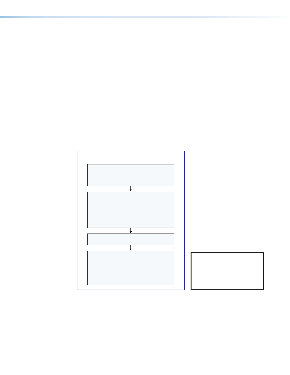
Network Communication Setup
Network setup is essential prior to configuration. Use the flowchart as a general guide to
setting up the control processor for network use.
Network Communication Setup
Connect the PC and the LAN port or AV LAN
port of the control processor to
the same network.
Apply power to all devices.
Open the Toolbelt software from within
Global Congurator (GC Professional or
GC Plus mode) or as the stand-alone
Toolbelt displays a list of all Extron control
devices connected to the network.
Using the MAC address, locate the desired
control processor in the list and select it.
(LAN, or LAN and AV LAN), use the Set IP
Toolbelt
feature to enter the IP address and
subnet address, then congure other
application.
Start Device Discovery.
For each network interface
feature in Toolbelt or use the
Manage > Network Settings tab
network settings as needed.
Figure 6. Network Setup
NOTE: If using 802.1X security,
see the Extron 802.1X
Technology Reference Guide
and the Toolbelt Help file for
additional details on system
setup.
IPCP Pro Q xi and xi Series • Hardware Features and Installation 13
Page 22
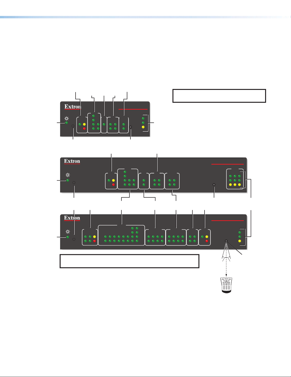
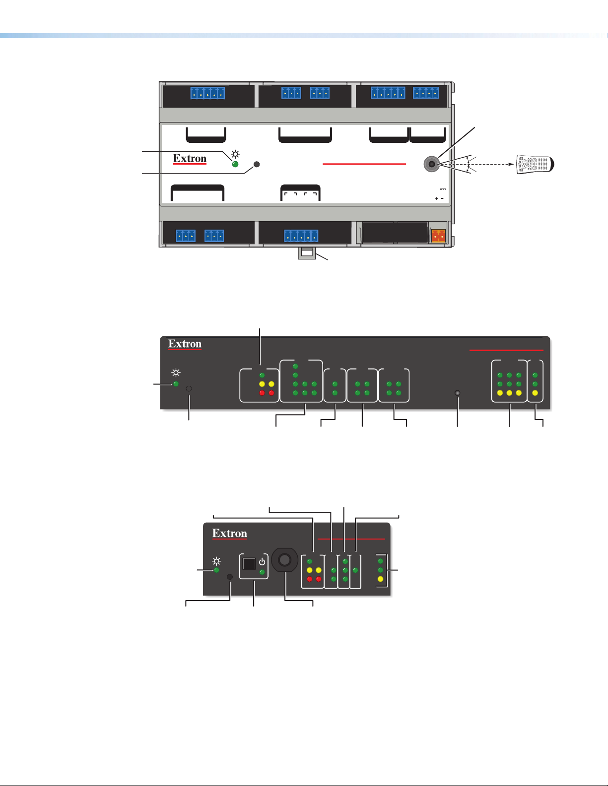
Front Panel Features
COM
IR/
eBUS
Relay
Digital
Power
Power
Power
This section shows front panel features and their locations. The quantity and location
of ports and corresponding front panel LEDs differ among IPCP models. However, the
functions of each type of port and their LEDs are identical for all models. Aside from a few
features of the IPCPProPCS1, most of the features and LED indications are described and
shown in the Ports, Addressing, and Connections section starting on page19 paired
with the descriptions of the corresponding ports.
LEDs
(Serial)
LEDs
Serial
LEDs
I/O
LEDs
LEDs
NOTE: For reset mode information, see
Resetting the Unit on page49.
LED
LED
LED
Reset Button
(recessed)
Reset
Button
(recessed)
R
R
R
COM
RTS
eBUS
S
LIMIT
OVER
CTS
Tx
Rx
1
I/O RELAYS
IR/S
2
314
eBUS LEDs
Switched
12 VDC
eBUS
S
LIMIT
OVER
COM (Serial)
LEDs
SWITCHED
12 VDC
21
LIMIT
Tx
Rx
43 12345678
OVER
IPCP PRO 250 xi
2
1000
1
LINK
IR
2
IR Receiver
COM
RTS
CTS
Tx
Rx
LEDs
COM
LAN/
Network
ACT
LEDs
Digital I/O LEDs
I/O
IR/S
3142314
2231
IR/Serial
LEDs
RTS
IR/SERIAL RELAYS FLEX
CTS
2134
Tx
Rx
5 678
See the Software-based
Configuration and Control section
starting on page52 and the
GlobalConfigurator Help File and
Toolbelt Help File for information about
Global Configurator and Toolbelt,
which you must use to set up the unit.
RELAYS
21
LEDs
Flex I/O
LEDs
Relay
5 678213 4
I/O
2134
IPCP PRO 350 xi
1000
LINK
IR
ACT
IR Receiver
eBUS LEDs
IPCP PRO 550 xi
eBUS
S LIMIT
OVER
IR
LAN
12
1000
LINK
ACT
3
LAN/
Network
LEDs
NOTE: Numbers adjacent to LEDs correspond to the like-numbered
rear panel ports.
15˚ 15˚
2–12"
(4–30 cm)
1 2 3
4 5 6
7 809
Figure 7. Front Panels: IPCPProxi Series Rack Mountable Models Without AV LAN
IPCP Pro Q xi and xi Series • Hardware Features and Installation 14
IR Receiver
IR Learning
Angle and
Distance
Page 23
IPCP Pro 355DRQ xi Front Panel
Power
LEDs
LEDs
eBUS LEDs
Receiver
LEDs
LEDs
LEDs
LEDs
Power
COM (Serial) LEDs
Digital
I/O LEDs
Reset Button
eBUS
Network
IR/
Serial
LIMIT
eBUS
OVER
Rx
CTS
RTS
Tx
ERROR
LINK
BUSY
COM
I/O
RELAYS
IR/S
12 121
COM
(Serial)
LEDs
IR/
Serial
LEDs
eBUS
LEDs
Relay
LEDs
Digital
I/O
LEDs
IPCP Pro xi AV LAN Embedded Control Processor
(within another device)
LED
Reset
Button
(recessed)
LED
GTx Rx GTx Rx
COM 2COM 3
IR/SERIAL
1SG2
SG
IPCP PRO 355DRQ xi
2143CC
COM 1
RELAYS
GTx Rx
RTSCTS
R
Mounting Clip
Figure 8. IPCPPro355DRQxi Front Panel
COM
LIMIT
OVER
RTS
CTS
Tx
Rx
IR/S
2231
eBUS
R
LINK
BUSY
ERROR
1234G
DIGITAL I/O
LAN
RELAYS
I/O
3142314
21
+V +S -S G
PWR OUT = 6W
eBUS
AV LAN
IR
POWER
12V
1A MAX
IR Receiver
IR Learning Angle
and Distance
15˚
15˚
2–12"
(4–30 cm)
IPCP PRO 360Q xi
AV LAN
12
1000
LINK
IR
ACT
9
0
1 2 3
4 5 6
7 8
LAN
3
Figure 9. IPCPPro360Qxi Front Panel
Power
(recessed)
Figure 10. IPCPProPCS1xi Front Panel
Reset
Button
(recessed)
LED
LEDs
R
AC Power Button
and LED
COM (Serial)
IR/Serial
Digital I/O
Relay
IR
AV LAN
LED
IPCP PRO PCS1 xi
O
R
POWER
T
10
S
S
E
R
P
BREAKER
E
S
E
T
L
B
E
eBUS
LIMIT
OVER
COM
Tx
Rx
I/O IR/S
1
2
3
1000
LINK
ACT
LAN/
LEDs
Circuit
Breaker
IPCP Pro Q xi and xi Series • Hardware Features and Installation 15
LAN
Page 24

IPCP Pro PCS1 xi-Specific Front Panel Features
POWER
BREAKER
Power button (switch) and LED
The front panel power button (switch) provides a convenient way to manually
turn switched AC power output on or off for the rear panel AC power output
cable on the IPCPProPCS1xi.
NOTE: The button is not a safety disconnect device. In case of an emergency, disconnect
AC power from the power input (appliance inlet) of the connected equipment.
The IPCPProPCS1xi can be configured (using Global Configurator or Global Scripter)
to monitor the power output condition and to alert users in the event of a power fault
interruption. The IPCPProPCS1xi can be set up to monitor the circuit breaker and also the
current load at the switched AC power output port.
NOTE: The power output state setting persists after and is retained during a power cycle.
The AC power LED on the IPCPProPCS1xi lights to indicate the power output state as follows:
Lit green: Power output is enabled.
Off (dark): Power output is disabled.
Lit red: A fault condition is detected, and power output is disabled.
Front panel lockout (executive mode)
To prevent unauthorized use, the power button can be locked (disabled) via a front panel
lockout mode (executive mode) that can be enabled or disabled by one of two methods:
• Using software, as part of the configuration or when programming actions, monitors, or
schedules
• Pressing and holding down the Power button for 3 seconds
The power LED blinks three times to indicate the lockout mode has been enabled or disabled.
When the front panel is locked, if the Power button is pressed, the power LED blinks three
times to indicate that the button is locked, and the unit does not change power states as a
result of the button press.
NOTE: The executive mode state (on or off) persists after and is retained during a power
cycle.
Circuit breaker
The front panel features a 10A rated circuit breaker. When a fault condition
occurs, the breaker is triggered, which stops power output. This condition can
be monitored and the system can be configured (using available commands) to
send an alert e-mail or perform some other action. After you correct the cause
of the overcurrent condition, press the Breaker button to manually reset the circuit breaker.
NOTES:
• The circuit breaker and the Reset button are not affected by front panel lockout
(executive mode) settings.
• The embedded web page for the unit displays the state of the circuit breaker and
the value of the combined current load.
IR Learning Receiver
In most cases, Extron has already produced a driver file for controlling the projector, display,
or source device you plan to use. If a device driver file is not available, you can create your
own using Extron IR Learner Pro software, the remote control of the projector or display,
and the IR learning receiver sensor on the IPCPs.
NOTE: The PCPProPCS1xi does not have an IR learning sensor.
O
R
T
E
10
10
S
S
E
R
P
IPCP Pro Q xi and xi Series • Hardware Features and Installation 16
S
E
T
Page 25

The IR learning receiver accepts infrared signals from 30 kHz to 300 KHz. The IR remote
control must be pointed directly at the receiver for best results. The front panel diagrams
(see the bottom of figure 7 on page14 and the right side of figure 8 on page15)
indicate the best distances and angles (15 degrees off axis from the receiver) at which to
hold the remote control.
Reset Features
Reset button and LED — Pressing this recessed button causes various product settings
to be reset to the factory defaults. The green power LED blinks depending on the selected
reset mode (see Resetting the Unit on page49 and the reset modes table starting on
page49 for details).
Mounting the IPCPProxiSeries
Mounting Options
Rack and furniture mounting
Optional 1U high rack shelves and a variety of rack mounting bracket kits and furniture
mounting kits are available for use with most of the IPCPProxi models. Visit the productspecific page on the Extron website (www.extron.com) for a list of compatible accessories
for mounting your control processor or call a support representative to find out which kit
to order for your installation. Read the instructions that are included with the rack shelf or
mounting kit for installation procedures and see the UL rack mounting guidelines below for
safe installation.
DIN rail mounting
The IPCPPro355DRQxi mounts to a standard 35mm “top hat” DIN rail (EN50022,
IEC60715, USTS35) system that uses rails that are 35 mm high x 7.5 mm deep. Rear
Panel Features of DIN Rail Models on page18 provides a way to identify mounting
features. Mounting instructions are available in Mounting an IPCP DIN Rail Unit to a DIN
Rail on page18.
UL Rack Mounting Guidelines
The following Underwriters Laboratories (UL) guidelines pertain to the safe installation of
IPCPProxiSeries control processors in a rack.
1. Elevated operating ambient temperature — If installed in a closed or multi-unit
rack assembly, the operating ambient temperature of the rack environment may be
greater than room ambient temperature. Therefore, install the IPCP in an environment
compatible with the maximum ambient temperature (Tma = +122 °F, +50 °C) specified
by Extron.
2. Reduced air flow — Install the equipment in a rack so that the amount of air flow
required for safe operation of the equipment is not compromised.
3. Mechanical loading — Mount the equipment in the rack so that a hazardous
condition is not achieved due to uneven mechanical loading.
4. Circuit overloading — Connect the equipment to the supply circuit and consider the
effect that circuit overloading might have on overcurrent protection and supply wiring.
Appropriate consideration of equipment nameplate ratings should be used when
addressing this concern.
5. Reliable earthing (grounding) — Maintain reliable grounding of rack-mounted
equipment. Pay particular attention to supply connections other than direct connections
to the branch circuit (such as use of power strips).
IPCP Pro Q xi and xi Series • Hardware Features and Installation 17
Page 26

Rear Panel Features of the DIN Rail Model
Clip
Clip
12
Mounting
Slot
Rear ViewSide View
Mounting
Figure 11. IPCPPro355DRQxi Rear Panel Features
Mounting an IPCP DIN Rail Unit to a DIN Rail
To fasten the IPCPPro355DRQxi to a DIN rail:
Mounting
Side View
3
Figure 12. Mounting the IPCP Pro 355DRQxi to a DIN Rail
1. Place the unit in front of the rail, with the top rear against the wall or furniture (see
figure 12, 1).
2. Slide the IPCPProxi down so that the upper part of the mounting slot seats onto the
top of the DIN rail (2).
3. Tilt the base of the IPCPProxi toward the rail and press until the unit snaps into place
on the rail (3).
Figure 13 on the next page shows how the IPCPProxi looks after it is mounted, before
cables are connected.
IPCP Pro Q xi and xi Series • Hardware Features and Installation 18
Page 27

GTx Rx
RTSCTS
COM 1
GTx Rx GTx
RELAYS
21 43
COM 2 COM 3
R
IR/SERIAL
1
S
G
2
S G
Rx
1 2 3 4 G
IPCP PR O 355DRQ xi
DIGITAL I/O
LAN
AV LAN
+V +S -S G
PWR OUT = 6W
eBUS
IR
POWER
12V
1A MAX
CC
Figure 13. The IPCPPro355DRQxi Mounted on a DIN Rail, Before Cabling
Ports, Addressing, and Connections
ATTENTION:
• Installation and service must be performed by experienced personnel.
• L’installation et l’entretien doivent être effectués par du personnel expérimenté.
The quantity of ports and corresponding front panel LEDs differs among IPCP models, but
the functions of each type of port and their LEDs are identical for any model that includes
that type of port.
IPCP Pro Q xi and xi Series • Hardware Features and Installation 19
Page 28

Rear Panels — Rack Mount Models Without AV LAN
EEEEEE
CCCCCCCCBBBBBBBB DDDDDDDD EEEEEEEE HHHHHHHH
JJJJJJ
FFFFFFFF
GGGGGGGG
LLLLLLLL
COM 1
G
RTSCTS
Tx Rx
POWER
VOL
12V
1.0A MAX
AAAAAAAA
IPCP Pro 350 xi
POWER
12V
1.0A MAX
AAAAAAAA
VCG
KKKKKKKK
COM 1
IR/SERIAL
1SG2
FFFFFFFF
E
GTx Rx
IPCP Pro 550 xi
100-240V ~ 50-60Hz
DDDDDDDDEEEEEEEE
COM 2
Tx Rx
RELAYS
RTSCTS
SG
1 1 2 3 7
IIIIIIII
IPCP Pro 250 xi
DIGITAL I/O
G
12 4G
eBUS
-S+V +S G
C12
PWR OUT = 6W
JJJJJJJJ
DDDDDDDDE
COM 2 COM 3
GTx Rx GTx Rx
RELAYS
2143CC
GGGGGGGG
2 1 2
3
IPCP PRO 250 xi
IR/S
SG
FFFFFFFFGGGGGGGG
IIIIIIII
DIGITAL I/O
1234G
eBUS
+V +S -S G
PWR OUT = 6W
J
J
MAC: 00-05-A6-XX-XX-XX
S/N: ####### E######
LAN
LLLLLLLL
MMMMMMMM
3 4
1 2
MMMMMMMM
00-05-A6-XX-XX-XX
MAC: 00-05-A6-XX-XX-XX
S/N: ####### E######
3 4
IPCP PRO 350 xi
LAN
123
LLLLLLLL
JJJJJJJJ
PWR OUT = 12W
IPCP PRO 550 xi
00-05-A6-XX-XX-XX
MAC: 00-05-A6-XX-XX-XX
S/N: ####### E######
IPCP Pro PCS1 xi
1.2A MAX
INPUT
100-240V ~ 10A MAX
50-60Hz
SWITCHED 12 VDC
40W MAX TOTAL
3 4
OUTPUT
100-240V ~ 10A MAX
50-60Hz
TxRx GTxRxG Tx Rx GTxRxG SGSG SGSG
4 5 6
TxRx GTxRxG Tx Rx GTxRxG
IIIIIIII
DDDDDDDD
COM
DIGITAL I/O
1 2 3 G
G
Tx Rx
IR/S
eBUS
-S+V +S G
PWR OUT = 6W
SG
RTSCTS
8
RTSCTS
IPCP PRO PCS1 xi
MAC: 00-05-A6-XX-XX-XX
S/N: ####### E######
LAN
5 6
7 8
SGSG SGSG
MMMMMMMM
5 6
+V +S -S G
eBUS
7 83214G
FLEX I/ORELAYSIR/SERIALCOM12 VDC
Figure 14. IPCPProxi Rack Mount Control Processors (Without AV LAN) Rear Panels
Power input connector (external power supply), page23
A
Power input connector (internal power supply), page24
B
Switched 12 VDC power output ports, page25
c
3-pole COM ports (RS-232 only), page29
D
5-pole COM ports (RS-232/RS-422/RS-485), page28
E
IR/serial output ports, page33
F
Relay ports, page34
G
Flex I/O ports (digital input/output or analog input), page35
H
Digital I/O ports (digital input/output), page41)
I
eBUS ports, page46
J
Volume control port, page48
K
LAN connectors and LEDs (Ethernet), page29
L
MAC address, page32
M
Switched AC power output (attached cable), page26
N
LAN
MMMMMMMM
IPCP Pro Q xi and xi Series • Hardware Features and Installation 20
Page 29

Rear Panels — Rack Mount Models With AV LAN
EEEEEE
I
IPCP Pro 255Q xi
The following panels illustrate a representative set of features for rack mounted
models with AV LAN.
IR/S
SG
FFFFFFFFGGGGGGGG
LLLLLLLLIIIIIIII
MAC: 00-05-A6-XX-XX-XX
S/N: ####### E######
MAC: 00-05-A6-XX-XX-XX
S/N: ####### E######
NNNNNNNN
IIIIIIII
DIGITAL I/O
1 234G
eBUS
+V +S -S G
PWR OUT = 6W
JJJJJJJJ
LAN
AV
LAN
MMMMMMMM
00-05-A6-XX-XX-XX
MAC: 00-05-A6-XX-XX-XX
S/N: ####### E######
12
IPCP AV LAN
AV LAN
PWR
PoE+ OUT PoE+ OUT
PWR
NNNNNNNN
IPCP PRO 360Q xi
00-05-A6-XX-XX-XX
MAC: 00-05-A6-XX-XX-XX
S/N: ####### E######
3
IPCP LAN
LAN
LLLLLLLL
COM 1
G
RTSCTS
Tx Rx
POWER
VOL
12V
0.8A MAX
AAAAAAAA
VCG
KKKKKKKK
PCP Pro 360Q xi
100-240V ~ 1.5A MAX
IR/SERIAL
50-60 Hz
BBBBBBBB
DDDDDDDDEEEEEEEE
DIGITAL I/O
COM 2
3
G
12 4G
Tx Rx
C12
eBUS
-S+V +S G
PWR OUT = 6W
RELAYS
JJJJJJJJ
E
GTx Rx
RTSCTS
SG
COM 2 COM 3
RELAYS
2143CC
COM 1
1SG2
FFFFFFFF GGGGGGGG
DDDDDDDDE
GTx Rx GTx Rx
Figure 15. IPCPProxi Rack Mount Control Processors (with AV LAN) Rear Panels
MMMMMMMM
Power input connector (external power supply), page23
A
Power input connector (internal power supply), page24
B
3-pole COM ports (RS-232 only), page29
D
5-pole COM ports (RS-232/RS-422/RS-485), page28
E
IR/serial output ports, page33
F
Relay ports, page34
G
Digital I/O ports (digital input/output), page41)
I
eBUS ports, page46
J
Volume control port, page48
K
LAN connectors and LEDs (Ethernet), page29
L
MAC address, page32
M
AV LAN connector and LEDs (Ethernet),
N
some with PoE+ and PoE+ LEDs, page29
The following ports are not shown in figure 15 but are available in some AV LAN models such as the
IPCPPro555Qxi.
Switched 12 VDC power output ports, page25
c
Flex I/O ports (digital input/output or analog input),
H
page35
IPCP Pro Q xi and xi Series • Hardware Features and Installation 21
Page 30

I
F
MMMMMM
LLLLLL
NNNNNN
Isometric View
Front Panel — DIN Rail Model
PCP Pro 355DRQ xi
ront Panel
RELAYS
2143CC
GTx Rx
COM 1
RTSCTS
R
DDDDDDDDEEEEEEEE IIIIIIII JJJJJJJJ
GTx Rx GTx Rx
COM 2COM 3
IR/SERIAL
1SG2
SG
Mounting
FFFFFFFFGGGGGGGG
IPCP PRO 355DRQ xi
clip
1234G
DIGITAL I/O
LAN
+V +S -S G
PWR OUT = 6W
eBUS
AV LAN
IR
POWER
12V
1A MAX
M
M
MAC: 00-05-A6-XX-XX-XX
S/N: ####### E######
AAAAAAAA
(On Side)
L
L
Bottom
N
N
Figure 16. IPCPPro355DRQxi Front Panel
Power input connector (external power supply), page23
A
3-pole COM ports (RS-232 only), page29
D
5-pole COM ports (RS-232/RS-422/RS-485), page28
E
IR/serial output ports, page33
F
Relay ports, page34
G
Digital I/O ports (digital input/output), page41)
I
eBUS ports, page46
J
LAN connectors and LEDs (Ethernet), page29
L
MAC address (or addresses), page32
M
AV LAN connector and LEDs (Ethernet),
N
page29
IPCP Pro Q xi and xi Series • Hardware Features and Installation 22
Page 31

Power Connections
Front Panel,
AV LAN
POWER
12V
x.xA MAX
Front/
Rear
Panel,
Rack
Mounted
Models
Bottom
Panel,
DIN Rail
Models
NOTE: The IPCPPro250xi, IPCPPro255Qxi, IPCPPro350xi, and IPCPPro360Qxi
are suitable for use in an environmental air space in accordance with section 300.22.C
of the National Electrical Code, and sections 2-128, 12-010(3) and 12-100 of the
Canadian Electrical Code, part 1, C22.1.
Power input connector (external power supply) — Connect the IPCP to the
A
included 12VDC power supply (part number 28-071-57LF or 28-327-57LF) via this port
(see figure 14, figure 15, and figure 16, A on page20 through page22), then
connect the external power supply to a 100 to 240 VAC power source.
POWER
12V
1A MAX
POWER
12V
1A MAX
3/16"
(5 mm)
Max.
Tie Wrap
Power Input, External Power Supply
• Connect to
included 12 VDC
power supply.
– Return
+12 VDC input
• Front panel LED ( ) blinks during
boot-up and remains lit when the
IPCP is powered and operational.
Ridged
Smooth
To
AC
power
Ground all devices.
External 12 VDC
Power Supply
R
Front Panel,
Rack Mounted
Models
NOTE:
Check the
polarity of the
power supply
before connecting
it to the IPCP.
DIN Rail
Models
R
Figure 17. Connecting an External Power Supply
ATTENTION:
• Always use a power supply supplied or specified by Extron. Use of an
unauthorized power supply voids all regulatory compliance certification and may
cause damage to the supply and the unit.
• Utilisez toujours une source d’alimentation fournie par Extron ou recommandée.
L’utilisation d’une source d’alimentation non autorisée annule toute certification de
conformité réglementaire, et peut endommager la source d’alimentation et l’unité.
• If not provided with a power supply, this product is intended to be supplied by a
UL Listed power source marked “Class 2” or “LPS” and rated output 12VDC,
minimum 1.0A.
• Si le produit n’est pas fourni avec une source d’alimentation, il doit être alimenté
par une source d’alimentation certifiée UL de classe 2 ou LPS, avec une tension
nominale 12Vcc, 1A minimum.
• Unless otherwise stated, the AC/DC adapters are not suitable for use in air
handling spaces or in wall cavities.
• Sauf mention contraire, les adaptateurs CA/CC ne conviennent pas à une
utilisation dans les espaces d’aération ou dans les cavités murales.
• The installation must always be in accordance with the applicable provisions of
National Electrical Code ANSI/NFPA70, article725 and the Canadian Electrical
Code part1, section16. The power supply shall not be permanently fixed to
building structure or similar structure.
• Cette installation doit toujours être conforme aux dispositions applicables
du Code américain de l’électricité (National Electrical Code) ANSI/NFPA 70,
article 725, et du Code canadien de l’électricité, partie1, section16. La source
d’alimentation ne devra pas être fixée de façon permanente à la structure de
bâtiment ou à d’autres structures similaires.
IPCP Pro Q xi and xi Series • Hardware Features and Installation 23
Page 32

Power input connector (internal power supply) — Connect the IPCP to a
Rear Panel
Front Panel
POWER
To a 100 - 240 VAC
B
100 to 240 VAC power source here (see figure 14 on page20 or figure 15 on
page21).
100-240V 50-60Hz
1.2A MAX
Power Input, Internal Power Supply
• Connect to 100 to
240 VAC.
• Front panel LED ( ) blinks
during boot-up and remains lit
when the IPCP receives power.
R
Figure 18. Connecting AC Power to an Internal Power Supply (Most Models)
The IPCPProPCS1xi has an attached AC power input cable.
CAUTION: Always disconnect the product from the wall plug.
ATTENTION : Veillez à toujours déconnecter le produit de la prise murale.
INPUT
100-240V ~ 10A MAX
50-60Hz
Rear Panel
6 inch (152 mm)
IEC Input Cable
OUTPUT
100-240V ~ 10A MAX
50-60Hz
Power Input, Internal Power Supply
• Connect to
100 to 240 VAC.
• Front panel LED ( ) blinks
during boot-up and remains lit
when the IPCP receives power.
R
Front Panel
IEC Power Cord
Figure 19. Connecting an AC Power Source to the IPCPProPCS1xi
power source
(main power)
IPCP Pro Q xi and xi Series • Hardware Features and Installation 24
Page 33

Switched 12 VDC power output ports — These ports (see figure 14, C on
Lights if total power drawn
Lights if total power drawn
C
page20 provide 12VDC output. For the IPCPPro550xi and IPCPProxi 555Qxi,
the four ports provide up to a combined maximum of 40watts. Once configured, each
port can be separately turned on or off. These ports are monitored continuously for total
power usage (draw).
1 2
SWITCHED 12 VDC
40W MAX TOTAL
3 4
Rear
Panel
12 VDC
3/16"
(5 mm)
Max.
Tie Wrap
Switched 12 VDC
Power Output
• Total output for all four ports
combined:
12 VDC, 40 watts (max.)
• Corresponding front panel
green LEDs ( ) light when
power is available at each port.
Front
Panel
SWITCHED
12 VDC
21
43
LIMIT
is 41-46 watts.
OVER
exceeds 47 watts.
Power output shuts off
until the user corrects the
overload.
Figure 20. Switched DC Power Output Ports and LEDs
• When the total power usage exceeds a threshold of 41watts but is still
below 47watts, the IPCP enters the limit mode, during which the yellow front
panel Limit LED lights. If you have configured the unit to do so, the IPCP can issue a
power overcurrent notice.
• If power usage exceeds a second, higher threshold (47watts), the IPCP enters
overcurrent mode. It turns these ports off, and the red front panel OverLED lights.
If the ports are disabled, the user must disconnect or fix the attached devices to
correct the problem. If the power draw is still excessive, the ports remain off.
IPCP Pro Q xi and xi Series • Hardware Features and Installation 25
Page 34

Switched AC power output (attached cable) (IPCPProPCS1xi only) (see figure 14
R
N
on page20) — Provides switched (controlled) AC power output to another device.
CAUTION:
ATTENTION :
• Total length of the power cord including the small pigtail shall not be less than
1.5m or more than 4.5m.
• La longueur totale du câble d’alimentation, cordon compris, ne doit pas être
inférieure à 1,5 m ou supérieure à 4,5m.
• Always use the power cord provided with the unit.
• Veillez à toujours utiliser le câble d’alimentation fourni avec l’unité.
• Should you need to use a different power cord, consult Extron Electronics prior
to using the cord.
• Si vous devez utiliser un autre câble d’alimentation, contactez Extron Electronics
avant d’utiliser ce câble.
INPUT
100-240V ~ 10A MAX
50-60Hz
Rear
Panel
OUTPUT
100-240V ~ 10A MAX
50-60Hz
6 inch (152 mm)
IEC Output Cable
NEMA 5-15R
Adapter
Switched 100-240 VAC, 10 A (Max.) Power Output
• Front panel Power LED appears:
• Lit green ( ) when power output is enabled (unit outputs power)
• Off ( ) when power output is disabled (power output is off)
• Lit red ( ) when a power output overcurrent condition is detected
(the circuit breaker has been tripped) and power output is disabled.
• Front panel Power button controls power output availability.
NOTE: The front panel power switch is not a safety disconnect
device. In case of emergency, disconnect AC power from the
power input (appliance inlet) of the connected equipment.
IEC Power Cord
or
Edison Power Cord
Front
Panel
Power input port
on an AV device
(international)
Power input port
on an AV device
(USA)
Figure 21. Switched AC Power Output Connection (IPCPProPCS1xi Only)
ATTENTION:
• When using the NEMA5-15R receptacle adapter, connect the equipment only
to a nominal 120VAC electrical supply source.
• Lorsque vous utilisez la prise de courant NEMA5-15R, veillez à ne connecter le
dispositif qu’à une source d’alimentation nominale de 120Vca.
POWER
O
R
T
E
10
S
E
S
T
S
E
R
P
BREAKER
Circuit Breaker
(power output
overcurrent
protection)
NOTES:
• Within the United States of America use a power supply cord with conductors
that are a minimum diameter of 18 AWG.
• For international installations, use a power supply cord with conductors that are
a minimum of 1.0mm2.
• Make sure that the device being controlled can support an AC power cycle.
• The power state of this port is retained after power is cycled to the
IPCPProPCS1xi.
IPCP Pro Q xi and xi Series • Hardware Features and Installation 26
Page 35

AC power output can be enabled or disabled using the following:
• A configuration (created in GlobalConfigurator or GlobalScripter)
• The IPCPProPCS1xi front panel Power button (see Power button (switch) and
LED on page16).
• A control within the IPCPProPCS1xi embedded web page.
This output is protected by a 10A circuit breaker (see Circuit breaker on page16).
For reference, the embedded web page for the unit displays the state of the circuit
breaker and the value of the combined current load.
IPCP Pro Q xi and xi Series • Hardware Features and Installation 27
Page 36

Bidirectional Control and Communication Connections and Features
RELA
21C
IR/SERIAL
1
S
G2S
G
RELAYS
2143C
3-pole COM ports, RS-232 only (see figure 14, figure 15, and figure 16 on
D
page20 through page22) and
5-pole COM ports, RS-232/RS-422/RS-485 — Use COM ports for serial control
E
of a display or other device and to receive status messages from the connected
devices. These ports can send commands from a driver file. RS-232 is the only mode
for the 3-pole ports and is the default mode for the 5-pole ports.
IPCPProxiSeries serial protocol:
• 300 to 115200 baud (9600 baud = default)
• 8 (default) or 7 data bits
• 1 (default) or 2 stop bits
• No parity (default), even parity, or odd parity
• Flow control support (default = none):
• 3-pole ports: software-only (XON, XOFF)
• 5-pole ports: hardware and software
Use the following diagram as a wiring guide to
cable the IPCP to other devices.
7/8"
(22 mm)
STP 20-2P Cable
Extron
3/16"
(5 mm)
Max.
Heat Shrink
on Outer
Jacket to
Inner
Conductor
Transition
TIP:
STP 20-2P
cable, shown
at left, is
recommended
for these
connections.
For best
results,
insulate the
common or
drain wires
using heat
shrink.
Front/Top Panel, DIN Rail Models
Serial (COM) Ports
Select protocol via software.
COM port default protocol:
• 9600 baud
• 8 data bits • 1 stop bit
• no parity • no ow control
NOTE: The 5-pole
COM ports
support both
hardware and
GTx Rx
RTS CTS
COM 1
Rear Panels, Rack Mount Models
COM 2 COM
1 7
GTx Rx GTx Rx
COM 2 COM 3
COM 1
3-pole COM
(RS-232)
5-pole COM
(RS-232, RS-422, RS-485)
3-pole COM
(RS-232)
software ow
To 5-pole
COM port
To 3-pole
COM port
G
GTx Rx Tx Rx
TxRx G Tx Rx G
or or
4
TxRx G Tx Rx G
Heat Shrink
Over Shield Wires
GTx Rx
RTSCTS
8
RTS
RTSCTS
G
Rx
Tx
CTS
CTS
Clear to send
RTS
Request to send
G Ground
Rx Receive
Tx
Transmit
Ground
Receive
Transmit
5-pole COM
(RS-232, RS-422, RS-485)
Receive (Rx)
Transmit (Tx)
Heat Shrink
Receive (Rx)
Transmit (Tx)
Strip wires
3/16" (5 mm) max.
control.
The 3-pole COM
ports support
software ow
control only.
Projector, Panel
Display, PC, or Other
RS-232, RS-422, or
RS-485 Device
RS-232-
Controllable
Device
NOTE: If you use cable that has a drain wire, tie the drain wire to ground at both ends.
Front Panels, Rack Mount Models
COM
Tx
Rx
1 2 3 4 5 6 7 8
RTS =
Request to Send
CTS = Clear to Send
Tx = Transmitting Data
Rx = Receiving Data
RTS
CTS
Tx
Rx
5-pole COM Pin Configurations
RS-232
Tx
Rx
Ground
RTS
CTS
RS-422
Tx-
Rx-
Ground
Tx+
Rx+
(pins 1 & 2
tied together)
(pins 4 & 5
tied together)
Pin
1 (Tx)
2 (Rx)
3 (G)
4 (RTS)
5 (CTS)
RTS
CTS
Tx
Rx
COM
2 31
RS-485
Data-
Ground
Data+
Figure 22. Wiring COM ports for Serial Control
For bidirectional serial communication, the transmit, ground, and receive pins must
be wired at both the IPCPProxiSeries and the other device. Each projector or other
device may require different wiring. For details, see the manual for that equipment or
read the Extron device driver communication sheet, which is included with the drivers.
IPCP Pro Q xi and xi Series • Hardware Features and Installation 28
Page 37

NOTE: Maximum distances between the IPCP and the device being controlled are
PWR
PoE+ OUT
generally up to 200feet (61m) but can vary based on factors such as cable gauge,
baud rates, environment, and output levels from the IPCP and the device being
controlled.
LAN (Ethernet) connectors and LEDs (Ethernet) (see figure 14, figure 15, and
L
figure 16 on page20 through page22)
and
AV LAN connectors and LEDs (Ethernet) —
N
To connect the IPCP to an Ethernet network (for configuration and control of the IPCP
and the devices connected to it), plug a cable into one of these RJ-45 sockets and
connect the other end of the cable to a network switch, hub, router, or PC connected to
a local network or the Internet.
• DHCP is off by default for all LAN and AV LAN ports.
• If the IPCP has more than one LAN port or AVLAN port, the rest of the LAN or
AVLAN ports function as simple network switches (a multiport, unmanaged switch),
so that you can connect additional devices to the same network.
AV LAN ports use a separate network interface from that of the main LAN connection for
the unit. Connect AV devices to AVLAN ports in order to create a secure and private AV
Ethernet network and to separate AV communications from the corporate network traffic.
NOTE: A dedicated AV LAN safeguards AV systems from outside intrusion
or interference by separating device control and other network traffic from a
corporate or campus network. To ensure that the control processor LAN and
AVLAN connections (ports) are connected to separate networks, the LAN and
AVLAN IP address schemes must be on different subnetworks.
Power over Ethernet+ (PoE+) output is available on some RJ-45
connectors (AV LAN ports 2 and 3) on some models, such as the
IPCPPro360. PoE+ output allows the unit to provide power to
PoE-enabled AV devices that are controlled by the IPCP.
• Ports labeled “PoE+ Out” can output a maximum of 30watts per port.
• The corresponding Power LED lights when the port provides power.
• Each individual PoE+ port can be configured or programmed to monitor its
connection status and load (power consumption). This allows you to determine
when a PoE supported device is connected to and powered by that port and how
much power is being drawn.
• Power consumption at each PoE+ port is measured in watts, monitored with a
resolution of 0.3watts.
• Schedules can be set up for PoE+ output (via GC or Global Scripter) so that ports
can be turned off automatically to conserve energy.
Additional details are available in the Global Configurator Help File.
ATTENTION:
• Power over Ethernet (PoE) is intended for indoor use only. It is to be connected
only to networks or circuits that are not routed to the outside plant or building.
• L’alimentation via Ethernet (PoE) est destinée à une utilisation en intérieur
uniquement. Elle doit être connectée seulement à des réseaux ou des circuits
qui ne sont pas routés au réseau ou au bâtiment extérieur.
IPCP Pro Q xi and xi Series • Hardware Features and Installation 29
Page 38

Network Port Addressing:
If you use static IP addresses, configure the settings and IP addresses via Toolbelt. See
the help file for Global Configurator or Toolbelt for basic information on configuration.
PCS software version 4.5 or higher can also be used to set IP addresses on units with
AVLAN ports as long as the ports are set to the default addresses.
The default static IP addresses and subnet masks for these ports differ depending on
whether or not the unit includes AVLAN ports. See the diagrams later in this section
and see the following table for default addresses.
Network Port Addressing
Model and Port Types IP Address Subnet Mask DNS Address
Static IP addresses (default, what the unit uses when DHCP is off)
Models without AV LAN
LAN
192.168.254.250 255.255.255.0 127.0.0.1
Models with AV LAN
LAN
AV LAN (DHCP server disabled)
AV LAN (DHCP server enabled)
192.168.253.250
192.168.254.250 127.0.0.1
192.168.254.1 192.168.254.1
255.255.255.0
127.0.0.1
DHCP on (alternative setting)
Models without AV LAN
LAN DHCP on
Models with AV LAN
LAN DHCP on
AV LAN (DHCP server disabled) DHCP off (disabled)
For details of communication protocols, ports, and services used, see the
Pro Series Control Product Network Ports and Licenses Guide at www.extron.com.
LED Indication:
Activity LED (connectors [all models] and front panel [rack mount models]) — This
yellow LED blinks to indicate network activity.
Link LED (connectors [all models] and front panel [rack mount models]) — This green
LED lights to indicate a good network connection.
1000 LED (front panel [rack mount models]) — This green LED lights when the unit is
connected to a gigabit network connection.
Passwords:
IMPORTANT NOTE:
The factory configured password for this device has been set to the device serial
number. Passwords are case sensitive. Performing a Reset to Factory Defaults
reset (see Resetting the Unit on page49) sets the password to extron.
Cabling:
•
For 10Base-T (10 Mbps) networks, use a CAT 3 or better cable.
•
For 100Base-T (max. 155 Mbps) or 1000Base-T networks, use a CAT 5 or better cable.
IPCP Pro Q xi and xi Series • Hardware Features and Installation 30
Page 39

For models without AV LAN: Connect the PC that you will use for setup, the LAN
AV LAN
1
2
3
AV
LAN
MAC: 00-05-A6-YY-YY-YY
S/N: ####### E######
21
PWR
PWR
3
PoE+ OUT PoE+ OUT
AV LAN
MAC: 00-05-A6-XX-XX-XX
S/N: ####### E######
00-05-A6-XX-XX-XX
IPCP AV LAN
sent/received.
port of the control processor, and the touchpanels to the same Ethernet network.
RJ-45
Connector
Rear Panels,
Rack Mount
Models
1 2
Insert Twisted
Pair Wires
Pins:
12345678
LAN
Ethernet
TCP/IP
Network
PC
NOTE: IPCPs with more than one LAN port
function as multiport, unmanaged
network switches so you can connect
additional devices to the same network.
LAN (Ethernet) — Models
Without AV LAN
Front Panels,
Rack Mount
Models
1000
LINK
ACT
LAN
1 2 3
1000 Mbps
Connection
Network is
active.
Data is being
sent/received.
or
Activity
LED
LAN
Default protocol, LAN ports:
• LAN IP address: 192.168.254.250
• Gateway IP address: 0.0.0.0
• Subnet mask: 255.255.255.0
• DNS address: 127.0.0.1
• DHCP client: off
• Link speed and duplex level: autodetected
• Data rates: 10/100/1000Base-T
Default login credentials:
• Username: admin
• Password: extron
Link
LED
Figure 23. Models Without AV LAN: LAN Connector, LEDs, and Default Protocol
For models with AV LAN: Connect the PC that you will use for setup, the control
processor, and the touchpanels to the Ethernet network. If you choose not to use
DHCP, pay careful attention to the default IP addresses.
Corporate
TCP/IP
Network
Ethernet
Insert Twisted
Pair Wires
Pins:
12345678
LAN
Port
PC
RJ-45
Connector
Bottom Panel
IPCP Pro 355DRQ xi
AV LAN Por t
Ethernet
Rear Panels,
Rack Mount
Models
Activity
LED
PC
Corporate
TCP/IP
Network
MAC: 00-05-A6-XX-XX-XX
S/N: ####### E######
or
LAN
Link
LED
00-05-A6-XX-XX-XX
MAC: 00-05-A6-YY-YY-YY
S/N: ####### E######
LAN (Ethernet) —
Models With AV LAN
Default protocol, LAN ports:
• LAN IP address: 192.168.253.250
• Gateway IP address:
0.0.0.0
• Subnet mask: 255.255.255.0
• DNS address: 127.0.0.1
• DHCP client: off
• Link speed and duplex level:
autodetected
• Data rates: 10/100/1000Base-T
Default login credentials:
• Username: admin
• Password: extron
IPCP LAN
LAN
Front Panels,
Rack Mount
Models
LAN
1000 Mbps
1000
LINK
ACT
Connection
Network is
active.
Data is being
NOTE: IPCPs with more than one
LAN port function as multiport,
unmanaged network switches
so you can connect additional
devices to the same network.
Figure 24. Models with AV LAN: LAN Connector, LEDs, and Default Protocol
IPCP Pro Q xi and xi Series • Hardware Features and Installation 31
Page 40

LAN
LAN
MAC: 00-05-A6-XX-XX-XX
S/N: ####### E######
LAN
MAC: 00-05-A6-YY-YY-YY
S/N: ####### E######
00-05-A6-XX-XX-XX
IPCP LAN
Network
S/N: ####### E######
Insert Twisted
Pair Wires
RJ-45
Connector
Bottom Panel
IPCP Pro 355DRQ xi
AV
Pins:
Ethernet
12345678
PC
Ethernet
Rear Panels,
Rack Mount Models
Activity
LED
PC
AV
Network
MAC: 00-05-A6-YY-YY-YY
S/N: ####### E######
or
00-05-A6-XX-XX-XX
MAC: 00-05-A6-XX-XX-XX
S/N: ####### E######
PWR
AV LAN
21
AV
LAN
IPCP AV LAN
PWR
Link
LED
AV LAN (Ethernet)
Default protocol, AV LAN:
• IP address:
192.168.254.250
• Subnet mask: 255.255.255.0
• DNS address: 127.0.0.1
• DHCP server off (disabled)
• Link speed and duplex level:
autodetected
• Data rates:
10/100/1000Base-T
Default login credentials:
• Username: admin
• Password: extron
3
Front Panels,
Rack Mount
Models
AV LAN
1 2
1000
LINK
ACT
3
1000 Mbps
Connection
Network is
active.
Data is being
sent/received.
AV LAN Por tLAN Port
NOTE: IPCPs with more than one LAN or
AV LAN port function as multiport,
unmanaged network switches so you
can connect additional devices to the
same network.
Figure 25. Models with AV LAN:
MAC address (see figure 14, figure 15, and figure 16
M
on page20 through page22) — Each network
interface of the control processor is assigned a unique user
hardware ID number (Media Access Control [MAC]
address) (for example, 00-05-A6-05-1C-A0). You may
need this address during control processor configuration. A
label that indicates the MAC address is located on the rear or side panel of each
rack-mounted model and on the side or bottom panel of each DIN rail model.
PoE+ OUT PoE+ OUT
AV LAN DHCP Server
The AV LAN DHCP Server is disabled by default. It can be enabled to dynamically assign
IP addresses to DHCP clients on the AV LAN.
Default protocol, AV LAN when
DHCP server is enabled:
• DHCP server IP address: 192.168.254.1
• Subnet mask: 255.255.255.0
• DNS address: 192.168.254.1
• DHCP dynamic address range for client
devices: 192.168.254.100 -
192.168.254.149
• Maximum served addresses when
DHCP server is enabled: 50
• DHCP client address lease time: 24 hours.
To use DHCP in the AV LAN:
1. Using Toolbelt, enable the DHCP server
for the AV LAN within the control
processor (see the software or
programming help le for details).
2. Enable DHCP on each client AV device
(see the user guide for each product).
3. Connect client AV devices to the AV LAN.
AVLAN Connector, LEDs, and Default Protocol
00-05-A6-XX-XX-XX
MAC: 00-05-A6-XX-XX-XX
S/N: ####### E######
MAC: 00-05-A6-XX-XX-XX
MAC
Address
IPCP Pro Q xi and xi Series • Hardware Features and Installation 32
Page 41

Unidirectional Control and Communication Connections
One Single IR Emitter
Dual IR Emitter
IR/Serial output ports (see figure 14, figure 15, and figure 16 on page20
F
through page22) — An IPCPProxiSeries control processor can use infrared signals
or unidirectional RS-232 serial signals to control various devices (up to four per port
for IR) via these ports. Set output signal type (IR or serial) during configuration. The
following figure shows wiring examples.
Front/Bottom Panel,
DIN Rail Models
IR/SERIAL
IR/SERIAL
1
1
S G2S G
S G2S G
To a Projector,
Panel Display, or the
Wired IR Remote or
RS-232 Port of a
Source Device
IR/Serial Ports
Rear Panels, Rack Mount Models Front Panels, Rack Mount Models
1 2
IR/SERIAL
1
S G2S G
or or
S G S G S G S G
S G S G S G S G
5 6
3 4
7 8
IR/SERIAL
Output options:
• IR (30 kHz to 300 kHz,
with or without carrier signals)
• Unidirectional RS-232
IR/S
IR/SERIAL
1
2
21 3 4
5 6 7 8
IR/Serial LEDs
Light when signals are transmitted
on the corresponding IR/serial port.
To the IR Receiver of a
Projector, Display, or
Source Device
IR or RS-232
Output
Ground
or
Unidirectional
IR
Ground
G
IR Output Signal
S
(-)
(+)
(-)
(-)
(+)
(+)
Two Single IR Emitters
Figure 26. Wiring the IR/Serial Ports
Serial control — Connect one of these ports to the serial control receive (Rx) and
ground pins of the device to be controlled. These ports have the same serial protocol
options (see page28) as the COM ports.
IR control — Connect one of these ports directly to the wired IR port of another device.
Alternatively, insert the wires from up to four IR Emitters into an IR port and place the
heads of the emitters over or next to the IR signal pickup windows of the devices. For
wiring, see the following diagrams or the IREmitter Installation Guide (available on
www.extron.com).
NOTE: Each emitter must be within 100 feet (30.4 meters) of the IPCP for best IR
control results.
Installing One Single Emitter Installing One Dual Emitter
Ground (−)
IR Signal (+)
Ground (−)
IR Signal (+)
Installing Two Single Emitters
When installing only single emitters, tie them in series as shown below.
Ground (−)
IR Signal (+)
(−)
(+)
(−)
(+)
Two Single IR Emitters
IPCP Pro Q xi and xi Series • Hardware Features and Installation 33
Page 42

Relay 1
Relay 1
Fr
ont/Bottom Panel,
DI
N Rail Models
RELAYS
2143CC
Relay ports — Relay ports (see figure 14, figure 15, and figure 16 on page20
G
through page22) provide control for power, screen or projector lifts, window
coverings, and similar items, when trigger events occur.
All relays
are
normally
open.
Normally
Rear Panels, Rack Mount Models
1 2
3 4
5 6
7 8
RELAYS
or
Open (1)
Normally
RELAYS
2143CC
Open (2)
Common
Common
• Connect devices for contact control.
Relays
• Do not exceed a total of 24V at 1A for each port.
Normally
Open
Closed
Front Panels,
Rack Mount Models
RELAYS
2134
5678
Common
Relay 2
Relay LEDs
Light when the
corresponding relays
are activated (tied to
GND, closed).
To Room
Control
Equipment
Common
Relay 2
To Room
Control
Equipment
21C
21C
Figure 27. Cabling Relay Ports
These relay contacts may be used to control any equipment as long as the contact
specifications of a total of 24V at 1A are not exceeded for each port. These relays are
normally open by default.
When activated, the open contacts close. They can be set up to operate in one of two
ways:
• Latching (brief or indefinite period contact) (press to close, press to open), or
• Pulsed (timed cycle) (press to close, timeout to open, with automatic repeat).
In pulse mode the default timeout period (hold time) is ½ second (500 ms). Use Global
Configurator to change the length of the timeout period.
NOTE: The pulse function is absolute: it always sets the relay state to closed, times
out (briefly), then opens the contact. It overrides the previously selected setting (on
state, off state, or toggle).
IPCP Pro Q xi and xi Series • Hardware Features and Installation 34
Page 43

Additional Control Ports
Flex I/O ports (see figure 14 on page20 and figure 15 on page21) —To allow
H
the IPCPProxiSeries control processor to monitor devices to trigger events, connect
switches, sensors, LEDs, relays, or similar items to these ports. Flex I/O ports can be
configured as analog inputs, or as digital inputs or outputs with or without +5VDC
pull-up. These ports can trigger events or functions (such as triggering relays, issuing
commands, or sending an e-mail) that have been configured using GC. By default these
ports are set as digital inputs with pull-up disabled.
Rear Panel,
Rack Mount Models
Congure each port as an analog input or as a digital input or output with or without +5 VDC pull-up.
Use these ports to:
• Monitor or trigger events and functions (toggle relays, issue commands, send e-mail), once congured.
321 4 G
FLEX I/O
• Power LEDs or other devices that accept a TTL signal.
Heat
Shrink
Over
Shield
Wires
G
4
3
2
1
Switch,
Sensor
Flex I/O (digital input/output or analog input)
Ground
Wire
Nut
Share the same ground among
I/O connections.
Device 4
Device 3
Device 2
Device 1
(Switches, sensors,
LEDs, relays, or
similar items)
Front Panel,
Rack Mount Models
FLEX
I/O
21
3 4
Flex I/O LEDs
Light when the
corresponding ports
are active.
For digital input
On: logic low
Off: logic high
For digital output
On: port is on
Off: port is off
Figure 28. Flex I/O Port Wiring Examples
Analog input — When a Flex I/O port is configured as an analog input, the port can
measure 0 to 25.3 VDC with 12-bit accuracy (±6 mV). A DC level is indicated by a count
from 0-4096 (≈ 6 mV per count).
• Example application, analog input without pull-up: measuring voltage output
of a temperature sensor
In this example you set the port for analog input then connect a temperature sensor
to an external voltage source and to the flex I/O port. You must know the output
voltage of the sensor that corresponds to the sensed temperature in order to set
threshold voltages correctly within Global Configurator software.
+5.0 V
1k ohms
CTL
SW 2
A/D
Converter
SW 1
Voltage
Protection
Flex
I/O
External
Voltage
Temperature
Sensor
GND
Figure 29. Flex I/O Analog Input Application:
Measuring Voltage Output of a Temperature Sensor
IPCP Pro Q xi and xi Series • Hardware Features and Installation 35
Page 44
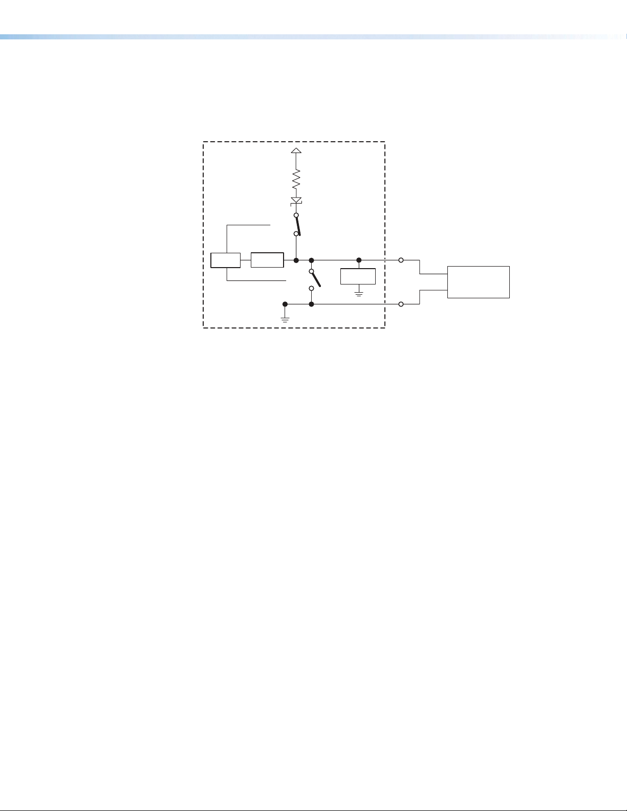
• Example application, analog input with pull-up: adjusting audio levels using a
10k potentiometer
In this example, the flex I/O port is configured for analog input, and it supplies
a pull-up voltage to the potentiometer. The position of the 10k potentiometer
determines the voltage that this port provides, ranging from 0VDC to 4.15VDC.
+5.0 V
1k ohms
SW 2
Flex
CTL
A/D
Converter
SW 1
Voltage
Protection
I/O
10k
Potentiometer
GND
Figure 30. Flex I/O Analog Input Application:
Audio Level Adjustment Using a 10k Potentiometer
IPCP Pro Q xi and xi Series • Hardware Features and Installation 36
Page 45

Digital input — To allow the IPCP to monitor external devices that do not use RS-232
communication, connect a switch, motion sensor, moisture sensor, tally feedback
output, button pad, relay contact, or a similar item to a Flex I/O port, and configure it for
digital input.
When configured as a digital input, the port is set to measure two states: high and low.
The port accepts 0 to 25.3 VDC input.
For Flex I/O ports, threshold voltages are adjustable. Default thresholds are:
• 2.0VDC — port on, logic low
• 2.8VDC — port off, logic high
There is also an internal, selectable, pull-up resistor connected to +5VDC, which you
can use if the connected device does not provide its own power.
• Flex I/O digital input with pull-up disabled:
• Digital input is triggered by an external switch or voltage between the digital
input pin and ground.
• Threshold adjustments can be made from 0.0 VDC to 25.3 VDC in 100 mV steps.
• Example application, digital input without pull-up: occupancy sensor
connection
+5.0 V
1k ohms
CTL
SW 2
A/D
Converter
SW 1
Voltage
Protection
Flex
I/O
GND
Control
Signal
Ground
Occupancy
Sensor
Figure 31. Flex I/O Digital Input Application:
Occupancy Sensor, Without Pull-up
Room occupied: logic high, front panel LED is off.
Room unoccupied: logic low, front panel LED is lit.
NOTE: Occupancy sensors typically supply +24VDC (logic high) when
occupancy is detected. After a set time with no occupancy, the sensor
supplies 0VDC (logic low).
IPCP Pro Q xi and xi Series • Hardware Features and Installation 37
Page 46

• Flex I/O digital input with pull-up enabled:
• When the port is configured for pull-up, switch 2 is closed, activating the
+5.0VDC pull-up resistor.
• An external short to ground creates a logic low.
• An open circuit creates a logic high
• Example application, digital input with pull-up: connecting a two-position
switch
+5.0 V
1k ohms
Two-position
Switch
SW 2
Flex
CTL
A/D
Converter
SW 1
Voltage
Protection
I/O
GND
Figure 32. Flex I/O Digital Input Application:
Two-position Switch With Pull-up
Two-position switch is open: logic high, front panel LED is off.
Two-position switch is closed: logic low, front panel LED is lit.
Digital output — To activate LEDs, control incandescent lights, or power other
devices that accept a TTL signal; or to provide contact closure control for projector lifts,
motorized screens, room or light switches via an Extron IPATRLY4 or similar device,
you can use one or more of these ports as a digital output. When a port is configured
for digital output, it offers two output states: on and off.
• When the port is set to an “on” state, (the switch 1 circuit is closed), the I/O pin is
connected to ground. Output voltage is less than 0.5volts.
• When the port is set to the “off” state (the switch 1 circuit is open), the output pin
floats (is not connected).
• If the application calls for TTL compatibility, the digital output circuit can be set up
to provide a 2kohm pull-up resistor to +5VDC, which you can use if the connected
device does not provide its own power.
• If the pull-up resistor is disabled, voltage output is determined by an external
source device.
• If the pull-up resistor is enabled, switch 2 closes, voltage output is 4.3VDC.
Each I/O port is capable of accepting 250mA, maximum.
IPCP Pro Q xi and xi Series • Hardware Features and Installation 38
Page 47

• Flex I/O digital output with pull-up disabled:
l
R =
V
- V
i
5 V - 2 V
0.005 A
600 ohmsR =
V
- V
i
• When switch 1 closes, the port is on and the front panel LED is on.
• When switch 1 opens, the port is off and the front panel LED is off.
• Example application, digital output without pull-up: connecting an LED
and an external +5VDC power source
This application often requires a current-limiting resistor, as shown in the
diagram below. Many button switches that contain LEDs have a resistor built in.
See the guide for the lighted switch or stand-alone LED for details.
NOTE: Each flex I/O pin is capable of sinking a maximum of 250 mA.
+5.0 V
1k ohms
Resistor
(R)
LED
+
SW 2
Flex
CTL
A/D
Converter
SW 1
Voltage
Protection
I/O
GND
Figure 33. Flex I/O Digital Output Application:
LED and External +5VDC Power Source Without Pull-up
To determine the value of the current limiting resistor in the circuit shown above,
you need to know the values of three variables:
i = LED forward current in amps (found in the data sheet for the LED)
Vf = LED forward voltage drop in volts (found in the data sheet for the LED)
Vs = supply voltage of the external voltage source
Insert those values into the following equation to determine the resistor value:
s
f
Example calculation:
i = 5 mA (0.005 A)
s
Vf = 2 V
Vs = 5 V
}
f
=
=
-
Externa
+5 VDC
Power
Source
NOTE: If the value calculated for the current limiting resistor is not a
standard resistor value, you can round up the number to the next highest
common resistance value.
The connected LED is off when the port (switch 1) is open.
The connected LED is on when the port (switch 1) is closed.
IPCP Pro Q xi and xi Series • Hardware Features and Installation 39
Page 48

• Flex I/O digital output with pull-up enabled:
• When the port is configured for pull-up, switch 2 is closed, activating the
+5.0VDC pull-up resistor.
• When switch 1 closes, the port is on and the front panel LED is on.
• When switch 1 opens, the port is off. The front panel LED is off.
• Example application, digital output with pull-up: controlling another device
via its contact closure input port
Connect the flex I/O port to the contact input port of another device, such
as an Extron DTP transmitter. When activated, the flex I/O digital output port
momentarily closes switch1, which selects the input on the connected device.
+5.0 V
1k ohms
DTP T UWP 232 D
SW 2
+–
Tx Rx G
A/S
CTL
A/D
Converter
SW 1
Voltage
Protection
Flex
I/O
R
- POWER
12V
A MAX
DTP
DTP T UWP 232 D
RS-232
Tx Rx
CONTACT
G12
SIG LINK
DTP OUTREMOTEOVER
GND
Figure 34. Flex I/O Digital Output Application With Pull-up:
Contact Closure Input Selection on a Connected Device
IPCP Pro Q xi and xi Series • Hardware Features and Installation 40
Page 49

Digital I/O (digital input/output) ports — These ports work the same way the flex
Front Panel,
1
I
I/O ports work, but they do not offer analog input, and thresholds are not adjustable.
Connect physical switches, sensors, LEDs, relays, or similar items to these ports (see
figure 14 on page20, figure 15 on page21, and figure 16 on page22), which
can be configured as digital inputs or outputs, with or without +5VDC pull-up. These
ports can trigger events or functions (such as triggering relays, issuing commands, or
sending an e-mail) that have been set up using Global Configurator.
Front/Top Panel,
DIN Rail Models
1 2 3 4 G
DIGITAL I/O
+V +S -S G
PWR OUT = 6W
eBUS
Heat Shrink
Over
Shield Wires
G
4
3
2
Rear Panel,
Rack Mount Models
DIGITAL I/O
1 2 3 4 G
Shrink
Shield
Wires
G
4
3
2
1
Heat
Over
Switch,
Sensor
Digital I/O (digital input/output)
Congure each port as a digital input or output,
with or without +5 VDC pull-up. Use these
ports to:
• Monitor or trigger events and functions (toggle
relays, issue commands, send e-mail), once
congured.
• Power LEDs or other devices that accept a
TTL signal.
Ground
Wire
Nut
Share the same ground
among I/O connections.
Device 4
Device 3
Device 2
Device 1
(Switches, sensors,
LEDs, relays, or
similar items)
Rack Mount
Models
I/O
2
314
Digital I/O LEDs
Light when the
corresponding ports
are active.
For digital input
On: logic low
Off: logic high
For digital output
On: port is on
Off: port is off
Figure 35. Digital I/O Port Wiring Examples
Digital input — To allow the IPCP to monitor external devices that do not use RS-232
communication, connect a switch, motion sensor, moisture sensor, tally feedback
output, button pad, or a similar item to a digital I/O port and configure it for digital input.
When configured as a digital input, the port is set to measure two states: high and low.
The port accepts 0 to 25.3 VDC input.
Unlike flex I/O ports, for digital I/O ports, threshold voltages are not adjustable.
Thresholds are:
• 2.0VDC — port on, logic low
• 2.8VDC — port off, logic high
There is also an internal, selectable, pull-up resistor connected to +5VDC, which you
can use if the connected device does not provide its own power.
IPCP Pro Q xi and xi Series • Hardware Features and Installation 41
Page 50

• Digital I/O digital input with pull-up disabled:
• Digital input is triggered by an external switch or voltage between the digital
input pin and ground.
• Example application, digital input without pull-up: occupancy sensor
connection:
+5.0 V
1k ohms
CTL
SW 2
SW 1
Voltage
Protection
Digital
I/O
GND
Control
Signal
Ground
Occupancy
Sensor
Figure 36. Digital I/O Digital Input Application:
Occupancy Sensor, Without Pull-up
Room occupied: logic high, front panel LED is off.
Room unoccupied: logic low, front panel LED is lit.
NOTE: Occupancy sensors typically supply +24VDC when occupancy is
detected. After a set time with no occupancy, the sensor supplies 0VDC.
IPCP Pro Q xi and xi Series • Hardware Features and Installation 42
Page 51

• Digital I/O digital input with pull-up enabled:
• When the port is configured for pull-up, switch 2 is closed, activating the
+5.0VDC pull-up resistor.
• When an external switch closes (shorts to ground, logic low), the port is on and
the front panel LED is on.
• When the external switch opens (logic high), the port is off. The front panel LED
is off.
• Example application, digital input with pull-up: connecting a two-position
switch
+5.0 V
1k ohms
Two-position
Switch
SW 2
Digital
CTL
SW 1
Voltage
Protection
I/O
GND
Figure 37. Digital I/O Digital Input Application:
Two-position Switch With Pull-up
Two-position switch is open: logic high, front panel LED is off.
Two-position switch is closed: logic low, front panel LED is lit.
IPCP Pro Q xi and xi Series • Hardware Features and Installation 43
Page 52

Digital output — To activate LEDs, incandescent lights, or other devices that accept
l
a TTL signal, or to provide contact closure control for projector lifts, motorized screens,
room or light switches via an Extron IPA T RLY4 or similar device, you can use one or
more of these ports as a digital output. When a port is configured for digital output, it
offers two output states: on and off.
• When the port is set to an “on” state, (the switch 1 circuit is closed), the I/O pin is
connected to ground. Output voltage is less than 0.5volts.
• When the port is set to the “off” state (the switch 1 circuit is open), the output pin
floats (is not connected).
• If the application calls for TTL compatibility, the digital output circuit can be set up
to provide a 2kohm pull-up resistor to +5VDC, which you can use if the connected
device does not provide its own power.
• If the pull-up resistor is disabled, voltage output is determined by an external
source device.
• If the pull-up resistor is enabled, switch 2 is closed, voltage output is 4.3VDC.
Each I/O port is capable of accepting 250mA, maximum.
• Digital I/O digital output with pull-up disabled:
• When switch 1 closes, the port is on and the front panel LED is on.
• When switch 1 opens, the port is off and the front panel LED is off.
• Example application, digital output without pull-up: connecting an LED
and an external +5VDC power source
This application often requires a current-limiting resistor, as shown in the
diagram below. Many button switches that contain LEDs have a resistor built in.
See the guide for the lighted switch or stand-alone LED for details.
NOTE: Each I/O pin is capable of sinking a maximum of 250 mA.
Resistor
(R)
LED
CTL
+5.0 V
SW 2
SW 1
1k ohms
Voltage
Protection
Digital
I/O
GND
Figure 38. Digital I/O Digital Output Application:
LED and External +5VDC Power Source Without Pull-up
+
-
Externa
+5 VDC
Power
Source
IPCP Pro Q xi and xi Series • Hardware Features and Installation 44
Page 53

To determine the value of the current limiting resistor in the circuit shown above,
R =
V
- V
i
5 V - 2 V
0.005 A
600 ohmsR =
V
- V
i
you need to know the values of three variables:
i = LED forward current in amps (found in the data sheet for the LED)
Vf = LED forward voltage drop in volts (found in the data sheet for the LED)
Vs = supply voltage of the external voltage source
Insert those values into the following equation to determine the resistor value:
s
f
Example calculation:
i = 5 mA (0.005 A)
s
Vf = 2 V
Vs = 5 V
}
f
=
=
NOTE: If the value calculated for the current limiting resistor is not a
standard resistor value, you can round up the number to the next highest
common resistance value.
The connected LED is off when the port and switch 1 are open.
The connected LED is on when the port and switch 1 are closed.
• Digital I/O digital output with pull-up enabled:
• When the port is configured for pull-up, switch 2 is closed, activating the
+5.0VDC pull-up resistor.
• When switch 1 closes, the port is on and the front panel LED is on.
• When switch 1 opens, the port is off, and the front panel LED is off.
• Example application, digital output with pull-up: controlling another device
via its contact closure input port
Connect the digital I/O port to the contact input port of another device, such
as an Extron DTP transmitter. When activated, the digital I/O digital output port
momentarily shorts pin 1 to ground (pulsed contact for 0.5seconds), closes
switch1, which selects the input on the connected device.
+5.0 V
1k ohms
DTP T UWP 232 D
SW 2
- POWER
12V
+–
A MAX
Tx Rx G
DTP
DTP T UWP 232 D
RS-232
Tx Rx
CONTACT
G12
A/S
SIG LINK
DTP OUTREMOTEOVER
CTL
SW 1
Voltage
Protection
Digital
I/O
GND
R
Figure 39. Digital I/O Digital Output Application With Pull-up:
Contact Closure Input Selection on a Connected Device
IPCP Pro Q xi and xi Series • Hardware Features and Installation 45
Page 54

Front/Top Panel,
DIN Rail Model
PWR OUT = 12W
+V +S -S G
eBUS
+V +S -S G
PWR OUT = 6W
eBUS
Drain Wires
+V +S -S G
PWR OUT = 6W
Rear Panels,
Rack Mount Models
PWR OUT = 12W
+V +S -S G
+V
+12 VDC
+S
+ Signal
-S
- Signal
G
Ground
eBUS port (see figure 14 on page20, figure 15 on page21, and figure 16
J
on page22) — eBUS is a technology (proprietary bus architecture and serial
communication protocol) developed by Extron. It allows many eBUS devices (such as
button panels) and accessories (including power and signal hubs) to be connected
to a single control processor to expand the capabilities of a control system. Button
panels are automatically recognized by the host control processor and can be added or
removed at any time.
See the eBUS Technology Reference Guide (part 68-1499-01) before you install eBUS
devices and accessories. It explains how to determine how many devices are supported
when directly connected to the control processor and where (at what distances and
what points in a system) and when it is advisable to add external power supplies. Also
see the guide for each eBUS device for detailed installation information specific to each
product, such as how to set the eBUS address and mount the devices. Each device in
a system must have a distinct eBUS address that is not shared with any other device in
the same system.
Wire both ends the same on each cable that connects eBUS devices. Extron STP20
Series cable is recommended for these connections (see the cable preparation
diagram on page28).
eBUS Link LED (green)
Lights steadily and remains lit
when the unit detects connected
eBUS devices, there are no ID
conicts, and eBUS rmware is
not currently being synchronized.
eBUS
eBUS
eBUS
+V
+S
-S
G
+12 VDC
+ Signal
- Signal
Ground
port on
device
eBUS Busy LED (amber)
Blinks while eBUS rmware is
being synchronized.
eBUS Error LED (red)
Blinks if the unit detects an
eBUS ID conict.
eBUS Accessory Port
Connect the rst eBUS device to this port, then connect
other eBUS devices and accessories to that device in
the desired topology (daisy chain, star, or combination).
• Wire the connectors the same at both ends for every
eBUS device.
• See the eBUS Technology Reference Guide for the
recommended distance from the control processor to
the last eBUS device and maximum quantity of
devices per control processor.
• The IPCP can provide power to the button panel
devices.
eBUS port on an
eBUS device
(button panel or
similar device)
eBUS
an
eBUS
ON
DISPLAY
VOLUME
VIDEO
OFF
PC
LAPTOP
DOC CAM
PC
DVD
VIDEO
VOLUME
MUTE
LINK
LIMIT
BUSY
ERROR
OVER
Front Panels,
Rack Mount Models
eBUS
S LIMIT
OVER
LED is not lit — This indicates one of
the following conditions:
• No power is present.
• No eBUS devices are detected.
LED is blinking fast — An eBUS ID
conict has occurred: two devices
have the same bus ID number.
LED is blinking slowly — A rmware
update is in progress: the control
processor is synchronizing rmware
of the eBUS panel(s).
LED is lit steadily — Power is present with
conrmed communication and there are
no eBUS ID conicts in the entire system.
eBUS Limit LED
(amber)
Lights steadily and
remains lit while the
eBUS port uses the
maximum threshold
power.
eBUS Overload LED
(red)
Lights steadily when the
eBUS port exceeds
maximum threshold
power usage and enters
the fault state.
During this fault state,
eBUS port power is
shut down until the
power usage falls back
below the threshold.
The Over LED remains
lit during the fault state.
eBUS Status LED (green)
Figure 40. eBUS Port Cabling and Front Panel LED Indication
IPCP Pro Q xi and xi Series • Hardware Features and Installation 46
Page 55

This port provides power to eBUS devices. If the power draw by the connected
devices reaches the maximum level allowed, the eBUS Limit LED lights. If the power
consumption exceeds the allowed threshold, the IPCP shuts off the eBUS port and
lights the eBUS Overload (Over) LED. If that occurs, you must resolve the hardware
cause of the power overload before the IPCP can successfully restore function to this
port. Once the power consumption of the port is reduced to below the maximum
overload condition threshold, the eBUS port automatically re-enables and resumes
function.
If additional power supplies are required for an eBUS system, consider the following:
• Do not connect power from both the IPCP and the supplemental power supply to
any eBUS device.
• Do not allow power from the supplemental power supply to flow to the IPCP.
See the following diagram as an example of a system where both an IPCP and a
supplemental power supply are included in the eBUS topology.
EBDB MINI
Rear Panel
(or use
an EBDB
10-port hub)
ATTENTION:
• Do NOT connect the power pin to
• NE connectez PAS la broche
ATTENTION: Do NOT
any device that is already powered
by the IPCP control processor or by
an a dditional power s uppl y.
d'alimentation à un appareil déjà
alimenté par le processeur de
contrôle IPCP ou par une autre
connect the power pin
to any device that is
already powered by the
IPCP Pro control
proc essor or by an
additional power supply.
source d'alimentation.
Figure 41. Connecting eBUS Devices in a System With Both an IPCP and
eBUS DISTRIBUTION HUB
+
V G-S+S+V G-S+S+V G-S+S
X
G-S+S
Powered
G-S+S
eBUS
device(s)
G-S+S
+V
+V
Tie drain wires to ground.
• Connect up to four (4) eBUS devices to the
eBUS distribution hub (EBDB MINI).
• Wire the connectors the same at both ends.
G-S+S
+12 VDC
+V
+S
+ Signal
-
S
-
Signal
G
Ground
IPCP
Rear Panel
Another Powered eBUS Device
eBUS Connections
3/16" (5 mm) Max.
eBUS
-S+V +S G
PWR OUT = 6W
G-S+S
+V
+
V
+
S G
–
S
Tie drain wires to ground.
eBUS port on an
EBP or other
eBUS device
IPCP Pro Q xi and xi Series • Hardware Features and Installation 47
Page 56

Reference voltage
V
Rear Panel,
Rack Mount
Models
VOL
V C G
Volume control port — To provide volume control for some Extron half rack audio
K
amplifiers (such as the XPA and MPA models listed in figure 19), connect this port (see
figure 14 on page20 and figure 15 on page21) to the volume remote control port
on the amplifier as shown below. Configure the maximum and minimum voltage limits.
Set Soft Start mode off or on (default). Soft Start mode allows volume to gradually
increase from mute to the previous level after muting or power-on to prevent loud audio
bursts.
Reference
voltage: ≤10 VDC
V C G
Control voltage output:
0 - 10 VDC
Ground (Gnd)
G
Control voltage (variable output to amp from IPCP Pro) – This signal controls the amp volume.
C
Reference voltage input (from amplier) – This allows the IPCP Pro to detect when the amp is present.
V
This port can be used to control the volume and mute or
unmute the audio for Extron half rack width audio ampliers.
• Connect to an Extron audio amplier to permit volume
control via touchpanel controls, macros, or schedules.
• Do not exceed 10 VDC input voltage.
Congure the maximum and minimum voltage limits. Set
Soft Start mode off or on (default). Soft Start mode allows
volume to gradually increase from mute to the previous level
after muting or power-on to prevent loud audio bursts.
Volume Control
NOTE:
Use shielded
cable and place the
control processor as
close as possible to
the amplier to avoid
picking up background
noise via the cable.
Ideal cable length is
six feet (1.8 m) or less.
Example:
Connecting to
Extron Amplifiers
VOL
V C G
IPCP
Rear
Panel
Ground
G
Control voltage
C
XPA 10 02
10V 50mA
GCV
G
STANDBY
MPA 401 Series
REMOTE
10V 50mA
10V 50mA
MPA 181T,
MP 101 Series
REMOTE
10V
VOL/MUTE
GCV
MPA 152MPA 152 Plus
REMOTE
GCV
C or
V or 10V G or
VOL/MUTE
10V 50mA
VOL/MUTE
Figure 42. Volume Control Port Wiring Examples
NOTE: When audio mute is active,
the control processor sets output
voltage to
0 VDC, even if the
voltage range (minimum and
maximum voltage limits) has been
set to levels above zero, such as
2 V to 8 V.
IPCP Pro Q xi and xi Series • Hardware Features and Installation 48
Page 57

Resetting the Unit
Reset
Button
There are six reset modes that are available by pressing the
Reset button on the front panel. The Reset button is recessed, so use
a pointed stylus, ballpoint pen, or Extron Tweeker to access it. See the
reset modes table below and on the next two pages for a summary of the
modes.
ATTENTION:
NOTE: If you press and hold the Reset button continuously, the LED blinks every
IPCPProQxi and xi Series Control Processor Reset Mode Summary
Use This
Mode to...
Mode
Temporarily
boot up the
unit running
only the
universal
boot code,
then install
the desired
firmware.
Use this in
the event that
a firmware
update has
failed or if
incompatibility
Run Universal Boot Code
issues arise
with userloaded
firmware
Activation Result
To start the Run Universal Boot Code reset mode and replace
firmware:
1. On the control processor, hold down the recessed Reset
button while applying power to the unit. Keep holding the
button down until the Power LED blinks twice, then release
the button. The LED blinks slowly during bootup. The control
processor runs the universal boot code (rather than full
firmware).
2. Upload new firmware to the unit as desired (see Updating the
Firmware on page66 for details).
NOTE: Do not continue to operate the control processor
using only the boot code. The unit requires a full firmware
package in order to be fully operational. If you want to use
the firmware version with which the unit shipped, you must
upload that version again (see the Global Configurator Help
File or Toolbelt Help File for firmware upload instructions).
R
• Review the reset modes carefully. Using the wrong reset mode
may result in unintended loss of flash memory programming, port
Power
LED
reassignment, or a unit reboot.
• Analysez minutieusement les différents modes de réinitialisation.
Appliquer le mauvais mode de réinitialisation peut causer une
perte inattendue de la programmation de la mémoire flash, une
reconfiguration des ports ou une réinitialisation de l’unité.
3seconds, and the unit enters a different mode, from the Reset All IP Settings mode
through the Reset to Factory Defaults mode. For Reset to Factory Defaults mode
the LED blinks three times, the third blink indicating the last mode. The modes are
separate functions, not a continuation from one mode to the next.
The control processor firmware is
replaced. If the unit is powered on in Run
Universal Boot Code mode, event scripts and
systems do not start. All user files and settings
such as drivers, adjustments, and IP settings
are maintained.
NOTE: To return the unit to the firmware
version that was running prior to the
reset, cycle power to the unit instead of
installing new firmware.
IPCP Pro Q xi and xi Series • Hardware Features and Installation 49
Page 58

IPCPProQxi and xi Series Control Processor Reset Mode Summary
Use This
Mode to...
Mode
Recover
project
configuration
and program
files if
passwords
have been lost
Project Recovery
Toggle stop/
start program
Run/Stop Program
Enable or
disable the
DHCP client
Toggle DHCP Client
Reset IP
settings and
port maps
to factory
defaults
without
affecting userloaded files
Reset All IP Settings
Activation Result
To start the Project Recovery reset mode and recover a project:
1. On the PC, open your choice of Extron control software.
2. Open the help file for that software.
3. Locate and read instructions on how to perform project
4. Perform project recovery and save the recovered project.
5. Perform the Reset to Factory Defaults reset (see the next
6. Open Toolbelt and use it to set up network settings and
7. Close Toolbelt.
8. In your choice of control software, add the new password to
9. Save the project.
10. Upload the project from the software to the control processor.
To stop or start scripts, and systems:
1. Press and hold the Reset button for about 3 seconds, until
2. Release and press the Reset button momentarily (for
To enable or disable the DHCP client for the LAN port:
1. Press the Reset button five times (consecutively).
2. Release the button. Do not press the button within 3seconds
To reset all IP settings:
1. Press and hold the Reset button for about 6seconds until
2. Release and press the Reset button momentarily (for
Project Recovery mode stops regular
operation and allows a connection to be
made to the unit via software without
requiring password entry so that project
files can be retrieved and saved.
recovery.
• During project recovery mode, events are
stopped, and so is communication with AV
devices.
page) on the control processor.
• While the control processor is in this mode,
use the software to recover project files.
passwords.
• Upon exiting project recovery mode:
• The unit returns to its pre-recovery mode
state and settings.
the recovered project.
• The Power LED returns to being steadily
lit.
The LED blinks 2 times if the program is
starting.
the Power LED blinks once.
The LED blinks 3 times if the program is
stopping.
<1second) within 1second*.
* Nothing happens if the momentary press does not occur
within 1second.
• The Reset LED blinks 6 times if the DHCP
client is enabled.
• The Reset LED blinks 3 times if the DHCP
following the fifth press.
client is disabled.
NOTES:
• By default DHCP is off for the LAN port.
• If DHCP has been enabled, when you disable DHCP, the unit reverts to using the previously-set static
IPaddress.
Reset All IP Settings mode:
the Power LED blinks twice (once at 3 seconds, again at
6seconds).
<1second) within 1second*.
* Nothing happens if the momentary press does not occur
within 1second.
NOTE: This resets the settings for both LAN and AV LAN
ports
• Turns DHCP off (for LAN ports).
• Sets the LAN and AV LAN IP addresses
back to factory default:
• LAN port, xi models: 192.168.254.250
• LAN port, Q xi models:
192.168.253.250
• AV LAN port (Q xi models, DHCP server
disabled):
192.168.254.250
• Sets the subnet back to factory default
(255.255.255.0).
• Sets the default gateway address to the
factory default (0.0.0.0).
• Sets domain and host names to factory
default.
• Sets port mapping back to factory default.
• Turns events (user-created schedules,
macros) off.
• Stops any running program.
• Disables 802.1X authentication.
IPCP Pro Q xi and xi Series • Hardware Features and Installation 50
Page 59

IPCPProQxi and xi Series Control Processor Reset Mode Summary
Use This
Mode to...
Mode
Start over with
configuration
and uploading
Reset to Factory Defaults
Activation Result
To reset the unit to all factory default settings:
1. Hold down the Reset button for about 9seconds until the
Power LED blinks three times (once at 3 seconds, again at
6seconds, again at 9 seconds).
2. Release and press the Reset button momentarily (for
<1second) within 1second*.
* Nothing happens if the momentary press does not occur
within 1second.
Reset to Factory Defaults mode performs
a complete reset to factory defaults
(except the firmware).
• Does everything Reset All IP Settings mode
does.
• Removes (clears) all user-loaded files (except
LinkLicense files) and configurations from
the control processor:
• Clears driver-port associations (IR, serial,
Ethernet) and port configurations.
• Removes button/touchpanel
configurations.
• Removes user-loaded digital certificates.
• Removes schedules, settings, macros.
• Clears messages in the event logs table.
NOTES:
• After performing a Reset All IP Settings or Reset to Factory Defaults reset, either set the IP address
again (by using Toolbelt) for use on your network, or turn DHCP on.
• The factory configured password for this device has been set to the device serial number. Passwords
are case sensitive. Performing a Reset to Factory Defaults reset sets the password to extron.
IPCP Pro Q xi and xi Series • Hardware Features and Installation 51
Page 60

Software-Based Configuration and Control
This section of the guide is divided into the following topics:
• Configuration and Control: an Overview
• Basic Setup Steps: a Guide to this Section and Other Resources
• Downloading the Software and Getting Started
• Troubleshooting
Configuration and Control: an Overview
An IPCP must be configured before use in order to recognize and accept commands
and pass them on to the controlled devices. It can be configured and controlled via a host
computer connected to the same network as the control processor (see LAN (Ethernet)
connectors and LEDs starting on page29 for details about LAN port and cabling to
connect the control processor to the network).
• Configure the control processor by using the Global Configurator software
(GCProfessional or GC Plus) (see the Extron website for full system hardware and
software requirements for GC), or program it using Global Scripter.
• The default web pages embedded within the control processor provide a means to view
general hardware information, network settings, and, if configured, project information.
The embedded web pages can also be used to update the IPCP firmware. You cannot
configure the control processor via the embedded web pages.
IPCP Pro Q xi and xi Series • Software-based Configuration and Control 52
Page 61

Basic Setup Steps: a Guide to this Section and Other Resources
NOTE: GC projects can be created offline and uploaded to the hardware at a later date.
Follow the steps in Setup Checklist: How to Proceed With Installation starting on
page10. The overall process for setting up a control processor using GC is as follows:
Within Global Configurator
(GC Professional or
GC Plus mode):
Create a new GC Professional or GC Plus project
No Yes
Configure the IP settings
of the control processor,
NBP network button panels, and
TouchLink Pro touchpanels.
If desired or required, use
Toolbelt or other software to congure
security settings for 802.1X, SSL.
Upload security certicates, private keys.
and add the control processor to it.
Will
TouchLink Pro or
third party touchpanels or
other user interfaces
be used?
Create GUI layouts for the
touchpanels or other interfaces:
1. Start GUI Designer.
2. Create GUI layout designs for each
TouchLink Pro, third party
touchpanel (with a TouchLink
Interface), or a computer or
mobile device (with LinkLicense).
3. Save and build the GUI layout le.
Or...
Download existing GUI layouts
from identical touchpanels.
See Network
Communication Setup
Communication Setup
Network
on page13.
Congure ports on the
control processor.
Create monitors, schedules, timers,
macros, and local variables.
Add touchpanels, other interfaces, or
button panels (if used) to the project.
Import GUI layouts and congure the
touchpanels or other interfaces.
Save the project.
Build and upload the conguration to
the control processor.
Test the system, make adjustments,
nalize conguration.
Figure 45. Overall Configuration Steps
IPCP Pro Q xi and xi Series • Software-based Configuration and Control 53
Page 62

Downloading the Software and Getting Started
GC software updates and a large variety of device drivers can be downloaded from the
Download page on the Extron website (www.extron.com/download/index.aspx).
When you locate the desired software or driver package, follow the on-screen directions to
download and install it.
NOTE: New RS-232 and Ethernet drivers are required. Use serial and Ethernet
drivers developed specifically for the IPLinkPro platform. With the exception of IR
device drivers, drivers used for the previous generation IPLink (non-Pro) control
processors are not compatible.
Locating Software, Firmware, and Driver Files on the Extron Website
There are three main ways to find software, firmware, and device drivers within
www.extron.com:
• Via links from the web page for the specific product
• Via the Download Center page (Click on the Download tab at the top of any page
within the Extron website.)
• Via links from search results
NOTE: For some software you have the option to click the Download button to begin
downloading the software file. For other software there is a link for contacting an
Extron support representative who can provide you access to the latest version.
To obtain Extron control product software, you must have an Extron Insider account
and contact an Extron support representative. Extron provides training to our
customers on how to use the software. For Global Configurator Professional, you
must first attend Extron training, pass a proficiency test, and achieve Extron Control
Professional Certification before being able to access all the features of that program.
Via links from the web page for the specific product
1. Navigate to the web page for the specific product model by performing one of the
following:
• Enter the model name into the search field in the upper right of any Extron web
page and click the magnifying glass icon.
Or...
• Select the model name from the Product Shortcuts drop-down list in the
upper left of the Extron home page or Products page.
2. Click the Downloads tab in the middle of the product page. A list of available software,
firmware, and documents for that model appears on screen.
3. Click on the name of the desired software or firmware to start downloading the file, or
click on the link for device drivers to navigate to a page from which you can select either
a driver package or specific drivers for individual devices.
Via the Download Center page
1. Click on the Download tab at the top of any page within the Extron website to access
the Download page.
2. Click on the link for the desired software product category (such as Global Configurator
Professional, firmware, or control system device drivers) in the center of the screen. A
page opens that allows you to make more specific selections from within that category.
IPCP Pro Q xi and xi Series • Software-based Configuration and Control 54
Page 63

3. For software, click on the link for the specific software that you need. A software
product page opens that provides a description of the software package, a list of
system requirements, a list of features, and access to the release notes, in addition to a
download link.
For drivers:
a. Click on the Control System Drivers button.
b. Select the name of the control processor from the drop-down list.
c. Click the link directly below the search fields to download the current “Pro Series
driver package” of all available drivers supported by the control processor.
Alternatively, search for, locate, and select the device or devices for which you need
a driver file.
d. To download a single driver rather than the package, click on the appropriate link in
the row for the product you want to control to download the driver or to download
the “communication sheet.” The communication sheet provides details that may be
helpful for working with the product and its control driver.
4. For some software you can click the Download or Download Now button to begin
downloading the software file. For other software there is a link for contacting an Extron
support representative who can provide you access to the latest version.
For drivers, navigate through the alphabetically arranged list to select and download a
driver for a specific device.
Via links from search results
1. Type the specific name of the software package (such as Global Configurator or
GUIDesigner) into the Search field in the upper right of the Extron web page and click
the magnifying glass icon. A search results page appears.
2. Click on the name of the software package. A software product page opens that
provides a description of the software package, a list of system requirements, a list of
features, and access to the release notes, in addition to a download link.
3. For some software you can click the Download or Download Now button to begin
downloading the software file. For other software there may be a link for contacting an
Extron support representative who can provide you access to the latest version.
Obtaining Control Drivers
Extron provides an extensive selection of device drivers available on the Extron website.
Ethernet, serial, and infrared (IR) device drivers (for controlling projectors, displays, DVD
players, document cameras, and so forth) are available as individual device driver files. Prior
to configuration, download driver files for products to be used in the installation.
NOTE: For serial or Ethernet devices, IPCPProxiSeries control processors require
IPLinkPro drivers. They do not support serial or Ethernet drivers that were created for
IPLink (non-Pro) products. However, existing Extron IR driver files are supported.
If the system requires a driver that is not already available, you have additional options:
• Request a new serial (RS-232) or Ethernet driver from Extron.
• Create your own custom IR driver using Extron IRLearner Pro software. Following the
directions in the IRLearnerPro Help File, use the remote control of an AV device and
the IR receiver port on the front panel of the IPCPProxi to capture commands and
create a device-specific driver.
IPCP Pro Q xi and xi Series • Software-based Configuration and Control 55
Page 64

Things to Do After Installing GC and Before Starting a Project
• Read the Global Configurator Help File, included with the software, for details and step-
by-step procedures on how to start a GCProfessional or GCPlus project and perform
basic setup tasks for a control processor. The help file provides a wealth of information
on settings and how to use the software. It includes examples of how to use the
features of GC and step by step instructions for typical configuration tasks.
• Obtain network addresses and related information from your network administrator.
• Set up the IP address for the control processor. See Network Communication Setup
on page13 for an overview of how to set up the network properties of the unit. For
details, see the GC help file or Toolbelt help file. The help files contain instructions on
how to set the IP address, gateway IP address, subnet mask, mail server IP address,
domain name, web port, SMTP username, and SMTP password so that the IPCP is
able to communicate with the network.
Using GC: Helpful Tips
Resources and notes
• The IPCPProxi Series Setup Guide, IPCPPro355DRQ xi Setup Guide, or
IPCPProPCS1xiSetupGuide is shipped with the unit. It includes a quick reference to
the front and rear panel features, and covers basic hardware installation.
• See Front Panel Features on page14 and Ports, Addressing, and Connections
on page19 in this guide for features and settings for the ports you are configuring.
• If you plan to configure the IPCP at the installation site, Extron recommends
downloading drivers for all the devices in the installation before you go out to the site.
• The Global Configurator project file (*.gcpro or *.gcplus) contains configuration settings
and it can be saved to a directory or folder for backup or for installation on another
IPCPProxi control processor. Saving a configuration is recommended before you
perform a firmware upgrade.
• IP address, subnet mask, and gateway address are required during network setup of
the control processor.
• The unit name is any name (for example, Room730-IPCPPro550xi or ConfRmSystem)
that you want to use to label a specific IPCP unit. The default is a combination of the
product name and part of the hardware (MAC) address. This can be changed to your
choice of alphanumeric characters and hyphens (-). The following rules apply:
• Spaces are not permitted within the name of a unit or at the start or the end of a
name.
• Underscores ( _ ) are not permitted.
• Valid characters are A-Z, a-z, 0-9, and - (hyphen).
• The unit does not distinguish between upper and lower case letters.
• The name cannot start with a number or a hyphen, and it cannot end with a
hyphen.
• Maximum name length is 63 characters.
IPCP Pro Q xi and xi Series • Software-based Configuration and Control 56
Page 65

Troubleshooting
Power Connections
Turn on the input devices (DVD players, Blu-ray players, PCs, and other sources), output
devices (display screens, projectors), the control processor, and the PC and touchpanel or
eBUS button panels. Touch a configured button on the touchpanel or eBUS button panel.
If an input or output AV device cannot be remotely controlled (does not respond as
expected), check the following:
• Power Connections
• Data Connections
• Device Control Connections and Configuration
• eBUS Connections and Configuration
• Ensure that all devices are plugged in.
• Make sure that each device is receiving power. The IPCP front panel power LED lights if
the IPCP is receiving power.
• If the IPCP includes switched power output ports, verify that the overload indicator LED
is not lit. If the switched 12 VDC power output Over LED is lit, the power draw at the
switched power ports has been exceeded. To restore these ports to normal function, do
the following:
1. Correct the hardware cause of the overload. Disconnect one or more devices from
the 12VDC switched power output ports on the IPCP. The IPCP waits a moment
and rechecks the power load.
• If the total load (power draw) is now within safe limits, the IPCP automatically
re-enables the ports. The green switched 12VDC power status LEDs on the
IPCP light, the red OverLED is unlit, and power is restored to the output ports.
• If the total load still exceeds the maximum threshold, the OverLED remains lit
and the ports remain off until the overload is corrected (see step 2).
2. Repeat step 1 (disconnect another device from the switched power output ports)
as needed until the OverLED turns off and all the green switched 12VDC power
status LEDs on the IPCP light.
• For the IPCPProPCS1xi, if the device connected to the AC power output cable is not
receiving power, check the following items:
• Is the AC output port enabled (turned on) via configuration or script settings, or via
the front panel Power button? The AC Power LED lights to indicate the power output
state as follows:
Lit green: Power output is enabled.
Off (dark): Power output is disabled.
Lit red: A fault condition is detected, and power output is disabled.
• Is there a fault condition at that port? If so, the circuit breaker was triggered. Correct
the fault condition (such as a circuit overload), then press the Breaker button to
reset the circuit breaker.
IPCP Pro Q xi and xi Series • Software-based Configuration and Control 57
Page 66

Data Connections
1. Check the cabling connections and make adjustments as needed. The LinkLEDs
on the IPCP and on the touchpanel, network button panel, or PC should be lit green
steadily if a network connection is detected. If these LEDs are not lit, either the cable is
faulty or not plugged in, or the wrong type of cable is being used (see LAN (Ethernet)
connectors and LEDs on page29).
2. Try to “ping” the unit by entering one of the following at the command prompt on the
PC:
• ping 192.168.254.250 — for a unit without AVLAN, or for an AVLAN port
• ping 192.168.253.250 — for the LAN port of a unit with AVLAN
• ping 192.168.245.1 — for an AVLAN port if the DHCP server is enabled
Or ping the IP or web address provided to you by your system administrator.
If you get no response:
• Make sure your unit is using the appropriate subnet mask (check with your system
• Make sure your PC and network do not have a software firewall program that might
3. If contact is established with the unit, but the IPCP web pages cannot be accessed
by your browser program, verify (via an Internet network options or preferences menu)
that your browser is configured for direct network connection and is not set up to use a
proxy server.
when the DHCP server is disabled (default)
administrator).
block the IP address of the IPCP unit.
Device Control Connections and Configuration
• Verify that ports are wired correctly and that ground (earthing) wires are connected to
the proper pins on the control processor and, if applicable, on the controlled device.
• Ensure that each IR emitter head is placed adjacent to or directly over the IR pickup
window on the controlled device.
• Verify that the appropriate drivers were used while creating the configuration file and that
the correct commands and signal types (IR, RS-232, Ethernet) are associated with the
appropriate ports on the control processor and on the other devices.
• For digital input and output connections, verify whether the application requires the
+5VDC pull-up resistor within the IPCP for TTL circuits, and use the software to check
whether it is selected within the configuration.
• Verify that input current at any digital input or output port does not exceed 250mA.
• Verify that input current at the volume control port (IPCPPro250) does not exceed
10VDC and that the amplifier is cabled correctly, as well.
IPCP Pro Q xi and xi Series • Software-based Configuration and Control 58
Page 67

eBUS Connections and Configuration
• Verify that the eBUS ports are wired correctly and that ground (earthing) wires are
connected to the ground pins on every device in the system. Connectors should be
wired the same at each port.
• Check for eBUS address conflicts. Ensure that each device in the system has a distinct,
individual bus ID address and that no device is set to address zero. When an eBUS
address conflict exists:
• The eBUS status LED on the IPCP blinks fast.
• The devices that share an address do not function.
• The other devices work correctly.
NOTE: If a device bus address is set to zero, it is not recognized by the IPCP.
• If the IPCP does not recognize any connected devices and if the eBUS Overload LED is
lit, power consumption at the eBUS port is too high.
Use one of these methods to restore the eBUS port to normal mode:
• Remove eBUS devices one at a time from the system until the overload no longer
occurs.
• Add supplemental power supplies to the system.
See the eBUS Technology Reference Guide for details.
• Once overload conditions are resolved, the green eBUS status LED on the IPCP lights,
the red eBUS Over LED should be unlit, and eBUS devices resume functioning and are
again recognized by the IPCP.
If you are still experiencing problems, call the Extron S3 Sales & Technical Support
Hotline or the Extron S3 Control Systems Support Hotline (1.800.633.9877).
IPCP Pro Q xi and xi Series • Software-based Configuration and Control 59
Page 68

Reference Information
This section of the guide includes the following reference items:
• Network Port Requirements and Licensed Third-Party Software
• File Types: a Key to Extron-specific File Names
• Secure Sockets Layer (SSL) Certificates
• IEEE 802.1X Certificates
• SNMP
• Unmounting a DIN Rail Unit
To read product specifications, visit the IPCPProxiSeries product pages at
www.extron.com.
Network Port Requirements and Licensed Third-Party Software
Network administrators may find it useful to know which ports, protocols, and
services are used by the IP Link Pro control processors, TouchLink Pro Touchpanels,
Global Configurator Plus and Professional software, Toolbelt, and Extron Control
(for IPLinkPro control systems). A list of protocols used for inbound and outbound
communication for each type of device or software is available in the Pro Series
Control Product Network Ports and Licenses Guide, part 68-2961-01, available at
www.extron.com.
The control processors use various licensed third-party software packages during operation.
To view details about third-party packages and associated licensing, click the License
Information button in the internal web pages of the control processor. A License
Information window opens. To view a copy of a listed package license, in the License
Information window, click the link in the License column for the relevant package. This
opens a copy of the package license in a separate window. A list of licenses is also available
in the Pro Series Control Product Network Ports and Licenses Guide at www.extron.com.
File Types: a Key to Extron-specific File Names
A basic understanding of the types of files used by the control processor is helpful in order
to decide what (if anything) to do with them.
• .eff — This is an Extron firmware update file (see the Firmware Updates section
starting on page65 for details on firmware updates).
• .eir — These are IR driver files containing infrared commands. There is a separate .eir
file for each device the IPCP controls via infrared communication. This is also the type of
file created during IR learning. Via Global Configurator, these files can be imported and
associated with one of the IR ports on a control processor.
• .ell — This is a LinkLicense file. It appears in systems that use a LinkLicense for using a
third-party device as a control interface instead of an Extron TouchLink Pro touchpanel.
• .gcplus — This is a Global Configurator Plus configuration file.
• .gcpro — This is a Global Configurator Professional configuration file.
IPCP Pro Q xi and xi Series • Reference Information 60
Page 69

• .gdl — This is a GUI Designer layout created for TouchLinkPro a touchpanel or
third-party touch interface.
• .glta — This is a GUI layout template.
• .gs – This is a Global Scripter project file.
Secure Sockets Layer (SSL) Certificates
Extron control processors ship with factory-installed SSL certificates created by Extron. If
you want or are required to use a different SSL certificate at your installation site, then you
can use system utilities in the Toolbelt software to change the SSL certificate at any time.
The Toolbelt Help File provides instructions on how to apply an SSL certificate to a control
processor.
NOTES:
• You must run Toolbelt as an administrator.
• Some certificates require a passphrase that is created when the certificate is
created. If a passphrase is required, you must enter that passphrase before
uploading and applying the certificate.
IP Link Pro controllers support standard OpenSSL certificate encodings such as .pem
(Privacy-enhanced Electronic Mail) and .der (Distinguished Encoding Rules) file types.
PEM file types are ASCII encoded and are the required format for uploading to the control
processor. DER file types are binary encoded and can typically have several file extension
variations, such as .crt and .cer. There are many standard tools that can convert from DER
to PEM file encodings if needed.
NOTE: A DER format file must be converted to PEM encoding before uploading it to the
control processor.
To properly create the certificate for uploading to Extron control processors, ensure that the
certificate file meets the following requirements:
• contains X.509 certificate information
• contains public and private keys
• uses PEM encoding
NOTE: ITU-T standard X.509 covers aspects of public key encryption, digital
cryptography, certificates, and validation.
Contact your IT administrator for more information on what tools and policies are required to
obtain or create the SSL certificate and, if necessary, the corresponding passphrase.
IPCP Pro Q xi and xi Series • Reference Information 61
Page 70

IEEE 802.1X Certificates
IEEE 802.1X is a standard that enables port-based network access control via an
authentication server. The protocol requires that all devices must be authenticated before
gaining privileges to access the secure part of the network.
The Extron implementation of 802.1X supports PEAP - MSCHAPV2 and EAP - TLS
methods of authentication. This section of the guide details the requirements for any
certificate file (machine or CA) and the private key file (for the machine certificate) to be
used in the system.
Extron provides resources for learning about 802.1X implementation:
• The Extron 802.1X Technology Reference Guide, available from www.extron.com, is
the primary resource for background information, system planning, topology, and how
to set up these systems.
• The Toolbelt Help file provides detailed step-by-step information on using the software
to set up 802.1X for IPLinkPro control systems and on troubleshooting.
• The 802.1X Primer white paper, also available from www.extron.com, provides a
general overview of the protocol and its use within a control system.
NOTES:
• You must run Toolbelt as an administrator.
• Machine certificates require a private key file, which can be encrypted.
Certificate File Requirements
PEM (Privacy-enhanced Electronic Mail) file types are ASCII encoded, and they are the
required format for 802.1X authentication for the control processors. DER (Distinguished
Encoding Rules) file types are binary encoded and can typically have several file extension
variations, such as .crt and .cer.
NOTE: DER encoded files (files with .der, .crt, or .cer extensions that are encoded in
DER binary format) must be converted to a PEM encoded file type (.pem) before being
used for authentication.
DER encoded certificates must be converted to PEM encoding using a third-party tool.
Contact your IT administrator for more information on required tools.
To create the 802.1X security certificate for uploading to Extron control processors, ensure
that the certificate file meets the following requirements:
• It contains X.509 certificate information.
• It contains a private key (for machine certificates only).
• It is PEM encoded.
• It has a file extension that is .crt or .pem
• Its file name consists of the following types of valid characters:
• Alphanumerical (A-Z, a-z, 0-9) characters
• Some special characters (colon [ : ], underscore [ _ ], and hyphen [ - ])
NOTE: Spaces are not permitted anywhere in the name.
IPCP Pro Q xi and xi Series • Reference Information 62
Page 71

SNMP
Private Key File Requirements
Private key files are required only when employing machine certificates. Follow these
requirements for creating a private key:
• Its file name consists of the following types of valid characters:
• Alphanumerical (A-Z, a-z, 0-9) characters
• Some special characters (colon [ : ], underscore [ _ ], and hyphen [ - ])
• It has a file extension that is .key or .pem.
• It can have optional encryption (via password or passphrase).
Extron control products support Simple Network Management Protocol (SNMP). SNMP
facilitates the exchange of basic network management information between network
devices. It helps in monitoring of operations and factors such as packet usage, memory
usage, remote password resets, and collection of error information. An information
technology administrator can use common IT tools to monitor those factors, as well as look
up device location and the name of the contact person for the device.
The SNMP controls within Toolbelt provide a way to enable or disable SNMP. It also allows
you to specify related information such as the name of a contact person, the physical
location of the unit, and a community name. The text that is specified in these fields is seen
by the network community when the unit is queried.
Extron control products support the following security levels:
• Management Information Base 2 (MIB-II)
• SNMPv2a.
IPCP Pro Q xi and xi Series • Reference Information 63
Page 72

Unmounting a DIN Rail Unit
If the need arises, the IPCPPro355DRQxi can be removed from the DIN rail, whether or
not cables are still attached. Remove or unmount the unit as follows:
1. Pull the mounting clip down to release the unit from the bottom of the rail (see figure 46,
). If you cannot grasp and pull the clip by hand, insert a small, flat-bladed screwdriver
1
(such as an Extron Tweeker) through the slot in the clip and pull it downward.
2. While the clip is pulled down, tilt the IPCPProxi away from the DIN rail and lift it off the
rail (2).
Rear View
Side View
2
Tilt unit to
dismount.
Locked
Pull the clip
to release the unit
from the rail.
1
Unlocked
Figure 46. Unmounting the Unit
IPCP Pro Q xi and xi Series • Reference Information 64
Page 73

Firmware Updates
If the need arises, you can replace the IPCP firmware. This section covers the following
firmware-related topics:
• Determining the Firmware Version
• Updating the Firmware
Determining the Firmware Version
There are several ways to check which firmware version the control processor is using:
• View the device information in Toolbelt.
• View the general status information section of the IPCP embedded web page.
Before using any of those methods, connect the control processor and the PC to the
same network. For details see the Hardware Features and Installation section starting
on page10, the Software-Based Configuration and Control section starting on
page52, and the IPCPProxi Series Setup Guide or the IPCPPro355DRQxi Setup
Guide.
Using Toolbelt Software
1. Open the Toolbelt software.
2. Either add the desired control processor manually or start device discovery and select
the desired processor from the list of discovered devices.
3. Click Manage in the row for the desired control processor and view the device
information that appears in that section.
Using a Browser
The control processor comes with a factory default embedded web page.
1. Start a browser program.
2. Enter the IP address of the control processor into the address field of the browser and
log on to the internal web page.
3. Look for the version within one of the information pane
IPCP Pro Q xi and xi Series • Firmware Updates 65
Page 74

Updating the Firmware
Firmware upgrade tools require the PC and the control processor to both be connected
to an Ethernet network. The instructions for updating the IPCP firmware assume you have
installed the appropriate software on your PC first.
NOTES:
• You should save the existing system configuration to a file (see the Global
Configurator Help File for instructions) before replacing the firmware. If the file is
saved, the configuration can be restored to the control system later using GC.
• Check the Extron website for firmware-related documents, instructions, patch
files, and new firmware files before loading new firmware into the control
processor. We recommend that you read the firmware release notes (available from
www.extron.com) before beginning the firmware update.
Locating and Downloading the Firmware
1. Visit the Extron website to find the latest firmware file for the control processor. The
easiest way to locate files is through the Downloads tab on the web page for the
specific model.
2. Download the executable installer file (*.exe) from the website and run the installer
program. The program stores the firmware file on the PC in C:\Program Files
(x86)\Extron\Firmware or C:\Program Files\Extron\Firmware within a
folder specific to that version.
3. Write down the firmware filename and location for later use. The filename ends in .eff
such as 49-###-50-x.xx.xxxx-yyyy.eff, where x.xx.xxxx is the version
number.
NOTE: The firmware update file must have a filename extension of .eff. If the file
Installing Firmware
Firmware can be replaced by using one of the following:
• Global Configurator (using the Update Firmware link to Toolbelt)
• Toolbelt
These methods allow you to browse to find and select the appropriate .eff file on your PC
and then click an Upload button to initiate the firmware upload to the control processor.
NOTE: Toolbelt allows you to update multiple devices with the same firmware version
simultaneously.
Allow at least a couple minutes for the firmware to finish uploading. At the end of the upload
process, the unit partially reboots and loses its connection to the PC. Therefore, to continue
using the web page or Toolbelt you need to refresh the web page or reconnect via Toolbelt
after the firmware update.
does not have that extension, it does not work properly.
IPCP Pro Q xi and xi Series • Firmware Updates 66
Page 75

Extron Warranty
Extron Electronics warrants this product against defects in materials and workmanship for a period of three years
from the date of purchase. In the event of malfunction during the warranty period attributable directly to faulty
workmanship and/or materials, Extron Electronics will, at its option, repair or replace said products or components,
to whatever extent it shall deem necessary to restore said product to proper operating condition, provided that it is
returned within the warranty period, with proof of purchase and description of malfunction to:
USA, Canada, South America,
and Central America:
Extron Electronics
1230 South Lewis Street
Anaheim, CA 92805
U.S.A.
Europe:
Extron Europe
Hanzeboulevard 10
3825 PH Amersfoort
The Netherlands
Africa:
Extron South Africa
3rd Floor, South Tower
160 Jan Smuts Avenue
Rosebank 2196, South Africa
This Limited Warranty does not apply if the fault has been caused by misuse, improper handling care, electrical
or mechanical abuse, abnormal operating conditions, or if modifications were made to the product that were not
authorized by Extron.
NOTE: If a product is defective, please call Extron and ask for an Application Engineer to receive an RA (Return
Authorization) number. This will begin the repair process.
USA: 714.491.1500 or 800.633.9876 Asia: 65.6383.4400
Europe: 31.33.453.4040 or 800.3987.6673 Japan: 81.3.3511.7655
Africa: 27.11.447.6162 Middle East: 971.4.299.1800
Asia:
Extron Asia Pte Ltd
135 Joo Seng Road, #04-01
PM Industrial Bldg.
Singapore 368363
Singapore
China:
Extron China
686 Ronghua Road
Songjiang District
Shanghai 201611
China
Japan:
Extron Electronics, Japan
Kyodo Building, 16 Ichibancho
Chiyoda-ku, Tokyo 102-0082
Japan
Middle East:
Extron Middle East
Dubai Airport Free Zone
F13, PO Box 293666
United Arab Emirates, Dubai
Units must be returned insured, with shipping charges prepaid. If not insured, you assume the risk of loss or damage
during shipment. Returned units must include the serial number and a description of the problem, as well as the
name of the person to contact in case there are any questions.
Extron Electronics makes no further warranties either expressed or implied with respect to the product and its quality,
performance, merchantability, or fitness for any particular use. In no event will Extron Electronics be liable for direct,
indirect, or consequential damages resulting from any defect in this product even if Extron Electronics has been
advised of such damage.
Please note that laws vary from state to state and country to country, and that some provisions of this warranty may
not apply to you.
Worldwide Headquarters: Extron USA West, 1025 E. Ball Road, Anaheim, CA 92805, 800.633.9876
 Loading...