

Page 1
IMPORTANT:
IMPORTANT:
Go to www.extron.com for the complete
user guide, installation instructions, and
specifications before connecting the
IPCPProQxi and xi Series • Setup Guide
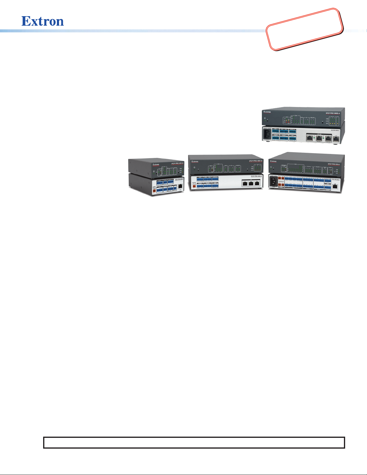
The Extron IPCPProQxi and xi Series IPLink® Pro Control Processors integrate Ethernet connection into AV systems to allow
users to remotely control, monitor, and troubleshoot AV equipment, including display devices and switchers. All models include an
embedded web server. Depending on the model, an IPCP control processor can include multiple bidirectional serial ports, relays,
IR/serial ports, digital I/O, flex I/O, switched 12 VDC power output ports, a volume control port, or contact input ports for use in
applications that require control and monitoring of multiple devices within a large-scale AV system.
All models include an Extron eBUS port, which allows a variety of eBUS devices to be connected
to a single control processor. eBUS devices include an array of button panels as well as
power and signal hubs. eBUS devices are automatically recognized by the control
processor and can be added or removed at any time.
In this guide these products are referred to as the “IPCP,” “IPCP Pro Q xi,” “IPCPProxi,”
or “control processor.” The xi models feature LAN ports. Q xi models feature both LAN
and AVLAN ports. AVLAN ports provide a secure, dedicated network for the connection
and isolation of AV devices.
This guide provides instructions for
an experienced installer to install a
control processor and to create a
basic configuration.
Use Extron Toolbelt software to
discover and manage the IPCPPro
control processor and other Extron
control products. Configure the control processor using Extron Global Configurator® software running in Global Configurator
Professional (GCProfessional) or Global Configurator Plus (GC Plus) mode, or program the control processor using Extron Global
Scripter®(GS). The IPCP integrates seamlessly with Extron GlobalViewer® Enterprise (GVE) software and Extron Control apps for
remote control applications. These control processors support multiple TouchLink®Pro touchpanel interfaces and Network Button
Panels (NBPs) over a standard Ethernet network. Global Configurator and other useful software applications are available at
www.extron.com.
product to the power source.
Setup Checklist: How to Proceed With Installation
Get Ready
Familiarize yourself with the features of the control processor (see Front Panel Features — Models Without AV LAN on
page4, Front Panel Features — Models With AV LAN on page5, Rear Panel Features — Models Without AV LAN
on page6, and Rear Panel Features — Models With AV LAN on page7) and of any TouchLinkPro touchpanels or
button panels that will be part of the system.
Download and install the latest version of the following:
• Toolbelt software — for discovering the control processor and other control products on the network, for managing
core settings, and for upgrading firmware when needed.
• Global Configurator (GC) software — for configuring the control system
• Global Scripter software — for programming the control processor (as an alternative to GC)
• PCS Product Configuration Software version 4.5 or higher — for setting the IP address for any IPCPProQxi model
with AV LAN ports if the ports are currently set to the default IP addresses
• GUI Designer software — for designing layouts for Extron TouchLinkPro touchpanels and third-party touch interfaces
• IPLinkPro device drivers — for use with GC, to make control of other AV devices possible
• IR Learner Pro software — for use with models that have IR receiver ports. Use this to create your own IR drivers using
the remote control of an AV device, if drivers are not already available from Extron
All are avail able from www.extron.com (see Locating Software, Firmware, and Driver Files on the Extron Website on page15).
Obtain network information for the unit from the network administrator. You also need the following details for each
Extron Pro series Ethernet-enabled device:
DHCP setting (on or off) Subnet mask Username
Device (IPCP Pro, TouchLinkPro, IPLPro, NBP) LAN IPaddress Gateway IP address Passwords
AVLAN IPaddress (for models with AV LAN)
NOTE: If DHCP is on, you do not need the IP addresses and subnet mask.
1
Page 2

IPCP Pro Q xi and xi Series • Setup Guide (Continued)
Write down the MAC address of each network interface on each IPLinkPro device to be used.
Obtain model names and setup information for devices the IPCP will control.
Each control processor comes with a factory-installed Secure Sockets Layer (SSL) security certificate. If you intend to install
a different SSL certificate, contact your IT department to obtain the certificate or for instructions on how to obtain one. See
“Secure Sockets Layer (SSL) Certificates” in the IPCPProQxi and xi Series User Guide for requirements and guidelines
regarding SSL certificates. IEEE 802.1X authentication is also supported once enabled (see “IEEE 802.1X Certificates” in the
IPCPProQxi and xi Series User Guide for details).
Mount and Cable All Devices
Mount the unit to a rack or furniture (see Mounting on the next page).
Cable devices to the control processor (see Cabling and Features on page 8).
Connect power cords and power on all the devices.
Set Up the Control Processor, Touchpanels, and Network Button Panels for Network Communication
Connect the PC that you will use for setup, the LAN (or AV LAN) port of the control processor, and the touchpanels or network
button panels to the same Ethernet network. For control processor LAN and AV LAN connections, see Control, Bidirectional —
LAN and AV LAN (Ethernet) on page9.
Start Toolbelt and use it to set the IP address, subnet, gateway IP address, DHCP status, and related settings. See the
flowchart in Network Communication Setup on the next page.
NOTES:
• When setting up DHCP during network configuration or if using a host name instead of an IP address, the user
must enter a qualified host name (Username.HostName.Domain). For example: somename.extron.com.
• A dedicated AV LAN safeguards AV systems from outside intrusion or interference by separating device control and
other network traffic from a corporate or campus network. To ensure that the control processor LAN and AV LAN
connections (ports) are connected to separate networks, the LAN and AV LAN IP address schemes must be on
different subnetworks.
Configure or Program the Control Processor, Touchpanels, and Network Button Panels
The most basic steps are outlined below in the recommended order.
NOTE: See the Toolbelt Help File, Global Configurator Help File, Global Scripter Help File, and GUI Designer Help File as
needed for step-by-step instructions and detailed information. The help file for GC includes an introduction to the software
and how to start a project and configuration.
If TouchLinkPro or third party touchpanels are part of the system, start and use GUI Designer to design, save, and build the
graphical user interface (GUI) layout for the touchpanels.
NOTE: To redeem (activate) a LinkLicense
®
, go to www.extron.com//llredeem and follow the online instructions.
Using GC, create a new GCProfessional or GCPlus project and configure the control processor and other IP Link Pro
devices. The configuration tells the control processor:
• How its ports function • What to monitor
• How to control other products • When to do things
• Which touchpanels to interact with • Whom to notify, how, and under what circumstances
Configure ports on the control processor:
Select device drivers and link them to each serial, IR/serial, or Ethernet port.
Select settings (serial protocol, relay behavior, digital I/O or flex I/O settings) as needed.
Add eBUS devices and set them up:
Ensure that the hardware address set on each device is distinct and matches the address used in the configuration.
Assign button functions as desired.
Add Network Button Panels (NBPs) and set them up. Assign button functions as desired.
Set up monitors, schedules, macros, and local variables.
Add touchpanels and set them up:
• Add the GUI configuration for each touchpanel to the GC project using Global Configurator.
• Assign any appropriate functions, monitors, or schedules to the touchpanels and their buttons.
2
Page 3
If not using GC Professional or GC Plus, use Global Scripter to program the control system as desired.
Program ports on the control processor:
• Program each serial, IR/serial, or Ethernet port.
• Program relay behavior, digital I/O, and flex I/O settings as needed.
Add eBUS devices and set them up:
• Ensure that the hardware address (eBUS ID) set on each device is distinct and matches the address programmed
for it in the IPCP.
• Program button functions as desired.
Add Network Button Panels and set them up. Program button functions as desired.
Add touchpanels and set them up:
• Upload the GUI configuration for the touchpanels to the project.
• Program functions, monitors, or schedules to the touchpanels and their buttons.
Save the GC or GS project.
Build and upload the system configuration to the control processor and other system devices.
Test and Troubleshoot
Test the system (see the IPCPProQxi and xi SeriesUser Guide for an outline of the system testing procedure).
Make adjustments to wiring or configuration as needed.
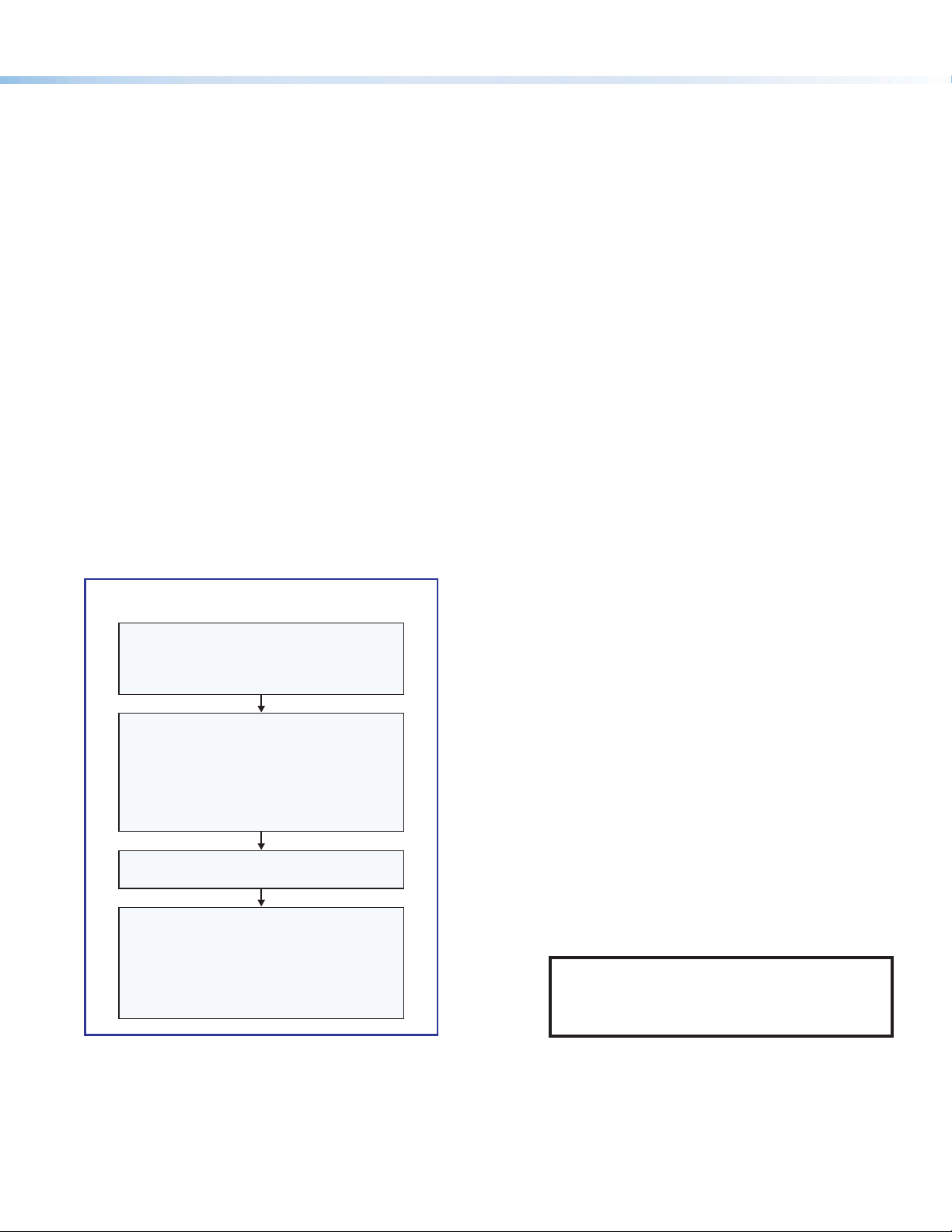
Network Communication Setup
Network setup is essential prior to configuration. Use the following flowchart as a guide to setting up the control processor for
network use.
Network Communication Setup
Connect the PC and the LAN port or AV LAN
port of the control processor to
the same network.
Apply power to all devices.
Open the Toolbelt software from within
Global Congurator (GC Professional or
GC Plus mode) or as the stand-alone
Toolbelt displays a list of all Extron control
devices connected to the network.
Using the MAC address, locate the desired
control processor in the list and select it.
(LAN, or LAN and AV LAN), use the Set IP
feature in Toolbelt or use the
Toolbelt
feature to enter the IP address and
subnet address, then congure other
network settings as needed.
application.
Start Device Discovery.
For each network interface
Manage > Network Settings tab
NOTE: If using 802.1X security, see the
Extron 802.1X Technology Reference Guide and
the Toolbelt Help file for additional details on
system setup.
Figure 1. Network Setup
Mounting
Securely mount the control processor and other devices and attach cables using the wiring section (see Cabling and Features
on page8) as a wiring guide. Optional 1U rack shelves and furniture mounting bracket kits are available for use with the control
processor. Read the instructions and UL guidelines that come with the rack shelf or mounting kit for installation procedures.
See the product-specific page at www.extron.com for a list of compatible accessories for mounting your control processor.
3
Page 4
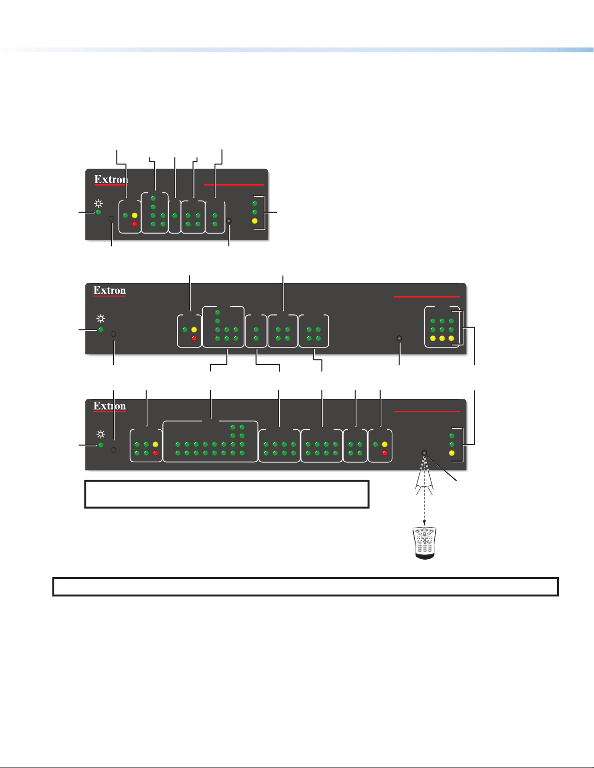
IPCP Pro Q xi and xi Series • Setup Guide (Continued)
COM
IR/
eBUS
Relay
Digital
Power
Power
Power
Panels and Locations of Features
Location and quantity of LEDs and corresponding connectors vary by model, but the functions and port wiring are identical
across models for each port type.
Front Panel Features — Models Without AV LAN
LED
LED
LED
Reset Button
(recessed)
Reset
Button
(recessed)
LEDs
R
R
R
Serial
eBUS
S
(Serial)
LEDs
RTS
CTS
LIMIT
Tx
Rx
OVER
COM
1
2
LEDs
IR/S
I/O
LEDs
I/O RELAYS
2
314
eBUS LEDs
eBUS
S
LIMIT
Switched
12 VDC
OVER
COM (Serial)
LEDs
SWITCHED
12 VDC
21
LIMIT
Tx
Rx
43 12345678
OVER
LEDs
IPCP PRO 250 xi
1000
1
LINK
IR
ACT
2
IR Receiver
COM
RTS
CTS
Tx
Rx
LEDs
COM
RTS
CTS
Tx
Rx
LAN/
Network
LEDs
Digital I/O LEDs
RELAYS
I/O
IR/S
2231
2
314
IR/Serial
LEDs
IR/SERIAL RELAYS FLEX
2134
5 678
21
314
Relay
LEDs
5 678213 4
Flex I/O
LEDs
I/O
2134
IPCP PRO 350 xi
1000
LINK
IR
ACT
IR Receiver
eBUS LEDs
IPCP PRO 550 xi
eBUS
S LIMIT
OVER
IR
LAN
12
1000
LINK
ACT
3
LAN/
Network
LEDs
NOTE: Numbers adjacent to LEDs correspond to the like-numbered
rear panel ports.
Figure 2. Front Panels: IPCPProxi Series Rack Mountable Models
NOTE: For full reset mode information, see the IPCPProQxi and xi Series User Guide.
4
15˚ 15˚
2–12"
(4–30 cm)
1 2 3
4 5 6
7 809
IR Receiver
IR Learning
Angle and
Distance
Page 5
Front Panel Features — Models With AV LAN
eBUS LEDs
Power
LIMIT
eBUS
OVER
Rx
CTS
RTS
Tx
ERROR
LINK
BUSY
COM
I/O
RELAYS
IR/S
12 121
COM
(Serial)
LEDs
IR/
Serial
LEDs
eBUS
LEDs
Relay
LEDs
Digital
I/O
LEDs
IPCP Pro xi AV LAN Embedded Control Processor
(within another device)
This section shows a front panel of a representative AV LAN model, not all models.
COM
LED
RTS
eBUS
LIMIT
OVER
CTS
Tx
Rx
R
LINK
BUSY
ERROR
IR/S
2231
I/O
314
RELAYS
2
21
314
IPCP PRO 360Q xi
AV LAN
12
1000
LINK
IR
ACT
LAN
3
Reset
Button
(recessed)
COM (Serial)
LEDs
Figure 3. IPCPPro360Q xi Front Panel
IR/Serial
LEDs
Digital I/O
LEDs
Relay
LEDs
IR
Receiver
AV LAN
LEDs
LAN
LEDs
5
Page 6

IPCP Pro Q xi and xi Series • Setup Guide (Continued)
EEEEEE
I
IPCP
IIIIII
JJJJJJ
FFFFFF
GGGGGG
LLLLLL
Rear Panel Features — Models Without AV LAN
COM 1
G
RTSCTS
Tx Rx
POWER
VOL
12V
1.0A MAX
AAAAAAAA
POWER
12V
1.0A MAX
AAAAAAAA
VCG
KKKKKKKK
Pro 350 xi
COM 1
IR/SERIAL
1SG2
F
F
E
GTx Rx
PCP Pro 550 xi
100-240V ~ 50-60Hz
DDDDDDDDEEEEEEEE
COM 2
Tx Rx
RELAYS
RTSCTS
SG
1 1 2 3 7
IIIIIIII
IPCP Pro 250 xi
DIGITAL I/O
3
G
12 4G
eBUS
-S+V +S G
C12
PWR OUT = 6W
JJJJJJJJ
DDDDDDDDE
COM 2 COM 3
GTx Rx GTx Rx
RELAYS
2143CC
G
G
2 1 2
IPCP PRO 250 xi
IR/S
SG
FFFFFFFFGGGGGGGG
I
I
DIGITAL I/O
1234G
eBUS
+V +S -S G
PWR OUT = 6W
J
J
MAC: 00-05-A6-XX-XX-XX
S/N: ####### E######
LAN
LLLLLLLL
MMMMMMMM
3 4
1 2
MMMMMMMM
00-05-A6-XX-XX-XX
MAC: 00-05-A6-XX-XX-XX
S/N: ####### E######
3 4
IPCP PRO 350 xi
LAN
123
L
L
JJJJJJJJ
PWR OUT = 12W
IPCP PRO 550 xi
00-05-A6-XX-XX-XX
MAC: 00-05-A6-XX-XX-XX
S/N: ####### E######
1.2A MAX
SWITCHED 12 VDC
40W MAX TOTAL
TxRx GTxRxG Tx Rx GTxRxG SGSG SGSG
3 4
4 5 6
TxRx GTxRxG Tx Rx GTxRxG
CCCCCCCCBBBBBBBB DDDDDDDD EEEEEEEE HHHHHHHH
RTSCTS
8
RTSCTS
5 6
SGSG SGSG
FFFFFFFF
Figure 4. IPCPProxi Control Processors —Rear Panels
Power input connector (external power supply)
A
Power input connector (internal power supply)
B
Switched 12 VDC power output ports
c
3-pole COM ports (RS-232-only)
D
5-pole COM ports (RS-232/RS-422/RS-485)
E
IR/serial output ports
F
Relay ports
G
7 8
+V +S -S G
eBUS
5 6
7 83214G
FLEX I/ORELAYSIR/SERIALCOM12 VDC
GGGGGGGG
Flex I/O ports (digital input/output or analog input)
H
Digital I/O ports (digital input/output)
I
eBUS ports
J
Volume control port
K
LAN connectors and LEDs (Ethernet)
L
MAC address label
M
LAN
LLLLLLLL
MMMMMMMM
6
Page 7

Rear Panel Features — Models With AV LAN
EEEEEE
IPCP Pro 255Q xi
IIIIII
FFFFFF
GGGGGG
HHHHHH
MMMMMM
JJJJJJ
LLLLLL
This section shows rear panels of some representative models with AV LAN.
IPCP Pro 360Q xi
100-240V ~ 1.5A MAX
IPCP Pro 555Q xi
100-240V ~ 50-60Hz
POWER
12V
0.8A MAX
AAAAAAAA
50-60 Hz
BBBBBBBB
1.2A MAX
DDDDDDDDEEEEEEEE
Tx Rx
COM 1
G
VOL
VCG
RTSCTS
COM 2
Tx Rx
RELAYS
DIGITAL I/O
G
12 4G
C12
PWR OUT = 6W
KKKKKKKK
E
GTx Rx
COM 2 COM 3
RTSCTS
SG
COM 1
IR/SERIAL
1SG2
FFFFFFFF GGGGGGGG
1 1 2 3 7
2 1 2
SWITCHED 12 VDC
40W MAX TOTAL
TxRx GTxRxG Tx Rx GTxRxG SGSG SGSG
3 4
4 5 6
TxRx GTxRxG Tx Rx GTxRxG
I
3
eBUS
-S+V +S G
JJJJJJJJ
RELAYS
2143CC
DDDDDDDDE
GTx Rx GTx Rx
IR/S
SG
FFFFFFFFGGGGGGGG
LLLLLLLLI
MAC: 00-05-A6-XX-XX-XX
S/N: ####### E######
MAC: 00-05-A6-XX-XX-XX
S/N: ####### E######
NNNNNNNN
IIIIIIII
DIGITAL I/O
1 234G
eBUS
+V +S -S G
PWR OUT = 6W
JJJJJJJJ
RTSCTS
8
RTSCTS
MMMMMMMM
LAN
AV
LAN
5 6
SGSG SGSG
00-05-A6-XX-XX-XX
MAC: 00-05-A6-XX-XX-XX
S/N: ####### E######
12
PWR
3 4
7 8
1 2
5 6
IPCP PRO 360Q xi
00-05-A6-XX-XX-XX
MAC: 00-05-A6-XX-XX-XX
IPCP AV LAN
PWR
S/N: ####### E######
3
AV LAN
PoE+ OUTPoE+ OUT
NNNNNNNN
J
J
PWR OUT = 12W
3 4
+V +S -S G
eBUS
7 83214G
FLEX I/ORELAYSIR/SERIALCOM12 VDC
IPCP LAN
LAN
LLLLLLLL
MAC: 00-05-A6-XX-XX-XX
S/N: ####### E######
MAC: 00-05-A6-XX-XX-XX
S/N: ####### E######
LAN
LAN
MMMMMMMM
M
M
L
L
AV
NNNNNNNN
MMMMMMMM
BBBBBBBB
DDDDDDDDCCCCCCCC F
EEEEEEEE
F G
Figure 5. IPCPProQxi Control Processors — Rear Panels
Power input connector (external power supply)
A
Power input connector (internal power supply)
B
Switched 12 VDC power output ports
c
3-pole COM ports (RS-232-only)
D
5-pole COM ports (RS-232/RS-422/RS-485)
E
IR/serial output ports
F
Relay ports
G
G H
Flex I/O ports (digital input/output or analog input)
H
Digital I/O ports (digital input/output)
I
eBUS ports
J
Volume control port
K
LAN connectors and LEDs (Ethernet)
L
MAC address labels
M
AV LAN connector and LEDs (Ethernet), some with PoE+
N
H
and PoE+ LEDs
7
Page 8

IPCP Pro Q xi and xi Series • Setup Guide (Continued)
Smooth
Rear Panel
Front Panel
Lights if total power drawn
Lights if total power drawn
Cabling and Features
Attach cables using the following wiring diagrams as a guide. Full details are available in the User Guide.
ATTENTION:
• Installation and service must be performed by experienced personnel.
• L’installation et l’entretien doivent être effectués par du personnel expérimenté.
Power Input — External
POWER
12V
x.xA MAX
Tie Wrap
Ridged
3/16"
(5 mm)
Max.
Power Input, External Power Supply
• Connect to
included 12 VDC
power supply.
– Return
+12 VDC input
Power Input — Internal
100-240V 50-60Hz
Power Input, Internal Power Supply
• Connect to 100 to
240 VAC.
1.2A MAX
• Front panel LED ( ) blinks during
boot-up and remains lit when the
IPCP is powered and operational.
To
Ridged
Smooth
AC
power
• Front panel LED ( ) blinks
during boot-up and remains lit
when the IPCP receives power.
R
Front Panel
Ground all devices.
External
12 VDC
Power Supply
NOTE:
Check the polarity of the power
supply before connecting it to the IPCP.
R
ATTENTION:
• Always use a power
supply supplied or
specified by Extron. Use
of an unauthorized power
supply voids all regulatory
compliance certification and
may cause damage to the
supply and the unit.
• Utilisez toujours une source
d’alimentation fournie ou
recommandée par Extron.
L’utilisation d’une source
d’alimentation non autorisée
annule toute certification de
conformité réglementaire et
peut endommager la source
d’alimentation et l’unité.
Power Output — Switched 12 VDC Power Output
1 2
SWITCHED 12 VDC
40W MAX TOTAL
3 4
Rear
Panel
12 VDC
3/16"
(5 mm)
Max.
Tie Wrap
Power Output — PoE+
The IPCPPro360Qxi can output PoE+ on AV LAN ports 2 and 3. For details, see the PoE+ output information on page 11.
8
Switched 12 VDC
Power Output
• Total output for all four ports
combined:
12 VDC, 40 watts (max.)
• Corresponding front panel
green LEDs ( ) light when
power is available at each port.
SWITCHED
12 VDC
21
LIMIT
OVER
43
Front
Panel
is 41-46 watts.
exceeds 47 watts.
Power output shuts off
until the user corrects the
overload.
Page 9

Control, Bidirectional — Serial (COM)
IR/SER
S
S
Y
Y
3
Rear
eceived.
Panels
(RS-232)
Serial (COM) Ports
Select protocol via software.
COM port default protocol:
• 9600 baud
• 8 data bits • 1 stop bit
• no parity • no ow control
COM 2 COM
G
GTx Rx Tx Rx
1 7
TxRx GTxRxG
or or
4
TxRx GTxRxG
COM 1
GTx Rx
RTSCTS
IAL
8
RTS
RTSCTS
CTS
5-pole COM
(RS-232, RS-422, RS-485)
NOTE: The 5-pole COM ports support both
3-pole COM
hardware and software ow control.
The 3-pole COM ports support software
ow control only.
To 5-pole
COM port
To 3-pole
COM port
Heat Shrink
Over Shield Wires
RTS
G Ground
Rx Receive
Tx
G
Ground
Rx
Receive
Tx
Transmit
Clear to send
Request to send
Transmit
Strip wires
3/16" (5 mm) max.
Heat Shrink
Receive (Rx)
Transmit (Tx)
Receive (Rx)
Transmit (Tx)
Projector, Panel
Display, PC, or Other
RS-232, RS-422, or
RS-485 Device
RS-232-
Controllable
Device
CTS
NOTE: If you use cable that has a drain wire, tie the drain wire to ground at both ends.
Front Panels
COM
Tx
Tx
Rx
Rx
12345678
1
RTS =
Request to Send
CTS = Clear to Send
Tx = Transmitting Data
Rx = Receiving Data
RTS
CTS
Tx
Rx
5-pole COM Pin Configurations
RS-232
Tx
Rx
Ground
RTS
CTS
RS-422
Tx-
Rx-
Ground
Tx+
Rx+
tied together)
tied together)
Pin
1 (Tx)
2 (Rx)
3 (G)
4 (RTS)
5 (CTS)
TIP:
STP 20-2P
cable, shown
at left, is
recommended
7/8"
(22 mm)
3/16"
(5 mm)
Max.
for these
Heat Shrink
on Outer
Jacket to
Inner
Conductor
Transition
connections.
For best
results,
insulate the
common or
drain wires
Extron
STP 20-2P Cable
using heat
shrink.
Control, Bidirectional — LAN and AV LAN (Ethernet)
Default port IP addresses and recommended connections vary depending on whether or not the IPCP model includes AV LAN
ports.
RTS
CTS
Tx
Rx
COM
231
RS-485
Data-
(pins 1 & 2
Ground
Data+
(pins 4 & 5
xi models — LAN ports
Insert
Twisted Pair Wires
RJ-45
Connector
Pins:
12345678
12
LAN
Activity
LED
Rear Panel,
Rack Mount
Models
Ethernet
TCP/IP
Network
PC
NOTE: The factory configured password
for this device has been set to the device
serial number. Passwords are case sensitive.
Performing a Reset to Factory Defaults reset
(see Reset Modes: a Brief Summary on
page14) sets the password to extron.
LAN (Ethernet) — Models Without AV LAN
Default protocol, public ports:
• IPCP IP address: 192.168.254.250
• Gateway IP address: 0.0.0.0
• Subnet mask: 255.255.255.0
• DNS address: 127.0.0.1
• DHCP client: off
or
LAN
Link
LED
• Link speed and duplex level: autodetected
• Data rates: 10/100/1000Base-T
NOTE: IPCPs with more than one LAN port function as
multiport, unmanaged network switches so you can
connect additional devices to the same network.
Default login
credentials:
• Username:
admin or
user
• Password:
extron
Front Panel,
Rack Mount
Models
1000
LINK
ACT
LAN
123
1000 Mbps
Connection
Network is
active.
Data is being
sent/r
9
Page 10

IPCP Pro Q xi and xi Series • Setup Guide (Continued)
A
2
3
A
S/
E######
#
2
3
OUT
A L
AN
S/
#
###### ##
#
###
-
0
X
X
N
eceived.
N
6-
XX-XX-XX-X
X
S/
E######
#
00
--A6-
YY
S/
#
00-05-A6-XX-XX-XX
Qxi models — LAN ports
Rear
Panels
PC
Corporate
TCP/IP
Network
00
5-A6-XX-XX-
-05-A6-XX-X
-XX
N:
E###
1
PoE+
IPCP AV LA
Ethernet
RJ-45
Connector
00-05-A6-XX-XX-XX
MAC: 00-05-A6-YY-YY-YY
S/N: ####### E######
oE+ OT
Insert Twisted
Pair Wires
Pins:
12345678
IPCP LAN
LAN
Activity
LED
or
Ethernet
PC
Corporate
TCP/IP
Network
MAC: 00-05-A6-XX-XX-XX
S/N: ####### E######
MAC: 00-0-A6-Y-
N: #######
LAN (Ethernet) —
IPCP Pro Q xi Models
Default protocol, LAN
ports:
• LAN IP address:
192.168.253.250
• Gateway IP address:
0.0.0.0
• Subnet mask:
255.255.255.0
Link
LED
LAN
N
##
• DNS address: 127.0.0.1
• DHCP client: off
• Link speed and duplex
level: autodetected
• Data rates:
10/100/1000Base-T
Default login
credentials:
• Username:
admin or user
• Password: extron
Front
Panels
1000
LINK
ACT
V LAN
LAN
1
1000 Mbps
Connection
Network is
active.
Data is being
sent/r
NOTES:
• IPCPs with more than one LAN or AV LAN port function as multiport, unmanaged network switches so you can connect additional
devices to the same network.
• The factory congured passwords for this device have been set to the device serial number. Passwords are case sensitive. Performing
a Reset to Factory Defaults reset (see Reset Modes: a Brief Summary on page ) sets the passwords to extron.
Reset Modes: a Brief Summary on page14
Qxi models — AVLAN ports
Ethernet
Insert Twisted
Pair Wires
RJ-45
Connector
Pins:
12345678
00-05-A6-XX-XX-XX
10
MAC: 00-05-A6-XX-XX-XX
S/N: ####### E######
NOTE: IPCPs with more than one LAN or AV LAN
NOTES:
port function as multiport, unmanaged network
• IPCPs with more than one LAN or AV LAN port
switches so you can connect additional
function as multiport, unmanaged network
devices to the same network.
switches so you can connect additional devices
to the same network.
• The factory congured passwords for this device
have been set to the device serial number.
Passwords are case sensitive. Performing a
Reset to Factory Defaults reset (see Reset
Modes: a Brief Summary on page14
Modes: a Brief Summary on page) sets the
passwords to extron.
IPCP AV LAN
AV LAN
21
PWR
PoE+ OUT PoE+ OUT
AV
Network
PWR
AC:
N: ####### E#####
3
PC
PC
AV
Network
Ethernet
Rear
Panels
MAC: 00-0-A
N: #######
##
-YY-
PCP LAN
LAN
or
Activity
LED
MAC: 00-05-A6-YY-YY-YY
S/N: ####### E######
AV
LAN
Link
LED
AV LAN (Ethernet)
Default protocol,
AV LAN:
• IP address:
192.168.254.250
• Subnet mask:
255.255.255.0
• DNS address: 127.0.0.1
• DHCP client: off
(disabled)
• DHCP server off
(disabled)
• Link speed and duplex
level: autodetected
• Data rates:
10/100/1000Base-T
Default login
credentials:
• Username:
admin or user
• Password: extron
Front
Panels
1000
LINK
ACT
AV LAN
12
A
3
1000 Mbps
Connection
Network is
active.
Data is being
sent/received.
AV LAN DHCP Server
The AV LAN DHCP Server is disabled by default. It can be enabled to dynamically assign
Reset
IP addresses to DHCP clients on the AV LAN.
Default protocol, AV LAN when
DHCP server is enabled:
• DHCP server IP address: 192.168.254.1
• Subnet mask: 255.255.255.0
• DNS address: 192.168.254.1
• DHCP dynamic address range for client
devices: 192.168.254.100 -
192.168.254.149
• Maximum served addresses when
DHCP server is enabled: 50
• DHCP client address lease time: 24 hours.
To use DHCP in the AV LAN:
1. Using Toolbelt, enable the DHCP server
for the AV LAN within the control
processor (see the software or
programming help le for details).
2. Enable DHCP on each client AV device
3. Connect client AV devices to the AV LAN.
(see the user guide for each product).
Page 11

PoE+ output: The IPCPPro360Qxi offers Power over Ethernet+ (PoE+) output on AV LAN ports 2 and 3.
Two Single IR Emitters
Source Device
Relay 1
R
PoE+ OUT
S/N: ####### E######
These RJ-45 connectors, labeled “PoE+ Out,” can output a maximum of 30watts per port.
The corresponding PowerLED lights when the port provides power. PoE+ ports can be monitored for status
and power consumption, and power output can be scheduled.
For details, see the IPCP Pro Qxi and xi Series User Guide and the Global Configurator Help File.
ATTENTION:
• Power over Ethernet (PoE) is intended for indoor use only. It is to be connected only to networks or circuits that are not
routed to the outside plant or building.
• L’alimentation via Ethernet (PoE) est destinée à une utilisation en intérieur uniquement. Elle doit être connectée
seulement à des réseaux ou des circuits qui ne sont pas routés au réseau ou au bâtiment extérieur.
PW
All models (with or without AV LAN)
MAC address: Each network interface of the control processor is assigned a unique
user hardware ID number (MAC address) (for example, 00-05-A6-05-1C-A0). You may need this
address during control processor configuration. A label that indicates the MAC address is located
on the rear or side panel of the unit.
Control, Unidirectional — IR/Serial
IR/Serial Ports
Output options:
• IR (30 kHz to 300 kHz,
with or without carrier signals)
• Unidirectional RS-232
Ground
IR Output Signal
(-)
(+)
(-)
(-)
(+)
(+)
To a Projector,
Panel Display, or the
Wired IR Remote or
RS-232 Port of a
Rear Panels Front Panels
1 2
IR/SERIAL
1SG2
SG
IR or RS-232
Output
Ground
or or
SGSG SGSG
SGSG SGSG
5 6
IR/SERIAL
3 4
7 8
or
Unidirectional
IR
G
S
00-05-A6-XX-XX-XX
MAC: 00-05-A6-XX-XX-XX
S/N: ####### E######
MAC: 00-05-A6-XX-XX-XX
IR/S
1
2
IR/Serial LEDs
Light when signals are transmitted
on the corresponding IR/serial port.
To the IR Receiver of a
Projector, Display, or
Source Device
MAC
Address
IR/SERIAL
2134
5678
Control, Unidirectional — Relays
Rear Panels
1 2
5 6
RELAYS
3 4
7 8
To Room
Control
Equipment
All relays
are
normally
open.
or
Open (1)
Normally
RELAYS
2143CC
Open (2)
Normally
Common
Common
Common
Relay 2
• Connect devices for contact control.
Relays
• Do not exceed a total of 24V at 1A for each port.
Normally
To Room
Control
Equipment
Open
21C
Closed
21C
Front Panels
RELAYS
2134
5678
Relay LEDs
Light when the corresponding relays
are activated (tied to GND, closed).
11
Page 12

IPCP Pro Q xi and xi Series • Setup Guide (Continued)
1
Device 1
Control, Unidirectional — Flex I/O or Digital I/O
Rear Panel Front Panel
DIGITAL I/O
1 234G
3214G
FLEX I/O
Heat
Shrink
Over
Shield
Wires
G
4
3
2
Switch,
Sensor
Ground
Wire
Nut
Device 4
Device 3
Device 2
Digital I/O (digital input/output)
Congure each port as a digital input or output,
with or without +5 VDC pull-up.
Use these ports to:
• Monitor or trigger events and functions (toggle relays,
issue commands, send e-mail), once congured.
• Power LEDs or other devices that accept a
TTL signal.
Flex I/O (digital input/output or analog input)
Congure each port as an analog input or as a digital
input or output with or without +5 VDC pull-up.
Share the same ground among
I/O connections.
(Switches, sensors,
LEDs, relays, or
similar items)
I/O
2
314
FLEX
I/O
21
34
Digital I/O
LEDs
Light when the
corresponding
ports are active.
Flex I/O LEDs
Light when the
corresponding
ports are active.
Control — eBUS
eBUS
+V +S -S G
PWR OUT = 6W
Rear Panels,
Rack Mount Models
PWR OUT = 12W
+V +S -S G
eBUS
Drain Wires
+V
+12 VDC
+S
+ Signal
-S
- Signal
G
Ground
eBUS Link LED (green)
Lights steadily and remains lit
when the unit detects connected
eBUS devices, there are no ID
conicts, and eBUS rmware is
not currently being synchronized.
eBUS Busy LED (amber)
Blinks while eBUS rmware is
being synchronized.
eBUS Error LED (red)
Blinks if the unit detects an
eBUS ID conict.
eBUS Accessory Port
Connect the rst eBUS device to this port, then connect other
eBUS devices and accessories to that device in the desired
topology (daisy chain, star, or combination).
• Wire the connectors the same at both ends for every eBUS
device.
• See the eBUS Technology Reference Guide for the
recommended distance from the control processor to the
last eBUS device and maximum quantity of devices per
control processor.
• The IPCP Pro can provide power to the button panel devices.
eBUS port
on an
eBUS device
(button
panel or
similar
device)
DISPLAY
OFF
ON
VOLUME
PC
VIDEO
VOLUME
MUTE
LAPTOP
DOC CAM
PC
DVD
VIDEO
eBUS
LINK
LIMIT
BUSY
ERROR
OVER
Front Panels,
Rack Mount Models
eBUS
S LIMIT
OVER
eBUS Limit LED
(amber)
Lights steadily and
remains lit while the
eBUS port uses the
maximum threshold
power.
eBUS Overload LED
(red)
Lights steadily when the
eBUS port exceeds
maximum threshold
power usage and enters
the fault state.
During this fault state,
eBUS port power is
shut down until the
power usage falls back
below the threshold.
The Over LED remains
lit during the fault state.
eBUS Status LED (green)
LED is not lit — This indicates one of the following
conditions:
• No power is present.
• No eBUS devices are detected.
LED is blinking fast — An eBUS ID conict has
occurred: two devices have the same bus ID number.
LED is blinking slowly — A rmware update is in
progress: the control processor is synchronizing
rmware of the eBUS panel(s).
LED is lit steadily — Power is present with conrmed
communication and there are no eBUS ID conicts
in the entire system.
12
Page 13

EBDB MINI
Reference voltage
V
Rear Panel
(or use
an EBDB
10-port hub)
eBUS DISTRIBUTION HUB
+
V G-S+S+V G-S+S+V G-S+S
• Connect up to four (4) eBUS devices to the
eBUS Connections
eBUS distribution hub (EBDB MINI).
• Wire the connectors the same at both ends.
ATTENTION:
• Do NOT connect the power pin to
any device that is already powered
by the IPCP control process or or
by a n additional power s uppl y.
• NE connectez PAS la broche
d'alimentation à un appareil déjà
alimenté par le processeur de
contrôle IPCP ou par une autre
source d'alimentation.
Control — Volume
Rear Panel
VOL
VCG
Ground (Gnd)
G
Control voltage (variable output to amp from IPCP Pro) – This signal controls the amp volume.
C
Reference voltage input (from amplier) – This allows the IPCP Pro to detect when the amp is present.
V
Reference
voltage: ≤10 VDC
VCG
Control voltage output:
0 - 10 VDC
X
Powered
eBUS
device(s)
G-S+S
G-S+S
G-S+S
+V
G-S+S
+V
+12 VDC
+V
+S
+ Signal
-
S
-
Signal
G
Ground
IPCP
Rear Panel
Tie drain wires to ground.
Volume Control
This port can be used to control the volume and mute or
unmute the audio for Extron half rack width audio ampliers.
• Connect to an Extron audio amplier to permit volume
control via touchpanel controls, macros, or schedules.
• Do not exceed 10 VDC input voltage.
Congure the maximum and minimum voltage limits. Set
Soft Start mode off or on (default). Soft Start mode allows
volume to gradually increase from mute to the previous level
after muting or power-on to prevent loud audio bursts.
eBUS
PWR OUT = 6W
+V
3/16" (5 mm) Max.
-S+V +S G
G-S+S
+
V
+
S G
–
S
Tie drain wires to ground.
NOTE:
Use shielded
cable and place the
control processor as
close as possible to
the amplier to avoid
picking up background
noise via the cable.
Ideal cable length is
six feet (1.8 m) or less.
eBUS port on an
EBP or other
eBUS device
Example:
Connecting to
Extron Amplifiers
VOL
VCG
IPCP Pro
Rear
Panel
Ground
G
Control voltage
C
XPA 1002
10V 50mA
GCV
G
STANDBY
MPA 401 Series
REMOTE
10V 50mA
GCV
GCV
10V 50mA
V or 10V G or
MPA 181T,
MP 101 Series
REMOTE
10V
VOL/MUTE
MPA 152MPA 152 Plus
REMOTE
10V 50mA
C or
VOL/MUTE
VOL/MUTE
NOTE: When audio mute is active,
the control processor sets output
voltage to
0 VDC, even if the
voltage range (minimum and
maximum voltage limits) has been
set to levels above zero, such as
2 V to 8 V.
13
Page 14

IPCP Pro Q xi and xi Series • Setup Guide (Continued)
Reset Modes: a Brief Summary
The IP Link Pro control processors offer the following reset modes:
• Run Factory Boot Code: Press and hold the front panel Reset button while applying power to the unit. Keep holding the
button down until the Power LED blinks twice, or for 6 seconds, then release the button. The
LED blinks slowly during bootup. The control processor runs the factory boot code (rather than
full firmware). Upload new firmware to the unit (see “Updating the Firmware” in the user guide
for details).
• Use this mode to temporarily boot up the unit running only the factory boot code, then
install the desired firmware.
• Use this in the event that a firmware update has failed or if incompatibility issues arise with
user-loaded firmware.
NOTES:
• Do not continue to operate the control processor using only the factory boot code.
The unit requires a full firmware package in order to be fully operational. If you want
to use the firmware version with which the unit shipped, you must upload that version
again (see the Global Configurator Help File or Toolbelt Help File for firmware upload
instructions).
• To return the unit to the firmware version that was running prior to the reset, cycle
power to the unit instead of installing new firmware.
• Project Recovery: See the IPCP Pro Qxi and xi Series User Guide for instructions. Use this mode to recover the
project in the event of a lost user name and password.
• Run/Stop Program: Hold down the Reset button for about 3 seconds, until the Power LED blinks once. Release
and press the Reset button momentarily (for <1second) within 1second. (Nothing happens
if the momentary press does not occur within 1second.) The LED blinks 2 times if scripts and
systems are starting. The LED blinks 3 times if they are stopping. This mode allows you to
restart any programs stopped by an IP settings reset.
• Toggle DHCP Client: Press the Reset button five times (consecutively). Release the button. Do not press the button
within 3seconds following the fifth press. Use this mode to enable or disable the DHCP client
for the LAN port.
• The Reset LED blinks 6 times if the DHCP client is enabled.
• The Reset LED blinks 3 times if the DHCP client is disabled.
NOTES:
• By default DHCP is off for the LAN port and the unit uses a static IP address.
• If DHCP has been enabled, when you disable DHCP, the unit reverts to using the previously-
set static IPaddress.
• Reset All IP Settings: Press and hold the front panel Reset button until the Power LED blinks once at 3 seconds and
twice at 6 seconds. Release and momentarily press the Reset button within 1 second. The
LED blinks 3 times in quick succession upon successful reset.
Use this mode to reset all network settings to factory default values without affecting
user-loaded files. This reset mode also stops any running programs
authentication.
turning DHCP off.
Lastly, this mode resets the settings for both LAN and AV LAN ports, including
and disables 802.1X
• Reset to Factory Defaults: Press and hold the front panel Reset button for 9 secondsuntil the Power LED blinks once
at 3 seconds, twice at 6 seconds, and thrice at 9 seconds. Release and momentarily press
the Reset button within 1 second. The
successful reset.
Use this mode to return the control processor to factory default settings. This mode also
deletes all user-loaded files and configurations
in the event logs table. User-loaded digital certificates are deleted. The unit continues to run the userloaded firmware.
For detailed information on each mode and its use, see the IPCP Pro Qxi and xi Series User Guide at www.extron.com.
Power LED blinks 4 times in quick succession upon
(except LinkLicense files), and it clears messages
14
Page 15

Resources
Obtaining Control Drivers
Extron provides an extensive selection of device drivers available on the Extron website. If the system requires a control driver
that is not already available, you have additional options:
• Request a new serial (RS-232) or Ethernet driver from Extron.
• Create your own custom IR device driver using IRLearnerPro software. Follow the directions in the IRLearnerPro Help File
to create a driver by using the remote control for that device and the IR receiver port on the front panel of the IPCP.
Obtaining Instructions, Information, and Assistance
A checklist of basic setup steps is provided at the beginning of this guide. For additional information see the help files and the
IPCPProQxi and xi Series User Guide, available at www.extron.com.
If you have questions during installation and setup, call the ExtronS3 Sales & Technical Support Hotline or the ExtronS3
Control Systems Support Hotline (1.800.633.9877).
Locating Software, Firmware, and Driver Files on the Extron Website
There are three main ways to find software, firmware, and device drivers within www.extron.com:
• Via links from the web page for the specific product
• Via the Download page (Click on the Download tab at the top of any page within www.extron.com.)
• Via links from search results
NOTES:
• For some software you have the option to click the Download Now button to begin downloading the software file. For other
software there is a link for contacting an Extron support representative who can provide you access to the latest version.
To obtain Extron control product software, you must have an Extron Insider account. Extron provides training to our
customers on how to use the software. Access to the full features of Global Configurator Professional is available to
those who successfully complete Extron Control Professional Certification.
• IPLinkPro Series RS-232 and Ethernet drivers are required. You must use serial and Ethernet drivers
developed specifically for the IPLinkPro platform. With the exception of IR device drivers, drivers used for the
previous generation IPLink (non-Pro) control processors are not compatible.
15
Page 16

IPCP Pro Q xi and xi Series • Setup Guide (Continued)
Overall Configuration Procedure for the Control Processor
Within Global Configurator
(GC Professional or
GC Plus mode):
Create a new GC Professional or GC Plus project
No Yes
Configure the IP settings
of the control processor,
NBP network button panels, and
TouchLink Pro touchpanels.
If desired or required, use
Toolbelt or other software to congure
security settings for 802.1X, SSL.
Upload security certicates, private keys.
and add the control processor to it.
Will
TouchLink Pro or
third party touchpanels or
other user interfaces
be used?
Create GUI layouts for the
touchpanels or other interfaces:
1. Start GUI Designer.
2. Create GUI layout designs for each
TouchLink Pro, third party
touchpanel (with a TouchLink
Interface), or a computer or
mobile device (with LinkLicense).
3. Save and build the GUI layout le.
Or...
Download existing GUI layouts
from identical touchpanels.
See Network
Communication Setup
Communication Setup
Network
on page3.
Congure ports on the
control processor.
Create monitors, schedules, timers,
macros, and local variables.
Add touchpanels, other interfaces, or
button panels (if used) to the project.
Import GUI layouts and congure the
touchpanels or other interfaces.
Save the project.
Build and upload the conguration to
the control processor.
Test the system, make adjustments,
nalize conguration.
Figure 6. Overall Configuration Steps
For information on safety guidelines, regulatory compliances, EMI/EMF compatibility, accessibility, and related topics, see the
Extron Safety and Regulatory Compliance Guide on the Extron website.
16
© 2021 - Extron All rights reserved. www.extron.com
All trademarks mentioned are the property of their respective owners.
Worldwide Headquarters: Extron USA West, 1025 E. Ball Road, Anaheim, CA 92805, 800.633.9876
68-3496-50
Rev. A
02 21
 Loading...