

Page 1
IMPORTANT:
IMPORTANT:
Go to www.extron.com for the complete
user guide, installation instructions, and
specifications before connecting the
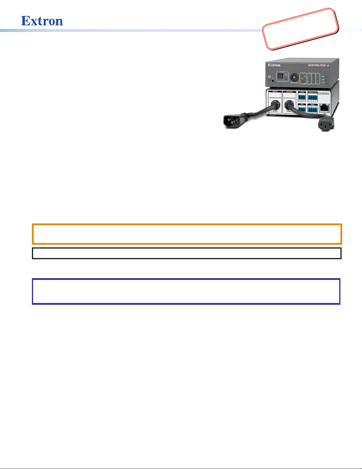
IPCP Pro PCS1xi • Setup Guide
The Extron IPCPProPCS1xi Power and Device Control Processor integrates Ethernet
connection into AV systems to allow users to remotely control and monitor AV
equipment, including display devices and switchers. The IPCPProPCS1xi features a
controllable, 100-240 VAC, 50-60 Hz, AC power outlet for remote power management of
a connected device. A 10amp circuit breaker provides overcurrent protection.
The AC power button, located on the front panel, allows manual control of
the AC power output port. A front panel security lockout mode (executive
mode) can be used to disable the button if the unit is installed in an
unsecured environment where access is undesirable.
The IPCPProPCS1xi includes an embedded web server, a bidirectional
serial port, an IR/serial port, digital I/O ports, and a LAN port for use in
applications that require control and monitoring of multiple devices within an AV system. It also includes an Extron eBUS® port,
which allows a variety of eBUS devices to be connected to a single control processor. eBUS devices include an array of button
panels as well as power and signal hubs. eBUS devices are automatically recognized by the control processor and can be added
or removed at any time.
To discover and manage the IPCP and other Extron control products, use Extron Toolbelt® software. Configure the control
processor using Extron Global Configurator® software (Global Configurator Professional [GCProfessional] or Global Configurator
Plus [GC Plus]), or program the control processor using Extron Global Scripter®(GS). The IPCP integrates seamlessly with Extron
GlobalViewer® Enterprise (GVE) software and Extron Control apps for remote control applications. These control processors
support multiple TouchLink®Pro touchpanel interfaces and Network Button Panels (NBPs) over a standard Ethernet network. The
software applications are available at www.extron.com.
Users can view AC current value and circuit breaker status and access Extron Control from the IPCP embedded web page.
This guide provides instructions for an experienced installer to install the control processor and to create a basic configuration.
product to the power source.
CAUTION: This product is intended for indoor use only.
ATTENTION : Ce produit est exclusivement adapté à un usage intérieur.
NOTE: The IPCPProPCS1xi is intended to be used with Extron Electronics products only.
Setup Checklist: How to Proceed With Installation
ATTENTION:
• Installation and service must be performed by experienced personnel.
• L’installation et l’entretien doivent être effectués par du personnel expérimenté.
Get Ready
Familiarize yourself with the features of the control processor (see Front Panel Features on page4, Rear Panel
Features on page4) and of any TouchLinkPro touchpanels or button panels that will be part of the system.
Download and install the latest version of the following:
• Toolbelt software — for discovering the control processor and other control products on the network, for managing
core settings, and for upgrading firmware when needed.
• Global Configurator (GC) software — for configuring the control system
• Global Scripter software — for programming the control processor (as an alternative to GC)
• GUI Designer software — for designing layouts for Extron TouchLinkPro touchpanels and third party touch interfaces
• IPLinkPro device drivers — for use with GC, to make control of AV devices possible
All are avail able from www.extron.com (see Locating Software, Firmware, and Driver Files on the Extron Website on page9).
Obtain network information for the unit from the network administrator. You need the following details for each
Extron Pro series Ethernet-enabled device:
DHCP client setting (on or off) Subnet mask Username
Device (IPCP Pro, TouchLinkPro, IPLPro, NBP) LAN IPaddress Gateway IP address Passwords
Write down the MAC address of each IPLinkPro device to be used.
Obtain model names and setup information for devices the IPCP will control.
1
Page 2

IPCP Pro PCS1 xi • Setup Guide (Continued)
Each control processor comes with a factory-installed Secure Sockets Layer (SSL) security certificate. If you intend to install
a different SSL certificate, contact your IT department to obtain the certificate or for instructions on how to obtain one.
See “Secure Sockets Layer (SSL) Certificates” in the IPCPProSeries User Guide for requirements and guidelines regarding
SSL certificates. IEEE 802.1X authentication is also supported once enabled (see “IEEE 802.1X Certificates” in the
IPCPProQxi and xi Series User Guide for details).
Mount and Cable All Devices
Mount the unit to a rack or furniture (see Mounting on the next page).
Cable devices to the control processor (see Cabling and Features on page 5).
Connect power cords and power on all the devices.
Set Up the Control Processor, Touchpanels, and Network Button Panels for Network Communication
Connect the PC that you will use for setup, the LAN port of the control processor, and the touchpanels or network button
panels to the same Ethernet network. For control processor LAN connections, see Control, Bidirectional — LAN (Ethernet)
on page6.
Start Toolbelt and use it to set the IP address, subnet, gateway IP address, DHCP status, and related settings (see the
flowchart in Network Communication Setup on the next page).
NOTE: When setting up DHCP during network configuration or if using a host name instead of an IP address, the user
must enter a qualified host name (Username.HostName.Domain). For example: somename.extron.com.
Configure or Program the Control Processor, Touchpanels, and Network Button Panels
The most basic steps are outlined below in the recommended order.
NOTE: See the Toolbelt Help File, Global Configurator Help File, Global Scripter Help File, and GUI Designer Help File as
needed for step-by-step instructions and detailed information. The help file for GC includes an introduction to the software
and how to start a project and configuration.
If TouchLinkPro or third party touchpanels are part of the system, start and use GUI Designer to design, save, and build the
graphical user interface (GUI) layout for the touchpanels.
NOTE: To redeem (activate) a LinkLicense
®
, go to www.extron.com//llredeem and follow the online instructions.
Using GC, create a new GCProfessional or GCPlus project and configure the control processor and other IP Link Pro
devices. The configuration tells the control processor:
• How its ports function • What to monitor
• How to control other products • When to do things
• Which touchpanels to interact with • Whom to notify, how, and under what circumstances
Configure ports on the control processor:
Select device drivers and link them to each serial, IR/serial, or Ethernet port.
Select settings (serial protocol, digital I/O settings, AC output settings) as needed.
Add eBUS devices and set them up:
Ensure that the hardware address set on each device is distinct and matches the address used in the configuration.
Assign button functions as desired.
Add Network Button Panels (NBPs) and set them up. Assign button functions as desired.
Set up monitors, schedules, macros, and local variables.
Add touchpanels and set them up:
• Upload the GUI configuration for the touchpanels to the project within GC Professional or GC Plus.
• Assign any appropriate functions, monitors, or schedules to the touchpanels and their buttons.
If not using GC Professional or GC Plus, use Global Scripter to program the control system as desired.
Program ports on the control processor.
• Program each serial, IR/serial, or Ethernet port.
• Program digital I/O settings, AC output settings as needed.
Add eBUS devices and set them up:
• Ensure that the hardware address (eBUS ID) set on each device is distinct and matches the address programmed
for it in the IPCP.
• Program button functions as desired.
2
Page 3
Add Network Button Panels and set them up. Program button functions as desired.
Add touchpanels and set them up:
Upload the GUI configuration for the touchpanels to the project.
Program functions, monitors, or schedules to the touchpanels and their buttons.
Save the GC or GS project.
Build and upload the system configuration to the control processor and other system devices.
Test and Troubleshoot
Test the system (see the IPCPProQxi and xi Series User Guide for an outline of the system testing procedure).
Make adjustments to wiring or configuration as needed.
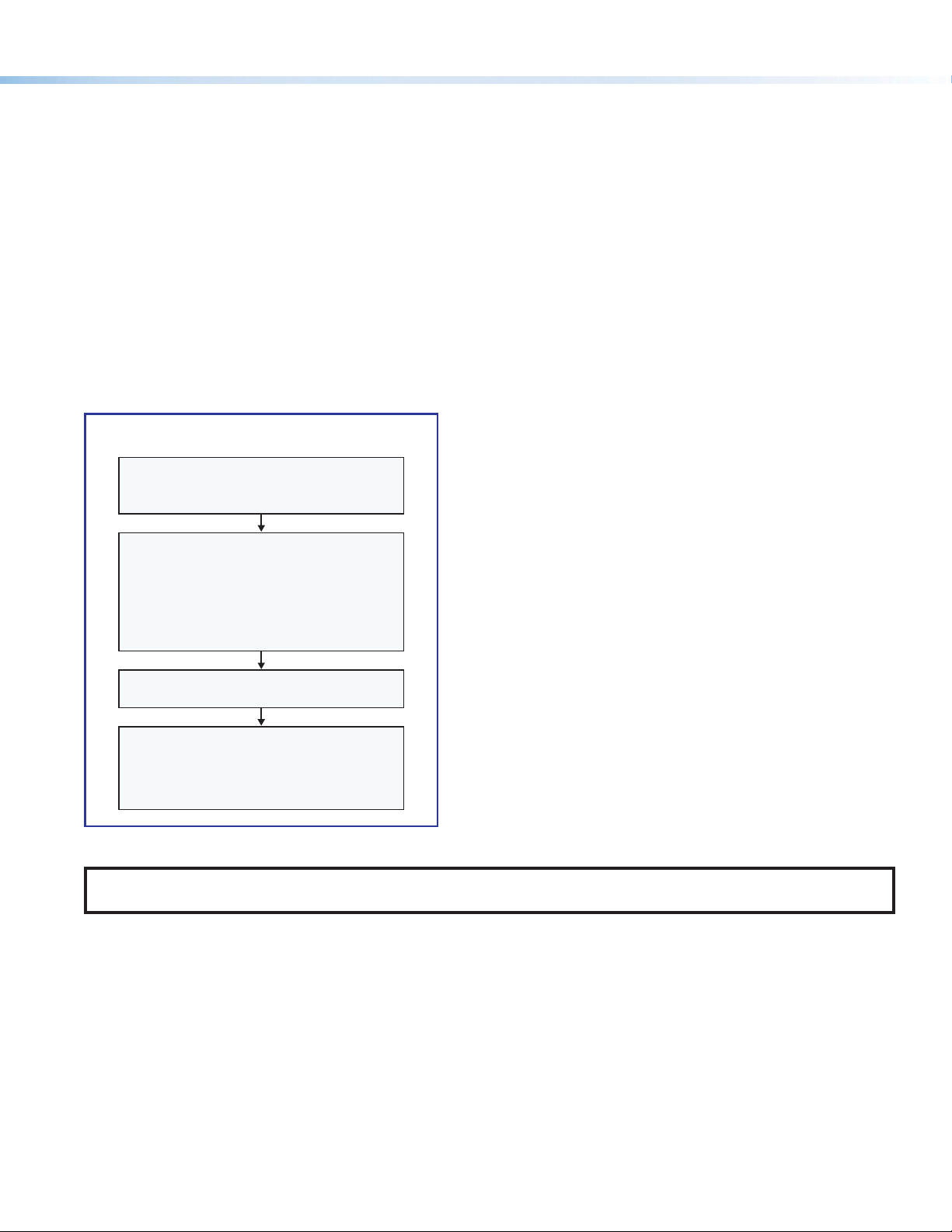
Network Communication Setup
Network setup is essential prior to configuration. Use the following flowchart as a guide to setting up the control processor for
network use.
Network Communication Setup
Connect the PC and the LAN port of the
control processor to the same network.
Apply power to all devices.
Open the Toolbelt software from within
Global Congurator (GC Professional or
GC Plus mode) or as the stand-alone
Toolbelt displays a list of all Extron control
devices connected to the network.
application.
Start Device Discovery.
Using the MAC address, locate the desired
control processor in the list and select it.
Use the Set IP feature in Toolbelt or use the
Toolbelt
Figure 1. Network Setup
Manage > Network Settings tab
feature to enter the IP address and
subnet address, then congure other
network settings as needed.
NOTE: If using 802.1X security, see the Extron 802.1X Technology Reference Guide and the Toolbelt Help file for additional
details on system setup.
Mounting
Securely mount the control processor and other devices and attach cables using the wiring section (see Cabling and Features
on page5) as a wiring guide. Optional 1U rack shelves and furniture mounting bracket kits are available for use with the control
processor. Read the instructions and UL guidelines that come with the rack shelf or mounting kit for installation procedures.
See the product-specific page at www.extron.com for a list of compatible accessories for mounting your control processor.
3
Page 4
IPCP Pro PCS1 xi • Setup Guide (Continued)
CCCCCCCC
AAAAAAAA BBBBBBBB
D
DDDDDDD
FFFFFFFFEEEEEEEE GGGGGGGG
H
HHHHHHH
COM (Serial) LEDs
Digital
I/O LEDs
Reset Button
and LED
Breaker
eBUS
Network
IR/
Serial
POWER
BREAKER
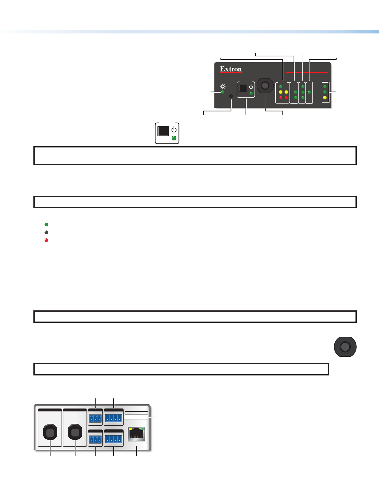
Panels and Locations of Features
Front Panel Features
LEDs
LED
See figure 2 at right for the front panel features and their
locations.
The LED indications are described and shown in Cabling
and Features (starting on the next page) paired with
descriptions of the corresponding ports. For reset button and
reset mode information, see the IPCPProSeries User Guide.
Power button (switch) and LED
The front panel power button (switch) provides
a convenient way to manually turn switched
AC power output on or off for the rear panel
O
T
10
S
S
E
R
P
BREAKER
Power
LED
(recessed)
POWER
R
AC Power Button
Figure 2. IPCP Pro PCS1xi Front Panel
IPCP PRO PCS1 xi
R
E
eBUS
S
E
L
T
LIMIT
B
E
OVER
Circuit
COM
Tx
Rx
I/O IR/S
1
2
3
1000
LINK
ACT
LAN/
LEDs
AC power output cable.
NOTE: The button is not a safety disconnect device. In case of an emergency, disconnect AC power from the power input
(appliance inlet) of the connected equipment.
The IPCPProPCS1xi can be configured (using Global Configurator or Global Scripter) to monitor the power output condition
and to alert users in the event of a power fault interruption. The IPCPProPCS1xi can be set up to monitor the circuit breaker and
also the current load at the switched AC power output port. The AC current value and circuit breaker status are shown in the IPCP
embedded web page. Power output can also be toggled on and off using a control in the embedded web page.
NOTE: The power output state setting persists after and is retained during a power cycle.
LED indications for power output state
• Lit green: power output is enabled.
• Off (dark): power output is disabled.
• Lit red: a fault condition is detected, and power output is disabled.
Front panel lockout (executive mode)
To prevent unauthorized use, this button can be locked (disabled) via a front panel lockout mode (executive mode) that can be
enabled or disabled by one of two methods:
• Using software, as part of the configuration or when programming actions, monitors or schedules
• Holding down the power button switch for 3 seconds
The power LED blinks three times to indicate the lockout mode has been enabled or disabled.
When the front panel is locked, if the Power button is pressed, the power LED blinks three times to indicate that the button is
locked, and the unit does not change power states as a result of the button press.
4
NOTE: The executive mode state (on or off) persists after and is retained during a power cycle.
Circuit breaker
The front panel features a 10 A rated circuit breaker. When a fault condition occurs, the breaker is triggered, which
stops power output. This condition can be monitored and the system can be configured (using available commands)
to send an alert e-mail or perform some other action. After you correct the cause of the overcurrent condition, press
the Breaker button to manually reset the circuit breaker.
NOTE: The circuit breaker and the Reset button are not affected by front panel lockout (executive mode) settings.
Rear Panel Features
Power input (attached cable) — Powers the IPCPProPCS1xi,
IPCP Pro PCS1 xi
COM
Tx Rx
IR/S
SG
G
PWR OUT = 6W
DIGITAL I/O
1 2 3 G
eBUS
-S+V +S G
INPUT
100-240V ~ 10A MAX
50-60Hz
100-240V ~ 10A MAX
OUTPUT
50-60Hz
Figure 3. IPCPProPCS1xi Rear Panel
IPCP PRO PCS1 xi
MAC: 00-05-A6-XX-XX-XX
S/N: ####### E######
LAN
A
next page
AC power output (attached cable) — Provides switched
B
(controlled) AC power output to another device, next page
3-pole COM port (RS-232-only), page 6
c
Digital I/O ports (digital input/output), page 7
D
IR/serial output port, page 6
E
eBUS port, page 7
F
LAN connector and LEDs (Ethernet), page 6
G
MAC address, page 6
H
O
R
T
E
10
S
10
E
S
T
S
E
R
P
Page 5
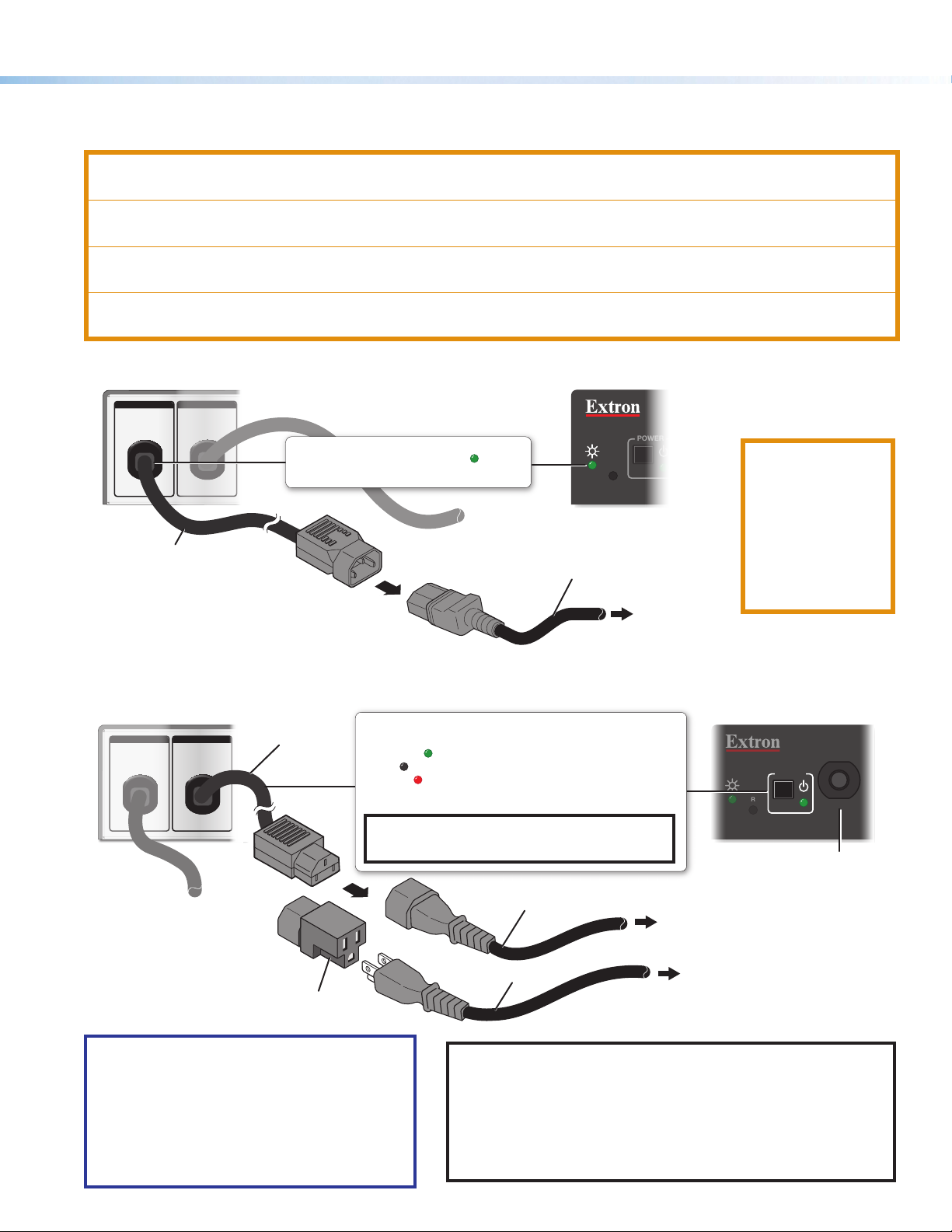
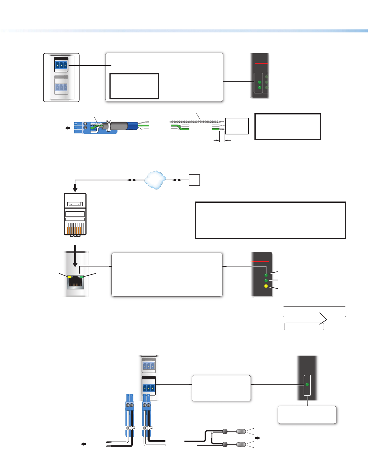
Cabling and Features
POWER
R
Attach cables using the following wiring diagrams as a guide. Full details are available in the IPCPProQxi and xi Series User Guide.
CAUTION:
ATTENTION :
• Total length of the power cord including the small pigtail shall not be less than 1.5m or more than 4.5m.
• La longueur totale du câble d’alimentation, cordon compris, ne doit pas être inférieure à 1,5 m ou supérieure à 4,5m.
• Always use the power cord provided with the unit.
• Veillez à toujours utiliser le câble d’alimentation fourni avec l’unité.
• Should you need to use a different power cord, consult Extron Electronics prior to using the cord.
• Si vous devez utiliser un autre câble d’alimentation, contactez Extron Electronics avant d’utiliser ce câble.
Power Input — Internal
INPUT
100-240V ~ 10A MAX
50-60Hz
Rear Panel
6 inch (152 mm)
IEC Input Cable
OUTPUT
100-240V ~ 10A MAX
50-60Hz
Power Input, Internal Power Supply
• Connect to
100 to 240 VAC.
• Front panel LED ( ) blinks
during boot-up and remains lit
when the IPCP receives power.
Power Output — Switched AC Power Output
Switched 100-240 VAC, 10 A (Max.) Power Output
• Front panel Power LED appears:
• Lit green ( ) when power output is enabled (unit outputs power)
• Off ( ) when power output is disabled (power output is off)
• Lit red ( ) when a power output overcurrent condition is detected
(the circuit breaker has been tripped) and power output is disabled.
• Front panel Power button controls power output availability.
NOTE: The front panel power switch is not a safety disconnect
device. In case of emergency, disconnect AC power from the
power input (appliance inlet) of the connected equipment.
or
INPUT
100-240V ~ 10A MAX
50-60Hz
Rear
Panel
OUTPUT
100-240V ~ 10A MAX
50-60Hz
6 inch (152 mm)
IEC Output Cable
NEMA 5-15R
Adapter
IEC Power Cord
IEC Power Cord
Edison Power Cord
R
Front Panel
To a 100 - 240 VAC
power source
(main power)
Power input port
on an AV device
(international)
Power input port
on an AV device
CAUTION: Always
disconnect the
product from the
wall plug.
ATTENTION:
Veillez à toujours
déconnecter le
produit de la
prise murale.
POWER
Front
Panel
(USA)
O
R
T
E
10
S
E
S
T
S
E
R
P
BREAKER
Circuit Breaker
(power output
overcurrent
protection)
ATTENTION:
• When using the NEMA5-15R receptacle
adapter, connect the equipment only to a
nominal 120VAC electrical supply source.
• Lorsque vous utilisez la prise de courant
NEMA5-15R, veillez à ne connecter le
dispositif qu’à une source d’alimentation
nominale de 120Vca.
NOTES:
• Within the United States of America use a power supply cord
with conductors that are a minimum diameter of 18 AWG.
• For international installations, use a power supply cord with
conductors that are a minimum of 1.0mm2.
• Make sure that the device being controlled can support an AC
power cycle.
5
Page 6
IPCP Pro PCS1 xi • Setup Guide (Continued)
S
G
/S
S
I/O
3/16" (5 mm) max.
Front Panel
Rear Panel
P
RJ-45
Connector
eceived.
G
TxR
CO
Rear Panel Front Panel
Two Single IR Emitters
Source Device
S/N: ####### E######
Control, Bidirectional — Serial (COM)
COM
Tx Rx
IR
3-pole COM
G
(RS-232)
NOTE: The 3-pole
COM port
supports software
Serial (COM) Port
Select protocol via software.
COM port default protocol:
• 9600 baud
• 8 data bits • 1 stop bit
• no parity • no ow control
IPCP
COM
Tx
Rx
1
2
3
ow control only.
To 3-pole
COM port
Heat Shrink
Over Shield Wires
G
Rx
Tx
Ground
Receive
Transmit
Heat Shrink
Receive (Rx)
Transmit (Tx)
Strip wires
RS-232-
Controllable
Device
NOTE:
Control, Bidirectional — LAN (Ethernet)
Insert Twisted
Rear
Panel
Activity
LED
Pins:
LAN
12345678
Pair Wires
Link
LED
Ethernet
Default protocol, public ports:
• IPCP IP address: 192.168.254.250
• Gateway IP address: 0.0.0.0
• Subnet mask: 255.255.255.0
• DNS address: 127.0.0.1
• DHCP client: off
• Link speed and duplex level: autodetected
• Data rates: 10/100/1000Base-T
The control processor is assigned a unique user hardware ID number (MAC address,
for example, 00-05-A6-05-1C-A0). You may need this address during control processor configuration.
A label that indicates the MAC address is located on the rear or side panel of the unit.
TCP/IP
Network
LAN (Ethernet)
PC
NOTE: The factory configured passwords for this device
have been set to the device serial number. Passwords
are case sensitive. Performing a Reset to Factory
Defaults reset (see Reset Modes: a Brief Summary on
page8) sets the passwords to extron.
Front Panel
RO PCS1 xi
Default login
credentials:
• Username:
admin or
user
• Password:
extron
1000
LINK
ACT
If you use cable that
has a drain wire, tie the
drain wire to ground at
both ends.
1000 Mbps
Connection
Network is
active.
Data is being
sent/r
00-05-A6-XX-XX-XX
MAC: 00-05-A6-XX-XX-XX
S/N: ####### E######
MAC: 00-05-A6-XX-XX-XX
MAC
Address
Control, Unidirectional — IR/Serial
To a Projector,
Panel Display, or the
Wired IR Remote or
RS-232 Port of a
6
IR or RS-232
Output
Ground
M
IR/S
SG
or
Unidirectional
IR
Output options:
• IR (30 kHz to 300 kHz,
• Unidirectional RS-232
Ground
G
IR Output Signal
S
IR/Serial Ports
with or without carrier signals)
(-)
(+)
(-)
(-)
(+)
(+)
To the IR Receiver of a
Projector, Display, or
IR/Serial LED
Lights when signals are
transmitted on the IR/serial port.
Source Device
IR/S
Page 7
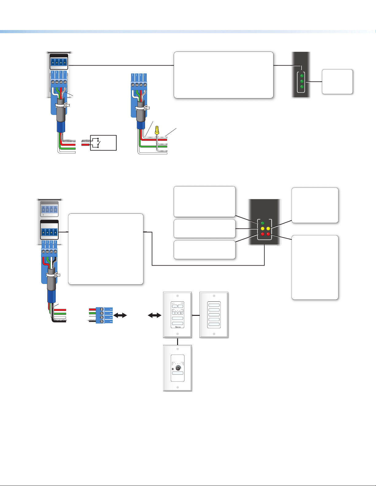
Control, Unidirectional — Digital I/O
P
W
-S+SG
BUS
eBUS
1
Device 1
3
G
DIGITAL I
/O
Rear Panel Front Panel
I/O
3
12 G
WR OUT = 6
Heat
Shrink
Over
Shield
Wires
G
3
2
Switch,
Sensor
Control — eBUS
Ground
Digital I/O (digital input/output)
Congure each port as a digital input or output,
with or without +5 VDC pull-up.
Use these ports to:
• Monitor or trigger events and functions (toggle relays,
issue commands, send e-mail), once congured.
• Power LEDs or other devices that accept a
TTL signal.
Wire
Nut
Share the same ground among
I/O connections.
Device 3
Device 2
(Switches, sensors,
LEDs, relays, or
similar items)
I/O
1
2
3
Digital I/O
LEDs
Light when the
corresponding
ports are active.
Rear Panel
eBUS
-S+V +S G
PWR OUT = 6W
eBUS Accessory Port
Connect the rst eBUS device to this
port, then connect other eBUS devices
and accessories to that device in the
desired topology (daisy chain, star, or
combination).
• Wire the connectors the same at
both ends for every eBUS device.
• See the eBUS Technology Reference
Guide for the recommended distance
from the control processor to the last
eBUS device and maximum quantity
of devices per control processor.
• The IPCP Pro can provide power to
the button panel devices.
Drain Wires
+V
+12 VDC
+S
+ Signal
-S
- Signal
G
Ground
eBUS port
on an
eBUS device
(button
panel or
similar
device)
eBUS Link LED (green)
Lights steadily and remains lit
when the unit detects connected
eBUS devices, there are no ID
conicts, and eBUS rmware is
not currently being synchronized.
eBUS Busy LED (amber)
Blinks while eBUS rmware is
being synchronized.
eBUS Error LED (red)
Blinks if the unit detects an
eBUS ID conict.
DISPLAY
OFF
ON
VOLUME
PC
VIDEO
VOLUME
LAPTOP
DOC CAM
PC
DVD
VIDEO
Front Panel
eBUS
L
B
E
LIMIT
OVER
eBUS Limit LED
(amber)
Lights steadily and
remains lit while the
eBUS port uses the
maximum threshold
power.
eBUS Overload LED
(red)
Lights steadily when the
eBUS port exceeds
maximum threshold
power usage and enters
the fault state.
During this fault state,
eBUS port power is
shut down until the
power usage falls back
below the threshold.
The Over LED remains
lit during the fault state.
MUTE
(Continued on the next page)
7
Page 8

IPCP Pro PCS1 xi • Setup Guide (Continued)
+
V
+
S
G
–
S
Tie drain wires to ground.
X
EBDB MINI
Rear Panel
(or use
an EBDB
10-port hub)
ATTENTION:
• Do NOT connect the power pin to
any device that is already powere d
by the IPCP Pro control processor
or by an addi ti onal power supply.
• NE connectez PAS la broche
d'alimentati on à un appa reil déjà
alimenté par le processeur de
contrôle IPCP Pro ou par une autre
eBUS DISTRIBUTION HUB
+
V G-S+S+V G-S+S+V G-S+S
X
G-S+S
• Connect up to four (4) eBUS devices to the
EBDB Mini eBUS Distribution Hub.
•Wire the connectors the same at both ends.
G-S+S
+V
G-S+S
+V
+V
+S
-
S
G
IPCP Pro
Rear Panel
+12 VDC
+ Signal
-
Signal
Ground
eBUS
PWR OUT = 6W
eBUS Connections
3/16" (5 mm) Max.
Tie drain wires to ground.
-S+V +S G
+
V
+
S
–
S
G
eBUS port on an
EBP or other
eBUS endpoint
device
source d'alimentation.
G-S+S
Powered
G-S+S
eBUS
device(s)
+V
Reset Modes: a Brief Summary
The IP Link Pro control processors offer the following reset modes:
• Run Factory Boot Code: Press and hold the front panel Reset button while applying power to the unit. Keep holding the
button down until the Power LED blinks twice, or for 6 seconds, then release the button. The
LED blinks slowly during bootup. The control processor runs the factory boot code (rather than
full firmware). Upload new firmware to the unit (see “Updating the Firmware” in the user guide
for details).
• Use this mode to temporarily boot up the unit running only the factory boot code, then
install the desired firmware.
• Use this in the event that a firmware update has failed or if incompatibility issues arise with
user-loaded firmware.
NOTES:
• Do not continue to operate the control processor using only the factory boot code.
The unit requires a full firmware package in order to be fully operational. If you want
to use the firmware version with which the unit shipped, you must upload that version
again (see the Global Configurator Help File or Toolbelt Help File for firmware upload
instructions).
• To return the unit to the firmware version that was running prior to the reset, cycle
power to the unit instead of installing new firmware.
• Project Recovery: See the IPCP Pro Qxi and xi Series User Guide for instructions. Use this mode to recover the
project in the event of a lost user name and password.
• Run/Stop Program: Hold down the Reset button for about 3 seconds, until the Power LED blinks once. Release
and press the Reset button momentarily (for <1second) within 1second. (Nothing happens
if the momentary press does not occur within 1second.) The LED blinks 2 times if scripts and
systems are starting. The LED blinks 3 times if they are stopping. This mode allows you to
• Toggle DHCP Client: Press the Reset button five times (consecutively). Release the button. Do not press the button
restart any programs stopped by an IP settings reset.
within 3seconds following the fifth press. Use this mode to enable or disable the DHCP client
for the LAN port.
• The Reset LED blinks 6 times if the DHCP client is enabled.
• The Reset LED blinks 3 times if the DHCP client is disabled.
NOTES:
• By default DHCP is off for the LAN port and the unit uses a static IP address.
• If DHCP has been enabled, when you disable DHCP, the unit reverts to using the previously-
set static IPaddress.
8
Page 9

• Reset All IP Settings: Press and hold the front panel Reset button until the Power LED blinks once at 3 seconds and
twice at 6 seconds. Release and momentarily press the Reset button within 1 second. The
LED blinks 3 times in quick succession upon successful reset.
Use this mode to reset all network settings to factory default values without affecting
user-loaded files. This reset mode also stops any running programs
authentication.
turning DHCP off.
Lastly, this mode resets the settings for both LAN and AV LAN ports, including
and disables 802.1X
• Reset to Factory Defaults: Press and hold the front panel Reset button for 9 secondsuntil the Power LED blinks once
at 3 seconds, twice at 6 seconds, and thrice at 9 seconds. Release and momentarily press
the Reset button within 1 second. The
successful reset.
Use this mode to return the control processor to factory default settings. This mode also
deletes all user-loaded files and configurations
in the event logs table. User-loaded digital certificates are deleted. The unit continues to run the userloaded firmware.
For detailed information on each mode and its use, see the IPCP Pro Qxi and xi Series User Guide at www.extron.com.
Power LED blinks 4 times in quick succession upon
(except LinkLicense files), and it clears messages
Resources
Obtaining Control Drivers
Extron provides an extensive selection of device drivers available on the Extron website. If the system requires a control driver
that is not already available, you can request a new serial (RS-232), IR, or Ethernet driver from Extron.
The IPCPProPCS1xi does not support IR learning. However, if you have another model of IPCPProxi, IPCPPro, or IPLPro
control processor, one that includes an IR receiver port, you can create your own custom IR device driver using IR Learner Pro
software. Follow the directions in the IR Learner Pro Help File to create a driver by using the remote control for that device and the
IR receiver port on the front panel of the control processor.
Obtaining Instructions, Information, and Assistance
A checklist of basic setup steps is provided at the beginning of this guide. For additional information see the help files and the
IPCPProQxi and xi Series User Guide, available at www.extron.com.
If you have questions during installation and setup, call the ExtronS3 Sales & Technical Support Hotline or the ExtronS3
Control Systems Support Hotline (1.800.633.9877).
Locating Software, Firmware, and Driver Files on the Extron Website
There are three main ways to find software, firmware, and device drivers within www.extron.com:
• Via links from the web page for the specific product
• Via the Download Center page (Click on the Download tab at the top of any page within www.extron.com.)
• Via links from search results
NOTES:
• For some software you have the option to click the Download Now button to begin downloading the software file. For other
software there is a link for contacting an Extron support representative who can provide you access to the latest version.
To obtain Extron control product software, you must have an Extron Insider account. Extron provides training to our
customers on how to use the software. Access to the full features of Global Configurator Professional is available to
those who successfully complete Extron Control Professional Certification.
• IPLinkPro Series RS-232 and Ethernet drivers are required. You must use serial and Ethernet drivers
developed specifically for the IPLinkPro platform. With the exception of IR device drivers, drivers used for the
previous generation IPLink (non-Pro) control processors are not compatible.
9
Page 10
IPCP Pro PCS1 xi • Setup Guide (Continued)
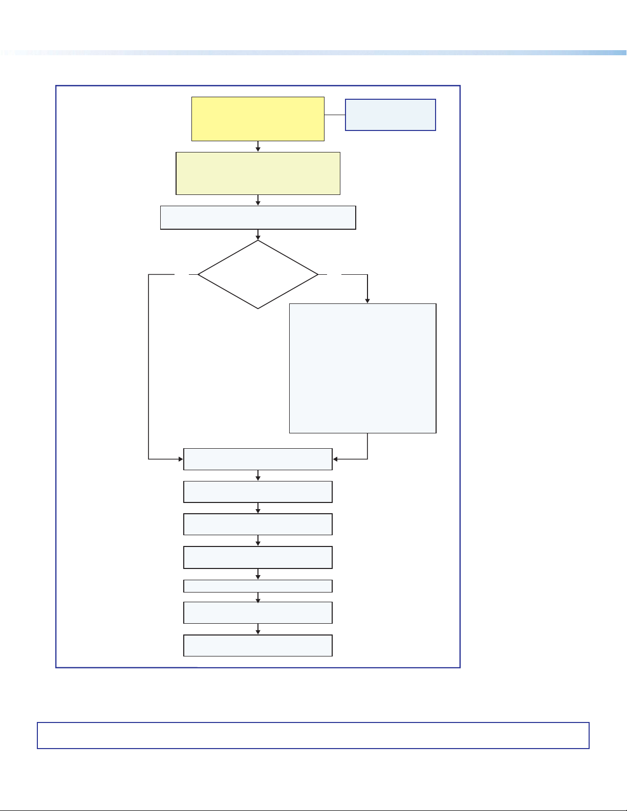
Overall Configuration Procedure for the Control Processor
Within Global Configurator
(GC Professional or
GC Plus mode):
Create a new GC Professional or GC Plus project
No Yes
Configure the IP settings
of the control processor,
NBP network button panels, and
TouchLink Pro touchpanels.
If desired or required, use
Toolbelt or other software to congure
security settings for 802.1X, SSL.
Upload security certicates, private keys.
and add the control processor to it.
Will
TouchLink Pro or
third party touchpanels or
other user interfaces
be used?
Create GUI layouts for the
touchpanels or other interfaces:
1. Start GUI Designer.
2. Create GUI layout designs for each
TouchLink Pro, third party
touchpanel (with a TouchLink
Interface), or a computer or
mobile device (with LinkLicense).
3. Save and build the GUI layout le.
Or...
Download existing GUI layouts
from identical touchpanels.
Network
See Network
Communication Setup
Communication Setup
on page 3.
Congure ports on the
control processor.
Create monitors, schedules, timers,
macros, and local variables.
Add touchpanels, other interfaces, or
button panels (if used) to the project.
Import GUI layouts and congure the
touchpanels or other interfaces.
Save the project.
Build and upload the conguration to
the control processor.
Test the system, make adjustments,
nalize conguration.
Figure 4. Overall Configuration Steps
For information on safety guidelines, regulatory compliances, EMI/EMF compatibility, accessibility, and related topics, see the
Extron Safety and Regulatory Compliance Guide on the Extron website.
10
© 2021 - Extron All rights reserved. www.extron.com
All trademarks mentioned are the property of their respective owners.
Worldwide Headquarters: Extron USA West, 1025 E. Ball Road, Anaheim, CA 92805, 800.633.9876
68-3496-52
Rev. A
02 21
 Loading...