

Page 1

IPCP 505
IP Link Control Processor
User Guide
IP Link® Products
68-2026-01 Rev. C
03 20
Page 2
Safety Instructions
Safety Instructions • English
WARNING: This symbol, ,when used on the product, is
intended to alert the user of the presence of uninsulated dangerous
voltage within the product’s enclosure that may present a risk of electric
shock.
ATTENTION: This symbol, , when used on the product, is intended
to alert the user of important operating and maintenance (servicing)
instructions in the literature provided with the equipment.
For information on safety guidelines, regulatory compliances, EMI/EMF
compatibility, accessibility, and related topics, see the Extron Safety and
Regulatory Compliance Guide, part number 68-290-01, on the Extron
website, www.extron.com.
Sicherheitsanweisungen • Deutsch
WARNUNG: Dieses Symbol auf dem Produkt soll den Benutzer
darauf aufmerksam machen, dass im Inneren des Gehäuses dieses
Produktes gefährliche Spannungen herrschen, die nicht isoliert sind und
die einen elektrischen Schlag verursachen können.
VORSICHT: Dieses Symbol auf dem Produkt soll dem Benutzer in
der im Lieferumfang enthaltenen Dokumentation besonders wichtige
Hinweise zur Bedienung und Wartung (Instandhaltung) geben.
Weitere Informationen über die Sicherheitsrichtlinien, Produkthandhabung,
EMI/EMF-Kompatibilität, Zugänglichkeit und verwandte Themen finden Sie in
den Extron-Richtlinien für Sicherheit und Handhabung (Artikelnummer
68-290-01) auf der Extron-Website, www.extron.com.
Instrucciones de seguridad • Español
ADVERTENCIA: Este símbolo, , cuando se utiliza en el producto,
avisa al usuario de la presencia de voltaje peligroso sin aislar dentro del
producto, lo que puede representar un riesgo de descarga eléctrica.
ATENCIÓN: Este símbolo, , cuando se utiliza en el producto, avisa
al usuario de la presencia de importantes instrucciones de uso y
mantenimiento recogidas en la documentación proporcionada con el
equipo.
Para obtener información sobre directrices de seguridad, cumplimiento
de normativas, compatibilidad electromagnética, accesibilidad y temas
relacionados, consulte la Guía de cumplimiento de normativas y seguridad
de Extron, referencia 68-290-01, en el sitio Web de Extron, www.extron.com.
Instructions de sécurité • Français
AVERTISSEMENT : Ce pictogramme, , lorsqu’il est utilisé sur le
produit, signale à l’utilisateur la présence à l’intérieur du boîtier du
produit d’une tension électrique dangereuse susceptible de provoquer
un choc électrique.
Istruzioni di sicurezza • Italiano
AVVERTENZA: Il simbolo, , se usato sul prodotto, serve ad
avvertire l’utente della presenza di tensione non isolata pericolosa
all’interno del contenitore del prodotto che può costituire un rischio di
scosse elettriche.
ATTENTZIONE: Il simbolo, , se usato sul prodotto, serve ad
avvertire l’utente della presenza di importanti istruzioni di funzionamento
e manutenzione nella documentazione fornita con l’apparecchio.
Per informazioni su parametri di sicurezza, conformità alle normative,
compatibilità EMI/EMF, accessibilità e argomenti simili, fare riferimento
alla Guida alla conformità normativa e di sicurezza di Extron, cod. articolo
68-290-01, sul sito web di Extron, www.extron.com.
Instrukcje bezpieczeństwa • Polska
OSTRZEŻENIE: Ten symbol, , gdy używany na produkt, ma na celu
poinformować użytkownika o obecności izolowanego i niebezpiecznego
napięcia wewnątrz obudowy produktu, który może stanowić zagrożenie
porażenia prądem elektrycznym.
UWAGI: Ten symbol, , gdy używany na produkt, jest przeznaczony do
ostrzegania użytkownika ważne operacyjne oraz instrukcje konserwacji
(obsługi) w literaturze, wyposażone w sprzęt.
Informacji na temat wytycznych w sprawie bezpieczeństwa, regulacji
wzajemnej zgodności, zgodność EMI/EMF, dostępności i Tematy pokrewne,
zobacz Extron bezpieczeństwa i regulacyjnego zgodności przewodnik, część
numer 68-290-01, na stronie internetowej Extron, www.extron.com.
Инструкция по технике безопасности • Русский
ПРЕДУПРЕЖДЕНИЕ: Данный символ, , если указан
на продукте, предупреждает пользователя о наличии
неизолированного опасного напряжения внутри корпуса
продукта, которое может привести к поражению электрическим
током.
ВНИМАНИЕ: Данный символ, , если указан на продукте,
предупреждает пользователя о наличии важных инструкций
по эксплуатации и обслуживанию в руководстве,
прилагаемом к данному оборудованию.
Для получения информации о правилах техники безопасности,
соблюдении нормативных требований, электромагнитной
совместимости (ЭМП/ЭДС), возможности доступа и других
вопросах см. руководство по безопасности и соблюдению
нормативных требований Extron на сайте Extron: ,
www.extron.com, номер по каталогу - 68-290-01.
安全说明 • 简体中文
警告: 产品上的这个标志意在警告用户该产品机壳内有暴露的危险 电压,
有触电危险。
ATTENTION : Ce pictogramme, , lorsqu’il est utilisé sur le produit,
signale à l’utilisateur des instructions d’utilisation ou de maintenance
importantes qui se trouvent dans la documentation fournie avec le
matériel.
Pour en savoir plus sur les règles de sécurité, la conformité à la
réglementation, la compatibilité EMI/EMF, l’accessibilité, et autres sujets
connexes, lisez les informations de sécurité et de conformité Extron, réf.
68-290-01, sur le site Extron, www.extron.com.
注意: 产品上的这个标志意在提示用户设备随附的用户手册中有
重要的操作和维护(维修)说明。
关于我们产品的安全指南、遵循的规范、EMI/EMF 的兼容性、无障碍
使用的特性等相关内容,敬请访问 Extron 网站 , www.extron.com,参见
Extron 安全规范指南,产品编号 68-290-01。
Page 3
安全記事 • 繁體中文
警告: 若產品上使用此符號,是為了提醒 使用者,產品機殼內存在著
可能會導致觸電之風險的未絕緣危險電壓。
注意 若產品上使用此符號,是為了提醒使用者,設備隨附的用戶手冊中有
重 要 的 操 作 和 維 護( 維 修 )説 明 。
有關安全性指導方針、法規遵守、EMI/EMF 相容性、存取範圍和相關主題的詳細資
訊,請瀏覽 Extron 網站:www.extron.com,然後參閱《Extron 安全性與法規
遵守手冊》,準則編號 68-290-01。
安全上のご注意 • 日本語
警告: この記 号 が製品上に表示されている場合は、筐体内に絶縁されて
いない高電圧が流れ、感電の危険があることを示しています。
注意:この記号 が製品上に表示されている場合は、本機の取扱説明書に
記載されている重要な操作と保守( 整備)の 指示についてユーザーの注 意
を喚起するものです。
安全上のご注意、法規厳守、EMI/EMF適合性、その他の関連項目に
つ い て は 、エ クスト ロ ン の ウェ ブ サ イト www.extron.com よ り 『 Extron Safety
and Regulatory Compliance Guide』 ( P/N 68-290-01) をご覧ください。
안전 지침 • 한국어
경고: 이 기호 가 제품에 사용될 경우, 제품의 인클로저 내에 있는
접지되지 않은 위험한 전류로 인해 사용자가 감전될 위험이 있음을
경고합니다.
주의: 이 기호 가 제품에 사용될 경우, 장비와 함께 제공된 책자에 나와
있는 주요 운영 및 유지보수(정비) 지침을 경고합니다.
안전 가이드라인, 규제 준수, EMI/EMF 호환성, 접근성, 그리고 관련 항목에
대한 자세한 내용은 Extron 웹 사이트(www.extron.com)의 Extron 안전 및
규제 준수 안내서, 68-290-01 조항을 참조하십시오.
Copyright
© 2011-2020 Extron Electronics. All rights reserved. www.extron.com
Trademarks
All trademarks mentioned in this guide are the properties of their respective owners.
The following registered trademarks
(®)
, registered service marks
(SM)
, and trademarks
(™)
are the property of RGB Systems, Inc. or
Extron Electronics (see the current list of trademarks on the Terms of Use page at www.extron.com):
Registered Trademarks
(®)
Extron, Cable Cubby, ControlScript, CrossPoint, DTP, eBUS, EDID Manager, EDID Minder, Flat Field, FlexOS, Glitch Free, GlobalConfigurator,
GlobalScripter, GlobalViewer, Hideaway, HyperLane, IPIntercom, IPLink, KeyMinder, LinkLicense, LockIt, MediaLink, MediaPort, NetPA,
PlenumVault, PoleVault, PowerCage, PURE3, Quantum, ShareLink, Show Me, SoundField, SpeedMount, SpeedSwitch, StudioStation,
SystemIntegrator, TeamWork, TouchLink, V-Lock, VideoLounge, VN-Matrix, VoiceLift, WallVault, WindoWall, XPA, XTP, XTPSystems, and
ZipClip
Registered Service Mark
(SM)
: S3 Service Support Solutions
Trademarks
(™)
AAP, AFL (Accu-RATE Frame Lock), ADSP (Advanced Digital Sync Processing), Auto-Image, AVEdge, CableCover, CDRS (ClassD
Ripple Suppression), Codec Connect, DDSP (Digital Display Sync Processing), DMI (Dynamic Motion Interpolation), DriverConfigurator,
DSPConfigurator, DSVP (Digital Sync Validation Processing), eLink, EQIP, Everlast, FastBite, Flex55, FOX, FOXBOX, IPIntercom HelpDesk,
MAAP, MicroDigital, Opti-Torque, PendantConnect, ProDSP, QS-FPC (QuickSwitch Front Panel Controller), Room Agent, Scope-Trigger, SIS,
SimpleInstructionSet, Skew-Free, SpeedNav, Triple-Action Switching, True4K, True8K, Vector™ 4K, WebShare, XTRA, and ZipCaddy
Page 4

FCC Class A Notice
This equipment has been tested and found to comply with the limits for a Class A digital
device, pursuant to part15 of the FCC rules. The ClassA limits provide reasonable
protection against harmful interference when the equipment is operated in a commercial
environment. This equipment generates, uses, and can radiate radio frequency energy and,
if not installed and used in accordance with the instruction manual, may cause harmful
interference to radio communications. Operation of this equipment in a residential area is
likely to cause interference. This interference must be corrected at the expense of the user.
NOTE: For more information on safety guidelines, regulatory compliances,
EMI/EMF compatibility, accessibility, and related topics, see the “Extron Safety and
Regulatory Compliance Guide” on the Extron website.
Battery Notice
This product contains a battery. Do not open the unit to replace the battery. If the battery
needs replacing, return the entire unit to Extron (for the correct address, see the Extron
Warranty section on the last page of this guide).
CAUTION: Risk of explosion. Do not replace the battery with an incorrect type. Dispose
of used batteries according to the instructions.
ATTENTION : Risque d’explosion. Ne pas remplacer la pile par le mauvais type de pile.
Débarrassez-vous des piles usagées selon le mode d’emploi.
Page 5

Conventions Used in this Guide
Notifications
The following notifications are used in this guide:
ATTENTION:
• Risk of property damage.
• Risque de dommages matériels.
NOTE: A note draws attention to important information.
TIP: A tip provides a suggestion to make working with the application easier.
Software Commands
Commands are written in the fonts shown here:
^AR Merge Scene,,Op1 scene 1,1 ^B 51 ^W^C
[01] R 0004 00300 00400 00800 00600 [02] 35 [17] [03]
E X! *X1&* X2)* X2#* X2! CE}
NOTE: For commands and examples of computer or device responses mentioned
in this guide, the character “0” is used for the number zero and “O” is the capital
letter “o.”
Computer responses and directory paths that do not have variables are written in the font
shown here:
Reply from 208.132.180.48: bytes=32 times=2ms TTL=32
C:\Program Files\Extron
Variables are written in slanted form as shown here:
ping xxx.xxx.xxx.xxx —t
SOH R Data STX Command ETB ETX
Selectable items, such as menu names, menu options, buttons, tabs, and field names are
written in the font shown here:
From the File menu, select New.
Click the OK button.
Specifications Availability
Product specifications are available on the Extron website, www.extron.com.
Extron Glossary of Terms
A glossary of terms is available at http://www.extron.com/technology/glossary.aspx.
Page 6

Page 7

Contents
Introduction ...................................................1
Before You Begin ................................................ 1
What This Guide Covers ................................. 1
Conventions Used in This Guide ..................... 1
Important Information You Need Before
Installation ..................................................... 1
About the IPCP505 ........................................... 2
Features ......................................................... 2
Controlling Other Devices ............................... 3
Application Diagrams .......................................... 4
IR and RS-232 Device Control ............................ 5
How the IPCP505 Works: Components and
Interactions ........................................................ 6
Creating a Control System Using the IPCP with
Optional Extron TouchLink Touchpanels............. 6
System Requirements ........................................ 7
Hardware Requirements ................................. 7
Software Requirements .................................. 7
Hardware Features and Installation ...........8
Setup Checklist: How to Proceed
With Installation ................................................. 8
Prepare ........................................................... 8
Perform Physical Installation ........................... 8
Configure the IPCP ......................................... 8
Front Panel Features ......................................... 10
IR Learning Sensor ....................................... 10
Reset Features ............................................. 10
Mounting the IPCP505 .................................... 11
UL Rack Mounting Guidelines ....................... 11
Rear Panel Features and Connections .............. 12
Power Connections ...................................... 12
Bidirectional Control and Communication
Connections and Features ........................... 13
Unidirectional Control and Communication
Connections ................................................ 15
Additional Control Ports ................................ 17
Resetting the Unit ............................................. 18
Software-based
Configuration and Control .........................20
Configuration and Control: an Overview ............ 20
Basic Setup Steps: a Guide to this Section
and Other Resources ...................................... 21
Communicating with the IPCP .......................... 21
Configuring the IPCP for
Network Communication ................................. 21
Configuring the IPCP for Network Use
Via Global Configurator ................................ 22
Configuring the IPCP for Network Use
Via the ARP Command ................................ 22
Configuring the IPCP for Network Use
Via a Browser .............................................. 24
Configuring the IPCP for Network Use
Via SISCommands and Telnet ..................... 25
Setting up the PC for IP Communication
With an IPCP505 ........................................ 25
Global Configurator Software for Windows® ..... 29
Downloading the Software and
Getting Started ............................................ 29
PC System Requirements ............................. 29
Using Global Configurator: Helpful Tips......... 30
Advanced Configuration ................................... 31
IR Learning to Create Customized
IR Driver Files ............................................... 31
Printing a Wiring Block Diagram or a
GUI Configuration Report ............................ 32
Updating Firmware ....................................... 32
Advanced Serial Port Control ........................ 33
Saving and Uploading the Configuration ....... 38
Controlling an IPCP505 ................................... 38
Embedded Web Pages ................................. 38
GlobalViewer Web Pages ............................. 47
Controlling the IPCP505 with a Touchpanel ..... 50
Customizing the IPCP Control Web Pages ....... 51
Troubleshooting ................................................ 52
Power Connections ...................................... 52
Data Connections ......................................... 52
Device Control Connections and
Configuration ............................................... 52
IPCP 505 • Contents vii
Page 8

SIS Programming and Control ................... 53
Host-to-IPCP Communications ........................ 53
IPCP505-initiated Messages ........................ 53
Password Information ................................... 54
Error Responses ........................................... 54
Error Response References .......................... 54
Commands and Responses ............................. 54
Using the Command/Response Tables ......... 54
Entering SIS Commands: Helpful Tips .......... 55
Symbol Definitions ........................................ 56
Command/Response Table for
SIS Commands ........................................... 61
Reference Information ...............................79
Glossary ........................................................... 79
File Types: a Key to Extron-specific
File Names ...................................................... 80
Firmware Updates .......................................81
Determining the Firmware Version ..................... 81
Using the Global Configurator Software ........ 81
Using a Web Browser ................................... 81
Updating the Main Firmware ............................. 84
Locating and Downloading the Firmware ...... 84
Updating Firmware via Extron IP Link File
Manager Software ....................................... 85
Updating Firmware via
the IPCP Embedded Web Page ................... 86
Updating Firmware via
Extron Firmware Loader Software ................ 88
IPCP 505 • Contents viii
Page 9

Introduction
This section covers the following basic information you should know about this guide and
the product before installation:
• Before You Begin
• About the IPCP505
• Application Diagram
• IR and RS-232 Device Control
• How the IPCP505 Works: Components and Interactions
• Creating a Control System Using the IPCP with Optional Extron TouchLink
Touchpanels
• System Requirements
Before You Begin
What This Guide Covers
This user guide provides instructions for an experienced person to install and set up an
Extron IPCP505 IPLink Control Processor. This guide provides detailed information and
recommends best practices for cabling the control processor. It provides a brief overview of
the configuration process, and reference information.
Configure the control processor using Extron Global Configurator software. This guide does
not contain instructions on detailed software-related setup steps or details of configuration
within the software: those are covered in the Global Configurator Help File and help files for
related programs. The software help files describe how to use each program to download
drivers, add AV devices to a configuration, configure basic functions, and set up schedules,
e-mail alerts, touchpanel button configurations, and the like.
Conventions Used in This Guide
• Throughout this guide the IPCP505 is also referred to as the “IPCP,” “control
processor,” or “controller.”
• Global Configurator software is referred to as “GC”.
• The GlobalViewer application is sometimes referred to as “GV.”
• GlobalViewer Enterprise is referred to as “GVE.”
• Unless otherwise noted, in images of software or web pages, circled numbers
correspond to the like-numbered procedural steps.
Important Information You Need Before Installation
The order and types of setup tasks for the IPCP505 control processor and TouchLink
touchpanels are important. Pay close attention to them. Follow the setup checklist in the
Hardware Features and Installation on page8.
IPCP 505 • Introduction 1
Page 10
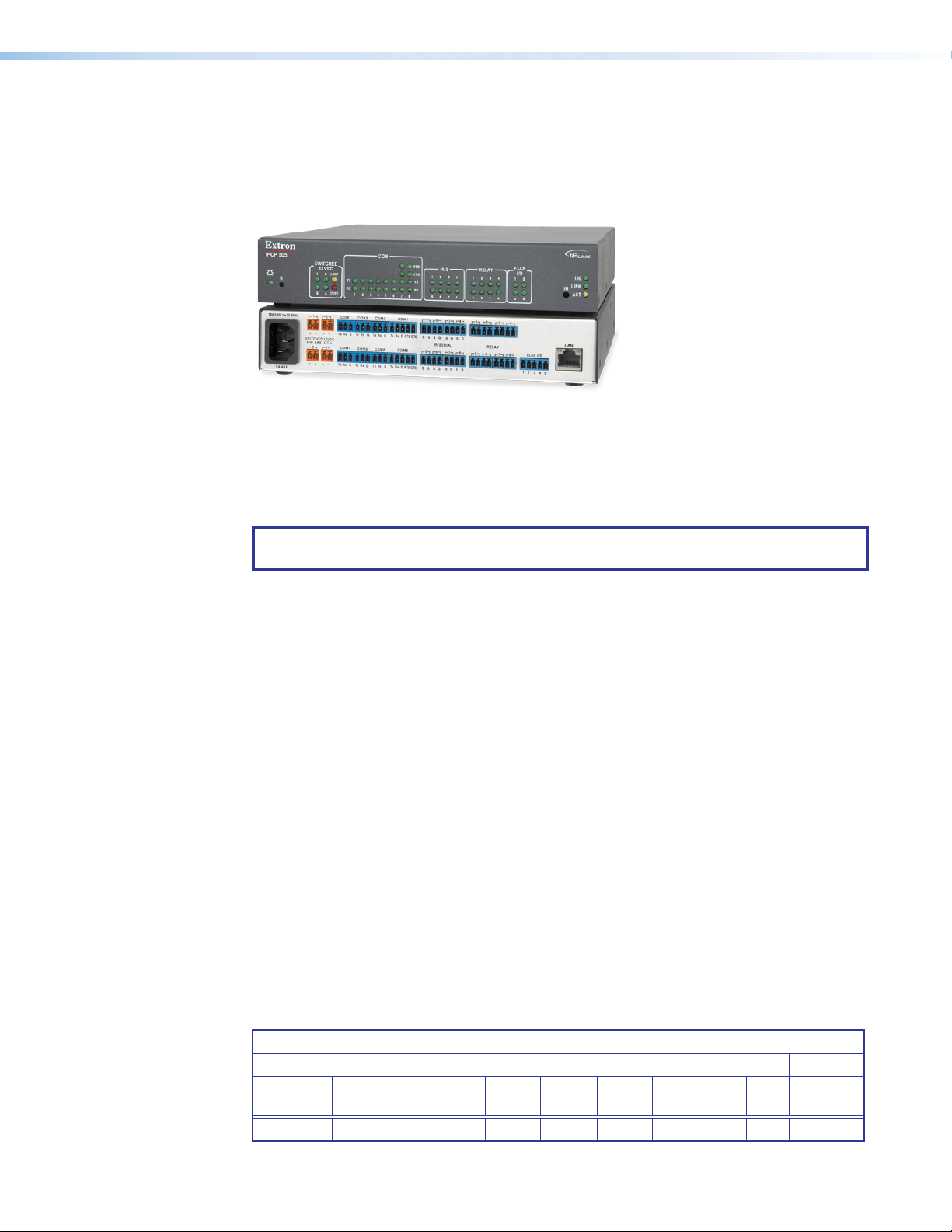
About the IPCP505
The IPCP505 can control and monitor a projector or other display device, source devices,
switchers, and various other items such as lights, a projector lift, or a screen motor. It can
used in a distributed control system environment or as a stand-alone controller. It allows
legacy products to be linked to and controlled via a network. The IPCP also can power
devices that accept 12VDC.
Figure 1. IPCP505
An IPCP505 control processor is the centerpiece of a control system that features Extron
TouchLink Touchpanels. The IPCP supports multiple TouchLink touchpanels over a standard
Ethernet network. The touchpanels provide a convenient interface for controlling the IPCP,
which, in turn, controls the other system components. Another option is to use a third-party
device such as a touchpanel or tablet in conjunction with Extron LinkLicense.
NOTE: GUI Configurator software is used to design the user interface layout of any
Extron TouchLink touchpanel or third-party touch interface that is used with the IPCP.
Features
Configure the control processor using GC. Once you have set up how you want it to work
(set up IP addresses and functions, assigned drivers to ports, configured relays and digital
input or output), that information is saved to a project configuration file that is built and
uploaded into the IPCP and to any optional TouchLink touchpanels.
General features
Flexible options for device control — The IPCP offers RS-232 and infrared (IR) control,
relays, and flex I/O (analog input or digital input or digital output) controls.
• The IPCP505 control processor with an IR receiver port can learn IR signals from remote
controls to communicate with sources such as DVD players. Users can create their own
IR device drivers or go to the Extron website (www.extron.com) to obtain drivers.
• It offers independently switched 12VDC power output.
Several mounting options — The standard 1U high enclosure is easily rack mounted or it
can be installed in or under furniture with an optional mounting kit.
Universal power system compatibility — The IPCP505 includes an internal power
supply that accepts 100-240 VAC, 50-60 Hz input.
Feature summary table
The following table provides a summary of major features.
Features
Ports
Power
Mounting
Rack Internal 4 6 2 8 8 4 1
Supply
Switched
12VDC Out
3-pole
COM
5-pole
COM
IR/
Serial Relay
Flex
I/O LAN
IR
Learning
IPCP 505 • Introduction 2
Page 11

Network and configuration features
The IPCP505 can be configured and controlled using a host computer via IP Link Ethernet
control. Setup and control can be accomplished by simple ASCII commands (Simple
Instruction Set, SIS) or via the free Global Configurator (GC) program. The GC software
offers many more setup options than does SIS programming. After being configured, the
IPCP can be controlled by a TouchLink touchpanel connected to the same network.
The IPCP505 integrates seamlessly with Extron GlobalViewer Enterprise (GVE) software and
the free GlobalViewer web-based AV resource management and remote control application.
The IPCP supports multiple TouchLink touchpanels over a standard Ethernet network. Global
Configurator and other useful software applications are available at www.extron.com.
Via Ethernet/IP communication you can access the embedded web pages of the IPCP505,
which include online diagnostics and monitoring of basic control features. As an integrated
part of the IPCP505, IP Link provides the following advantages:
• Global compatibility — The IPCP uses standard Ethernet communication protocols,
including ARP, DHCP, ICMP (ping), TCP, IP, Telnet, HTTP, and SMTP.
• Embedded web page serving — The IPCP505 offers up to 975 MB of flash
memory for storing Extron GlobalViewer and user-supplied web pages, configuration
settings, and device drivers. Data in flash memory is served at a transfer rate of 6 Mbps
(megabits per second).
• Remote equipment management — The IP Link connection allows you to remotely
manage, monitor, and control up to eight Ethernet-enabled products such as projectors,
cameras, video conferencing equipment, switchers, and other AV equipment. The IPCP
provides support for the following:
• TCP connections only
• Password-protected TCP connections
• Up to eight Ethernet drivers at a time
• Connection via IP address or host name
• A range of Telnet ports, when supported by the target device
• Multi-user support — Up to 200 simultaneous connections enable each IPLink
device to support many concurrent users and improve system throughput by sending
information in parallel.
• Built-in multilevel security — The user controls access to the devices attached
to the controller. Two levels of password protection (administrator and user) provide
appropriate security.
• Management ability via Global Configurator — The included software and the
GlobalViewer web pages associated with it allow you to control, monitor, and schedule
various functions of devices connected to IPLink products such as the IPCP.
• E-mail notification — The IPCP can be set up to send e-mail notifications, such as a
notice that a projector has been disconnected or the projector lamp has been used for
a designated number of hours.
Controlling Other Devices
The IPCP505 offers RS-232, infrared (IR), TCP/Ethernet control and monitoring, relay
device control, and control via flexible input/output (flex I/O) ports. It can learn IR signals
from remote controls to communicate with sources such as VCRs, DVD players, or
Blu-ray™ players. Users can create their own device drivers (IR) or go to the Extron website
(www.extron.com) to obtain device drivers.
The IPCP also provides four independently switched 12 VDC outputs, and can control up to
eight Ethernet-enabled AV devices.
IPCP 505 • Introduction 3
Page 12
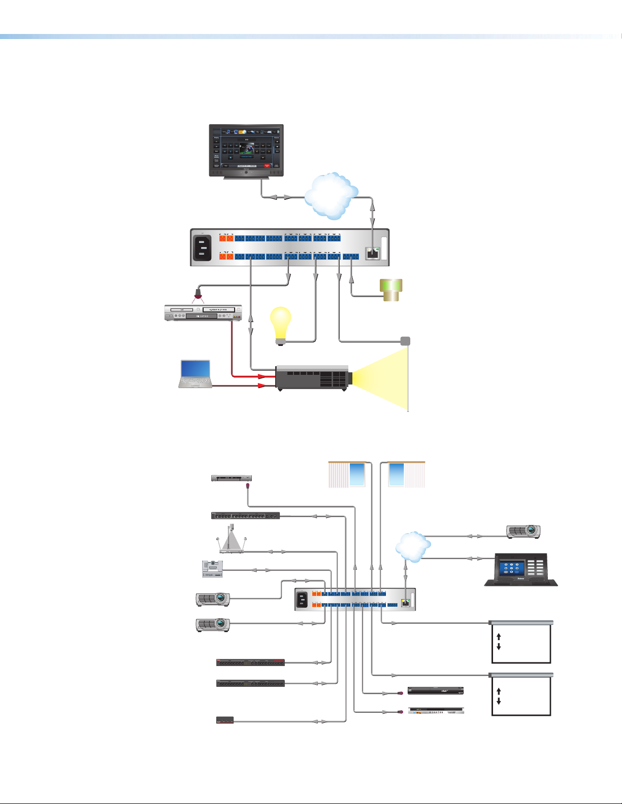
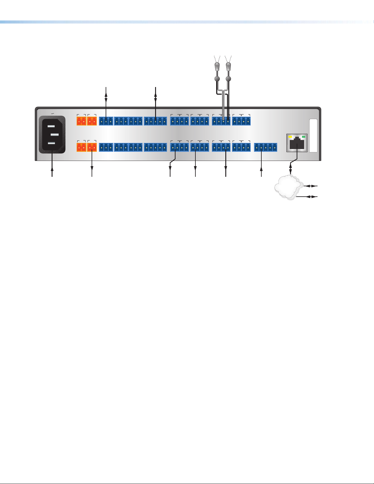
Application Diagrams
Sensor
Ext
MP
Medi
Matrix
Controller
The following figures show examples of types of devices that can be connected to some of
the ports on the IPCP505.
Extron
IPCP 505
IP Link Control Processor
100-240V 50-60Hz
5A MAX
Extron
IR Emitter
1 2
+-+
SWITCHED 12VDC
40W MAX TOTAL
3 4
+-+
TX RX
-
TX RX
-
COM2
COM1
GGG
TX RX
COM4
COM5 COM6 COM8
GG
TX RX
COM3
TX RX
G
TX RX
Extron
TLP 1000TV
10" Tabletop
TouchLink
Touchpanel
Ethernet
COM7
SGSG
CTS
RTS
G
TX RX
SGSG
G
CTS
RTS
TX RX
IR
Lighting
System
TCP/IP
Network
Ethernet
1
2 3
4
1 2 3 4
SGSG
7
SGSG
8 5 6
RELAY
FLEX I/O
7 8
1 234G
IR/SERIAL
5
6
MAC: 00-05-A6-XX-XX-XX
S/N:
LAN
Digital I/O
Motion
DVD/VCR Combo
Relay
RS-232
Laptop
Projector
Figure 2. An Example Application
Audio Tuner
ron
X 423 A
a Presentation
Document
Camera
Camera 1
Projector 1
OUTPUTS/
AUDIO
1
1
2
MODESINGLESEPARATE
Extron
IR Emitter
Window Shades 1 Window Shades 2
IR
OUTPUTSINPUTS
MPX 423 A
S-VIDEO
MEDIA PRESENTATION MATRIX
2 3 4 I/O
MUTE
1
VOLUME
1
VIDEO
2
AUDIO
AUDIO OUTPUT 1
COMPUTER
VIDEO
INPUTS
OUTPUTSINPUTS
2 3 4
2 3 4
1
1
2
RS-232
RS-232
RS-232
RS-232
100-240V 50-60Hz
COM1
COM2
1 2
TXRX
GGG
TXRX
+-+
-
SWITCHED 12VDC
40W MAX TOTAL
COM5 COM6 COM8
COM4
3 4
GG
TXRX
TXRX
+-+
-
5A MAX
RS-232
Screen
Relay
Relay
COM3
COM7
1
2 3
SGSG
CTS
RTS
TXRX
G
TXRX
IR/SERIAL
6
5
SGSG
CTS
RTS
G
G
TXRX
TXRX
Control
Relay
TCP/IP
Network
Ethernet
Ethernet
4
1 2 3 4
SGSG
RELAY
7
8 5 6
7 8
SGSG
Extron
MAC: 00-05-A6-XX-XX-XX
S/N:
IPCP 505
LAN
FLEX I/O
IP Link
1234G
Control Processor
Relay
Projector 3
LAPTOP
DVD
PC
DVD
DOC CAM
Video
<<
More
AUXILIARY
TLP 350CV
DISPLAY ON
DISPLAY OFF
MUTE
VOLUME
VOLUME
Projector 2
Extron
IN1508
Switcher
Extron
IN1508
Switcher
Extron
MVC 121
Mixer/volume
IR
IR
VOL
MIC 1
MIC 2MAIN 3MASTER
INPUT OUTPUT RATE PIP
INPUT OUTPUT RATE PIP
MVC 121
MIXER/VOLUME CONTROLLER
SCALING PRESENTATION SWITCHER
PICTURE CONTROL
CONT/
COL/
ON7654321 SWAP8CENTER SIZE
MENU ENTER
BRT
TNT
VGA
1024x852
UXGA
SVGA
1024x1024
720p
XGA
1366x768
1080i
SXGA
1365x1024
1080p
SCALING PRESENTATION SWITCHER
PICTURE CONTROL
CONT/
COL/
ON7654321 SWAP8CENTER SIZE
MENU ENTER
BRT
TNT
VGA
1024x852
UXGA
SVGA
1024x1024
720p
XGA
1366x768
1080i
SXGA
1365x1024
1080p
RS-232
IN1508
RS-232
IN1508
RS-232
Figure 3. A Typical IPCP505 Application
IR
IR
Relay
Extron
IR Emitter
Screen Controller 1
DVD 1
TM
DVD 2
Screen Controller 2
IPCP 505 • Introduction 4
Page 13
IR Emitters
lights)
Device
Device
on TLP
Rear Panel
100-240V 50-60Hz
RS-232 Enabled
1 2
+-+
-
SWITCHED 12VDC
40W MAX TOTAL
3 4
AV Device
RS-232
COM1
TX RX
GGG
COM4
RS-232, RS-422, or
RS-485 Enabled
AV Device
COM2
COM3
TX RX
TX RX
COM5 COM6 COM8
COM7
TX RX
RS-232,
RS-422, or
RS-485
G
CTS
RTS
1
2 3
SGSG
IR/SERIAL
5
6
(to IR-controllable devices)
IR
4
1 2 3 4
SGSG
7
8
RELAY
5 6
7 8
FLEX I/O
LAN
MAC: 00-05-A6-XX-XX-XX
S/N:
5A MAX
100-240 VAC
Input
+-+
TX RX
-
Device that
Requires 12 VDC
GG
TX RX
TX RX
G
TX RX
G
Input
Figure 4. Signal Flow and Generic Connection Types
IR and RS-232 Device Control
The IPCP must be configured in one of the following ways before it will send commands to a
projector, display, or other device:
• An IR or an RS-232 driver file can be downloaded from the Extron website
(www.extron.com/download/index.aspx), or downloaded from the extensive Extron
driver library using the driver subscription feature within Global Configurator. The
driver is saved to a folder and commands from the driver are incorporated into the GC
configuration file for the control processor and any touchpanels that will work with it.
The configuration file is built and uploaded to the IPCP via Global Configurator.
• If a driver is not already available, RS-232 or Ethernet command strings can be
entered directly from a host computer using GlobalConfigurator. These can then be
incorporated into controls within the GC project.
• IR commands can be entered directly from an IR remote control through IR learning
via IRLearner software to create a driver that the unit can use. IR learning is seldom
needed, but it is convenient for adding new or updated commands in the field in the
rare cases when a driver is not already available from Extron.
See the Global Configurator Help File or the IR Learner Help File (which come with the
software) for details on setting up the IPCP and for downloading, programming, or learning
device control commands.
CTS
RTS
Hardwired
IR
Control
Port on
an AV
SGSG
IRPowerPower
SGSG
RS-232
Hardwired
Serial
Control
Port on
an AV
Room Control
Equipment
(screen
control,
projector lift,
1234G
Switch,
Sensor, or
Contact
Closure
Device
TCP/IP
Network
Ethernet
Extr
Touchpanel
PC
IPCP 505 • Introduction 5
Page 14
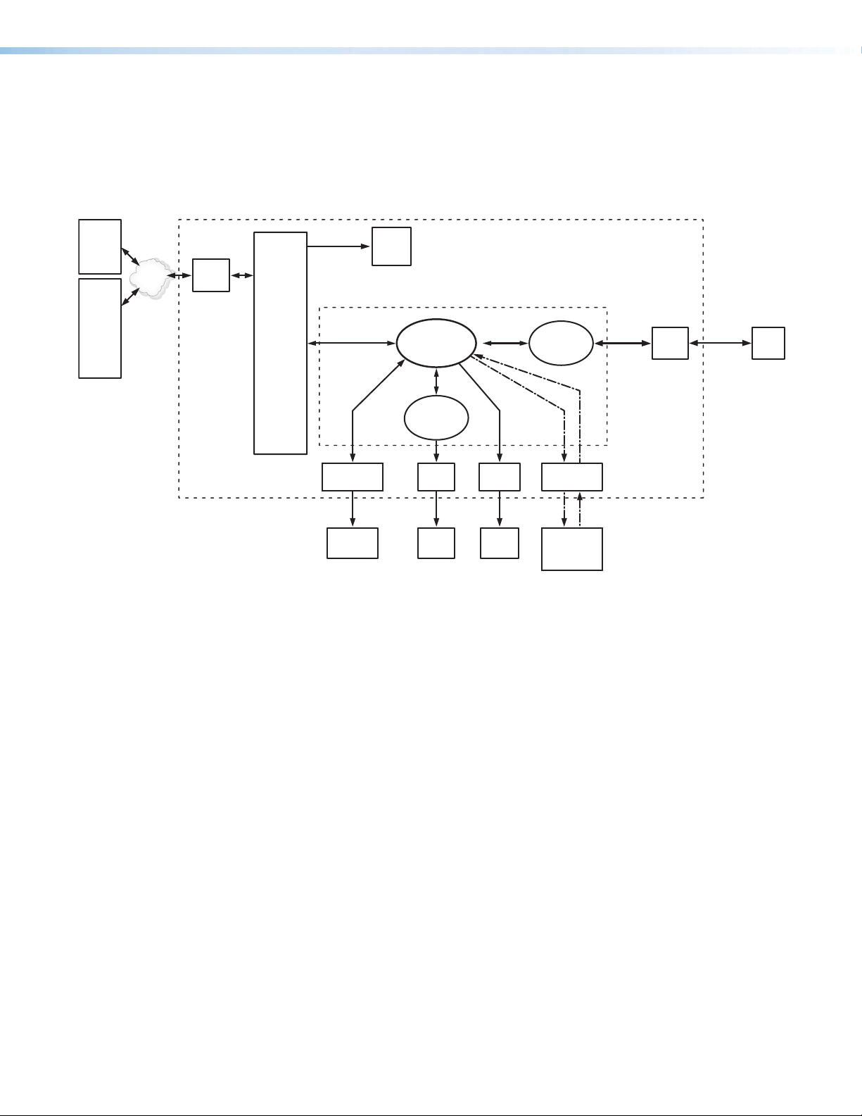
How the IPCP505 Works: Components and Interactions
The IPCP505 requires and uses event files to perform functions. The event files define,
monitor, and govern how an IPCP505 works. The following diagram is an example of how
the IPCP interacts with accessories, event scripts, drivers, ports, input devices, and output
devices.
IPCP 505
Touch-
™
Link
touch-
panel
PC
with
Global
Cong-
urator
or
Web
Browser
TCP/IP
Network
LAN
Port
IPCP 505
Firmware
Front
Panel
LEDs
MAIN EVENT
(___.evt)
DVD Driver
(___.evt)
Memory
Proj. Driver
(___.evt)
or
Serial
Driver
Com
Port
2-way
RS-232
Proj.
Power Output
Port
Powered
Device
IR
Port
IR12 VDC
DVD
Player
Relay
Port
Screen
Control
Flex I/O
Port
Sensor,
Switch, LED,
or Relay
Figure 5. How the IPCP 505 Works
The IPCP can be configured completely via Global Configurator software. Once you have
set up how you want it to work (assigned drivers to ports, configured relays and contact
closure input, and set up IP addresses and functions), that information is saved to a project
file that is uploaded into the IPCP.
The configuration information is used to create the “main event” (0.evt) script file that defines
the operation of the IPCP. The main event file also controls and monitors ports and optional
control accessories. Scripts are compiled to generate the main event file to monitor events
and to generate actions (such as issuing commands and triggering relays).
Creating a Control System Using the IPCP with Optional Extron TouchLink Touchpanels
Not only can the IPCP505 act as a stand-alone controller that can be accessed via its
internal and GlobalViewer web pages, but it also can act as the centerpiece of a control
system that features Extron TouchLink Touchpanels. The touchpanels provide a convenient,
aesthetically pleasing interface for controlling the IPCP, which, in turn, controls the other
system components.
If you have additional questions or require support for your Extron control system
installation, contact the Extron S3 Control Systems Support Hotline.
IPCP 505 • Introduction 6
Page 15

System Requirements
The IPCP505, Global Configurator, and GUI Configurator have the following minimum
hardware and software requirements:
Hardware Requirements
Processor Intel® Pentium® III, 1 GHz Intel Pentium 4 or AMD™ Athlon
RAM 512 MB 1 GB (2 GB is recommended for
Available hard disk space 50 MB 100 MB
Screen resolution 1024x768
A network connection with a minimum data transfer rate of 10 Mbps
(100 Mbps is recommended)
Software Requirements
Global Configurator GUI Configurator
™
multiple or large projects)
Global Configurator and
GUI Configurator
GlobalViewer
Operating system • Microsoft® Windows® XP,
service pack 2
• Windows Vista
®
or
• Windows 7
• Microsoft Windows XP,
service pack 3
• Windows Vista
or
• Windows 7
ATTENTION:
• Do not run Global Configurator software on a PC
that uses an earlier version of Windows.
• Ne faites pas fonctionner le logiciel
GlobalConfigurator sur un ordinateur qui utilise
une version plus récente de Windows.
Microsoft Windows Script version 5.6
Microsoft .NET framework version 4.0 or higher
Browser Microsoft Internet Explorer®
version 6.0 or higher
with ActiveX® enabled
NOTE: GUI Configurator is used to set up any Extron TouchLink touchpanel that will be
used with the IPCP.
IPCP 505 • Introduction 7
Page 16

Hardware Features and Installation
This section covers the following material:
• Setup Checklist: How to Proceed With Installation — A checklist of tasks to guide
you through installation
• Front Panel Features — Locations and some descriptions of items on the front panel
• Mounting the IPCP505 — Brief guidelines for mounting
• Rear Panel Features and Connections — Locations, descriptions, and cabling notes
for rear panel features and corresponding front panel indications
• Resetting the Unit — Information about the available reset modes and how to reset
the IPCP
Setup Checklist: How to Proceed With Installation
Prepare
Familiarize yourself with the features of the IPCP505.
Install the latest version of the Extron Global Configurator (GC) software (version 3.2 or
higher), the latest driver package, and any additional software such as GUI Configurator,
GlobalViewer Enterprise (GVE) or IR Learner (available from www.extron.com).
Obtain IP setting information from the network administrator for the IPCP.
Obtain model names and setup information for devices that the IPCP will control.
Perform Physical Installation
Mount the unit to a rack or projector mount (see the instructions on page11).
Connect the IPCP505 to a network (LAN) and connect other devices to the IPCP (see
Rear Panel Features and Connections starting on page12 or see the “Setup”
section of the IPCP505 Setup Guide).
Connect power cords and turn on the output devices (projectors, monitors, speak-
ers), the IPCP, a PC (for setup) or touchpanel (for control after configuration), and input
devices (DSS, cable boxes, and the like).
Configure the IPCP
Connect the PC and the IPCP505 to the same Ethernet network (see page14) and
use Telnet, Extron DataViewer, or a similar application to configure the IPCP for network
communication.
Connect any Extron TLP touchpanels that will be part of the system to the same network
as the PC and IPCP. Create a user interface layout for the touchpanels and upload the
GUI configuration to each touchpanel. See the GUI Configurator Help File for instructions.
IPCP 505 • Hardware Features and Installation 8
Page 17

Create a new GC project and configure the IPCP505. See the Global Configurator Help
File.
Set the IP address and subnet mask for the IPCP, and other IP settings.
Define the GlobalViewer Tree location of the unit.
Add the IPCP to the project.
Define e-mail settings and contacts.
Add serial, IR, and Ethernet device drivers.
Configure the ports on the IPCP and assign device drivers as needed.
Configure touchpanel buttons, if applicable, in Global Configurator.
Create a display shutdown schedule.
If a projector is part of the system and if desired, create a display lamp hours notifi-
cation e-mail.
Create a display disconnection notification e-mail.
Perform configurations for special applications, if needed.
Save the Global Configurator project/configuration.
Build and upload the configuration.
Test the system.
IPCP 505 • Hardware Features and Installation 9
Page 18
Front Panel Features
Power LE
Network
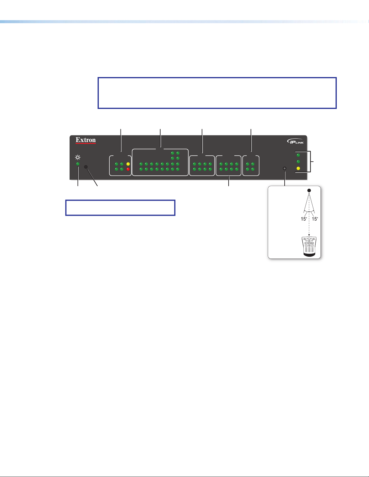
Front panel features are shown below. Most of the features and LED indications are
described and shown in Rear Panel Features and Connections on page12 paired
with the descriptions of the corresponding rear panel ports.
NOTE: The IPCP505 must be set up in order to function. See the Software-
based Configuration and Control section starting on page20 and the Global
Configurator Help File for information about Global Configurator, which you must use
to set up the unit.
Switched
12 VDC LEDs
IPCP 505
SWITCHED
12VDC
LIMIT
314
2
OVER
(recessed)
TX
RX
R
Reset Button
D
NOTE: Numbers adjacent to LEDs correspond
to the like-numbered rear panel ports.
Figure 6. IPCP505 Front Panel
IR Learning Sensor
COM (Serial) LEDs
COM
12345678
IR/Serial LEDs
RTS
IR/S
CTS
TX
RX
5162738
RELAY
4
516
Relay LEDs
Flex I/O LEDs
2
4
738
FLEX
314
I/O
2
100
LINK
IR
ACT
LAN/
LEDs
IR Receiver
IR Learning
Angle
and
Distance
2–12"
(4–30 cm)
1 2 3
4 5 6
7 809
In most cases, Extron has already produced a driver file for controlling the projector, display,
or source device you plan to use. If a device driver file is not available, you can create your
own using Extron IR Learner software, the remote control of the projector or display, and the
IR learning receiver sensor on the IPCP, shown the figure above.
This receiver accepts infrared signals of from 30 kHz to 1 MHz. The IR remote control must
be pointed directly at the receiver for best results. The front panel diagram indicates the best
distances and angles at which to hold the remote control.
Reset Features
Reset button and LED — Pressing this recessed button causes various IP functions
and Ethernet connection settings to be reset to the factory defaults. The green LED flashes
depending on the selected reset mode (see Resetting the Unit and the reset modes table
on page18 for details).
IPCP 505 • Hardware Features and Installation 10
Page 19
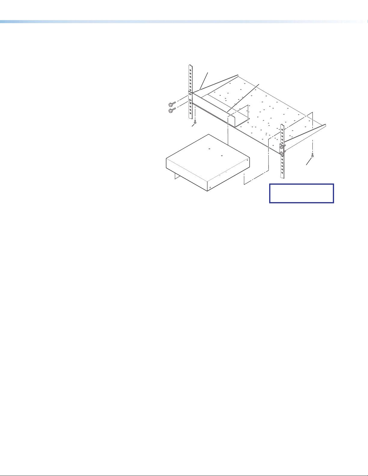
Mounting the IPCP505
Optional rack shelves are available for use with the IPCP.
Read the
instructions that
come with the rack
shelf or mounting kit
for installation
procedures.
The IPCP505
includes rubber feet
so it can be set on
a table. If you are
going to mount the
unit to a rack shelf
and these feet were
attached to the
enclosure, remove
the feet before
mounting.
UL Rack Mounting Guidelines
Front false
faceplate
uses 2
screws.
1U Universal Rack Shelf
Use 2 mounting
holes on opposite
corners.
1/2 Rack Width Front False
Faceplate
(2) 4-40 x 3/16"
Screws
NOTE: Using screws longer
than 3/16" will damage the
unit and void the warranty.
The following Underwriters Laboratories (UL) guidelines pertain to the safe installation of
the IPCP505 in a rack.
1. Elevated operating ambient temperature — If installed in a closed or multi-unit
rack assembly, the operating ambient temperature of the rack environment may be
greater than room ambient temperature. Therefore, install the IPCP in an environment
compatible with the maximum ambient temperature (Tma = +122 °F, +50 °C) specified
by Extron.
2. Reduced air flow — Install the equipment in a rack so that the amount of air flow
required for safe operation of the equipment is not compromised.
3. Mechanical loading — Mount the equipment in the rack so that a hazardous
condition is not achieved due to uneven mechanical loading.
4. Circuit overloading — Connect the equipment to the supply circuit and consider the
effect that circuit overloading might have on overcurrent protection and supply wiring.
Appropriate consideration of equipment nameplate ratings should be used when
addressing this concern.
5. Reliable earthing (grounding) — Maintain reliable grounding of rack-mounted
equipment. Pay particular attention to supply connections other than direct connections
to the branch circuit (such as use of power strips).
IPCP 505 • Hardware Features and Installation 11
Page 20
Rear Panel Features and Connections
Rear
MAC
IPCP 505
C
Lights if total power draw is
Panel
100-240V 50-60Hz
5A MAX
+-+
SWITCHED 12VDC
40W MAX TOTAL
+-+
1 2
3 4
COM1
TX RX
-
COM4
TX RX
-
COM2
COM3
GGG
TX RX
TX RX
COM5 COM6 COM8
GG
TX RX
TX RX
G
AAAAAAAA BBBBBBBB CCCCCCCC DDDDDDDD GGGGGGGG HHHHHHHH IIIIIIII EEEEEEEE
Power input
Power input
connector
connector
(see A
below)
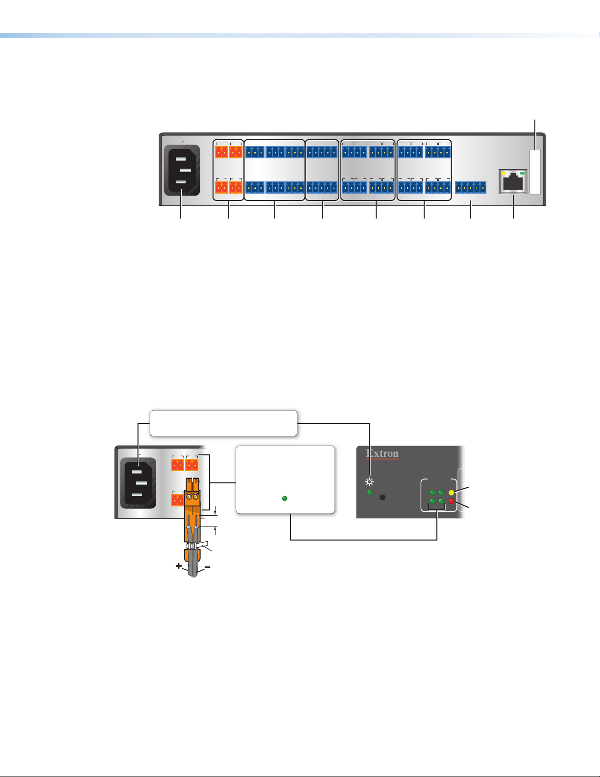
Figure 7. IPCP505 Rear Panel
Power Connections
Power input connector — Connect the IPCP to a 100-240 VAC power source here
A
(see figure 7, A, above, and figure 8 below).
Switched 12 VDC power output ports — These four ports provide 12VDC output
B
up to a combined maximum of 40 watts. Once configured, each port can be separately
turned on or off. These ports are monitored continuously for total power usage (draw).
Switched
Switched
12 VDC power
12VDC power
output ports
output ports
(see B below)
COM1 -
COM1 -
COM6
COM6
RS-232 ports
RS-232 ports
(page 13)
COM7, COM8
COM7, COM8
RS-485 ports
RS-485 ports
COM7
G
TX RX
RTS
G
RTS
TX RX
RS-232/
RS-232/
RS-422/
RS-422/
(page 15)
CTS
CTS
1
2 3
SGSG
IR/SERIAL
5
6
SGSG
SGSG
7
SGSG
IR/serial
IR/serial
output
output
ports
ports
(page 15)
4
1 2 3 4
5 6
8
RELAY
7 8
Relay
Relay
ports
ports
(page 16)
FLEX I/O
1234G
Flex I/O
Flex I/O
(digital input/
(digital input/
output or
output or
analog input)
analog input)
ports
ports
(page 17)
MAC
address
address
(page 14)
LAN
LAN
LAN
(Ethernet)
(Ethernet)
connector
connector
and LEDs
and LEDs
(page 14)
FFFFFFFF
MAC: 00-05-A6-XX-XX-XX
S/N:
100-240V 50-60Hz
5A MAX
Rear Panel
Power Input
• Connect to 100 to
240 VAC.
1 2
+-+
SWITCHED 12VDC
40W MAX TOTAL
3 4
+-+
• Front panel LED lights when
the IPCP receives power.
-
-
Tie Wrap
• 12 VDC, 40 watts (max.)
• Corresponding front panel
3/16"
(5 mm)
Max.
Switched 12 VDC
Power Output
= total output for all four ports
combined
green LEDs ( ) light when
power is available at each port.
R
Front Panel
SWITCHED
12VDC
2
314
LIMIT
40-44 watts.
OVER
Lights if total power draw
exceeds 44 watts.
Power output shuts off.
The user must turn these
ports back on.
Figure 8. AC Input and Switched Power Output Ports
• When the total power usage exceeds a threshold of 40watts but is still below
44watts, the IPCP enters the limit mode, during which the yellow front panel
LimitLED lights. If you have configured the unit to do so, the IPCP can issue a
power overcurrent notice.
• If power usage exceeds a second, higher threshold (44watts), the IPCP enters
overcurrent mode. It turns these ports off, and the red front panel Over LED lights.
If the ports are disabled, the user must disconnect or fix the attached devices to
correct the problem, after which power output can be re-enabled via controls in the
IPCP internal web pages or via an SIS command.
IPCP 505 • Hardware Features and Installation 12
Page 21
Bidirectional Control and Communication Connections and Features
5
100
0V 50-6
0H
S
2V
2VDC
AX T
TO
2
3
R
O
E
C
Rear
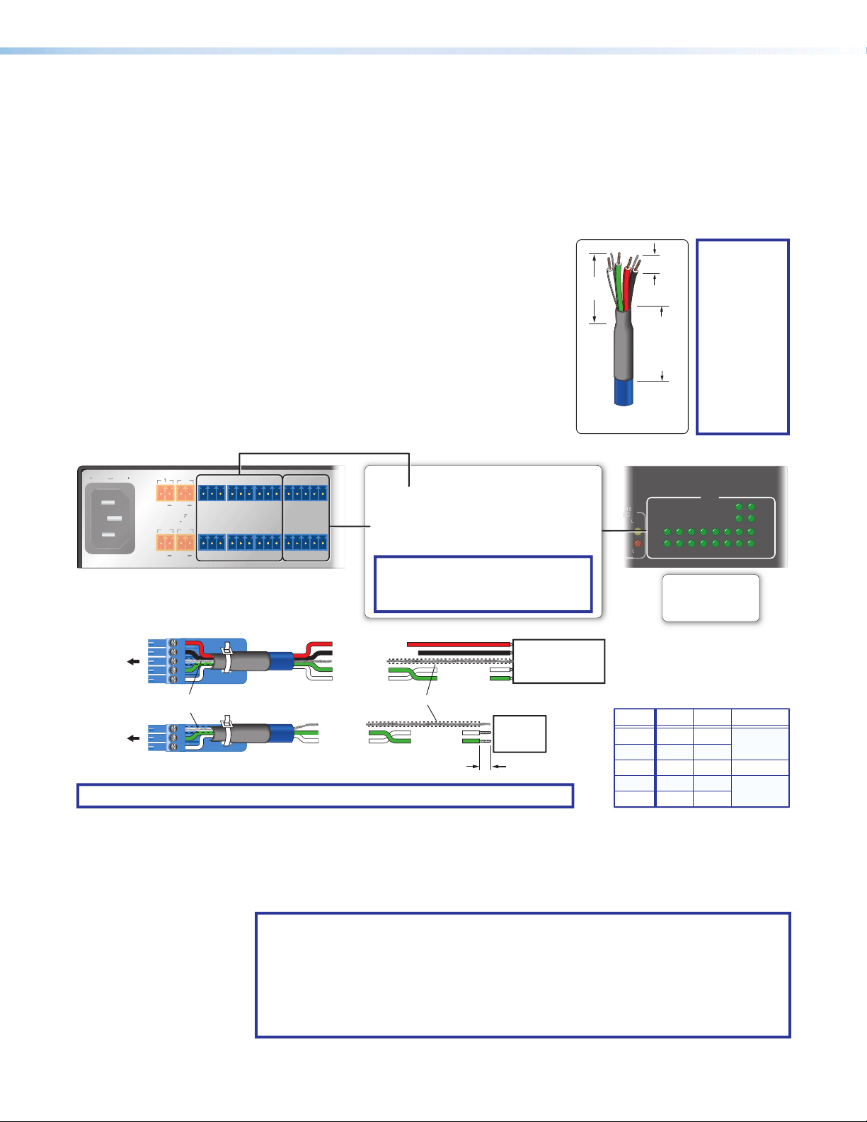
COM1 through COM6 RS-232 ports (-5 VDC to +5 VDC) (see figure 7 on
C
page12) and
COM7 and COM8 RS-232/RS-422/RS-485 ports (-5 VDC to +5 VDC) — Use
D
COM ports for serial control of a display or other device and to receive status messages
from the connected devices. These ports can send commands from a driver file.
IPCP505 serial protocol:
• 300 to 115200 baud (9600 baud = default)
Extron
3/16"
(5 mm)
Max.
Heat Shrink
on Outer
Jacket to
Inner
Conductor
Transition
TX
RX
VE
• 8 (default) or 7 data bits
• 1 (default) or 2 stop bits
• No parity (default), or even or odd parity
7/8"
(22 mm)
• Flow control support
• COM1 - COM6: software-only
(XON, XOFF)
• COM7 and COM8:
hardware and software
Use the following diagram as a wiring guide to
cable the IPCP to other devices.
Panel Front Panel
Serial (COM) Ports
Select protocol via software or
(RS-232)
SIS command.
COM 1-8 port default protocol:
• 9600 baud
• 8 data bits • 1 stop bit
• no parity • no ow control
hardware and software ow control.
The 3-pole COM ports support software
ow control.
A MAX
WITCHED 1
40W M
TX RX
TAL
TX RX
COM1
COM2
GGG
TX RX
COM4
COM5 COM6 COM8
GG
TX RX
COM3
TX RX
TX RX
COM7
COM1 - COM6
G
CTS
TX RX
RTS
COM7, COM8
(RS-232, RS-422, RS-485)
G
CTS
RTS
G
TX RX
NOTE: The 5-pole COM ports support both
STP 20-2P Cable
TIP:
STP 20-2P
cable, shown
at left, is
recommended
for these
connections.
For best
results,
insulate the
common or
drain wires
using heat
shrink.
COM
12345678
RTS =
Request to Send
CTS = Clear to Send
Tx = Transmitting Data
Rx = Receiving Data
RTS
CTS
TX
RX
To COM7,
COM8
To COM1
- COM6
Heat Shrink
Over Shield Wires
RTS
G Ground
Rx Receive
Tx
G
Ground
Rx
Receive
Tx
Transmit
Clear to send
Request to send
Transmit
Strip wires
3/16" (5 mm) max.
Heat Shrink
Receive (Rx)
Transmit (Tx)
Receive (Rx)
Transmit (Tx)
Projector, Panel
Display, PC, or Other
RS-232, RS-422, or
RS-485 Device
RS-232-
Controllable
Device
CTS
NOTE: If you use cable that has a drain wire, tie the drain wire to ground at both ends.
Figure 9. Wiring for Serial Control
For bidirectional serial communication, the transmit, ground, and receive pins must be
wired at both the IPCP505 and the other device. Each projector or other device may
require different wiring. For details, see the manual for that equipment or read the Extron
device driver communication sheet.
NOTE: Maximum distances between the IPCP and the device being controlled
may vary up to 200 feet (61 m). Factors such as cable gauge, baud rates,
environment, and output levels (from the IPCP and the device being controlled) all
affect transmission distance. Distances of about 50 feet (15 m) are typically not a
problem. In some cases the IPCP may be capable of transmitting and controlling
a given device via RS-232 up to 250 feet (76 m) away, but the RS-232 response
levels of that device may be too low for the IPCP to detect.
COM7, COM8 Pin Configurations
RS-232
Pin
1 (Tx)
2 (Rx)
3 (G)
4 (RTS)
5 (CTS)
Tx
Rx
Ground
RTS
CTS
RS-422
Ground
Tx-
Rx-
Tx+
Rx+
RS-485
Data-
(pins 1 & 2
tied together)
Ground
Data+
(pins 4 & 5
tied together)
IPCP 505 • Hardware Features and Installation 13
Page 22
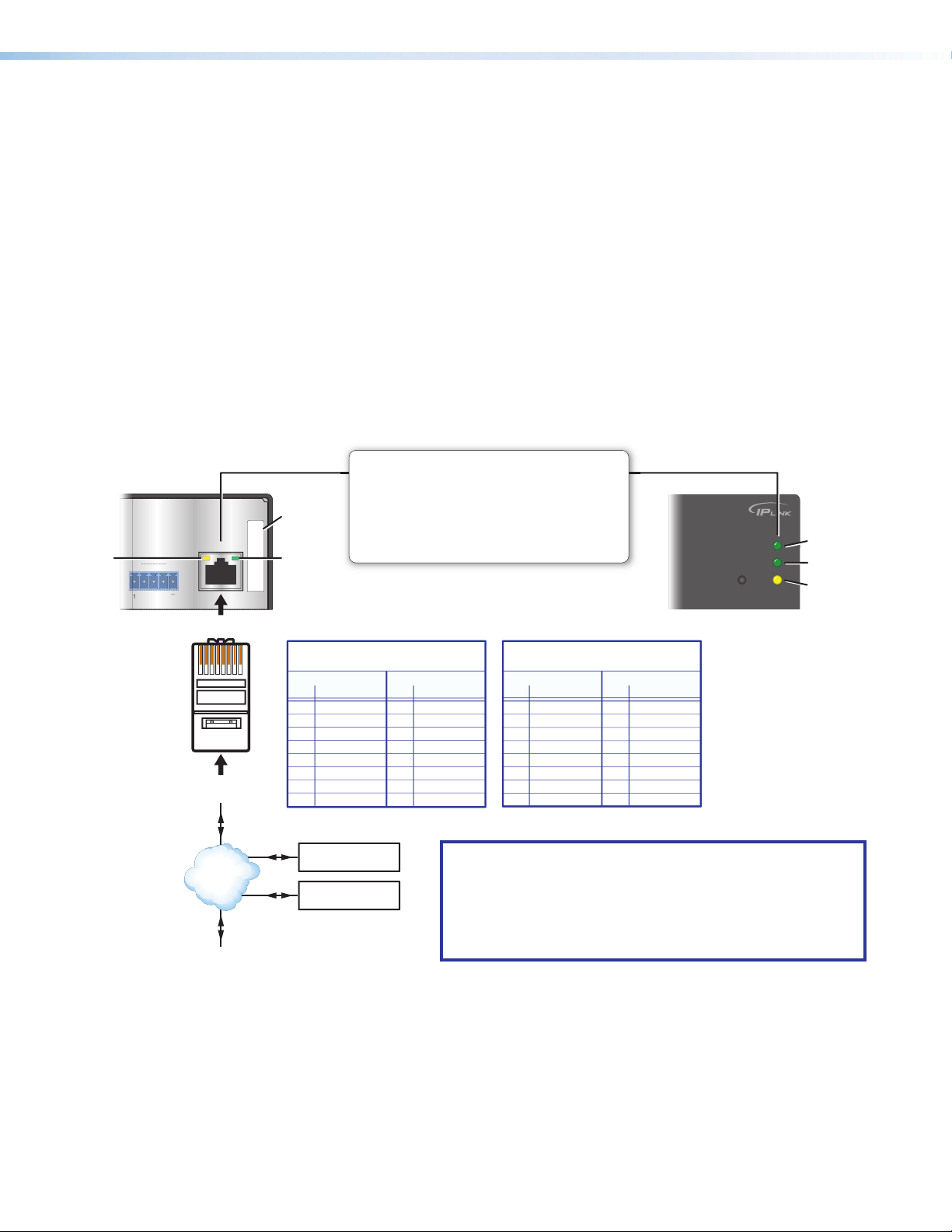
LAN (IP) connector and LEDs (see figure 7 on page12) — To connect the IPCP
234
A
LED
eceived.
PC
E
to an Ethernet network (so you can configure and control the IPCP and the devices
connected to it), plug a cable into this RJ-45 socket and connect the other end of the
cable to a network switch, hub, router, or PC connected to a LAN or the Internet.
Cabling:
• For 10Base-T (10 Mbps) networks, use a CAT 3 or better cable.
• For 100Base-T (max. 155 Mbps) networks, use a CAT 5 cable.
You must configure this port before using it. Configure the settings for this port via either
SIS commands or Global Configurator. See the programming sections (Software-
based Configuration and Control and SIS Programming and Control starting on
page53) of this guide for details on configuration.
Activity LED — This yellow LED blinks to indicate network activity.
Link LED — This green LED lights to indicate a good network connection.
100 LED (front panel) — This green LED lights when the unit is connected to a
100Mbps network connection.
Connect to an Ethernet network with a straight-through
Rear Panel Front Panel
MAC
Address
MAC: 00-05-A6-XX-XX-XX
S/N:
ctivity
EX I/O
RJ-45
Connector
Ethernet
LAN
Pins:
12345678
Insert Twisted
Pair Wires
TCP/IP
Network
Link
LED
(for connection to a switch, hub, or router)
End 1 End 2
Pin Wire Color Pin Wire Color
1 white-orange 1 white-orange
2 orange 2 orange
3 white-green 3 white-green
4 blue 4 blue
5 white-blue 5 white-blue
6 green 6 green
7 white-brown 7 white-brown
8 brown 8 brown
TLP Touchpanel
Extron Devices
(Switchers, Scalers)
cable. This port must be congured.
Default protocol:
• IPCP IP address: 192.168.254.254
• Gateway IP address: 0.0.0.0
• Subnet mask: 255.255.0.0
• DHCP: off
• Link speed and duplex level: autodetected
Straight-through Cable
Extron
LAN (Ethernet)
Crossover Cable
(for direct connection to a PC)
End 1 End 2
Pin Wire Color Pin Wire Color
1 white-orange 1 white-green
2 orange 2 green
3 white-green 3 white-orange
4 blue 4 blue
5 white-blue 5 white-blue
6 green 6 orange
7 white-brown 7 white-brown
8 brown 8 brown
T568B T568AT568BTIA/EIA-T568B
NOTES:
• The factory configured password for this device has been set
to the device serial number. Passwords are case sensitive.
Performing a Reset to Factory Defaults reset (see Resetting
the Unit on page18) sets the password to no password.
• DHCP is off by default.
100
LINK
ACT
100 Mbps
Connection
Network is
active.
Data is being
sent/r
Figure 10. LAN Connector and LEDs
• Use a straight-through cable for connection to a switch, hub, or router.
• Use a crossover cable for connection directly to a PC. Wire the connector as
shown in the tables above.
MAC address — This is the unique user hardware ID number (MAC address) of
F
the unit (for example, 00-05-A6-05-1C-A0). You may need this address during
configuration.
IPCP 505 • Hardware Features and Installation 14
Page 23
Unidirectional Control and Communication Connections
678
TX
S
S
5
6
3
S
S
S
Panel Display
RS-232 Port of a
Source Device
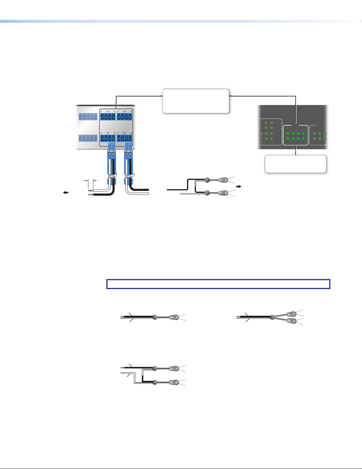
IR/Serial output ports (see figure 7 on page12) — An IPCP505 can use infrared
G
signals or unidirectional RS-232 serial signals to control various devices (up to 32 total
for IR) via these eight ports. Set output signal type (IR or serial) during configuration. The
figure below shows wiring examples.
IR/Serial Ports
Rear Panel Front Panel
1
2 3
4
SGSG
TX RXRT
OM8
TX
T
RT
IR/SERIAL
6
5
SGSG
SGSG
7
8
SGSG
Output options:
• IR (with or without carrier signals)
• unidirectional RS-232
RT
IR/S
CT
5162738
4
1
To Projector,
the Wired
IR Remote or
, or
IR or RS-232
Output
Ground
Strip wires
3/16"
(5 mm)
max.
Light when signals are transmitted
or
Unidirectional
IR
Ground
G
IR Output Signal
S
(-)
(+)
(-)
(-)
(+)
(+)
Two Single IR Emitters
IR Receiver
of a Projector,
Display, or
Source Device
on the corresponding IR/serial port
To the
Figure 11. Wiring the IR/Serial Ports
Serial control: Connect one of these ports to the serial control receive (Rx) and ground
pins of the device to be controlled. These ports have the same serial protocol options
as the COM ports (see page13 for protocol details).
IR control: Connect one of these ports directly to the wired IR port of another device.
Or insert the wires from up to four IR Emitters into an IR port and place the heads of the
emitters over or next to the IR signal pickup windows of the devices. For wiring, see the
following figures or the IREmitter Installation Guide (available on www.extron.com).
NOTE: Each emitter must be within 100 feet of the IPCP for best IR control results.
Installing One Single Emitter Installing One Dual Emitter
IR/S LEDs
Ground (−)
IR Signal (+)
One Single IR Emitter
Ground (−)
IR Signal (+)
Dual IR Emitter
Installing Two Single Emitters
When installing only single emitters, tie them in series as shown below.
Ground (−)
IR Signal (+)
(−)
(+)
(−)
(+)
Two Single IR Emitters
IPCP 505 • Hardware Features and Installation 15
Page 24
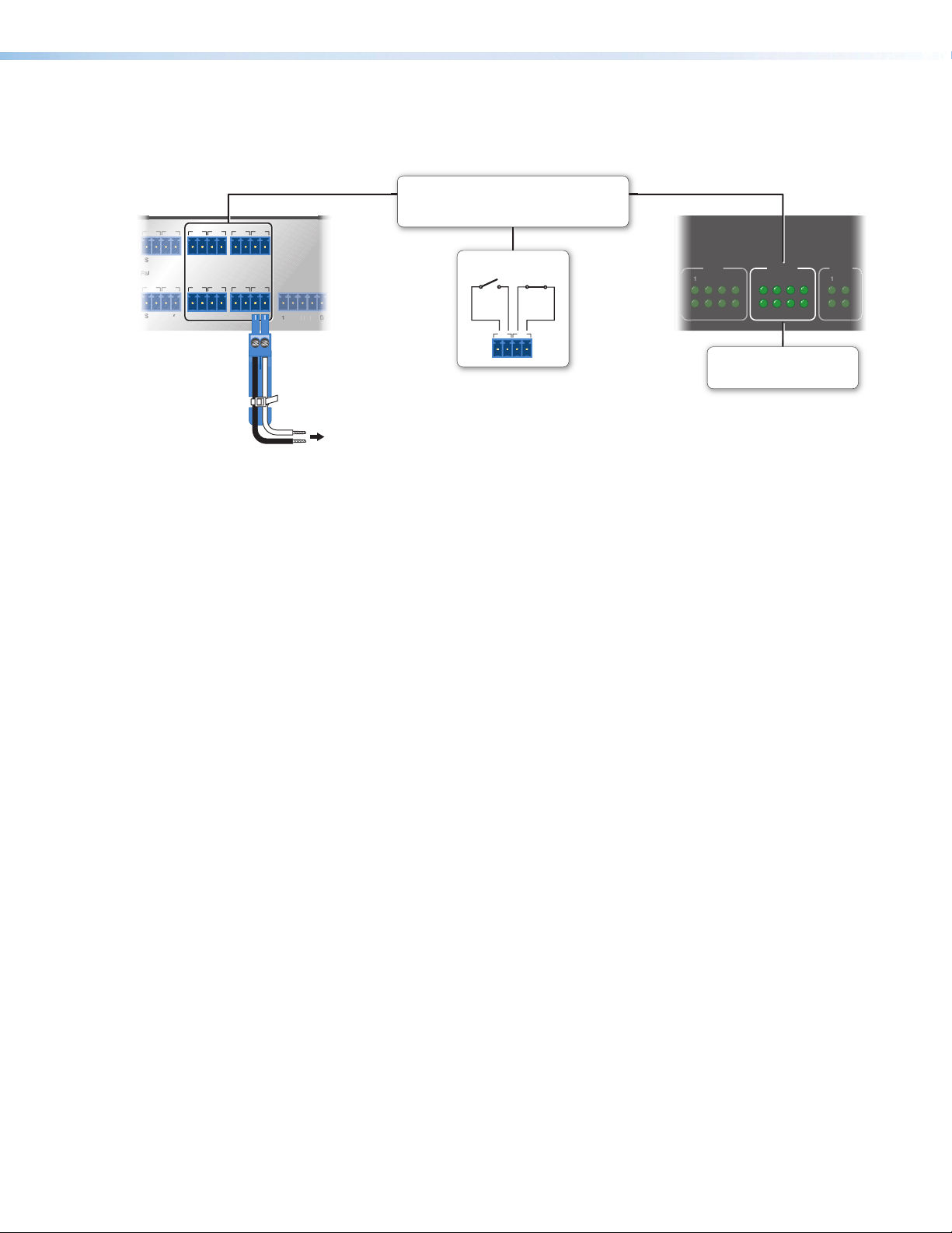
Relay ports (see figure 7 on page12) — Eight relay ports provide control for power,
3
L
3
S
4
S
8
SSEI
A
S
S
3
4
2
/S
5
6
2
3
8
4
H
screen/projector lifts, window coverings, and similar items, when trigger events occur.
Rear Panel Front Panel
1 2 3 4
G
RELAY
5 6
7 8
LEX I/O
To Room
Control
Equipment
• Connect devices for contact control.
• Do not exceed a total of 24V at 1A for each port.
Normally
Open
Closed
1 2
R
Light when the corresponding
relays are activated (tied to GND)
Figure 12. Wiring the Relay Ports
These relay contacts may be used to control any equipment as long as the contact
specifications of a total of 24volts at 1ampere are not exceeded for each port. These
relays are normally open by default.
When activated, the open contacts close. They can be set up to operate in one of two
ways:
• Latching (brief contact) (press to turn on, press to turn off), or
• Momentary (timed) (press to turn on, timeout to turn off).
In the timed mode the default timeout period is ½ second (500 ms). Use Global
Configurator software or SIS commands to change the length of the timeout period.
Relays
See the
X6#
variable on page67 and the corresponding relay port commands on
page66 in the SIS Programming and Control section for details.
RELAY
2
516
738
Relay LEDs
4
IPCP 505 • Hardware Features and Installation 16
Page 25
Additional Control Ports
MAC: 00-05-A6-XX-XX-XX
S/N:
3
4
8
5
6
2
3
8
4
Rear Panel Front Panel
1
Device 1
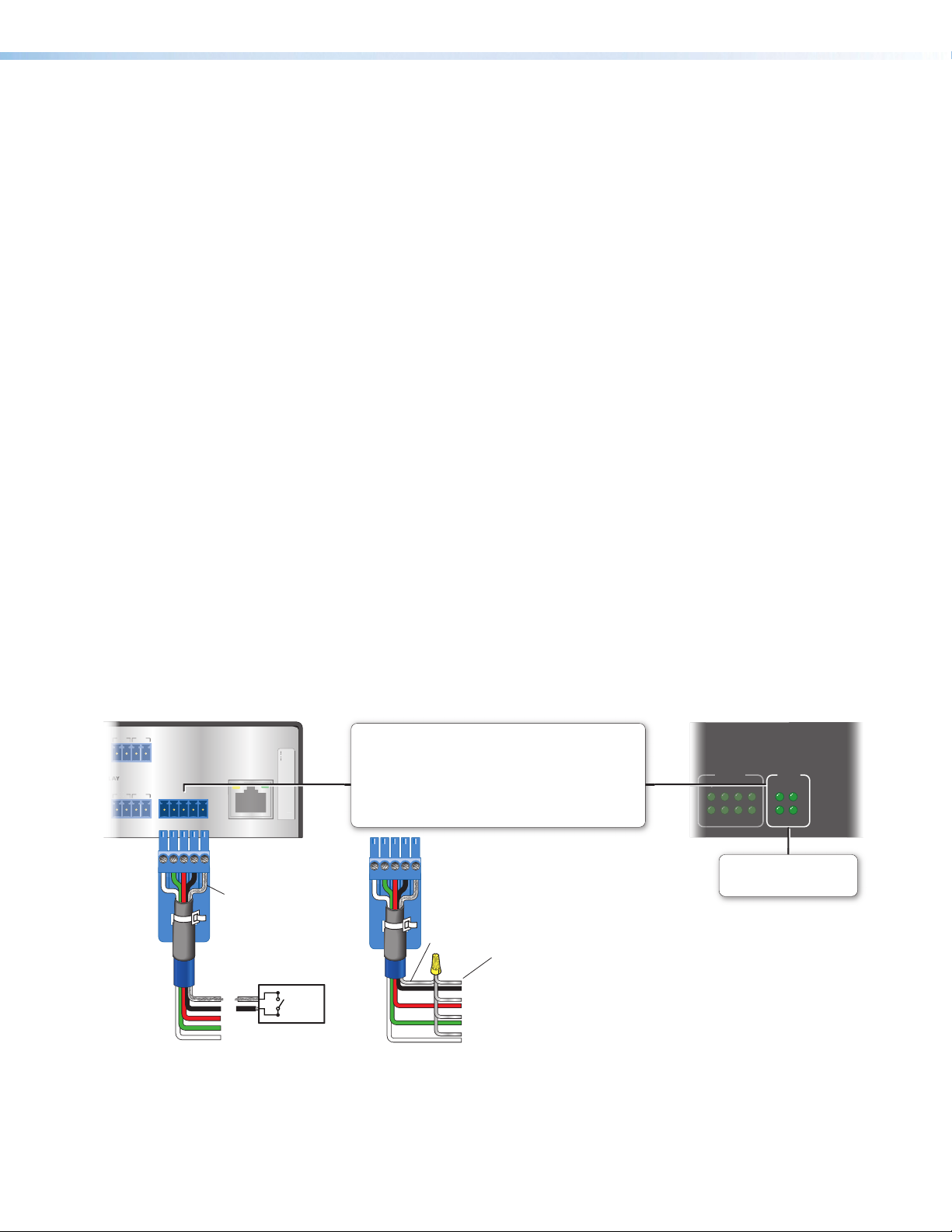
Flex I/O ports (see figure 7 on page12) —To allow the IPCP505 to monitor
I
devices to trigger events, connect switches, sensors, LEDs, relays, or similar items
to these four ports, which can be configured as analog inputs, or as digital inputs or
outputs, with or without +5VDC pull-up. These ports can trigger events or functions
(such as triggering relays, issuing commands, or sending an e-mail) that have been
configured using Global Configurator (GC) software.
Analog input — When a flex I/O port is configured as an analog input, the port can
measure 0 to 25.3 VDC with 12-bit accuracy. A DC level is indicated by a count from
0-4096 (≈ 6 mV per count).
Digital input — To allow the IPCP to monitor external devices that do not use RS-232
communication, connect a switch, motion sensor, moisture sensor, tally feedback
output, button pad, or a similar item to a flex I/O port and configure it for digital input.
When configured as a digital input, the port is set to measure two states: high and low.
The port accepts 0 to 12 VDC input. The threshold voltages are as follows: a voltage
below 2.0 VDC is measured as logic low, and a voltage above 2.8 VDC is measured as
logic high. There is also an internal, +5 VDC, selectable, pull-up resistor for this circuit.
Digital output — To activate LEDs, incandescent lights, or other devices that accept
a TTL signal, or to provide contact closure control for projector lifts, motorized screens,
room or light switches via an Extron IPA T RLY4, you can use one or more of these
ports as a digital output.
When a port is configured for digital output, it offers two output states: on and off.
• When the port is set to an “on” state, (the circuit is closed), the I/O pin is connected
to ground. Each I/O port is capable of accepting 250 mA, maximum.
• When the port is set to the “off” state (the circuit is open), the output pin is not
connected.
If the application calls for TTL compatibility, the digital output circuit can be set up to
provide a 2k ohm pull-up resistor to +5 VDC.
Flex I/O (digital input/output or analog input)
Congure each port as an analog input or as a digital input or
output, with or without +5 VDC pull-up.
Use these ports to:
FLEX I/O
1 234G
Heat
Shrink
Over
Shield
Wires
G
4
3
2
Switch,
Sensor
• Monitor or trigger events and functions (toggle relays, issue
commands, send e-mail), once congured.
• Power LEDs, incandescent lights, or other devices that accept
a TTL signal.
Ground
Wire
Nut
Share the same ground among
I/O connections.
Device 4
Device 3
Device 2
(Switches, sensors,
LEDs, relays, or
similar items)
Figure 13. Flex I/O Port Wiring Examples
IPCP 505 • Hardware Features and Installation 17
FLEX
I/O
2
314
7
Flex I/O LEDs
Light when the corresponding
ports are active
Page 26
Resetting the Unit
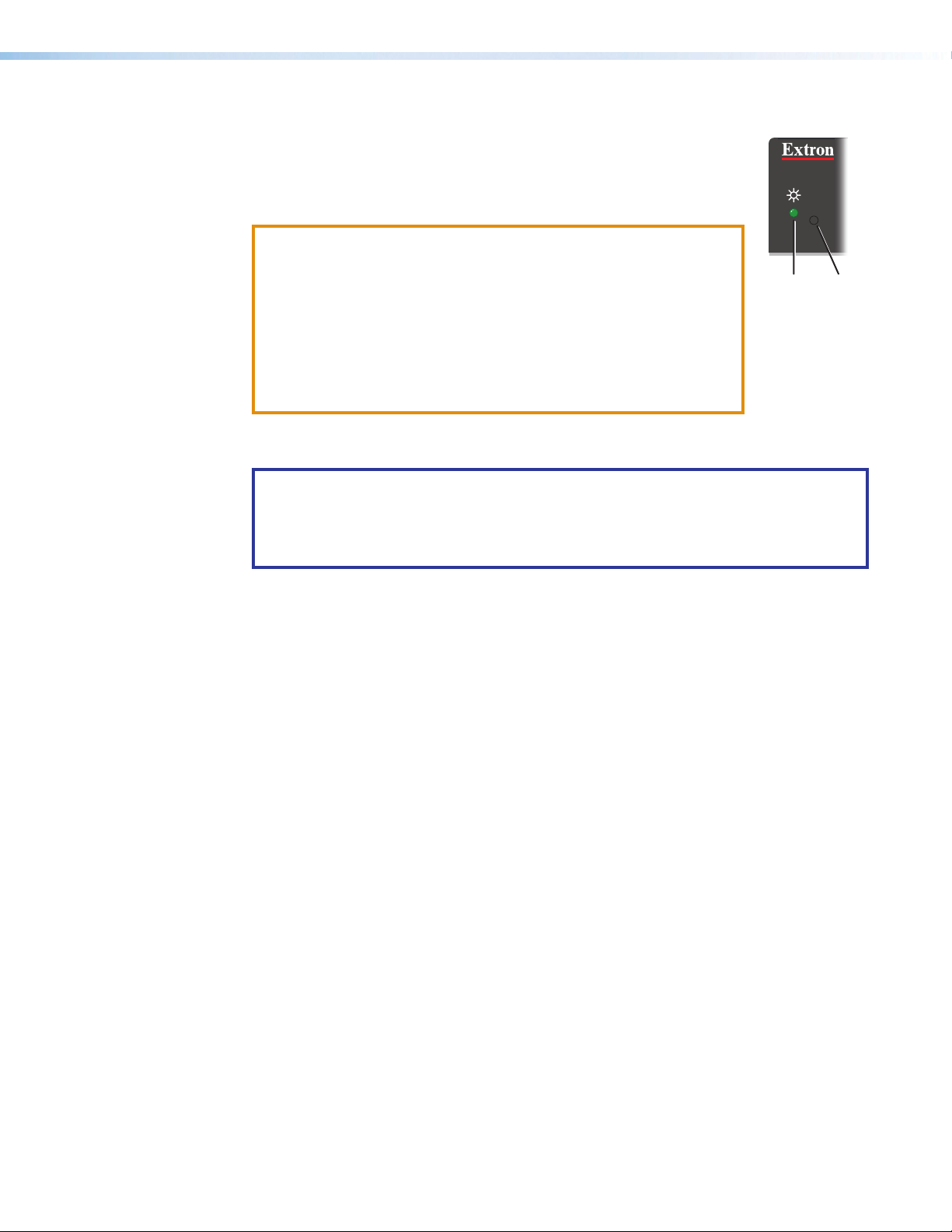
Reset
Button
There are five reset modes that are available by pressing the Reset
button on the front panel. The Reset button is recessed, so use a
pointed stylus, ballpoint pen, or Extron Tweeker to access it. See the
reset modes table on the next page for a summary of the modes.
ATTENTION:
The reset modes (with the exception of Mode 2) close all open IP and Telnet connections
and close all sockets.
NOTE: If you hold down the Reset button continuously, the LED blinks every 3seconds,
R
• Review the reset modes carefully. Using the wrong reset mode
may result in unintended loss of flash memory programming, port
reassignment, or an IPCP unit reboot.
Power
LED
• Analysez minutieusement les différents modes de réinitialisation.
[voir tableau page suivante]. Appliquer le mauvais mode
de réinitialisation peut causer une perte inattendue de la
programmation de la mémoire flash, une reconfiguration des
ports ou une réinitialisation du processeur.
and the unit enters a different mode, from Modes 3 through5.
For Mode5 (Reset to Factory Defaults) the LED blinks three times, the third blink
indicating the last mode. The modes are separate functions, not a continuation from
Mode1 to Mode5.
IPCP 505 • Hardware Features and Installation 18
Page 27

IPCP Controller Reset Mode Summary
Mode Activation Result Purpose and Notes
Hold down the recessed Reset button while
1
applying power to the IPCP.
NOTE: After a mode 1 reset is
performed, update the IPCP firmware to
the latest version. Do not operate the
IPCP control processor firmware version
that results from the mode 1 reset. This
mode temporarily resets the unit to
factory default until power is recycled.
If you want to use the factory default
Use Factory Firmware
firmware, you must upload that version
again. See the Global Configurator Help
File for firmware upload instructions.
The IPCP control processor reverts to the
factory default firmware. Event scripting does not
start if the unit is powered on in this mode. All user
files and settings such as drivers, adjustments, and
IP settings are maintained.
NOTE: If you do not want to update
firmware, or you performed a mode1 reset by
mistake, cycle power to the unit to return to
the firmware version that was running prior to
the mode 1 reset. Use the 0Q SIS command
to confirm that the factory default firmware is
no longer running (look for asterisks following
the version number).
Use mode 1 to revert to
the factory default version if
incompatibility issues arise
with user-loaded firmware.
NOTE: User-defined
web pages may not
work correctly if using
an earlier firmware
version.
Press and release the Reset button. Within 2
2
seconds enter +++ on the keyboard.
Enable SIS
Serial Console
Hold down the Reset button for about 3
3
seconds until the Power LED blinks once, then
release and press Reset momentarily (for <1
second) within 1second*.
Events
Run or Stop
Hold down the Reset button for about
4
6seconds until the Power LED blinks twice
(once at 3 seconds, again at 6seconds). Then,
release and press Reset momentarily (for
<1second) within 1second*.
Reset All
IP Settings
Hold down the Reset button for about 9
5
seconds until the Power LED blinks three times
(once at 3 seconds, again at 6seconds, again
at 9 seconds).
Then release and press Reset momentarily (for
<1second) within 1second*.
Reset to
Factory Defaults
NOTE: If the three “+”characters
(+++) are not entered in the 2-second
time frame, the COM port becomes a
control port only.
The connected COM port becomes a console
port to send SIS commands. Scripting remains on.
Mode 3 turns events on or off.
If the events are currently stopped following the
momentary press, the power LED flashes twice
indicating the starting of events.
If the events are currently running following the
momentary press, the Power LED flashes three times
indicating the stopping of events.
Mode 4:
• Enables ARP capability
• Sets the IP address back to factory default
(192.168.254.254)
• Sets the subnet back to factory default
(255.255.0.0)
• Sets the default gateway address to the
factory default (0.0.0.0)
• Sets port mapping back to factory default
• Turns DHCP off
• Turns events off
Mode 5 performs a complete reset to factory
defaults (except the firmware).
• Does everything mode 4 does
• Clears driver-port associations and port
configurations (IR and serial)
• Removes button/touchpanel configurations
• Resets all IP options
• Removes scheduling settings
• Removes/clears all files from the IPCP
controller
Mode 2 enables the SIS
console port.
Mode 3 is useful for
troubleshooting.
Mode 4 enables you to set
IP address information using
ARP and the MAC address.
Mode 5 is useful if you
want to start over with
configuration and uploading,
and also to replace events.
NOTES:
• *For modes 3, 4, and 5, nothing happens if the momentary press does not occur within 1second.
• After performing a Reset All IP Settings or Reset to Factory Defaults reset, set the IP address
again for use on your network.
• The factory configured password for this device has been set to the device serial number.
Passwords are case sensitive. Performing a Reset to Factory Defaults reset sets the password
to no password.
IPCP 505 • Hardware Features and Installation 19
Page 28

Software-based Configuration and Control
This section of the guide is divided into the following topics:
• Configuration and Control: an Overview
• Basic Setup Steps: a Guide to this Section and Other Resources
• Communicating with the IPCP
• Configuring the IPCP for Network Communication
• Global Configurator Software for Windows
• Advanced Configuration
• Controlling an IPCP505
• Controlling the IPCP505 with a Touchpanel
• Customizing the IPCP Control Web Pages
• Troubleshooting
Configuration and Control: an Overview
An IPCP505 must be configured before use in order to recognize and accept
commands and pass them on to the controlled devices. It can be configured and controlled
via a host computer attached to the LAN (local area network) port. See Hardware
Features and Installation starting on page8 for details about the port and cabling.
• The primary means for configuring the control processor is by using Extron
GlobalConfigurator (GC) software. This method requires a properly configured PC with
WindowsXP or a higher version of Windows installed. Global Configurator generates
GlobalViewer web pages that are uploaded to the IPCP and can be used to control the
unit and make adjustments to its settings.
NOTE: Microsoft Internet Explorer is currently the only web browser that fully
supports GlobalViewer pages.
• Alternatively the default web pages embedded within the IPCP505 provide a means
to perform some setup, adjustment, and control via a web browser (Internet Explorer
version 5.5+, or Mozilla® Firefox® version 1.0+) from any type of network-enabled
computer.
• The third way to control and configure the controller is by using Simple Instruction Set
(SIS) commands via Telnet (or a similar program), a web browser, or RS-232. SIS
commands are discussed in detail in SIS Programming and Control starting on
page53.
IPCP 505 • Software-based Configuration and Control 20
Page 29

Basic Setup Steps: a Guide to this Section and Other Resources
NOTE: Setup/configuration may be performed away from the job site.
1. Configure the IPCP for network communication (see Configuring the IPCP for
Network Communication on this page).
2. Download or install Global Configurator and other Extron software (IR Learner,
Firmware Loader, GUI Configurator, DataViewer) and device drivers (see the IPCP505
Setup Guide and the Extron website for instructions).
NOTE: The setup guide is shipped with the unit and is available at www.extron.com.
The setup guide and help files outline most of the common tasks required for setup.
3. Create a Global Configurator project and configure basic settings and
functions (see the Global Configurator Help file for step-by-step procedures).
4. Configure additional or advanced functions, if desired (see the GlobalConfigurator
Help File for step-by-step instructions). For information on IRlearning, see the
IRLearner Help File.
NOTE: If Extron TouchLink TLP touchpanels will be part of the system, you
also need to use GUIConfigurator to design and set up the interface for the
touchpanels, preferably before completing the IPCP configuration.
5. Save and upload the configuration to the IPCP.
6. Control the IPCP and devices connected to it by using the IPCP embedded web
pages, its GlobalViewer (GV) web pages, or a fully configured TLP touchpanel (see
Controlling an IPCP505 on page 38).
Communicating with the IPCP
To communicate with the IPCP505, you must power on the IPCP and the PC you will use
to configure it, and connect the two devices for IP (network) communication.
• Power: see page 8 for power input details.
• Communication: connect the IPCP to a network (see page 14). See “Configuring the
IPCP for Network Communication,” below, to set the unit up to talk with the PC.
Configuring the IPCP for Network Communication
Both the PC and the IPCP505 must be configured with the correct protocols and IP
addresses and connected to the same subnetwork.
When you power on the IPCP for the first time, you have a choice of several ways to set up
the IP address:
• Use the ARP (address resolution protocol) command.
• Use the Global Configurator software.
• Use a web browser.
• Use SIS commands via Telnet or a similar utility.
If you use a web browser or Telnet the first time you connect a PC to an IPCP via IP, you may
need to temporarily change the IP settings of the PC in order to communicate with
the controller (see Setting up the PC for IP Communication With an IPCP 505 on
page25). Then you must change the default IP address, subnet mask, and [optional]
administrator name and password of the controller in order to use the IPCP on a network.
After setting up the IPCP505 for network use, you can reset the PC to its original network
configuration.
IPCP 505 • Software-based Configuration and Control 21
Page 30
IPCP505 LAN port defaults:
• IP address: 192.168.254.254
• Gateway IP address: 0.0.0.0
• Subnet mask: 255.255.0.0
NOTE: Both the computer and the IPCP must be connected to the same subnet on a
LAN (using a straight-through cable). Alternatively, you can use a crossover Ethernet
cable to connect the controller directly to the Ethernet card in the computer.
The following instructions assume that you have already connected the PC to the LAN port
on the IPCP and powered on the controller and the PC.
• DHCP: off
• Link speed and duplex level: autodetected
Configuring the IPCP for Network Use Via Global Configurator
You can configure the IP address of the controller via an IP (Ethernet) connection using
Global Configurator (GC) software. See the Global Configurator Help File for basic
information on using the software and setting up a project. The “Add an IPCP505 and Set
the IP Address” topic in the help file provides step-by-step instructions on how to use GC to
set up the IP address of the IPCP.
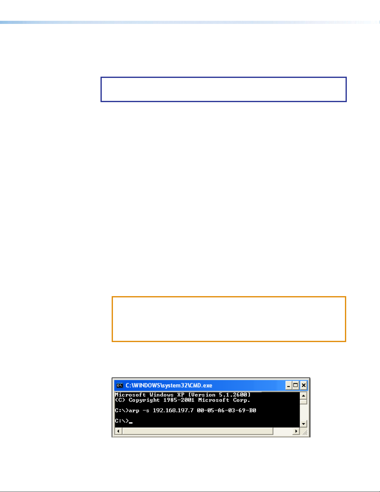
Configuring the IPCP for Network Use Via the ARP Command
The ARP (address resolution protocol) command tells the computer to associate the
MAC (media access control) address of the IPCP505 with the assigned IP address. You
must then use the ping utility to access the controller, at which point the IP address of the
controller is reconfigured.
Use ARP to configure the IP address as follows:
1. Obtain a valid IP address for the IPCP505 from your network administrator.
2. Obtain the MAC address (UID #) of the IPCP from the label on its rear panel. The MAC
address should have this format: 00-05-A6-xx-xx-xx.
3. If the IPCP has never been configured and is still set for factory defaults, go to step 4. If
not, perform a Mode 4 system reset. For detailed information on reset modes, see LAN
(IP) connector and LEDs starting on page14.
ATTENTION:
• The IPCP must be configured with the factory default IP address
(192.168.254.254) before the ARP command is executed.
• L’IPCP doit être configuré avec l’adresse IP par défaut (192.168.254.254) avant
d’exécuter la commande ARP.
4. To change to the new IP address, at the PC, access the command prompt, then enter
the arp –s command. Enter the desired new IP address for the unit and the MAC
address of the unit (listed on the rear panel, see page 14). For example:
arp –s 192.168.197.7 00-05-A6-03-69-B0
Figure 14. Sending the arp –s Command
After the arp -s command is issued, the controller changes to the new address and
starts responding to the ping requests, as described in the next step.
IPCP 505 • Software-based Configuration and Control 22
Page 31

5. Execute a ping command by entering “ping” followed by a space and the new IP address
at the command prompt. For example:
ping 192.168.197.7
You must ping the IPCP505 in order for the IP address change to take place. The
response should show the new IP address, as shown in figure 14.
Figure 15. Ping Command and Response Example
You can reconnect using either Telnet or a web browser to verify that the update was
successful.
6. Optional step: after verifying that the IP address change was successful, enter and issue
the arp –d command at the prompt. For example:
arp –d 192.168.197.7 removes 192.168.197.7 from the ARP table
or
arp –d* removes all static IP addresses from the ARP table.
IPCP 505 • Software-based Configuration and Control 23
Page 32

Configuring the IPCP for Network Use Via a Browser
The default web pages that are preloaded on the IPCP505 are compatible with popular
browsers such as Microsoft Internet Explorer (version 5.5 or higher) or Mozilla Firefox
(version 1.0 or higher). However, the IPCP and the PC must both be part of the same
subnet before they can communicate. You must change the IP address of the PC to one
that is on the same subnet as the default IP address of the IPCP505 (192.168.254.254).
NOTES:
• This method requires connecting the IPCP to the LAN port of the PC using a
crossover network cable (see cabling details on page 14).
• Make a note of the host TCP/IP configuration of the PC before changing its IP
address and make sure the PC and IPCP are on the same subnet.
1. Temporarily change the IP address of the host PC. See Setting up the PC for IP
communication with an IPCP505 on page 25 for step-by-step instructions.
2. Obtain a valid IP address for the controller from your network administrator.
3. Launch the web browser on the connected PC (for which you set up the network
configuration earlier), and enter http://192.168.254.254/ in the address box. The
default web page of the IPCP505 is displayed.
4. Select the Configuration tab (see figure 16, 1).
5. Select System Settings from the menu on the left of the screen (2). A web page
appears.
Figure 16. Configuring for Network Use Via the System Settings Embedded
Web Page, Steps 4 Through 7
6. Set the IPCP for the new IP address using only one of the following options:
• Enter the new IP address for the IPCP505, the corresponding subnet mask, and
the gateway address (3). IP addresses and subnet masks follow standard naming
and numbering conventions. The IP network administrator should provide the IP
addresses and subnet mask to be used with this controller.
• Select DHCP On (4).
7. Click Submit (5). It takes a minute or more for the controller to store the new settings.
Once the IP address of the controller is changed, you lose communication with the
controller.
8. Close the browser.
9. After changing the IP settings of the controller, change the TCP/IP settings of the PC
back to their original configuration.
IPCP 505 • Software-based Configuration and Control 24
Page 33

Configuring the IPCP for Network Use Via SISCommands and Telnet
The IPCP and the PC must both be part of the same subnet before they can communicate.
Change the IP address of the PC to one that is on the same subnet as the default IP
address of the IPCP505 (192.168.254.254).
NOTES:
• This method requires connecting the IPCP to the LAN port of the PC using a
crossover network cable (see cabling details on page 14).
• Make a note of the host TCP/IP configuration of the PC before changing its IP
address and make sure the PC and IPCP are on the same subnet.
1. Temporarily change the IP address of the host PC. See “Setting up the PC for IP
communication with an IPCP505” below for step-by-step instructions
2. Start Telnet on the PC:
a. Click the Start menu and select
Run. The Run dialog box
appears, as shown at right.
b. Enter telnet, a space,
and the default IP address
(192.168.254.254) into the Open
field, and click OK.
3. Set the IPCP to the new IP address by doing one of the following.
• Enter SIS command E
Programming and Control section starting on page 53) to set the IP address.
• Enter SIS command 1DH} to enable DHCP.
4. After changing the IP address of the IPCP controller, change the TCP/IP settings of the
PC back to their original configuration.
X1$ CI}, where X1$ is the new IP address (see the SIS
Setting up the PC for IP Communication With an IPCP505
You need a Windows-based (Windows 2000, Windows XP, or higher) PC equipped with an
operating network adapter. For your PC to work with Extron Ethernet-controlled products,
the TCP/IP protocol must be installed and properly configured, and you must change the
IP address of the PC to one that is on the same subnet as the IPCP.
If you use an existing Ethernet LAN intranet, your network administrator can provide you
with a unique IP address for the controller or confirm whether you need to set up the
IPCP505 for DHCP (Dynamic Host Configuration Protocol) to have an address assigned
automatically when you sign on.
IPCP 505 • Software-based Configuration and Control 25
Page 34

1. Open the Network Connections page as follows:
• Locate and right-click on My Network
Places on the Windows 2000,
WindowsXP (or higher version) desktop,
then click on Properties. (see image
at right, 1)
or
• Click on the Start menu, click on Settings (if needed),
click on Control Panel to open the Control Panel window, and double-click on
Network and Dial-up Connections (Windows 2000), Network Connections
(Windows XP, shown below),
or Network and Sharing Center (Windows 7, shown below).
2. Access the properties dialog box.
• For Windows XP, right-click on Local Area Connection, then select
Properties.
• For Windows 7, click on Local Area
Connection to open the Local
Area Connection Status dialog
box, then click Properties.
IPCP 505 • Software-based Configuration and Control 26
Page 35

3. Select Internet Protocol (TCP/IP) (figure 17, 1) and click on the Properties
button (2), as shown in figure 17 below for Windows XP (left) and Windows 7 (right). If
Internet Protocol (TCP/IP) is not on the list, it must be added (installed). See the
Microsoft Windows user manual or the Windows online help system for information on
how to install the TCP/IP protocol.
Figure 17. Selecting Internet Protocol (TCP/IP) For the LAN Connection
4. Write down the current IP address and subnet mask of the PC below. If your PC is set
to “Obtain an IP address automatically,” make a note of that, instead. You will need to
restore these settings to the PC later.
IP address:
. . . .
Subnet mask:
. . . .
IPCP 505 • Software-based Configuration and Control 27
Page 36

5. Change the IP address of the PC so it can communicate with the IPCP, and change the
IP settings of the controller.
a. Click the Use the following IP address button (see figure 18, 1).
b. Enter the following values, as shown in the following pictures for WindowsXP (left)
and Windows7 (right) (2):
IP address:
Subnet mask:
Default gateway:
192.168.254.253
255.255.0.0
blank or 0.0.0.0
Figure 18. Step 5: Changing the IP Address of the PC
c. Click the OK button (3) to save the changes and exit the network setup. Reboot
the PC, if required, for the changes to become effective.
6. Plug one end of a CAT5 Ethernet crossover cable into the LAN connector on the IPCP
(see RJ-45 LAN connector wiring on page 14). Plug the other end of the Ethernet
cable into the Ethernet port on the PC.
NOTE: If a network hub or switch is used between the PC and the IPCP, use a
straight-through CAT 5 cable instead of a crossover cable (see pin assignments
on page 14).
7. Set up the IP address of the IPCP using a web browser, or the same SIS commands as
described earlier in this section.
8. Restore the previous IP configuration of the PC by following steps 1, 2, 3, and 5, but
use the original IP address settings for the PC that you wrote down in step 4.
IPCP 505 • Software-based Configuration and Control 28
Page 37

Global Configurator Software for Windows®
The Global Configurator (GC) program for Windows offers the best, most complete way to
configure and customize the controller. GC provides the ability to generate a browser-based
GlobalViewer (GV) application and web pages for each IP Link-based device (IPCP505,
IP Link control processor, System 5 IP, MLC 226 IP, MLC 104 IP Plus, or other Extron
device) on a network. Once an IPCP505 is configured, its GlobalViewer web pages allow
the user to manage, monitor, and control the IPCP and the devices connected to it.
Other setup options include using SIS commands and the factory-embedded web pages,
but many setup features are available only via Global Configurator. GC includes some
functions found on the embedded web pages of the controller and many additional features
that are available only through the software.
Downloading the Software and Getting Started
Global Configurator software updates and a large variety of device drivers can be
downloaded at no charge from the Extron website (www.extron.com). When you locate
the desired software or driver package, follow the on-screen directions to download and
install it.
NOTES:
• Ethernet, serial, and infrared (IR) device drivers (for controlling projectors, VCRs,
Blu-ray players, DVD players, and so forth) are available on the Extron website:
• As individual device driver files
• As an IP Link driver package.
If an IR driver does not already exist for an IR-controlled device in your system,
you can download the optional IR Learner. It is a free software utility that makes it
possible to capture infrared codes from a handheld IR remote control and create
custom drivers for operating the corresponding IR-controlled device.
• Do not change the directory or the name of the directory where the software files
are installed by default.
Read the Global Configurator Help File for details and step-by-step procedures on how
to start a GC project and perform basic setup tasks for an IPCP. The help file contains
instructions on how to set the following items so that the IPCP505 is able to communicate
with the network:
• IP address
• gateway IP address
• subnet mask
Obtain this information from your network administrator and set the IP address before
continuing.
PC System Requirements
See System Requirements on page7 for the minimum hardware and software
requirements.
NOTE: The IPCP505 requires GC version 3.2 or higher.
• mail server IP address
• domain name
IPCP 505 • Software-based Configuration and Control 29
• Telnet port
• web port
• SMTP username
• SMTP password
Page 38

Using Global Configurator: Helpful Tips
Resources and Notes
• The IPCP505 Setup Guide is shipped with the unit, and it covers how to install the
software and lists other available resources (software, drivers, instructions). It includes
a quick reference to the front and rear panel features, and covers basic hardware
installation and how to set the IP address of the unit using the ARP command.
• The Global Configurator Help File provides information on settings and how to use the
Global Configurator program, itself. This help file, included with the software, covers
basic setup steps and includes examples of how to use the basic tabs in GC and step
by step instructions for typical configuration tasks.
• See Front Panel Features on page10 and Rear Panel Features and
Connections on page12 for features and settings for the ports you will configure in
GC.
• If you will configure the IPCP at the installation site, Extron recommends using the driver
subscription function within Global Configurator to download drivers for all manufacturer
and device types before you go out into the field.
• The Global Configurator project file (*.gc2 or *.gcz) contains configuration settings and it
can be saved to a directory or folder for backup or for installation on another IPCP505
controller. Saving a configuration is recommended before you perform a firmware
upgrade.
• Global Configurator 3 is capable of loading all GC2 project files from GC version 2.0.3.3
and up. GCZ files can be opened by clicking File > Open, by clicking the toolbar icon,
or by double-clicking on the GCZ file. GC2 and GCC files must be imported, however.
• The IPCP can be set up to allow configuration access only to administrators to prevent
other users from making changes to settings, events, and controls. If an administrator
password is set for the controller, non-administrator users can select inputs, adjust
volume, and trigger some other device commands from the GlobalViewer Control pages
but are prevented from making any other changes using GlobalViewer web pages.
• IP addresses, subnet mask, and e-mail addresses follow standard naming and
numbering protocol. The network administrator provides the IP addresses and subnet
mask to be used with this controller.
• The unit name is any name (for example, Room107-IPCP505, Lab1234control,
ConfRmSystem) that you want to use to label a specific IPCP505 unit. The default
is a combination of the product name and part of the hardware address. This can be
changed to your choice of alphanumeric characters and hyphens (-).
• Spaces are not permitted within the name of a unit.
• Underscores (_) are not permitted.
• Valid characters are A-Z, a-z, 0-9, and - (hyphen).
• The name cannot start with a number or a hyphen, and it cannot end with a
hyphen.
• Maximum name length is 24 characters.
IPCP 505 • Software-based Configuration and Control 30
Page 39

A Brief Guide to Tabs in Global Configurator
In the upper right side of the GC window are several tabs that divide the program into
groups of functions you can view and configure. The left three, IP Link Settings,
Schedule, and Monitor, are displayed for all IP Link-enabled products. Tabs to the right
of those three vary in quantity, type, and layout, depending on the product and ports being
configured. The following figures show tabs that may be available when you configure an
IPCP505.
Common IP Link Functions IPCP- and Port-specific Functions
Figure 19. Tabs That May Be Available in Global Configurator
To learn about the functions available on each of these tabs, see the Global Configurator
Help File. In the contents pane on the left, click on Reference Information, click Global
Configurator Window, then click on the name of the tab you want to know more about.
Advanced Configuration
IR Learning to Create Customized IR Driver Files
If you do not find a driver on the Extron website for the device you plan to use, you can
create your own IR driver file. Extron IR Learner software lets you create a customized driver
file of IR commands that can be used with the Global Configurator software for port setup
and button configuration. Visit www.extron.com to download IR Learner and install it on
your PC.
NOTE: The IPCP505 requires IR Learner version 1.24 or higher.
Once IR Learner is installed on the PC, you can start the program directly
by double-clicking the IR Learner icon, shown at right.
Alternatively, you can select Run IR Learner from the Global Configurator
Tools menu, as shown at right. The IR Learner
utility opens in a new window.
See the IR Learner Help File for instructions
on how to create the driver file. During IR
command capture, hold the IR remote for the
device so that it faces the IR learning receiver (on the IPCP front panel) within the angles and
distance range shown in the front panel diagram on page10.
IPCP 505 • Software-based Configuration and Control 31
Page 40

Printing a Wiring Block Diagram or a GUI Configuration Report
Once you have configured a system using Global Configurator, you can generate and print
a simple block diagram of what products to wire to which of the ports on the IPCP505. The
diagram includes model names and the type of communication (IR or RS-232) configured
for each port. For more detailed information, in the Global Configurator Help File, read about
the File menu within the “Reference Information” section.
NOTE: This procedure requires Microsoft Word software (for a block diagram) or an
internet browser application (for a GUI configuration report). The installer or user must
provide that software. They are not Extron products.
Procedure overview:
1. In Global Configurator, click on the File drop-down menu and select Print and then
Wiring Diagrams/GUI Configuration Report.
2. In the Print Wiring Diagrams/GUI Configuration Report window, select the
devices to include in the diagram.
3. Click the Print Wiring Diagrams button or the Print GUI Report button.
GC processes the information about the selected device(s), generates a document
containing the wiring diagram or report, and opens that document in Word (for the
diagram) or in a browser window (for the GUI report).
To see an example of a wiring diagram, click here to open the Attachments area to the
left of this page, then double-click on the name of the attached PDF file. The file opens
in a new window.
4. Print the diagram or diagrams and, if desired, save the file or files. Exit Word or the
browser.
5. Close the Global Configurator Print Wiring Diagrams/GUI Configuration
Report window.
Updating Firmware
If the need arises, you can replace the firmware of the IPCP without opening the unit or
changing firmware chips. See the Firmware Updates section starting on page 81 for
instructions on how to update the firmware for the controller.
NOTE: Save the existing GC configuration project before replacing the firmware.
IPCP 505 • Software-based Configuration and Control 32
Page 41

Advanced Serial Port Control
Serial Pass-through (redirect)
If serial setup configurations are required, the following options provide more advanced
methods for serial configuration within the IPCP:
• Serial pass-through (or redirect mode) (page 34) — to pass a control signal in one
serial port on the IPCP and out through another serial port on the same IPCP
• Direct port access (page 34) — to pass a control signal through a Telnet
connection on the IPCP to an AV device connected to an IPCP serial port
• Serial bridging (page 35) — to pass a control signal into a serial port on an originating
IPCP (or IPL) through a network and out a specified serial port of a destination IPCP (or
IPL) to a connected AV device
IPCP 505
COM
(serial)
port
RS-232
PC or
Third Party
Device
Direct Port Access
Serial Bridging
PC or
Third Party
Device
RS-232 RS-232
PC or
Third Party
Device
IPCP 505
(unit 2)
COM
(serial)
port
TCP/IP
Network
Ethernet Ethernet
LAN
port
TCP/IP
Network
EthernetEthernet
Figure 20. Methods of Advanced Serial Port Control
IPCP 505
LAN
port
IPL T,
IPL 250,
or IPCP
(unit 1)
LAN
port
COM
(serial)
port
COM
(serial)
port
COM
(serial)
port
RS-232
RS-232
Display
or Other
AV Device
Display
or Other
AV Device
Display
or Other
AV Device
IPCP 505 • Software-based Configuration and Control 33
Page 42

Serial pass-through (redirect mode)
Serial pass-through allows serial commands from a controller to “pass through” an
IPCP505 on route to an AV device. Any serial port on an IPCP can be configured as a passthrough connection to another serial port on the same device. For example, an RS-232
control device connected to the COM1 port on an IPCP505 could control a projector
connected to the COM2 port. COM1 passes through (redirects) the serial signal to COM2 in
that example.
Serial pass-through is enabled or disabled through the COM Configuration tab within Global
Configurator (see figure 21, 1), in the Pass Through Configuration pane (2) as
shown below and as described in the GC help file.
Figure 21. A Global Configurator Screen Showing Serial Pass-Through
Configuration
Advanced users can use the pass-through SIS command as well (see the Simple Instruction
Set CD commands on page 63 for detailed command descriptions).
Direct port access (ports 2001 through 2016)
Direct port access allows a direct, one-to-one connection to any one of the IPCP serial
ports using a TCP/IP connection. When a TCP session is initiated to a COM port, all data
sent and received passes directly to and from that port without any processing. Set serial
port parameters (baud rate, parity, data bits, stop bits) within the IPCP prior to using direct
access.
NOTES: The reserved TCP port numbers (2001-2016) are assigned by default as
follows:
Bidirectional ports:
2001 = COM1 2005 = COM5
2002 = COM2 2006 = COM6
2003 = COM3 2007 = COM7
2004 = COM4 2008 = COM8
You can use SIS commands (see page 72) to assign a different range of port
numbers to these ports, if needed.
An IR/serial port must be configured for serial communication to be used for direct port
access.
Unidirectional ports:
2009 = IR/Serial 1 2013 = IR/Serial 5
2010 = IR/Serial 2 2014 = IR/Serial 6
2011 = IR/Serial 3 2015 = IR/Serial 7
2012 = IR/Serial 4 2016 = IR/Serial 8
IPCP 505 • Software-based Configuration and Control 34
Page 43

To initiate direct port access using Extron DataViewer software:
M
C
00
05
6
200
RS-232 Enabled
r
200
1. Connect the IPCP505 to a network.
2. If necessary, use GC (see the help file for details), the Port Settings embedded
web page (see page 42), or SIS commands (see page 62) to set serial port
parameters (baud rate, parity, stop bits) for the IPCP505 COM port to be used.
3. Launch the DataViewer program.
4. Click File > Connect to open the Communication Setup dialog box.
5. Click the TCP/IP tab.
6. Complete the fields with the IP address of the IPCP505 and the TCP/IP port number
(2001, 2002, 2003,...) of the COM port (on that same IPCP unit) that will be used, as
shown below.
NOTE: A password is not required for direct port access.
AV Device
Rev. C:
Updated
IP address
from
10.13.x.x to
192.168.x.x.
RS-232
2002
2003 2007 2009 2010 2011 2012
COM1
COM2
COM3
1
TX RX
GGG
TX RX
COM5 COM6 COM8
COM4
4
GG
TX RX
TX RX
2005 2006 2008
TX RX
TX RX
COM7
TX RX
G
TX RX
1
SGSG
G
CTS
RTS
5
SGSG
G
CTS
RTS
2013 2014
2 3
IR/SERIAL
6
4
SGSG
7
8
SGSG
PC
2016
2015
LAN
IPCP Rea
Panel
Ethernet
TCP/IP
Network
S/N:
A
:
-
-A
-XX-XX-XX
Figure 22. DataViewer Communication Setup Dialog Box and Direct Access Wiring
7. Click OK. The DataViewer commands window opens.
8. Enter SIS commands into the Commands area of the window to send those commands
directly to the attached AV device through the selected COM port.
9. To end the direct access session, close DataViewer.
Serial bridging
Serial bridging mode creates a virtual serial connection (a “bridge”) between two IPCP or IPL
units (or an IPCP and an IPL unit). This allows serial data to be passed over a shared LAN
to devices connected via the COM ports on the IPCP. To use serial bridging, two IPCP or
IPL devices (one local and one remote) must be enabled to communicate with each other,
establishing PC, touchpanel, or controller access to a remote AV device.
IPCP 505 • Software-based Configuration and Control 35
Page 44

Hardware connection
Extr
IPL T S4
Contr
(unit 1)
ol and
222222
333333
444444
To set up the hardware for serial bridging:
1. Verify that the protocol (baud rate, data bits, stop bits, parity) is identical for both serial
ports that will be “bridged” (one port on each IPCP or IPL unit).
2. For unit 1 (the remote IPCP or IPL device), connect a serial cable to an AV device such
as a display or projector (see figure 23, 1).
3. Connect that same remote IPCP or IPL (unit 1) to the LAN (see 2).
on
ol Processor
UID# 093012052
POWER
12V
.5A MAX
Plasma Display
COM 3
COM 2
COM 1
COM 2
LAN
RS-232
11111111
Extron
IPCP 505
IP Link®
Control Processor
(unit 2)
COM3
COM2
G
COM1
TXRX
G
2
TXRX
G
COM6
1
RX
TX
COM5
G
COM4
TXRX
+- + -
G
100-240V 50-60Hz
4
TXRX
SWITCHED 12VDC
G
40W MAX TOTAL
3
TXRX
+- + -
MAX
5A
Ethernet
4
Ethernet
2
2
TCP/IP
Network
4
3
3
4
3
2
1
FLEX I/O
4
3
G
8
RELAY
7
2
1 2 3 4
1
6
S G S G
5
G
COM7
8
S G S
IR/SERIAL
7
6
RTS CTS
G
5
TXRX
S G S G
COM8
S G S G
RTS CTS
G
TXRX
RS-232
Remote User Contr
Administrator Monitoring
Figure 23. Connections for Serial Bridging
4. For unit 2 (the local IPCP or IPL device), make a serial connection to the PC or controller
that is to control the remote AV device (see 3).
5. Connect the local IPCP or IPL device (unit 2) to the same network (see 4).
You are now ready to configure unit 2 (the local IPCP or IPL device) for serial bridging mode.
Serial bridge configuration
To allow both units to communicate together, you must configure unit 2 to communicate
with unit 1.
NOTE: If a serial (RS-232) driver was previously loaded (via Global Configurator) onto
the IPCP unit, serial bridging disables it.
LAN
To configure unit 2:
1. Enter the IP address of unit 2 in the browser Address field at the top of the screen, and
press the <Enter> key. The System Status page opens, showing the current IP and
serial port settings of unit 2.
IPCP 505 • Software-based Configuration and Control 36
Page 45

2. Access the web server port setting screen by clicking the Configuration tab then
the Port Settings link on the left side of the window (see figure 24, 1). The Port
Settings page appears, as shown in figure 24.
Figure 24. Port Settings Internal Web Page for Unit 2
3. Choose the serial port (on the local IPCP505, unit 2) through which you wish to
communicate (2).
4. For serial bridging, click the On radio button to activate bridging mode (3).
5. In the Remote IP Address field, enter the IP address of unit 1 (the remote device) (4).
6. In the Remote TCP Port field, enter the number of the serial port number on unit1 for
this virtual connection (5).
• For an IPCP505, choose a port number from 2001 (COM1) - 2016 (IR/serial port8),
as noted on page 34 in the direct port access section of this guide.
• For an IPL 250 or IPL T S Series control processor, choose from 2001 (COM1) -
2006 (COM6), based on the available COM ports (see figure 25).
PC or
Third Party
Device
IPCP 505
(unit 2)
COM
RS-232 RS-232
(serial)
port
Ethernet Ethernet
LAN
port
TCP Port Numbers (2001-20nn) for
IPCP and IPL Serial Ports
Bidirectional ports Unidirectional ports
Number Port Number Port
2001 COM1 2009 IR/Serial 1
2002 COM2 2010 IR/Serial 2
2003 COM3 2011 IR/Serial 3
2004 COM4 2012 IR/Serial 4
2005 COM5 2013 IR/Serial 5
2006 COM6 2014 IR/Serial 6
2007 COM7 2015 IR/Serial 7
2008 COM8 2016 IR/Serial 8
TCP/IP
Network
IPL T Sn, IPL 250,
or IPCP
LAN
port
(unit 1)
COM
(serial)
port
Display
or Other
AV Device
Figure 25. Serial Bridging System Diagram and Port Numbers
7. Click the Submit button (see figure 24, 6). The AV device attached to remote unit 1
should now accept all serial commands from your PC, touchpanel, or controller.
IPCP 505 • Software-based Configuration and Control 37
Page 46

Saving and Uploading the Configuration
This is not an advanced configuration function, but when you finish creating the
configuration in Global Configurator, you must save the GC project and upload the
configuration to one or more IPCP505 units (see the Global Configurator Help File for
instructions).
Controlling an IPCP505
You can control the IPCP and devices connected to it by using a shared network and one or
more of the following tools:
• The factory-embedded web pages within the IPCP
• The GlobalViewer (GV) web pages that are created when you upload the GC
configuration to the IPCP
• A TouchLink touchpanel with a customized graphical user interface (GUI), provided that
the TouchLink is included in the IPCP505 configuration
Embedded Web Pages
The IPCP505 features an embedded web server, which includes factory-set web pages.
These pages can be replaced with user-designed files, but the default web pages provide
many basic features for monitoring, configuring, and controlling the unit via a web browser.
This section provides an overview of these web pages, which provide some of the features
of the configuration program.
To access the embedded web pages,
1. Launch a web browser (Internet Explorer, Mozilla Firefox) on the connected PC, enter
the IP address of the IPCP in the address field, and press the <Enter> key.
NOTE: After GlobalViewer web pages have been uploaded to the IPCP, the GV
web pages open by default (instead of the factory-set web pages) if you enter
just the IP address (such as 192.168.197.7 or http://192.168.197.7) of the
IPCP unit. To view the factory-set web pages on a GV-enabled IPCP unit, add
/nortxe_index.html after the IP address before pressing <Enter>.
For example, enter http://192.168.197.7/nortxe_index.html.
2. In the Connect to {IP address} or
Windows Security dialog box, shown
at right, enter the IP address of the IPCP
or text of your choice in the User Name
field, enter the administrator password
in the Password field, and click OK. The
IPCP default web page appears.
If the IPCP has not already been
configured with a password, this
password dialog box does not appear;
the default web page opens directly.
NOTES:
• Passwords must contain 4 to 12 alphanumeric characters. Symbols and
spaces are not allowed, and the passwords are case sensitive.
• Administrators have access to all of the web pages and are able to make
changes to settings. Users can access the System Status page only.
IPCP 505 • Software-based Configuration and Control 38
Page 47

Status
The Status web page provides only settings information. Changes must be made via
the Configuration web page, the Global Configurator software, or SIS programming.
Personnel who have user access can view the Status page but do not have access to
configuration pages.
IPCP 505 • Software-based Configuration and Control 39
Page 48

System Status
The System Status page provides information about the IPCP505 model, part number,
firmware version, port and IP settings, as shown in the following example. This information is
useful when troubleshooting.
Figure 26. A System Status Embedded Web Page
IPCP 505 • Software-based Configuration and Control 40
Page 49

Configuration
There are six Configuration web pages tabs, which only administrators can access:
• System Settings
• Port Settings
• IR Drivers
• Passwords
• Email Alerts
• Firmware Upgrade
System Settings
This page is for IP and date/time setting changes. Click Configuration (see figure 27, 1)
and System Settings (2) to open the page.
Figure 27. A System Settings Embedded Web Page
NOTE: The unit name can be changed to one of your choice using up to 24
alphanumeric characters and hyphens (-). See Using Global Configurator: Helpful
Tips on page 30 earlier in this section for examples.
• Spaces ( ) and underscores (_) are not permitted within the name of an IPCP unit.
• Valid characters are A-Z, a-z, 0-9, and - (hyphen).
• The name cannot start with a number or hyphen. It cannot end with a hyphen.
IPCP 505 • Software-based Configuration and Control 41
Page 50

Port Settings
This page allows limited changes to serial (COM) port, IR/serial port, and flex I/O port
settings, and to the on/off status of each relay port. It also permits control and grouping of
the switched 12 VDC power output ports. Click Configuration (see figure 28, 1) and
Port Settings (2) to open the page.
Figure 28. A Port Settings Embedded Web Page
IPCP 505 • Software-based Configuration and Control 42
Page 51

IR Drivers
Once the IPCP505 is configured and IR drivers have been uploaded to the unit and
linked to specific IR ports, you can view a list of the uploaded drivers using this page. Click
Configuration (see figure 29, 1) and IR Drivers (2) to open the page.
Click on the name of the driver file (3) to switch to a view of the commands loaded for that
driver. Clicking on a port and then a command name makes the IPCP send that command
out its linked IR port to the connected device.
Figure 29. An IR Drivers Embedded Web Page
IPCP 505 • Software-based Configuration and Control 43
Page 52

Passwords
In the Passwords page you can change the administrator and/or user passwords.
Figure 30. A Passwords Embedded Web Page
NOTES:
• Passwords must contain 4 to 12 alphanumeric characters. Symbols and spaces are
not allowed, and the passwords are case sensitive. A minimum of four characters
are required when creating passwords via the web pages.
• A user password cannot be assigned if an administrator password does not exist.
• If the administrator password is cleared, the user password is also cleared.
Email Alerts
In this page you can specify the IP address and domain name of the web server, set up
SMTP verification credentials, and specify the addresses of e-mail alert recipients and which
e-mail file they will be sent.
Figure 31. An Email Alerts Embedded Web Page
IPCP 505 • Software-based Configuration and Control 44
Page 53

Firmware Upgrade
Through this page you can locate and load new firmware to the unit.
Figure 32. A Firmware Upgrade Embedded Web Page
NOTES:
• See Firmware Updates starting on page81 for instructions on how to update
the firmware.
• Save the existing configuration project before replacing the firmware.
IPCP 505 • Software-based Configuration and Control 45
Page 54

File Management
This web page allows you to sort by file type (see the Filter by File Extension
drop-down list, 1). Personnel with administrator access can view these pages and make
changes. Those with user-level privileges are not able to see this page. For an explanation of
file types see File Types: a Key to Extron-specific File Names on page80.
Figure 33. A Typical File Management Page with Filtering by File Extension
ATTENTION:
• Files with the .cdc extension (___.cdc files) should NOT be deleted.
• Les fichiers contenant l’extension .cdc (fichiers __.cdc) NE doivent PAS être
supprimés.
• Potential for product malfunction. Event files (__.evt) should NOT be deleted.
They are necessary for operation of the controller. Never delete the main event file
(0.evt).
• Les fichiers Événement (__.evt) NE doivent PAS être supprimés. Ils sont nécessaires
au fonctionnement du contrôleur. Ne jamais supprimer le fichier Événement
principal (0.evt).
IPCP 505 • Software-based Configuration and Control 46
Page 55

You can also view files in subfolders, including those containing GlobalViewer files if they
have been installed on the IPCP505. The following image shows an example of the file
management page for subfolders.
Figure 34. A File Management Page For a Subfolder
GlobalViewer Web Pages
Once an IPCP505 (or other IP Link-based device) is configured using Global Configurator,
GC generates the browser-based GlobalViewer (GV) application for that unit. Once
uploaded to the IPCP, the GlobalViewer web pages allow the user to manage, monitor, and
control the IPCP and the devices connected to it.
NOTE: To work with GlobalViewer web pages, you must use Microsoft Internet Explorer
version 6.0 or higher with ActiveX enabled.
See the Global Configurator Help File for specific information on how to use the software
and perform basic setup tasks.
NOTE: If the IPCP has been configured with passwords, the GlobalViewer web pages
are password protected. Although default embedded web pages are accessible via
the GlobalViewer web pages, non-administrators (personnel with only user access) are
able to access only the Status default web page and some GlobalViewer Control
pages.
Four screens for the IPCP are available via Global Viewer: Control, Monitor, Schedule,
and Info (see figure 35 through figure 37 starting on the next page). Screens such as
Monitor and Schedule appear only for ports and controlled devices that have been
included in specific monitors or schedules that can be set up using GC. The Info screen
appears for the overall system, not for specific connected devices.
Read the Global Configurator Help File for details about each screen and how to use the
GlobalViewer pages.
IPCP 505 • Software-based Configuration and Control 47
Page 56

The following figures are examples of IPCP505 GlobalViewer pages.
Figure 35. GlobalViewer Schedule Page
Figure 36. GlobalViewer Monitor Page
IPCP 505 • Software-based Configuration and Control 48
Page 57

Figure 37. An IPCP-specific GV Control Page for Switched Power Output Ports
If a device has been set up with control drivers, click on the name of the system or on the
name of the device on the left side of the GlobalViewer window to open a Control page
that shows the available commands for all of the controlled devices or for that one specific
device. The following figure shows an example.
Figure 38. A GlobalViewer Overall System Device Control Page
You can click the GlobalViewer on-screen buttons in the Control pages to send the
corresponding command from the IPCP to that device.
IPCP 505 • Software-based Configuration and Control 49
Page 58

Figure 39. A GlobalViewer Info Page
Controlling the IPCP505 with a Touchpanel
After both devices are configured, the IPCP505 can be controlled with an optional Extron
TLP touchpanel.
1. Set up the graphical user interface (GUI) for each touchpanel by using the
GUIConfigurator software (see the GUI Configurator Help File for details).
2. Connect the touchpanels to the same network that the IPCP505 uses.
3. While configuring the IPCP using Global Configurator, add each TLP to the Touchpanel
ports (see figure 40, 1). Connect to the TLPs and upload the GUI layout for each panel
(see 2 and see the Global Configurator Help File for the procedure).
Figure 40. A GC Panel Button Configuration Page Example
4. Use GC to configure the on-screen and (if applicable) hardware buttons for the panel.
5. Upload the configuration to the IPCP.
6. Test the system by pressing the buttons on the touchpanel (or pressing/clicking
the touchpanel virtual buttons in the GlobalViewer web page of the IPCP505) and
observing how the IPCP and the other devices in the system react.
• If everything works as it is supposed to, you may disconnect the PC or laptop from
the IPCP or the network and use just the touchpanels to control the IPCP.
• If the system components do not respond properly when you test the touchpanel,
check and adjust the configuration of the IPCP using GC, then upload the revised
configuration.
IPCP 505 • Software-based Configuration and Control 50
Page 59

Customizing the IPCP Control Web Pages
Extron offers web page templates that can be customized using standard HTML editing
tools or third-party software such as Microsoft® FrontPage or Adobe® Dreamweaver®
to provide a different interface to the user while still using GlobalViewer functions. An
experienced web developer can add images, modify text, and change background colors
to create a look and feel that reflects your brand or specific requirements of the user. For
example, a university with dozens of devices and rooms to control may wish to create
customized web pages with the school colors and logo of the university. End users can
control the system using these customized pages instead of the standard GV pages.
Alternatively, Extron can create a customized GUI for you to upload to each IPCP505 in the
system. End users can view the web pages of this customized GUI while administrators and
installers still have access to the factory-set web pages and the standard GV web pages in
addition to the customized ones.
For a small, one-time fee, Extron will turn the following items into files ready to upload to the
unit:
• Your GlobalViewer project file containing system configuration details
• Your choice of available color schemes
• Your choice of labels for panel buttons
• A company or institution logo
Visit the Extron website (http://www.extron.com/product/customgui.aspx) or contact
an Extron customer support representative for more information on this service and on
available template options.
IPCP 505 • Software-based Configuration and Control 51
Page 60

Troubleshooting
Power Connections
Data Connections
Turn on the input devices (DVD players, VCRs, Blu-ray players, PCs, and other sources),
output devices (display screens, projectors), the IPCP505, and the PC and touchpanel.
Touch a configured button on the touchpanel or (via PC) click a control button on the IPCP
embedded Control web pages.
If an input or output AV device cannot be remotely controlled (does not respond as
expected), check the following items.
• Ensure that all devices are plugged in.
• Make sure that each device is receiving power. The IPCP front panel Power LED lights if
the device is receiving power.
1. Check the cabling connections and make adjustments as needed. The Link LEDs on the
IPCP and on the touchpanel or PC should be steadily lit green if a network connection is
detected. If these LEDs are not lit, either the cable is faulty or not plugged in, or the wrong
type of cable is being used (see LAN (IP) connector and LEDs on page14).
2. Try to “ping” the unit by entering ping 192.168.254.254 at the command prompt, or
use the IP or web address provided to you by your system administrator. If you get no
response:
• Make sure your unit is using the appropriate subnet mask (check with your system
administrator).
• Make sure your PC and network do not have a software firewall program that might
block the IP address of the IPCP unit.
3. If contact is established with the unit, but the IPCP web pages cannot be accessed
by your browser, verify (via an Internet network options or preferences menu) that your
browser is configured for direct network connection and is not set up to use a proxy
server.
Device Control Connections and Configuration
• Verify that ports are wired correctly and that ground (earthing) wires are connected to
the proper pins on the IPCP and, if applicable, on the controlled device.
• Ensure that each IR emitter head is placed adjacent to or directly over the IR pickup
window on the controlled device.
• Verify that the appropriate drivers were used while creating the GC configuration file
and that the correct commands and signal types (IR or RS-232) are associated with the
correct ports on the IPCP and on the other devices.
If you still experience problems, call the Extron Sales & Technical Support Hotline or the
Extron S3 Control Systems Support Hotline (1.800.633.9877).
IPCP 505 • Software-based Configuration and Control 52
Page 61

SIS Programming and Control
This section covers the following topics:
• Host-to-IPCP Communications
• Commands and Reponses
The IPCP505 can be remotely controlled via a host computer, touchpanel, or other device
(such as a control system) attached to a shared network.
The IPCP must be configured before use. As shipped, the controller/processor cannot
control any other devices or interact with a touchpanel until it has been configured. Set up
the IPCP or control it by using Simple Instruction Set (SIS) commands or Global Configurator
software (version 3.2 or higher) via an Ethernet LAN connection (see pin assignments and
protocol on page 14). For information on the software and the embedded web pages,
see Software-based Configuration and Control starting on page20 and see the help
files for the software.
IPCP505 LAN port defaults:
• IP address: 192.168.254.254
• Gateway IP address: 0.0.0.0
• Subnet mask: 255.255.0.0
• DHCP: off
Host-to-IPCP Communications
SIS commands consist of one or more characters per field. No special characters are
required to begin or end a command sequence. When the IPCP determines that a
command is valid, it executes the command and sends a response to the host device. All
responses from the IPCP to the host end with a carriage return and a line feed (CR/LF = ]),
which signals the end of the response character string. A string is one or more characters.
IPCP505-initiated Messages
If you are communicating with the IPCP via a verbose Telnet connection, when a local
event such as a selection via a touchpanel takes place, the IPCP responds by sending a
message to the host. No response is required from the host. The IPCP-initiated messages
are listed here.
(c) Copyright 2013, Extron Electronics, IPCP 505, Vx.xx, 60-1071-02]
Day, DD MMM YYYY HH:MM:SS]
Vx.xx is the firmware version number.
Example:
(c) Copyright 2013, Extron Electronics, IPCP 505, V1.03, 60-1071-02
Mon, 15 Jul 2013 10:49:12
The IPCP505 sends the boot and copyright messages when you first open a Telnet
connection to the IPCP. The day of the week, date, and time are displayed if the unit is
connected via Telnet. If you use a Telnet connection, the copyright message, date, and time
may be followed by a password prompt.
IPCP 505 • SIS Programming and Control 53
Page 62

Additional messages may be sent by the IPCP in response to changes made through the
touchpanel and when scripts are executed during scheduled events.
Password Information
The “]Password:” prompt requires a password (administrator level or user level) followed
by a carriage return. The prompt is repeated if the correct password is not entered.
If the correct password is entered, the unit responds with “]Login Administrator]”,
“******]Login Administrator]”, or “]Login User]”, depending on the password
entered. If passwords are the same for both administrator and user, the unit defaults to
administrator privileges.
Error Responses
When the IPCP505 receives a valid SIS command, it executes the command and sends
a response to the host device. If the IPCP is unable to execute the command because the
command is invalid or it contains invalid parameters, it returns an error response to the host.
The error response codes and their descriptions are as follows:
E10 – Invalid command
E12 – Invalid port number
E13 – Invalid value (the number is out of range/too large) or parameter
E14 – Not valid for this configuration
E22 – Busy
E24 – Privilege violation
E25 – Device is not present
E26 – Maximum number of connections has been exceeded
E27 – Invalid event number
E28 – Bad filename or file not found
E31 – Attempt to break port pass-through when not set (A user or software attempted to
disable the port redirect feature when it was not already set or active.)
Error Response References
The following superscripted numbers are used within the command descriptions on the
following pages to identify commands that may respond as shown:
14
= Commands that yield an E14 (not valid for this configuration) response if the current
configuration of the unit does not support that command.
22
= Commands that yield an E22 (busy) response.
24
= Commands that yield an E24 (privilege violation) response if you are not logged in at the
administrator level.
27
= Commands that may yield an E27 (invalid event number) response.
28
= Commands that may yield an E28 (file not found) response.
Commands and Responses
Using the Command/Response Tables
The IPCP505 can be controlled via a Telnet (port 23) connection using ASCII commands,
or via a browser (port80) connection using URL-encoded commands. The ASCII and URL
commands listed in the tables starting on page 61 perform the same functions, but they
are encoded differently to accommodate the requirements of each port (Telnet or browser).
IPCP 505 • SIS Programming and Control 54
Page 63

The ASCII to hexadecimal (HEX) conversion table shown here is for use with the
ASCII to Hex Conversion Table
•
Space
command/response tables.
The command/response tables
list valid ASCII command
codes, the corresponding
URL (uniform resource locator)
encoded (for browsers)
command codes, the
responses of the IPCP to
the host, and a description of the
command’s function or the results
of executing the command.
Entering SIS Commands: Helpful Tips
• Upper and lower case characters may be used interchangeably in the command field
unless otherwise specified.
• Commands may be sent back-to-back without spaces (for example, 2!65V1Z).
• Numbers can be entered as 1, 2, or 3 digits, for example, 8V = 08V = 008V.
• There are a few differences in how to enter the commands depending on whether you
are using Telnet or a browser.
• When using these commands through a browser, the URL reference is
used to shorten the examples. “URL” refers to the full URL of the control
interface and web page reference including all path information (such as
http://192.168.100.10/myform.htm).
• To send any of the commands using a browser you must prefix them with the full
URL followed by ?cmd=.
• For control via a browser, all non-alphanumeric characters must be represented as
the hexadecimal equivalent, %xx, where xx represents the
two-character hex byte. A comma (,), for example, would be represented as %2C.
Characters such as %, +, and the space character ( ) must be encoded as hex bytes,
or they will be misinterpreted by the IPCP. For example, the ASCII command +V
must be encoded as %2BV for browser use.
Figure 41. ASCII to Hex Conversion Table
Reserved Characters
Character Type Examples
Alphanumerics 0-9 a-z A-Z
Special characters $ _ . + ! * ( ) ,
Reserved characters
‘ / ? : @ = &
When used for
their reserved
purposes, these
characters do not
require encoding
within a URL.
Character Hex Dec
$ dollar 24 36
& ampersand 26 38
+ plus 2B 43
, comma 2C 44
/ forward slash/virgule 2F 47
: colon 3A 58
; semicolon 3B 59
= equal 3D 61
? question mark 3F 63
@ “at” symbol 40 64
(for web encoding purposes)
• Some characters differ depending on the method you use to send the commands:
Telnet Web browser
Escape (hex 1B)
Carriage return (hex 0D)
NOTE: With Telnet you can use either an “Escape” (E) command or a “W”
W [must not be hex encoded]
Pipe character (|) [must not be hex encoded]
command, and the carriage return or the pipe character. With the web
browser, you are required to use a “W” command and the pipe character.
IPCP 505 • SIS Programming and Control 55
Page 64

Symbol Definitions
In either method, {Data} = data that will be directed to a specified port and must
be hex encoded if non-alphanumeric.
NOTE: If you make adjustments, it takes up to 1 minute 40 seconds
(100seconds) for the data in the IPCP RAM to be saved to flash memory.
Do not remove power during that period.
]
}
• =
|
* =
E
X!
=
CR/LF (carriage return/line feed) (hex 0D 0A)
=
Carriage return (no line feed, hex 0D) (For URLencoded [web browser] commands, use the
pipe character, | , instead.)
Space character
=
Pipe (vertical bar) character
Asterisk character (which is a command
character, not a variable)
=
Escape key (hex 1B) (Use W instead of E
for URL-encoded commands used in web
browsers.)
=
Specific port number or relay number (01-99)
Serial ports: IR/serial ports:
01 = COM1 port 09 = IR/serial port 1
02 = COM2 port 10 = IR/serial port 2
03 = COM3 port 11 = IR/serial port 3
04 = COM4 port 12 = IR/serial port 4
05 = COM5 port 13 = IR/serial port 5
06 = COM6 port 14 = IR/serial port 6
07 = COM7 port 15 = IR/serial port 7
08 = COM8 port 16 = IR/serial port 8
Relay ports: Flex I/O ports:
01 = Relay port 1 01 = I/O port 1
02 = Relay port 2 02 = I/O port 2
03 = Relay port 3 03 = I/O port 3
04 = Relay port 4 04 = I/O port 4
05 = Relay port 5
06 = Relay port 6
07 = Relay port 7
08 = Relay port 8
Switched power output ports:
01 = power port 1
02 = power port 2
03 = power port 3
04 = power port 4
00 = reserved or all ports
NOTE: Port numbers are two ASCII
characters (twobytes). For example,
port 1 is represented as 01.
X@
X#
X%
X1!
X1@
X1#
X1$
X1%
=
Command data section.
NOTE: For web encoding only:
data will be directed to the specified
port and must be encoded (URL
encoding) if it is
non-alphanumeric. Change any
non-alphanumeric character (%, +, |,
}
, and the like) within the data section
into the corresponding hexadecimal
equivalent, %xx, where xx represents
the two-character hex byte.
For example, a space (hex: 20) would
be encoded as %20 (hex: 25 32 30)
and a plus sign (hex: 2B) would be
encoded as %2B or hex 25 32 42.
=
Greenwich Mean Time (GMT) offset value
(-12.00 to +14.00) represents the time
difference in hours and minutes (+/-hh:mm)
relative to Greenwich, England. The leading
zero is optional. For example, 5:30 = 05:30.
Do not use a plus (+) sign if the GMT offset is
positive.
=
On/off status
0 = off/disable
1 = on/enable
=
Version (typically listed to two decimal places;
for example, x.xx)
=
IPCP505 unit name. The name is a text
string of up to 24 characters drawn from the
alphabet (A-Z), digits (0-9), and minus sign/
hyphen (-). No blank or space characters are
permitted as part of a name. No distinction is
made between upper and lower case. The first
character must be a letter. The last character
must not be a minus sign or hyphen.
=
Local date and time format
Set format (MM/DD/YY-HH:MM:SS).
Example: 01/18/05-10:54:00.
Read format (day of week, date month
year HH:MM:SS).
Example: Tue, 13 Jun 2011 18:19:33
=
IP address (xxx.xxx.xxx.xxx). Leading
zeros in each of the four fields are optional
in setting values, and they are suppressed in
returned values.IPCP505 default address:
192.168.254.254.
=
E-mail domain name; for example,
extron.com
IPCP 505 • SIS Programming and Control 56
Page 65

X1&
X1*
X1(
X2)
X2!
=
Time in tens of milliseconds to wait until the
first response character is received via a serial
port before terminating the current receive
operation. (Default = 10 = 100 ms, max. =
32767.) The response includes leading zeros.
NOTE: For commands that use both
X2)
and
, both variables must be zero or
both must be non-zero. In the RS (send
data) command,
long as
=
Hardware (MAC) address
X2)
X1&
may be omitted as
is also missing.
(xx-xx-xx-xx-xx-xx) (00-05-A6-xx-xx-xx)
For the location of this address, see F MAC
address on page 14.
=
Subnet mask (xxx.xxx.xxx.xxx). Leading
zeros are optional in setting values in each
of the four fields, and they are suppressed in
returned values. Default = 255.255.0.0.
=
Time in tens of milliseconds to wait between
characters being received via a serial port
before terminating the current command or
receive operation. The response includes
leading zeros. (Default = 2 = 20 ms, max. =
32767.)
See the note for
X1&
, as it pertains to this
variable, as well.
=
Parameter (#L or #D) to set either the Length
of message to receive or the Delimiter value.
# = byte count (for L) or
# = a single ASCII character expressed in
decimal form (for D).
The parameter is case sensitive; you must use
capital “D” or capital “L.”
Byte count # can be from 0 to 32767,
default=0.
The ASCII decimal # can be from 0 to 00255,
default= 00000L.
Examples:
A 3-byte length = 3L.
A delimiter of ASCII 0A = 10D.
The response from the unit includes leading
zeros.
X1&
=
X2@
Verbose/tagged response mode status:
NOTE: In verbose/response mode, the device
(the IPCP) responds with more information
than it usually would. For example, the IPCP
can send out a notice of a change in some
setting without receiving a query via your
PC. That change could have been a result
of an internal process (a script execution),
a selection made using a touchpanel or
keypad, a change made using GV or a web
page, or input from a connected sensor or
switch.
That is an example of a verbose (wordy)
relationship between the controller and a
connected device. Verbose mode creates
more network traffic than usual, which can
slow down network performance.
0 = clear, default for Telnet connections
1 = verbose mode is on (enabled)
2 = verbose mode is off, tagged responses
are sent for queries (tagged responses are
enabled)
3 = verbose mode is on (enabled) and tagged
responses are enabled and sent for queries
Receive unsolicited
for all actions
initiated via any source
(touchpanel, port input,
internal web page
X2@
instead of only for SIS
value
0
1
2
3
Verbose
Responses
responses
(messages)
changes, or
commands)
commands
Tagged
Responses
Receive tagged
responses to
read/view
requests
(Responses to SIS
commands are always
tagged.
Turning tagged
responses on adds
tags to the responses
to SIS read requests.)
See the verbose mode command (E CV })
on page 70 within the IP commands section
in the command/response table for a brief
explanation of what this communication mode
is and what it does.
NOTE: If tagged responses are enabled,
all read commands return the constant
string and the data or value, the same as
in responses for setting a value.
For example, for E CN }, the response
X1@ ]
is Ipn•
X1@ ]
(
rather than just the data
).
=
X2#
Priority status for receiving timeouts:
0 = use send data string command
parameters (0 = default)
1 = use configure receive timeout
command parameters
IPCP 505 • SIS Programming and Control 57
Page 66

X2%
X2^
X2&
X2*
X2(
X3)
X3!
X3#
=
Baud rate: 300, 600, 1200, 1800, 2400, 3600,
4800, 7200, 9600 (default), 14400, 19200,
28800, 38400, 57600, or 115200
=
Parity (only the first letter is needed):
O = odd
E = even
N = none (default)
M = mark
S = space
=
Data bits: 7, 8 (default = 8)
=
Stop bits: 1, 2 (default = 1)
=
Serial port type:
0 = RS-232 (the only serial protocol supported
by COM1-COM6 ports, and the default for
COM7-COM8)
1 = RS-422
2 = RS-485
=
Flow control (only the first letter is needed):
H = hardware
S = software
N = none
=
Data pacing (time between bytes)
in milliseconds (0000 - 1000).
0000 (0 ms) is the default.
=
Password (minimum length = 4 characters,
maximum length = 12 characters). Passwords
are case sensitive. No special characters
are allowed: use alphanumeric characters.
Disallowed characters are shown below.
Character Hex Dec
Space 20 32
‘ “ Quotation marks 22 34
< “Less than” symbol 3C 60
> “Greater than” symbol 3E 62
# Pound (hash mark) 23 35
% Percent 25 37
{ Left curly brace 7B 123
} Right curly brace 7D 125
| Vertical bar / pipe 7C 124
\ Backslash 5C 92
^ Caret 5E 94
~ Tilde 7E 126
[ Left square bracket 5B 91
] Right square bracket 5D 93
` Grave accent 60 96
NOTE: A user password cannot be
assigned if no administrator password
exists; the E14 error code will be
returned. If the administrator password
is cleared, then the user password is
also removed.
X3$
X3%
X3^
X3&
X3*
X3(
X4)
X4!
=
Daylight saving time (DST) is a region-specific
1-hour offset that begins in spring and ends in
fall.
0 = Off/ignore (default)
1 = USA on — DST begins on the second
Sunday of March at 2 AM and ends at 2 AM
on the first Sunday of November. For example,
time in California is GMT -8:00 from March to
November and GMT -7:00 from November
to March. However, DST should be turned off
in Hawaii, American Samoa, Guam, Puerto
Rico, the Virgin Islands, the eastern time zone
portion of the state of Indiana, and the state of
Arizona (excluding the Navajo Nation).
2 = Europe on — Begins on the last Sunday
in March, ends on the last Sunday in October.
DST should be turned off for Iceland.
3 = Brazil on
=
Event number: 0 - 99
This is valid only while events are running.
=
Event buffer:
0 = receive
1 = user (absolute, unified)
2 = user (relative, data)
3 = NVRAM
=
Event buffer offset: 0 - [max. buffer size]
=
Event data buffer size (only the first letter is
needed):
b = bit
B = byte (8 bits)
S = short (16 bits)
L = long (32 bits)
NOTE: This parameter is case sensitive.
=
Event data to write
=
Flex I/O mode:
0 = digital input
1 = digital output
2 = digital input with +5 VDC pull-up
3 = digital output with +5 VDC pull-up
4 = analog input
5 = analog input with +5 VDC pull-up
6 = digital input with adjusted thresholds
(requires
7 = digital input with adjusted thresholds
with +5VDC pull-up (requires
thresholds)
=
Password to display on screen (response
to password query or set). When the unit
connects to a host device via RS-232, the
password (
the connection is via IP,
(****) if a password has been assigned, or it
is an empty field ( ) if a password hasn’t
been assigned.
X5%
X5^
and
X3#
thresholds)
X5%
and
), itself, is the response. When
X4!
is 4asterisks
X5^
IPCP 505 • SIS Programming and Control 58
Page 67

X4#
X4$
X4%
X4^
X4&
X4(
X5)
X5@
X5#
X5$
X5%
X5^
=
Flex I/O port status:
0 = off
1 = on
n (0 - 4095), analog port voltage increments of
about 0.006 V per step (for analog in modes,
based on 12-bit A-to-D conversion over a
range of 0 to about 24V)
=
Number of bytes to read (1 - 27)
=
E-mail event number or mailbox (1 - 64). The
response includes leading zeros.
=
E-mail address of recipient (such as
JDoe@extron.com) for the person to whom
messages will be sent. The e-mail address has
a 240 character maximum.
=
Name (for CR commands) or numeral (1-999,
for SM commands) of the e-mail file to be sent
NOTE: E-mail files must have a file
extension of .eml. The first line of the
file is the subject, the rest is the body of
the e-mail.
=
Default name: a combination of the model
name and the last 3 pairs of the MAC address
of the unit (for example, IPCP-505-03-69-B0)
=
Redirection status:
0 = no redirection
1 - 16 = redirect serial port communication
from the specified port (1 = COM1, 2 = COM2,
3=COM3,... 8 = COM8; 9 = IR/serial port1,...
16= IR/serial port 8) to allow a serial passthrough mode (see the serial pass-through
(redirect mode) command on page63
=
0 = not logged in
11 = user
12 = administrator
The response includes leading zeros
=
Timeout period in tens of milliseconds for
serial data pass-through mode, after which
event data can be inserted into the transmit
buffer and the serial port is released to another
source
(Default = 10 = 100 ms, range = 1 - 32767.)
The response includes leading zeros.
=
ASCII digit(s) representing the numeric value
of the data element read from the event buffer
(Leading zeros are suppressed.)
=
Upper signal transition threshold
(detection of a “1”) for digital inputs:
0 - 04095 (0 - 25.3VDC)
328 = default ≈ 2VDC
=
Lower signal transition threshold (detection of
a “0”) for digital inputs:
0 - 04095 (0 - 25.3VDC)
164 = default ≈ 1VDC.
NOTE: The lower threshold (
smaller than the upper threshold (
X5^
) must be
X5%
=
X5&
X5*
X5(
X6#
X6(
X7)
X7#
X7$
).
IR playback file number (0 to 99) (no
extension). The response includes leading
zeros.
=
IR playback function number (1 to 137). The
response includes leading zeros. IR function
numbers 0 and 127 or higher can return
information only.
0 = return all data
129 = manufacturer
130 = model
131 = class
132 = remote
133 = creation date
134 = comments
137 = user file name (a descriptive name the
user or installer gave the file)
=
IR playback mode
0 = play once
1 = play continuously
The response includes leading zeros.
NOTE: Send the command again with
mode =0 to stop mode 1 playback.
=
Pulse time in 20 ms increments. If this parameter
is missing or = 0, then pulse length = default =
25 = 500 ms. 1=20 ms (minimum pulse time)
to 65535 = 1310700 ms (maximum pulse time).
=
IP connection timeout period specified in
10-second steps (1 - 65000, default = 30=
300seconds). If no data is received during
the specified period, the Ethernet connection
closes. Responses are returned with leading
zeros.
=
The number (0 - 65535) to insert into
an e-mail message if an *.eml file has
an embedded server-side include
“<!--#echo var = “WCR|” -->” (the
E
CR} command with no parameters)
The numeral is a 16-bit number to be
employed as the user defines.
This is an optional parameter. Use 0 as a
placeholder if the optional
X7)
but
is not needed. Maximum = 65535.
=
An e-mail account username of up to
31characters. Do not use commas. This
parameter is optional during setup and is used
for SMTP authentication.
=
An e-mail account password (for SMTP
authentication) of up to 31 characters.
Do not use commas. This parameter is
optional during setup. If a password is set,
the response is not the actual password
characters but asterisks (****).
X4&
variable is used
IPCP 505 • SIS Programming and Control 59
Page 68

X8%
X8^
X8&
X21)
=
Switched output power load status:
0 = ok (total power draw <40watts)
1 = at limit (total power draw is 40-44watts)
2 = fault/overload (total power draw >44watts)
=
Switched output power use: total power
drawn from all power output ports = nnn, in
tenths of watts
=
Switched output power group:
0 = no group
1 = group 1
2 = group 2
=
IR/serial port configuration type
0 = IR port (default, 0 – 5VDC)
1 = RS-232 port (±5VDC)
NOTE: For commands and examples of computer or device responses mentioned in this guide, the
character “0” is used for the number zero and “O” represents the capital letter “o”.
IPCP 505 • SIS Programming and Control 60
Page 69

and
ASCII to Decimal Conversion Table
ASCII to Decimal Conversion Table
0 1 2 3 4 5 6 7 8 9
10 LF CR
20 Esc
30 space ! “ # $ % & ’
40 ( ) * + , - . / 0 1
50 2 3 4 5 6 7 8 9 : ;
60 < = > ? @ A B C D E
70 F G H I J K L M N O
80 P Q R S T U V W X Y
90 Z [ \ ] ^ _ ‘ a b c
100 d e f g h i j k l m
110 n o p q r s t u v w
120 x y z { | } ~ Del
ASCII to Decimal Conversion Table
To nd the decimal equivalent of the ASCII character, add
the row heading and column heading numbers together.
LF = line feed
CR = carriage return (
})
Esc = escape
Del = delete
X1&
Additional Description
when using a delimiter (D).
X2!
]
Response
(IPCP to host)
response from command
| X@
RS
X2!
%2A
X2)
%2A
X1&
%2A
X!
URL Encoded (web)
(host to IPCP)
(host to IPCP)
Command ASCII (Telnet)
Command/Response Table for SIS Commands
} X@
W
RS
X2!
*
X2)
*
X1&
*
E X!
These commands apply to any port that uses RS-232 communication: both 1-way (output) and 2-way (bidirectional) RS-232 communication.
Send data string
Serial port configuration and use
<data>
|
is also missing. If these three variables are not specified, the default values are used. For this command,
<data>
X2)
may be omitted only if
W05%2A4%2A7%2A3L RS
}
05*4*7*3L RS
E
X1&
, convert non-alphanumeric characters to hex numbers. A space (hex = 20) is encoded as %20. A plus sign (hex = 2B) is encoded as %2B.
X@
) in this RS command is limited to 200 bytes.
is optional.
X2!
*
X2)
*
X1&
• *
NOTES:
X@
must both a) equal zero or b) be nonzero, or c) both be omitted.
X2)
• For web encoding for
• The data string (
Example:
]
response from command
leading zeros.
L indicates the length of the message to be received.
D indicates the delimiter value that ends the response.
# = byte count (for L) or a single ASCII character expressed in decimal form (for D). Byte count # can be from 0
to 32767, default = 0. The ASCII decimal delimiter # value can be from 0 to 00255, default = 0L.
• For #L, # is a regular ASCII (character) numeral. If the length is 50 bytes, # = 50.
• For #D, # can be any characters or numbers, but it is translated into decimal format for use in the command.
= #L or #D. The letter parameter is case sensitive (requires a capital “D” or capital “L”). The response includes
X2!
Serial ports: IR/serial ports:
01 = COM1 port 09 = IR/serial port 1
02 = COM2 port 10 = IR/serial port 2
03 = COM3 port 11 = IR/serial port 3
04 = COM4 port 12 = IR/serial port 4
05 = COM5 port 13 = IR/serial port 5
= Specific port number (01-99):
X!
KEY:
IPCP 505 • SIS Programming and Control 61
Examples: A 3-byte message length = 3L.
06 = COM6 port 14 = IR/serial port 6
A delimiter of $ would be entered as 36D (36 is the decimal equivalent of the dollar sign).
A delimiter of ASCII 0A = 10D (line feed).
07 = COM7 port 15 = IR/serial port 7
08 = COM8 port 16 = IR/serial port 8
Use the ASCII to decimal table below to convert the delimiter character for
00 = reserved or all ports
of the first response character before terminating
the current receive operation (default = 10 = 100
ms, max. = 32767). The response includes leading
zeros.
to wait between characters being received via a
serial port before terminating the current receive
operation (default = 2 = 20 ms, max. = 32767).
The response includes leading zeros.
= Time in tens of ms for the IPCP to wait until receipt
= Command data section (< 200 bytes).
X@
X1&
= Time in tens of milliseconds (ms) for the IPCP
X2)
Page 70

Additional Description
Response
(IPCP to host)
|
CP
X2*
%2C
Set port 2 for 9600 baud, no parity, 8 data
bits, and 1 stop bit.
]
X2*
,
X2&
,
X2^
,
X2%
•Ccp
X!
Cpn
|
]
]
X2*
,
X2&
,
X2^
,
Cpn02•Ccp9600,N,8,1
X2&
%2C
X2^
%2C
X2%
%2A
}
X!
CP
URL Encoded (web)
(host to IPCP)
W
X2*
,
X2&
,
X2^
,
X2%
*
(host to IPCP)
E X!
}
2*9600,N,8,1CP
E
| X2%
CP
X!
W2%2A9600%2CN%2C8%2C1CP
W
}
CP
E X!
]
9600,N,8,1
}
2CP
E
X2(]
•Cty
X!
X2(]
Cpn
|
CY
X2(
|
%2A
CY
X!
X!
W
W
}
CY
}
X2(
*
CY
E X!
E X!
}
CF
X3!
,
X3)
*
E X!
X3!]
,
X3)
•Cfl
X3!]
X!
,
X3)
Cpn
|
CF
X3!
%2C
X3)
|
%2A
CF
X!
X!
W
W
}
CF
E X!
0 = RS-232 (the only serial protocol supported by COM1-COM6 ports, and the default for
COM7-COM8)
1 = RS-422
2 = RS-485.
= Baud rate (300-115200 baud, default = 9600 baud).
= Data bits: 7, 8 (default = 8).
= Parity (O = odd, E = even, N = none [default], M = mark, S = space).
= Stop bits: 1, 2 (default = 1).
X2%
X2^
X2&
X2*
= Serial port type:
X2(
= Flow control (H = hardware, S = software, N = none).
= Data pacing in milliseconds (0000 - 1000).
X3)
X3!
24
24
Configure serial port parameters
Command ASCII (Telnet)
Command/Response Table for SIS Commands (continued)
Example:
View serial port parameters
Example:
Configure mode
View mode
24
Configure flow control
View flow control
Serial ports: IR/serial ports:
01 = COM1 port 09 = IR/serial port 1
02 = COM2 port 10 = IR/serial port 2
= Serial port number:
X!
KEY:
03 = COM3 port 11 = IR/serial port 3
04 = COM4 port 12 = IR/serial port 4
05 = COM5 port 13 = IR/serial port 5
06 = COM6 port 14 = IR/serial port 6
07 = COM7 port 15 = IR/serial port 7
08 = COM8 port 16 = IR/serial port 8
IPCP 505 • SIS Programming and Control 62
Page 71

Additional Description
Set the time to wait and priority status. The
response includes leading zeros.
.
X!
End serial pass-through.
]
X2! ]
,
X2#
,
]
X2)
,
X2!
,
X1&
X2#
,
•Cce
|
X2)
X!
,
CE
Response
(IPCP to host)
X2!
Cpn
%2A
X2#
%2A
X2)
%2A
X1&
}
CE
URL Encoded (web)
(host to IPCP)
X2!
*
X2#
*
X2)
*
X1&
*
| X1&
%2A
CE
X!
X!
W
W
}
CE
terminating the receive operation,
= Waiting time in tens of ms until receipt of the first response character before
= Waiting time in tens of ms between characters before terminating
= #L or #D (case sensitive, see length and delimiter parameter details on page61).
X1&
X2)
X2!
1 = use configure receive timeout command parameters) for port
0 = default, use send data string command parameters
= Priority status:
X2#
}
CD
X2!
*
X5#
*
X5)
*
|
CD
X2!
%2A
X5#
%2A
X5)
%2A
X!
W
]
X2!
,
X5#
,
X5)
•Ccd
X!
Cpn
|
%2A 0 CD
X!
W
}
*0 CD
•Ccd 00000 ,00000,00000L
X!
Cpn
]
X2!
,
X5#
,
| X5)
CD
X!
W
}
CD
Delimiter value. # = byte count (for L) or # = a single ASCII character expressed in decimal
form (for D) (see details on page61).
= Case-sensitive parameter (#L or #D) to set either the Length of message to receive or the
X2!
= Redirection status:
X5)
0 = no redirection
1 - 8 = redirect serial port communication from the corresponding COM port
Serial pass-through (redirect mode) on page34.
= Timeout period in tens of milliseconds (1 - 32767) for data pass-through mode.
X5#
(host to IPCP)
E X!
24
Configure receive timeout
Command ASCII (Telnet)
Command/Response Table for SIS Commands (continued)
E X!
Serial ports: IR/serial ports:
= Serial port number:
X!
View receive timeout
KEY:
01 = COM1 port 09 = IR/serial port 1
02 = COM2 port 10 = IR/serial port 2
03 = COM3 port 11 = IR/serial port 3
04 = COM4 port 12 = IR/serial port 4
05 = COM5 port 13 = IR/serial port 5
06 = COM6 port 14 = IR/serial port 6
07 = COM7 port 15 = IR/serial port 7
E X!
08 = COM8 port 16 = IR/serial port 8
24
Configure serial pass-through
mode
E X!
24
Terminate serial pass-through
mode
E X!
01 = COM1 port
02 = COM2 port
03 = COM3 port
04 = COM4 port
05 = COM5 port
06 = COM6 port
07 = COM7 port
08 = COM8 port
= Serial port number (01 - 08 only):
X!
View serial pass-through mode
KEY:
IPCP 505 • SIS Programming and Control 63
Page 72

.
X!
Additional Description
Response
(IPCP to host)
URL Encoded (web)
(host to IPCP)
(host to IPCP)
The current port timeout period applies to
the currently open Telnet session only. When
you start another Telnet session, it uses the
default global port timeout period.
]
X6(
]
]
X6(
Pti 1*
Pti 0*
|
TC
X6(
W 0 %2A
}
TC
X6(
0*
E
| X6(
W 0TC
}
0TC
E
|
TC
X6(
W 1 %2A
}
TC
X6(
1*
E
]
| X6(
W 1TC
}
1TC
E
Send an IR command via IR/serial output port
number
The response includes leading zeros.
The response to this command is the name/
description (such as Power On, Power Off,
Enter, Play, Stop, RGB, Menu) of the specific
command you ask about.
Command/function 1 in file 3.eir is the
Power command.
Command/function 2 in file 3.eir is not
defined or does not exist, so the controller
returns E13, the invalid value error number.
]
]
X5(
,
X5*
,
X5&
,
X!
Irs
{descriptive text}
]
POWER
]
E13
|
IR
X5(
%2C
X5*
|
IR
| X21)]
IC
X!
W
}
IR
X5(
,
X5*
,
]
X5&
IC
,
X!
E X!
E
%2C
X5&
%2C
X!
W
X5*
%2C
X5&
W
}
IR
X5*
,
E X5&
|
W 3 %2C 1IR
}
3,1IR
E
|
W 3 %2C 2IR
}
3,2IR
E
133 = creation date
134 = comments
137 = user file name (a descriptive name the user or installer gave the file)
file. IR function numbers 0 and 127 or higher can return information only.
0 = return all data
129 = manufacturer
130 = model
131 = class
0= play once 1= play continuously 2= stop
0 = IR port (default, 0 – 5 VDC) 1 = RS-232 port (±5 VDC)
= IR playback function number (1 - 137), of a specific function or command set contained within the
X5*
= IR/serial port configuration type
= IR playback mode
X5(
X21)
28
24
Set current Ethernet connection
timeout period
Ethernet port configuration and use
Command ASCII (Telnet)
Command/Response Table for SIS Commands (continued)
24
View current connection timeout
period
Set global Ethernet connection
timeout period
View global connection timeout
period
View IR/serial port configuration
Send an IR command
IR/Serial port use
13, 28
Get IR command info
Example:
Example:
09 = IR/serial port 1 10 = IR/serial port 2
11 = IR/serial port 3 12 = IR/serial port 4
13 = IR/serial port 5 14 = IR/serial port 6
15 = IR/serial port 7 16 = IR/serial port 8
Port numbers are two ASCII characters (2bytes). For example,
port 1 is represented as 01.
and so on, stored in the controller. Each .eir file contains
commands for a specific device.
= Port number (IR/serial ports:):
X!
NOTE: An IR driver must be loaded into the IPCP before IR command information can be read.
KEY:
= IR file number (0 - 99), as in files 1.eir, 2.eir, 3.eir,
X5&
IPCP 505 • SIS Programming and Control 64
Page 73

to function as a digital
X!
Additional Description
Set flex I/O port
input, digital output, or analog input; with or
X4)]
•Iom
X!
Response
(IPCP to host)
%5B Cpn
X4)
URL Encoded (web)
(host to IPCP)
%2A
X!
without using the +5 VDC pull-up resistor.
X5^
X5%
X4)
X!
%5B
%2A
%2A
%2A
X5^]
,
X5%
,
X4)
•Iom
X!
Cpn
X4)]
%5B
X!
X4#]
X5^]
,
•Sio
X5%
X!
,
X4)
%5D Cpn
X6#
%5B
%2A 3 %2A
X!
X!
]
X4#]
•Sio
•Sio1
X!
X!
%2A 2 %5D Cpn
%2A 1 %5D Cpn
X!
X!
]
•Sio0
X!
X4#]
%2A 0 %5D Cpn
%5D
X!
X!
thresholds)
X5^
and
X5%
thresholds)
X5^
and
X5%
).
X5%
[
X5^
(host to IPCP)
*
X5%
[
*
X4)
X4)
*
*
X!
X!
= 6 or 7) allow you to specify the digital input signal voltage range.
[
X!
[
X!
]
X6#
*3*
X!
*2]
X!
X4)
14
14
• Modes 6 and 7 (
• The default signal range for digital input modes 0 and 2 is 1-2VDC.
Set I/O mode 0-5
NOTES:
Flex I/O port use
Command ASCII (Telnet)
Command/Response Table for SIS Commands (continued)
Set I/O mode 6-7
View I/O mode 0-5
View I/O mode 6-7
Pulse I/O state
Toggle I/O state
*1]
*0]
]
X!
X!
X!
14
14
Set I/O state on
Set I/O state off
View I/O state
01 = I/O port 1
02 = I/O port 2
03 = I/O port 3
04 = I/O port 4
= Flex I/O port number:
X!
KEY:
) must be smaller than the upper threshold (
X5^
If this parameter is missing or = 0, then pulse length = default = 25 = 500 ms.
0 = digital input 4 = analog input
1 = digital output 5 = analog input with +5 VDC pull-up
2 = digital input with +5 VDC pull-up 6 = digital input with adjusted thresholds (requires
3 = digital output with +5 VDC pull-up 7 = digital input with adjusted thresholds with +5 VDC pull-up (requires
0 = off
1 = on
n (0-4095), analog port voltage increments of about 0.006 V per step (for analog in modes, based on 12-bit A-to-D conversion over a range of 0 to about 24 V)
0-04095 (0-25.3VDC)
328 = default ≈ 2VDC
0-04095 (0-25.3VDC)
164 = default ≈ 1VDC.
= Flex I/O mode:
X4)
= Flex I/O port status:
X4#
= Upper signal transition threshold (detection of a “1”) for digital inputs:
X5%
= Lower signal transition threshold (detection of a “0”) for digital inputs:
X5^
NOTE: The lower threshold (
IPCP 505 • SIS Programming and Control 65
1=20 ms (minimum pulse time) to 65535 = 1310700 ms (maximum pulse time)
= Pulse time in 20 ms increments.
X6#
Page 74

Additional Description
]
]
• Rly 0
X!
• Rly 1
X!
X% ]
• Rly
X!
X% ]
Response
(IPCP to host)
X% ]
• Rly
X!
X%]
*
X!
DcppP
Example: Turn 12VDC output port 1 off (no
power output).
]
DcppP1*0
Example: the power drawn from all four
switched power output ports is 11.4 watts.
X8&]
*
X!
]
114
DcppG
O Cpn
X6#
%2A 1O Cpn
X!
%2A 2O Cpn
X!
O
X!
%2A 3 %2A
URL Encoded (web)
(host to IPCP)
X!
O
%2A 0O Cpn
X!
X6#
*3*
*0O
*1O
*2O
(host to IPCP)
Command ASCII (Telnet)
Command/Response Table for SIS Commands (continued)
X!
X!
Pulse relay
Turn relay off (open)
Relay port use
O
X!
X!
X!
Turn relay on (close)
Toggle relay
View relay state
= Pulse time in 20 ms increments.
= On/off status: 0 = off, 1 = on.
= Relay port number: 01-08 = Relay port 1-8.
X!
X%
X6#
KEY:
If this parameter is missing or = 0, then pulse length = default = 25 = 500 ms.
1=20 ms (minimum pulse time) to 65535 = 1310700 ms (maximum pulse time)
|
|
DCPP
X%
%2A
X!
WP
WP1 %2A 0 DCPP
| X%]
DCPP
X!
WP
| X8%]
W S DCPP
| X8^]
|
W A DCPP
W A DCPP
}
}
DCPP
X%
*
X!
P
E
Set a switched power port on or
off
Switched 12 VDC power output port use
}
DCPP
X!
P1*0 DCPP
P
E
E
Example:
View switched power port on/off
status
}
S DCPP
E
View the load condition status of
}
}
A DCPP
A DCPP
E
E
the switched power ports
View power use status
Example:
|
DCPP
| X8&]
X8&
%2A
DCPP
X!
X!
W G
W G
}
}
DCPP
X8&
*
DCPP
X!
X!
G
G
E
E
Assign a group number to a power
port (power output grouping)
View power output grouping
KEY:
0 = ok (total power draw <40 watts),
1 = at limit (total power draw is 40-44 watts),
2 = fault/overload (total power draw >44watts).
= Switched output power load status:
= On/off status: 0 = off, 1 = on.
= Switched power port number: 01-04 = power port 1-4.
X!
X%
X8%
= Switched output power group:
= Switched output power use: total power drawn from all power output ports = nnn, in tenths of watts.
X8^
X8&
0 = no group
1 = group 1
2 = group 2.
IPCP 505 • SIS Programming and Control 66
Page 75

, page 70) under IP setup commands
Additional Description
}
CV
E X2@
]
) of the IPCP
]
]
X1!
) of the IPCP to two
X1!
Show the bootstrap, factory-installed, and
updated firmware versions.
Show the firmware version (
to two decimal places. This query yields the
number of the currently running version of the
user-updatable firmware.
See commands 2Q, 3Q, and 4Q.
This command shows the currently-running
firmware version (
]
decimal places.
The bootstrap firmware is not user-
replaceable, but you may need this
information during troubleshooting.
]
]
In this example the factory firmware version
is 1.00 and the IP Link kernel version is 1.81
for the IPCP, dated 17 January 2003.
]
Use this command to find out which version
of the firmware, if any, was uploaded into the
controller after it left the factory.
In this example the current firmware version is
1.01, the IP Link kernel version is 1.81, and the
last firmware upload was on February 11, 2011.
Response
(IPCP to host)
URL Encoded (web)
(host to IPCP)
(host to IPCP)
X1! ]
Q or 1Q Q or 1Q
X1! ]
or Ver01*
1.01
1Q 1Q
or Ver01*1.01
{response from 2Q}–{response from 3Q}–{response from 4Q}
or VerØØ*{response from 2Q}–{response from 3Q}–{response from 4Q}
0Q 0Q
(kernel version–model description–date time of
]
1.01
1Q 1Q
X1! ]
2Q 2Q
X1! ]
or Ver02*
X1!
]
]
(kernel version–model description–date time of upload)
X1!
or Ver03*
upload)
1.00(1.81-IPCP Series -Wed, 17 Jan 2003 00:00:00 GMT)
2Q 2Q 0.08
3Q 3Q
3Q 3Q
X1! ]
1.01*(1.81-IPCP Series -Tue, 14 Jun 2011 03:56:14 GMT)
X1! ]
or Ver01*
0Q 0Q 0.08-1.00(1.81-IPCP Series -Wed, 16 Jan 2003 00:00:00 GMT)-
1Q 1Q
(kernel version–model description–date time of upload)
X1!
4Q 4Q
(kernel version–model description–date time of
X1!
]
or Ver04*
upload)
1.01*(1.81-IPCP Series -Fri, 11 Feb 2011 03:56:14 GMT)
, page 70) under IP setup commands later in this table.
}
4Q 4Q
CV
later in this table.
A question mark (? or ?.??) indicates that the factory default firmware is the only firmware loaded in the IPCP.
A carat (^) indicates the version of firmware that should be running, but, since a mode 1 reset was performed, the factory default firmware version is loaded and running instead.
An exclamation point (!) indicates that the firmware is corrupted.
• Responses to commands differ depending on which, if any, verbose response mode the IPCP is in. See the CV command (
NOTES:
Firmware version, part number, and information requests
Command ASCII (Telnet)
Command/Response Table for SIS Commands (continued)
• In a 0Q query response, an asterisk (*) after the version number indicates the version that is currently used.
Query firmware version number
Example:
Query verbose firmware version information
Example:
Query firmware version
was installed at the factory; it is the version the controller reverts to after a mode 1 reset (see page 19).
Example:
Query bootstrap firmware version
Example:
Query factory firmware version
NOTE: Factory-installed firmware is different from the bootstrap firmware, but it is also not user-replaceable. This firmware
Example:
Query updated firmware version
Example:
IPCP 505 • SIS Programming and Control 67
E X2@
See the CV command (
NOTE: Responses to commands differ depending on which, if any, verbose response mode the IPCP is in.
KEY: X1! = Version (typically listed to two decimal places; for example, x.xx)
Page 76

]
]
]
]
Additional Description
Show the IPCP part number.
]
IPCP505.
]
]
]
]
Response
(IPCP to host)
60-1071-02
or Pno 60-1071-02
IPCP•505
or Inf01*IPCP•505
Serial Ports, (8) Relay Ports, (4) Flex I/O Ports, (4)
12VDC Ports, (1) eBUS Port
or Inf02* (8) Bi-Directional Serial Ports, (8)
URL Encoded (web)
(host to IPCP)
]
Show amount of memory used and total
]
available memory for system operations.
Show amount of user memory used and total
available user memory. The maximum user
memory on an IPCP is about 975 MB.
Change the IPCP unit name to one of
your choosing, such as “AuditoriumIPCP”,
“Rm316-AVcenter”, or “exec-boardroom-ctrl”.
Set the unit name back to what the IPCP
shipped with: IPCP-505-##-##-## (model
name and the last half of the MAC address
(for example, IPCP-505-06-1C-A0).
For local date and time, the set format is
MM/DD/YY-HH:MM:SS (for example:
01/31/11-10:54:00).
The read format is day of week,
X4( ]
X1@ ]
Unidirectional IR/Serial Ports, (8) Relay Ports, (4) Flex
I/O Ports, (4) 12VDC Ports, (1) eBUS Port
# Bytes used out of # of Kbytes
or Inf03*# Bytes used out of # of Kbytes
Inf03*12800 Bytes Used out of 1024 KBytes
# Bytes used out of # of KBytes
or Inf04*# Bytes used out of # of KBytes
Ipn•
|
X4( ]
Ipn•
|
CN
X1@
W
W %2Ø CN
or
X1# ]
Ipt•
|
CT
| X1@ ]
X1#
WCN
W
X1# ]
|
W CT
DD month year HH:MM:SS.
Example: Wed, 15 Jun 2011 11:57:17.
(host to IPCP)
N N
1I 1I
2I 2I (8) Bi-Directional Serial Ports, (8) Unidirectional IR/
Request the IPCP part number
Request the model name
Request the model description
Command ASCII (Telnet)
Command/Response Table for SIS Commands (continued)
3I 3I
Request system memory usage
3I 3I
4I 4I
Example:
Request user memory usage
4I 4I 4096 Bytes Used out of 1001488 KBytes]
Example:
}
CN
E X1@
24
Set the unit name
IP setup commands
}
•CN
E
24
character cannot be a minus sign (hyphen). Spaces may not be used. Either case (upper, lower) is OK.
NOTE: The name consists of up to 24 alphanumeric characters (and the minus sign). The first character must be a letter, the last
Set unit name to factory default
}
CT
}
CN
E
E X1#
24
Read the unit name
Set date/time
}
CT
E
Read date/time
KEY:
IPCP 505 • SIS Programming and Control 68
are permitted as part of a name. No distinction is made between upper and lower case. The first character must be a letter. The last character must not be a minus sign or hyphen.
= Local date and time format. Set format (MM/DD/YY-HH:MM:SS). Read format (day of week, date month year HH:MM:SS).
= User-defined IPCP505 unit name. The name is a text string of up to 24 characters drawn from the alphabet (A-Z), digits (0-9), and minus sign/hyphen (-). No blank or space characters
X1@
X1#
= Factory default unit name: IPCP-505-##-##-##, a combination of the model name and the last 3 pairs of hex numbers in the MAC address of the controller.
X4(
Page 77

Additional Description
Set the Greenwich Mean Time (GMT) offset
value for the location of the IPCP installation.
The leading zero is optional. For example,
5:30 = 05:30. Do not use a plus(+) sign if the
GMT offset is positive.
0 (off, default) or 1 (on).
Leading zeros in each of the four fields are
optional in setting values.
MAC address (00-05-A6-xx-xx-xx).
Display the number of currently active IP
client connections.
This example shows two client connections.
]
]
MAC address on page 14.
F
]
X#
Response
(IPCP to host)
Ipz
|
CZ
X#
URL Encoded (web)
(host to IPCP)
W
| X# ]
WCZ
}
CZ
(host to IPCP)
E X#
}
CZ
E
X3$ ]
Ipx
|
CX
X3$
W
}
CX
E X3$
]
| X3$
W CX
}
CX
E
]
Idh 1
|
W1DH
}
1 DH
E
]
Idh 0
|
W0DH
}
0 DH
E
X% ]
WDH|
}
DH
E
X1$ ]
Ipi•
|
CI
X1$
W
}
CI
E X1$
| X1$ ]
W CI
}
CI
E
| X1* ]
WCH
}
CH
E
X1* ]
or Iph•
X1( ]
Ips•
|
CS
X1(
W
}
CS
E X1(
| X1( ]
WCS
}
CS
E
X1$ ]
Ipg•
|
CG
X1$
W
}
CG
E X1$
| X1$ ]
WCG
}
CG
E
{number of connections}
|
WCC
}
CC
E
]
or
Icc {number of connections}
002
|
WCC
}
CC
E
24
24
Set GMT offset
Command ASCII (Telnet)
Command/Response Table for SIS Commands (continued)
Read GMT offset
Set daylight saving time
Read daylight saving time
KEY:
0 = off/ignore (default)
1 = USA on – Starting in 2007, DST begins on the second Sunday of March at 2 AM and ends at 2 AM on the first Sunday of November. For example, time in California is GMT -8:00
from March to November and GMT -7:00 from November to March. However, DST should be turned off in Hawaii, American Samoa, Guam, Puerto Rico, the Virgin Islands, the eastern
= Daylight saving time (DST) is a region-specific 1-hour offset that begins in spring and ends in fall.
= Greenwich Mean Time (GMT) offset value (-12.00 to +14.00). GMT offset represents the time difference in hours and minutes (+/-hh:mm) relative to Greenwich, England.
X#
X3$
24
24
3 = Brazil on..
24
Set DHCP off
Set DHCP on
time zone portion of the state of Indiana, and the state of Arizona (excluding the Navajo Nation).
2 = Europe on – Begins on the last Sunday in March, ends on the last Sunday in October. DST should be turned off for Iceland.
24
NOTE: Changing DHCP from on to off also resets the IP address to the factory default (192.168.254.254).
View DHCP on/off mode
Set IP address
Read IP address
24
Read hardware address (MAC)
Set subnet mask
Read subnet mask
Set gateway IP address
Read gateway IP address
Get a connection listing
192.168.254.254.
= IP address (xxx.xxx.xxx.xxx). Leading zeros in each of the four fields are optional in setting values, and they are suppressed in returned values. IPCP505 default address:
= On/off status: 0 = off (disable), 1 = on (enable)
X%
Example:
X1$
KEY:
returned values. Default = 255.255.0.0
= Hardware (MAC) address (xx-xx-xx-xx-xx-xx) (00-05-A6-xx-xx-xx) For the location of this address, see
= Subnet mask (xxx.xxx.xxx.xxx). Syntax is the same as for IP addresses. Leading zeros are optional in setting values in each of the four fields, and they are suppressed in
X1*
X1(
IPCP 505 • SIS Programming and Control 69
Page 78

Additional Description
X2@
value
0
1
3
Receive
unsolicited
messages
for all actions
initiated via any
source (touchpanel,
port input, internal
web page changes,
or commands)
instead of only for
SIS commands
Verbose
Responses
2
Receive tagged
responses to
read/view
requests
(Responses to SIS
commands are
always tagged.
Turning tagged
responses on adds
tags to the responses
to SIS read requests.)
Tagged
Responses
Set the verbose mode.
Response
(IPCP to host)
URL Encoded (web)
(host to IPCP)
(host to IPCP)
24
X2@ ]
Vrb
when the switched power ports change from normal operation
|
X8%]
CV
X2@
W
}
CV
when a relay is opened, closed, or toggled. These are not replies to a command that you send, but
E X2@
X% ]
).
X1@ ]
rather than just the data (
| X2@ ]
WCV
X1@ ]
}
CV
E
, the verbose response is Ipn•
}
CN
E
This command controls both verbose responses/messages and tagged (labeled) responses.
Verbose mode is a communication mode in which the device responds with more information than it usually would. For example, the
IPCP can send out a notice of a change in some setting without receiving a query via your PC. That change could have been a result
of an internal process (a scheduled script execution), a selection made using a touchpanel or keypad, a change made using GV or the
embedded web pages of the device, or input (a voltage or resistance change at a port) from a connected sensor or switch. That is an
example of a verbose (wordy) relationship between the control processor and a connected device.
Set verbose/response mode
Command ASCII (Telnet)
Command/Response Table for SIS Commands (continued)
to an overload state, or
they are unsolicited messages that are generated by the equipment.
• With verbose mode off, you receive no notification of those changes or events.
• With verbose mode on, you receive status messages, such as
Verbose mode is usually enabled for troubleshooting and disabled for daily use.
NOTE: Verbose mode creates more network traffic than usual, which can slow down network performance.
communication traffic on the network.
reconnect to the controller.
• By default, when the IPCP is connected via Ethernet, verbose mode is disabled in order to reduce the amount of
• If you want to use the verbose mode (other than mode 0) with a controller, this mode must be set to “on” each time you
For example, for
NOTE: If tagged responses are enabled, all read or view commands return the constant (tagged) string and the data or value, the same as in responses for setting a value.
= Verbose mode:
X2@
Read verbose mode status
KEY:
IPCP 505 • SIS Programming and Control 70
0 = clear/off (responses are plain, untagged), default
1 = verbose mode is on (enabled)
2 = verbose mode is off, tagged responses are sent for queries (tagged responses are enabled)
3 = verbose mode is on (enabled) and tagged responses are enabled and sent for queries.
Page 79

,
3
X3#
is 4 to 12
X3#
7
= Password
X4!
Additional Description
Response
(IPCP to host)
URL Encoded (web)
(host to IPCP)
The response includes leading zeros.
| X5@ ]
WCK
Set the administrator access password (
4 to 12 case-sensitive, alphanumeric
characters). See details in the key below.
Clear/remove all passwords (administrator
X5@ ]
or Pvl
X4! ]
Ipa•
|
]
Ipa•
|
CA
X3#
W
W%20 CA
and user).
| X4! ]
WCA
Set the user password (
alphanumeric characters). The password is
case sensitive. Special characters (spaces,
symbols) are not allowed.
that is displayed on screen.
This clears the user password only.
Character Hex Dec
Space 20 32
X4! ]
Ipu•
|
CU
X3#
W
]
Ipu•
|
| X4! ]
W%20CU
WCU
‘ “ Quotation marks 22 34
< “Less than” symbol 3C 60
> “Greater than” symbol 3E 62
# Pound (hash mark) 23 35
% Percent 25
{ Left curly brace 7B 123
} Right curly brace 7D 125
| Vertical bar / pipe 7C 124
\ Backslash 5C 92
^ Caret 5E 94
~ Tilde 7E 126
), itself, is the response.
X3#
[ Left square bracket 5B 91
] Right square bracket 5D 93
` Grave accent 60 96
}
CA
}
CK
(host to IPCP)
Command ASCII (Telnet)
Command/Response Table for SIS Commands (continued)
E
E X3#
24
Read the security level of the
connection
Password and security settings
Set administrator password
}
• CA
E
24
Clear administrator password
NOTE: If the administrator password is cleared, the user password is also cleared.
24
}
CA
E
Read administrator password
}
CU
E X3#
14, 24
Set user password
NOTE: A user password cannot be assigned if an administrator password does not exist. Also, if the administrator password is cleared, the user password is also cleared.
24
Clear user password
}
• CU
E
24
}
CU
E
Read user password
returned. If the administrator password is cleared, then the user password is also removed.
• A user password cannot be assigned if no administrator password exists; the E14 error code will be
NOTES:
No special characters are allowed: use alphanumeric characters. Disallowed characters are shown in the table at right.
= Password (minimum length = 4 characters, maximum length = 12 characters). Passwords are case sensitive.
X3#
KEY:
IPCP 505 • SIS Programming and Control 71
Passwords are case sensitive. Performing an absolute system reset removes the passwords.
• The factory configured passwords for this device have been set to the device serial number.
is 4asterisks (****) if a password has been assigned, or it is an empty field ( )
X4!
When the unit connects to a host device via RS-232, the password (
When the connection is via IP,
if a password has not been assigned.
= Password to display on screen (response to password query or set).
X4!
= 0 = not logged in
X5@
11 = user
12 = administrator.
Page 80

Additional Description
Response
(IPCP to host)
Select a number (port#) for the port that will
not conflict with any other ports.
This resets the Telnet port to port 23.
Setting the port number to 0 disables the
port.
If set to the default port number, the response
is 00023.
]
Pmt port#
]
Pmt 00023
]
Pmt 00000
]
port#
This resets the web port to port 80.
]
]
Pmh port#
Pmh 00080
This command sets the initial (lowest) port
number for the range numbers assigned to
the serial ports for direct port access (see
]
]
]
Pmh 00000
port#
Pmd port#
page 14 for port location and page 34
for more on direct access). By default the
IPCP direct access port numbers start at
2001 (for COM1) and go up to 2016 (for IR/
serial port 8).
This resets the initial direct access port to
port 2001.
]
]
]
Pmd 02001
Pmd 00000
port#
|
|
URL Encoded (web)
(host to IPCP)
Wport# MT
W23MT
}
}
port#MT
23MT
(host to IPCP)
error.
E13 (paramètre erroné).
• Do not set two or more ports to the same port number. Setting two ports to the same number could cause networking conflicts and will also result in an E13 (invalid parameter)
For security reasons the network administrator may wish to assign new/different port numbers to the Telnet, web browser, and direct access ports of the controller or to disable one or
more ports. Typically Telnet uses port 23, web access is via port 80 (HTTP), and direct access is via port 2001.
Remapping port designations
Command ASCII (Telnet)
Command/Response Table for SIS Commands (continued)
ATTENTION:
• Ne pas installer deux ports ou plus sur le même numéro de port. Paramétrer deux ports sur le même numéro pourrait créer des conflits réseau et provoquer également une erreur
E
24
Set the Telnet port map
NOTE: If you remap a port, you must set the port number to 1024 or higher, unless you reset the port to the default number or disable the port by setting it to 0.
E
24
Reset the Telnet port map
|
|
W0MT
WMT
}
}
0MT
MT
E
E
24
Disable the Telnet port map
Read the Telnet port map
|
|
Wport# MH
W80MH
}
}
port# MH
80MH
E
E
24
24
Set the web (HTTP) port map
Reset the web (HTTP) port map
|
|
|
W0MH
WMH
Wport# MD
}
}
}
0MH
MH
port# MD
E
E
E
24
24
Disable the web (HTTP) port
Read the web (HTTP) port map
Set the initial port number for the
direct access port map
|
|
|
W2001MD
W0MD
WMD
}
}
}
2001MD
0MD
MD
E
E
E
24
24
Reset the direct access port map
Disable the direct access ports
Read the direct access port map
IPCP 505 • SIS Programming and Control 72
Page 81

]
Additional Description
The directory name must be composed of
alphanumeric characters and may include the
minus sign (hyphen, -) and the colon (:). The
first character must be a letter. Case does
not matter. No blank or space characters are
permitted in the name.
]
Response
(IPCP to host)
Dir•path/directory/
}
URL Encoded (web)
(host to IPCP)
W path %2F directory %2F CJ|
Include the full path, not just the name of
the directory. Non-alphanumeric characters in
the path (such as /) must be encoded to
hex characters for use with a browser.
}
|
Dir•majordirectory/subdirectory/next-level/
W majordirectory %2F subdirectory %2F next-level %2F CJ
In this case, the path is
majordirectory/subdirectory/.
The directory that was just created or
changed to is called next-level.
This example created a subdirectory for
storing custom-made HTML files from the
user. The directory that was just created is
|
Dir•custompages/
}
W custompages %2F HTMLfiles %2F CJ
called HTMLfiles.
]
]
]
HTMLfiles/
Dir• oak
Dir• /
|
|
W oak %2F CJ
W %2F CJ
]
Dir• path/directory/
|
W %2E %2E CJ
]
path/directory/
|
W CJ
]
]
Del•filename
Ddl
|
|
W filename EF
W %2F EF
}
]
Ddl
|
W %2F %2F EF
path/directory/ CJ
(host to IPCP)
Command ASCII (Telnet)
Command/Response Table for SIS Commands (continued)
E
Change or create a directory
Directory commands
the IPCP may have the same names.
NOTE: A directory does not fully exist until a file has been copied into that path. Also, the IPCP operates differently from PC operating systems: files stored in and directories created in
}
}
}
}
majordirectory/subdirectory/next-level/ CJ
E
Example:
custompages/HTMLfiles/ CJ
E
Example:
oak/CJ
/CJ
.. CJ
E
E
E
Example:
Change back to the root directory
Go up one directory level
CJ
E
View the current directory
NOTE: The current directory is determined on a per-connection basis. At the beginning of each IP connection/session, the current directory is selected as the root directory.
File handling commands
IPCP 505 • SIS Programming and Control 73
}
}
filename EF
/EF
//EF
E
E
E
24,28
24,28
24,28
Erase the user-supplied web page
and files
Erase the current directory and its
files
Erase the current directory and its
subdirectories
Page 82

]]
]]
Additional Description
]
Response
(IPCP to host)
[filename 1]•[day, date time of upload]GMT•[file size 1 in
bytes]][filename 2]•[day, date time of upload]GMT•[file size 2 in
bytes]][filename 3]•[day, date time of upload]GMT•[file size 3 in
bytes]
…
|
URL Encoded (web)
(host to IPCP)
W DF
Retrieve a list of files stored in the controller.
Each line of the response lists a different file
name and its corresponding file size. The
[filename n]•[day, date time of upload]GMT•[file size n in
bytes]][space remaining (to 7-digits)]•Bytes Left
last line of the response indicates how much
available file space there is.
server-side include (inserted between <script> </script> tags into HTML
™
[file size 1 in bytes]”;]file[2]=“[filename 2],[day, date time2 of upload] GMT,
var file=new Array();
file[1]=“[filename 1],[day, date time1 of upload] GMT,
[file size 2 in bytes]”;]file[3]=“[filename 3],[day, date time3 of upload] GMT,
]
[file size 3 in bytes]”;
…
file[n]=“[filename n],[day, date timen of upload] GMT,
[file size n in bytes]”;]file[n+1]=“[space remaining (to 7-digits)],Bytes Left”;
4.evt Tue, 01 Mar 2011 02:03:07 GMT 42233]
|
W DF
path or directory precedes file names for files
within the subdirectories.
1.eml Tue, 01 Mar 2011 02:03:34 GMT 200]
2.eml Tue, 01 Mar 2011 02:03:34 GMT 300]
2.eir Tue, 01 Mar 2011 02:03:34 GMT 1683]
6.evt Tue, 01 Mar 2011 02:03:36 GMT 17956]
4.eir Tue, 01 Mar 2011 02:03:47 GMT 6849]
IPCPmain.sc Tue, 01 Mar 2011 02:03:52 GMT 8515]
0.evt Tue, 01 Mar 2011 02:03:56 GMT 34413]
99.eml Tue, 01 Mar 2011 02:04:19 GMT 178]
buttons.xml Tue, 01 Mar 2011 02:04:19 GMT 17214]
IPCP.cfg Wed, 16 Mar 2011 21:34:45 GMT 7188]
6568448 Bytes Left ]]
(See responses to E DF}, above.) The response is the same except that the
|
WLF
}
DF
(host to IPCP)
E
List files from the current directory
Command ASCII (Telnet)
Command/Response Table for SIS Commands (continued)
When working with the IPCP505 embedded web pages, the response visible in a JavaScript
source code) follows this structure:
IPCP 505 • SIS Programming and Control 74
}
DF
E
Example (via Telnet or
HyperTerminal):
}
LF
E
List files from the current directory
and its subdirectories
Page 83

Additional Description
<day-of-week> = 1-7 where 1 = Sunday.
<month> = 1-12 where 1 = January.
<day> = 1-31.
<hour> = 0-23.
}
(uploaded).
]
Response
(IPCP to host)
URL Encoded (web)
(host to IPCP)
24, 28
}
+ UF filesize, filename}{raw, unprocessed data in a file of up to
(host to IPCP)
E
filesize}
]
Upl
24, 28
+ UF filesize*<day-of-week>•<month>•<day>•<year>•<hour>•<minute>
E
•<second>, filename}{raw, unprocessed data in a file of up to filesize
]
Upl
(failed) instead of with Upl
]
28
(firmware mismatch) response.
]
{4 bytes of filesize, and then raw data from the file}
|
W filename SF
}
filename SF
E
{The response is raw data from the file.}
|
|
{data from the file mypage.html}
{response from command}]
|
WUB
}
UB
Send a Post command on port 80 followed by the delimited data to be written to the file in flash memory.
Send a Page Get command on port 80 followed by WSF
http://192.168.254.254/mypage.html?cmd=WSF
E
NOTE: File streaming commands should be used by advanced programmers only.
File streaming commands
Command ASCII (Telnet)
Command/Response Table for SIS Commands (continued)
Load a file to user flash memory via Telnet or RS-232
or
Load file to user flash memory via Telnet or RS-232 and set specific time and date for the uploaded file
NOTES:
• If the IPCP has insufficient memory available to store the sent file, it responds with Fld
response is followed by a Fwm
]
Upl
• Firmware can be updated by using this command to upload an .s19 file to the IPCP. If the IPCP determines that the file is not intended for its model, the
Retrieve a file from user flash memory via Telnet or RS-232
Load a file to user flash memory via port 80 (HTTP, web)
Retrieve a file from user flash memory via port 80 (HTTP, web)
Example:
Read response from last URL
command
Browser-specific commands
IPCP 505 • SIS Programming and Control 75
Page 84

variable is
X4&
is not needed.
X7$
]
command with no
Additional Description
First line of the file = the subject,
the rest = the body of the e-mail.
For e-mail event 5, send file 7.eml to
jdoe@extron.com.
|
X4& ]
,
]
X4%
,
Ipr 5, jdoe@extron.com, 7.eml ]
X4^
Response
(IPCP to host)
X4^
,
X4%
Ipr
|
CR
X4&
}
%2C
X4^
%2C
X4%
URL Encoded (web)
(host to IPCP)
W
W5 %2C jdoe %40 extron %2E com %2C 7 %2E eml CR
CR|
X4%
W
}
CR
X4&
,
X4^
,
(host to IPCP)
EX4%
24
5, jdoe@extron.com, 7.eml CR
E
}
CR
E X4%
]
X4%
SM| Eml
X4%
W
}
SM
E X4%
X7)
, if xxx = 0 or no parameter is given,
is an optional parameter. Use 0 as a
X7)
X4&
placeholder if the optional
used but
For
the unit sends the file that was set via the CR
SM|
X4&
%2C
X7)
%2C
X4%
%2C
X4^
}
W
SM
X4&
,
X7)
,
X4%
,
E X4^
24
24
E}
command.
X4% ]
Eml
X7$ ]
,
X7#
,
X1%
,
X1$
Ipm•
}
|
X7$]
,
X7#
,
X1%
,
Ipm•10.1.5.49,extron.com,JaneQInstaller,****
|
CM
X7$
%2C
X7#
%2C
X1%
%2C
X1$
}
W
CM
X7$
,
X7#
24
,
X1%
,
E X1$
are optional for this command. However, if you use them, you must use both variables together.
W 10.1.5.49%2C extron.com%2C JaneQInstaller%2C s3cretK3y CM
10.1.5.49,extron.com,JaneQInstaller,s3cretK3y CM
E
| X1$
W CM
}
CM
E
X7$
and
X7#
.eml is not found when the SM command is executed, the IPCP sends a default e-mail message.
X4&
parameters). The numeral is a 16-bit number to be employed as the user defines.
is displayed as 4asterisks (****) if a password has been set up or as nothing ( ) if it has not.
Configure e-mail events (mailbox)
E-mail commands
Command ASCII (Telnet)
Command/Response Table for SIS Commands (continued)
Example:
Read e-mail event
Send e-mail file specified in the
e-mail event configuration
Send a different e-mail file (one not configured for an e-mail event) or
send an e-mail file using a different e-mail address (one that has not been specified via the CR
command during e-mail configuration)
NOTE: If file
Set e-mail server IP address and user domain name
• The variables
• Do not use commas in the names or passwords.
NOTES:
Example:
= E-mail domain name; extron.com, for example
= IP address (xxx.xxx.xxx.xxx). Leading zeros are optional in setting values; they are suppressed in returned values.
X1$
Read e-mail server IP address and user domain name
X1%
KEY:
= xxx, where xxx = a number 1-999 corresponding to the e-mail file name (xxx.eml). The name of the e-mail file to be sent (1.eml, 2.eml, ... 64.eml)
= E-mail event number (1 - 64).
= e-mail recipient address (for example, JDoe@extron.com) for the person to whom messages will be sent. This address is limited to 240 characters.
X4%
X4^
X4&
= An e-mail account username (for SMTP authentication) of up to 31 characters. This parameter is optional during setup.
= The number to insert into an e-mail message if a .eml file has an embedded server-side include “<!--#echo var = “WCR|” -->” (the
X7)
X7#
IPCP 505 • SIS Programming and Control 76
= An e-mail account password (for SMTP authentication) of up to 31 characters. This parameter is optional during setup. In a response, instead of the actual password,
X7$
Page 85

Additional Description
;
X3&
,
X3^
,
X3%
).
X3&
(5 digits each for
10 digits for
NOTE: The response includes leading zeros
{string} is the event data string.
.
]
Start all events.
Stop running all events.
The response is the quantity of currently
running events. It includes leading zeros. If two
events are running, the response is 00002
Response
(IPCP to host)
URL Encoded (web)
(host to IPCP)
X3& X3* E}
,
X3^
,
(host to IPCP)
E X3%
X3& X3* E| X5$]
%2C
X3^
%2C
X3%
E}
W
*
X3
X3& X3(
,
X3^
,
X3%
E
X3( X3* E|
%2C
X3&
%2C
X3^
%2C
X3%
W
X3(]
,
X3&
,
X3^
,
X3%
Evt
}
FE
X4$
,
X3&
,
X3^
,
X3%
E
|
FE
X4$
%2C
X3&
%2C
X3^
%2C
X3%
W
]
{string}
}
FE
X3&
,
X3^
,
X3%
{string}*
E
|
FE
X3&
%2C
X3^
%2C
X3%
W {string}%2A
]
{string}
X3&
,
X3^
,
X3%
Evt
]
Ego
|
W 1AE
}
1AE
E
]
Est
|
W 0AE
}
0AE
E
]
#####
|
W AE
}
AE
E
= Event data to write.
]
or Enm #####
X3(
= Event buffer offset: 0 - [max. buffer size].
X3&
data read from the event buffer (Leading zeros are
suppressed.)
= ASCII digit(s) representing the numeric value of the
= Number of bytes to read (1 - 27).
X4$
X5$
{string} is the event data string.
b = bit
B = byte (8 bits)
S = short (16 bits)
L = long (32 bits).
= Event data buffer size (case-sensitive parameter):
X3*
27
24,27
27
• The “F” must be capitalized in these event commands.
• IPCP responses to event read/write commands include binary data.
NOTES:
Event control
Command ASCII (Telnet)
Command/Response Table for SIS Commands (continued)
Write event buffer memory
Read event buffer memory
Read string from event buffer
memory
24,27
Write string to event buffer
memory
24,27
24,27
= Event number: 0 - 99.
Start events
Stop events
Query quantity of events running
X3%
KEY:
IPCP 505 • SIS Programming and Control 77
= Event buffer:
X3^
0 = receive
1 = user (absolute, unified)
2 = user (relative, data)
3 = NVRAM.
Page 86

Additional Description
Response
(IPCP to host)
URL Encoded (web)
(host to IPCP)
The “reset all settings” command does not
affect IP settings or flash memory.
]
]
Zpf
Zpx
|
|
W ZFFF
W ZXXX
]
Zpy
W ZY|
Reset all settings/memories. The ZQQQ
command resets everything (all settings,
adjustments, the IP address, and subnet
mask) to the factory default values. Files
in flash memory are also erased by this
command.
The firmware version does not change.
The IP address is reset to 192.168.254.254,
the subnet mask is reset to 255.255.0.0.
]
Zpq
W ZQQQ|
}
}
}
24
ZFFF
ZXXX
(host to IPCP)
Command ASCII (Telnet)
Command/Response Table for SIS Commands (continued)
E
E
24
• The ZXXX command does not reset any IP-related settings such as the IP address, subnet mask, and gateway IP address. It also does not affect user files stored in flash memory.
Erase the flash memory
Reset all device settings to factory defaults
Reset (zap) commands and erase commands
NOTES:
ZY
24
E
• Contact input ports are reset to open position, relays are set to open, receive timeout periods are reset to defaults, port redirection settings are cleared and ended.
Reset all device settings and delete files
unit name, DHCP settings, port mapping). This allows you to maintain communication with the IPCP. Files, file directories, and passwords are erased by this command.
NOTE: This command is intermediate between the ZXXX and ZQQQ commands. It is an absolute system reset excluding IP settings (IP address, subnet mask, gateway IP address,
}
ZQQQ
E
24
This reset is recommended after you perform a firmware update.
Absolute system reset
(mode 5 reset)
Performing an absolute system reset sets the password to extron.
• This command is identical to reset mode 5, discussed in Resetting the Unit on page18.
• After performing an absolute system reset (Reset to Factory Defaults reset), set the IP address again for use on your network.
• The factory configured passwords for this device have been set to the device serial number. Passwords are case sensitive.
NOTES:
IPCP 505 • SIS Programming and Control 78
Page 87

Reference Information
This section of the guide includes the following reference items:
• Glossary
• File Types: a Key to Extron-specific File Names
Full product specifications are available via the IPCP 505 product page at
www.extron.com.
Glossary
Custom web page Any file that can be loaded into an IPCP and served by the internal web server. The IPCP
can be used for various web-based tasks. The web page provides a way to control the
IPCP and other devices attached to it without use of the software, and with or without an
accompanying event script. Any number and size of graphics can be used. If they are too
large to fit in the nonvolatile memory of the IPCP, web pages can be created so that they
can be served from another web server using Microsoft Internet Information Services (IIS).
Event script A program that controls an IP Link product. Event scripts are written in the “Extron C”
language (.sc), and compiled into a machine-readable event script file (.evt). The Global
Configurator program performs this compilation and uploads the compiled event file onto
the IPCP505. The Extron C language is similar to ANSI C, with some differences. As long
as event scripts are turned on, they run continuously on the unit.
Ping A utility/diagnostic tool that tests network connections. It is used to determine if the host
has an operating connection and is able to exchange information with another host.
SSI (server side include)
A type of HTML instruction set that tells the IPCP (or some other web server) dynamically
which material to include in the contents of a web page or e-mail. SSI files typically have a
file extension of .shtml.
Verbose A wordy way of speaking. For the IPCP and other IP-enabled products, verbose mode is
a communication mode in which the device responds with more information than it usually
would. For detailed information, see the verbose mode SIS commands on page 70 in
the “SIS Programming and Control” section. Verbose mode is usually enabled for
troubleshooting and disabled for daily use. Verbose mode creates more network traffic than
usual and can slow down performance.
IPCP 505 • Reference Information 79
Page 88

File Types: a Key to Extron-specific File Names
You must have a basic understanding of the types of files used by the controller in order to
decide what (if anything) to do with them.
• ___.cdc — These are compressed device configuration files created and used by
Global Configurator.
ATTENTION:
• ___.cdc files should NOT be deleted.
• Les fichiers __.cdc NE doivent PAS être supprimés.
• ___.eir — These are IR driver files containing infrared commands. There is a separate
.eir file for each device the IPCP controls via infrared communication. This is the type
of file created during IR learning. Via Global Configurator, these files can be imported
and associated with one of the IR ports on the controller.
• ___.eml — E-mail template files have the .eml extension. These files are used to
generate e-mail messages such as those regarding projector disconnection and
excessive projector lamp hours. The first line of the file is the subject. The rest of the file
contains the body of the e-mail. For the IPCP, these files are numerically named
(1 through 64). For example, 1.eml, 2.eml, 3.eml,... 64.eml.
• ___.evt — These are event files, the most important files for the functioning of the IPCP.
Almost everything the IPCP does is coordinated by the scripts in the main event file,
0.evt. The other event files perform device driver functions.
ATTENTION:
• Event files should NOT be deleted. They are necessary for the operation of the
IPCP. Never delete the main event file (0.evt).
• Les fichiers Événement (__.evt) NE doivent PAS être supprimés. Ils sont
nécessaires au fonctionnement du IPCP. Ne jamais supprimer le fichier
Événement principal (0.evt).
• ________.gc2 or ________.gcz — These are configuration files that are used by
Global Configurator only, not by the IPCP controller. They contain configuration settings
that must be processed by Global Configurator to create device configuration and
event files for the IPCP. Global Configurator 3 is capable of loading all GC2 project files
from GC version 2.0.3.3 and up. GCZ files can be opened by clicking File > Open, by
clicking the toolbar icon, or by double-clicking on the GCZ file. GC2 and GCC files must
be imported, however.
• ________.s19 — This is an Extron-supplied firmware update file. This file is not
displayed on the File Management embedded web page (see page 46). See
Firmware Updates starting on page81 for details on firmware updates. Firmware
cannot be updated by loading an .s19 file through the File Management page, but it
can be updated via the Firmware Upgrade web page (see page 45).
IPCP 505 • Reference Information 80
Page 89

Firmware Updates
If the need arises, you can replace the IPCP main firmware without opening the unit or
changing firmware chips. This section covers the following aspects of how to do that:
• Determining the Firmware Version
• Updating the Main Firmware
Determining the Firmware Version
There are several ways to check which version of firmware the controller is using:
• The IP Link Settings tab within Global Configurator (GC) software
• The System Status or the System Settings page of the IPCP embedded web
pages
• The GlobalViewer web pages
• The response from the controller to an SIS command of 1Q (see page 67) or 0Q (see
page 67)
Using the Global Configurator Software
1. Via Ethernet, connect a PC (on which the Global Configurator program has been
installed) to the IPCP.
2. Start the Global Configurator (GC) program and open a project (see the Global Global
Configurator Help File and see Software-based Configuration and Control starting
on page20 for details).
3. In the window on the left side of the GC screen, click on the name of the IPCP for which
you want to check the firmware version.
4. In the right side of the GC screen, click the IP Link Settings tab.
5. Click the Refresh button. The firmware version is listed in the System Description
area.
Using a Web Browser
The IPCP controller comes with a set of factory default embedded web pages. Also, if the
IPCP is used as part of a network of devices based on IP Link technology, such as IP Link
control processors and MediaLink controllers, the GlobalViewer (GV) application could be
installed in the IPCP as well as in other IP Link devices within the network. See the Global
Configurator Help File for information on how to use that software and the resulting web
pages. Either type of web page (factory default or GV) can be used to find the part number.
1. Connect the controller to a PC via an Ethernet connection, or connect the controller
and the PC to a network/LAN. For details see Hardware Features and Installation
starting on page8, Software-based Configuration and Control starting on
page20, and the IPCP 505 Setup Guide.
2. Start a web browser program.
IPCP 505 • Firmware Updates 81
Page 90

3. Enter the IP address of the IPCP into the browser in the address field and log on to the
internal web page (see the Software-based Configuration and Control starting on
page20) or to the optional GlobalViewer web page stored in the IPCP (see the Global
Configurator Help File for details).
NOTE: If GlobalViewer is installed in the IPCP, the GlobalViewer web pages appear
by default.
• GlobalViewer web pages are supported by Internet Explorer, but not by other
browsers. GlobalViewer features may not work properly when viewed via
Navigator, Mozilla® Firefox®, Google Chrome™, or other browser programs.
• To reach the factory default web pages on a controller that has been set up for
GlobalViewer, enter http://<IP address>/nortxe_index.html into the
address field of the browser, substituting the actual IP address for
“<IP address>”.
For example, http://192.168.196.42/nortxe_index.html.
IPCP 505 • Firmware Updates 82
Page 91

4. In the factory default web pages:
• Select the Status tab
(see figure 43, 1, at
right). The firmware
version (2) is listed in
the System Description
area.
Or
Figure 42. Locating the Current
Firmware Version in the
Status Embedded Web Page
• Select the System Settings page (see figure 44, 2, below) within the
Configuration tab (see 1 below). The firmware version is listed in the IP
Settings area (3).
Figure 43. Locating the Current Firmware Version in the System Settings
Embedded Web Page
If using GlobalViewer, click the Type button in the upper left of the GV page (see
figure45, 1, below), and click on the IPCP 505 folder (2). The firmware version is
listed in the Control window (3).
Figure 44. Locating the Current Firmware Version in the GV Control
Embedded Web Page
IPCP 505 • Firmware Updates 83
Page 92

Updating the Main Firmware
Most firmware upgrade tools require the PC and the controller to both be connected to an
Ethernet network. The instructions for each method of updating the IPCP firmware assume
you have installed the appropriate software on your PC first.
NOTES:
• You should save the existing configuration to a file (see the Global Configurator
Help File for instructions) before replacing the firmware. If the file is saved, the
configuration can be restored to the IPCP later using Global Configurator.
• Check the Extron website (www.extron.com) for firmware-related documents,
instructions, patch files, and new firmware files before loading new firmware into the
controller. We recommend that you read the firmware release notes (available from
the webstie) before beginning the firmware update.
Locating and Downloading the Firmware
1. Visit the Extron website to find the latest firmware file for the IPCP.
2. Download the executable installer file (*.exe) from the website and run the installer
program. The program automatically stores the firmware file on the PC in
C:\Program Files\Extron\Firmware\IPCP_505\xx (a folder specific to that
version).
3. Write down the firmware filename and location for later use. The filename ends in .s19
such as IPL_T_Series_19_1364_50_vxx_xx.s19 where xx_xx is the version number
(xx.xx) or IPLtvx.x.x.S19 where x.x.x indicates the version number.
NOTE: The firmware update file must have a filename extension of .s19. If the file
does not have that extension, it will not work properly.
IPCP 505 • Firmware Updates 84
Page 93

Updating Firmware via Extron IP Link File Manager Software
This is the recommended method for updating the firmware for an IPCP. It allows you to
update one or several IPCPs at a time via an IP connection.
1. Download the .s19 firmware file.
2. Start the IP Link File Manager (IPLFileManager) software on the connected PC. The
main IP Link File Manager window appears on screen, as does the smaller Select
Startup Mode window, shown below.
3. Click one of the Select Startup Mode buttons (see image below) to choose how to
add an IPCP to the firmware update list, click OK, and follow any on-screen instructions
to add IPCPs.
• Open Configuration File — Select this
mode to open an existing configuration file.
• Import GC2.x Project (recommended) —
Select this mode to import a GC2.x project
file and the names and IP addresses of the
devices in it.
• Manually Add IP Link Device(s) —
Select this mode to add IPCPs individually by
IP address.
• Automatically Detect IP Link Device(s) — Select this mode to scan the
network for IP Link devices, including IPCPs. You may need to provide administrator
passwords for some units.
• Use Previous Setup — Choose this to show IP Link devices from your previous
session of IP Link File Manager.
See the IP Link File Manager Help File if you need additional details on how to use any
of those modes.
4. Click on the Options menu and select Reset Device After Firmware Update.
This option causes the controller to perform a ZY reset, which resets all device settings
and deletes all files from the IPCP after the firmware is updated. See ZY command
details on page 78 in the SIS section.
5. Click on the Tools menu and select
Firmware Update Manager (see the image
at right).
The Firmware Update Manager window appears.
IPCP 505 • Firmware Updates 85
Page 94

6. Set the maximum number of firmware uploads that can take place at the same time (see
figure 45, 1). The firmware files are uploaded to this many units at a time until all units
listed in the Select Device list have received new files. The default is 5 uploads at a
time, and the upper limit is the total number of units shown in the Select Device list.
Figure 45. Steps 6 through 9: The Firmware Update Manager Window Prior to
Uploading
7. In the Select Device list, select the devices for the firmware update (2). Figure 46
shows an example of a system with IPL250 units, but the process is identical for the
IPCP.
• <Ctrl>-click on the names of the units to select (or deselect) more than one unit in
the list.
• Click on the name of one unit and <Shift>-click on the name of another unit to
select those two IPCPs and the IPCPs listed between them.
8. Click Browse in the Select Firmware File panel (3), then locate and select the
firmware file you downloaded in step 1.
9. Click Begin (4), then confirm that you want to start uploading the firmware. The
software displays the progress and status of the firmware upload for each unit, then
performs a firmware validation before finishing. If uploading fails, you can view the error
log by clicking on View Log. If uploading is successful, the Status column indicates
success for each unit.
10. Click Close.
11. Close the IP Link File Manager software.
Updating Firmware via the IPCP Embedded Web Page
Firmware uploads can be performed via a web browser and the internal web page of the
IPCP controller. This method allows you to update one IPCP at a time via an IP connection.
1. Download the .s19 firmware file.
2. Launch a web browser on the connected PC and type the IP address of the controller
in the address area.
IPCP 505 • Firmware Updates 86
Page 95

3. If a password was previously set for
the controller, an Enter Network
Password, Connect to..., or
Windows Security dialog box
appears (see the image on the right).
Enter the IP address of the controller
or the text of your choice in the
User Name field. Enter the
administrator password in the
Password field, and click OK. The
IPCP default web page appears.
NOTES:
• The factory configured password for this device has been set to the device
serial number. Passwords are case sensitive. Performing a Reset to Factory
Defaults reset sets the password to no password.
• Passwords must contain 4 to 12 alphanumeric characters. Symbols and
spaces are not allowed, and the passwords are case-sensitive.
• If the unit has been previously configured with GC, a GlobalViewer web page
appears instead. To access the factory-embedded web page, in the address
field of the browser, type the IP address of the unit followed by \nortxe_
index.html. For example, 10.13.197.9\nortxe_index.html.
4. Click on the Configuration tab (see figure 47, 1), then select Firmware Upgrade
(2) from the list on the left of the screen. The Firmware Upgrade page appears.
5. Click the Browse button (3). The Choose File to Upload dialog box opens.
Figure 46. Selecting the New Firmware File for the Upgrade
6. In the Choose File to Upload dialog box, locate and select the firmware file (*.s19)
(4) you downloaded to C:\Program Files\Extron\Firmware\IPCP_505\xx, and
click the Open button (5). The dialog box closes.
IPCP 505 • Firmware Updates 87
Page 96

7. Click on the Upload button on the Firmware Upgrade web page to upload the
firmware to the controller. It takes a while to load the file into the IPCP. You will not see
any on-screen indication when the upload has finished. Once the firmware upload is
completed, the IPCP performs a reset.
8. If necessary, see Resetting the Unit starting on page18 in for details about
manually resetting the controller or see the Global Configurator Help File to learn how to
restore a configuration to the controller.
Updating Firmware via Extron Firmware Loader Software
This method allows you to update one IPCP at a time via IP communication using Firmware
Loader software (available free at www.extron.com.
NOTES:
• The factory configured password for this device has been set to the device serial
number. Passwords are case sensitive. Performing a Reset to Factory Defaults reset
sets the password to no password.
• The IPCP requires Firmware Loader version 5.0.1 or higher.
1. If not already installed, download Firmware Loader from the Extron website and follow
the on-screen instructions to install it.
2. Download the .s19 firmware file to the PC.
3. Start the Firmware Loader (FWLoader, ) software on the connected PC. The Add
Device dialog box opens.
4. In the Add Device dialog box, choose the type of device (IPCP), the communication
type (select TCP/IP), and, if necessary, set the communication settings. Enter the
IP address of the controller, verify or change the Telnet port number, and enter an
administrator password if a password has been set for the unit.
NOTE: Passwords must contain 4 to 12 alphanumeric characters. Symbols and
spaces are not allowed, and the passwords are case sensitive.
5. Click the Connect button. If the connection is unsuccessful, an error message is
displayed. If the connection is successful, the IPCP model name is displayed within the
dialog box and the New Firmware File panel becomes accessible.
6. Click the Browse button. The Open window appears.
7. Locate and select the firmware file on your PC that you downloaded for the IPCP, then
click the Open button. The Open window closes.
8. Click Add. The Add Device dialog box closes, and the IPCP you just added appears in the
device list within the main Firmware Loader window. The version of the currently installed
firmware, the name of the firmware file you selected to load onto the unit, and the IP address
are also listed.
9. With that IPCP unit selected, click Begin. The PC uploads the new firmware to the IPCP.
Once the firmware is uploaded, the IPCP restarts events.
10. Firmware Loader displays the new firmware version in the Firmware column.
11. Close or exit Firmware Loader.
12. Verify that the IPCP is connected to the network and is functioning as expected.
IPCP 505 • Firmware Updates 88
Page 97

Extron Warranty
Extron Electronics warrants this product against defects in materials and workmanship for a period of three years
from the date of purchase. In the event of malfunction during the warranty period attributable directly to faulty
workmanship and/or materials, Extron Electronics will, at its option, repair or replace said products or components,
to whatever extent it shall deem necessary to restore said product to proper operating condition, provided that it is
returned within the warranty period, with proof of purchase and description of malfunction to:
USA, Canada, South America,
and Central America:
Extron Electronics
1230 South Lewis Street
Anaheim, CA 92805
U.S.A.
Europe:
Extron Europe
Hanzeboulevard 10
3825 PH Amersfoort
The Netherlands
Africa:
Extron South Africa
3rd Floor, South Tower
160 Jan Smuts Avenue
Rosebank 2196, South Africa
This Limited Warranty does not apply if the fault has been caused by misuse, improper handling care, electrical
or mechanical abuse, abnormal operating conditions, or if modifications were made to the product that were not
authorized by Extron.
NOTE: If a product is defective, please call Extron and ask for an Application Engineer to receive an RA (Return
Authorization) number. This will begin the repair process.
USA: 714.491.1500 or 800.633.9876 Asia: 65.6383.4400
Europe: 31.33.453.4040 or 800.3987.6673 Japan: 81.3.3511.7655
Africa: 27.11.447.6162 Middle East: 971.4.299.1800
Asia:
Extron Asia Pte Ltd
135 Joo Seng Road, #04-01
PM Industrial Bldg.
Singapore 368363
Singapore
China:
Extron China
686 Ronghua Road
Songjiang District
Shanghai 201611
China
Japan:
Extron Electronics, Japan
Kyodo Building, 16 Ichibancho
Chiyoda-ku, Tokyo 102-0082
Japan
Middle East:
Extron Middle East
Dubai Airport Free Zone
F13, PO Box 293666
United Arab Emirates, Dubai
Units must be returned insured, with shipping charges prepaid. If not insured, you assume the risk of loss or damage
during shipment. Returned units must include the serial number and a description of the problem, as well as the
name of the person to contact in case there are any questions.
Extron Electronics makes no further warranties either expressed or implied with respect to the product and its quality,
performance, merchantability, or fitness for any particular use. In no event will Extron Electronics be liable for direct,
indirect, or consequential damages resulting from any defect in this product even if Extron Electronics has been
advised of such damage.
Please note that laws vary from state to state and country to country, and that some provisions of this warranty may
not apply to you.
Worldwide Headquarters: Extron USA West, 1025 E. Ball Road, Anaheim, CA 92805, 800.633.9876
 Loading...