

Page 1
HD CTL 100
Workspace Controller
User Guide
Workspace Controller
68-3064-01 Rev. C
06 20
Page 2
Safety Instructions
Safety Instructions • English
WARNING: This symbol, , when used on the product, is intended to
alert the user of the presence of uninsulated dangerous voltage within
the product’s enclosure that may present a risk of electric shock.
ATTENTION: This symbol, , when used on the product, is intended
to alert the user of important operating and maintenance (servicing)
instructions in the literature provided with the equipment.
For information on safety guidelines, regulatory compliances, EMI/EMF
compatibility, accessibility, and related topics, see the Extron Safety and
Regulatory Compliance Guide, part number 68-290-01, on the Extron website,
www.extron.com.
Sicherheitsanweisungen • Deutsch
WARUNG: Dieses Symbol auf demProdukt soll den Benutzer darauf
aufmerksam machen, dass im Inneren des Gehäuses dieses Produktes
gefährliche Spannungen herrschen, die nicht isoliert sind und die einen
elektrischen Schlag verursachen können.
VORSICHT: Dieses Symbol auf dem Produkt soll dem Benutzer in
der im Lieferumfang enthaltenen Dokumentation besonders wichtige
Hinweise zur Bedienung und Wartung (Instandhaltung) geben.
Weitere Informationen über die Sicherheitsrichtlinien, Produkthandhabung,
EMI/EMF-Kompatibilität, Zugänglichkeit und verwandte Themen finden Sie in
den Extron-Richtlinien für Sicherheit und Handhabung (Artikelnummer
68-290-01) auf der Extron-Website, www.extron.com.
Instrucciones de seguridad • Español
ADVERTENCIA: Este símbolo, , cuando se utiliza en el producto, avisa
al usuario de la presencia de voltaje peligroso sin aislar dentro del
producto, lo que puede representar un riesgo de descarga eléctrica.
ATENCIÓN: Este símbolo, , cuando se utiliza en el producto,
avisa al usuario de la presencia de importantes instrucciones de
uso y mantenimiento estas estan incluidas en la documentación
proporcionada con el equipo.
Para obtener información sobre directrices de seguridad, cumplimiento
de normativas, compatibilidad electromagnética, accesibilidad y temas
relacionados, consulte la Guía de cumplimiento de normativas y seguridad de
Extron, referencia 68-290-01, en el sitio Web de Extron, www.extron.com.
Instructions de sécurité • Français
AVERTISSEMENT : Ce pictogramme, , lorsqu’il est utilisé sur le
produit, signale à l’utilisateur la présence à l’intérieur du boîtier du
produit d’une tension électrique dangereuse susceptible de provoquer
un choc électrique.
ATTENTION : Ce pictogramme, , lorsqu’il est utilisé sur le produit,
signale à l’utilisateur des instructions d’utilisation ou de maintenance
importantes qui se trouvent dans la documentation fournie avec
l’équipement.
Istruzioni di sicurezza • Italiano
AVVERTENZA: Il simbolo, , se usato sul prodotto, serve ad avvertire
l’utente della presenza di tensione non isolata pericolosa all’interno
del contenitore del prodotto che può costituire un rischio di scosse
elettriche.
ATTENTZIONE: Il simbolo, , se usato sul prodotto, serve ad avvertire
l’utente della presenza di importanti istruzioni di funzionamento e
manutenzione nella documentazione fornita con l’apparecchio.
Per informazioni su parametri di sicurezza, conformità alle normative,
compatibilità EMI/EMF, accessibilità e argomenti simili, fare riferimento
alla Guida alla conformità normativa e di sicurezza di Extron, cod. articolo
68-290-01, sul sito web di Extron, www.extron.com.
Instrukcje bezpieczeństwa • Polska
OSTRZEŻENIE: Ten symbol, , gdy używany na produkt, ma na celu
poinformować użytkownika o obecności izolowanego i niebezpiecznego
napięcia wewnątrz obudowy produktu, który może stanowić zagrożenie
porażenia prądem elektrycznym.
UWAGI: Ten symbol, , gdy używany na produkt, jest przeznaczony do
ostrzegania użytkownika ważne operacyjne oraz instrukcje konserwacji
(obsługi) w literaturze, wyposażone w sprzęt.
Informacji na temat wytycznych w sprawie bezpieczeństwa, regulacji
wzajemnej zgodności, zgodność EMI/EMF, dostępności i Tematy pokrewne,
zobacz Extron bezpieczeństwa i regulacyjnego zgodności przewodnik, część
numer 68-290-01, na stronie internetowej Extron, www.extron.com.
Инструкция по технике безопасности • Русский
ПРЕДУПРЕЖДЕНИЕ: Данный символ, , если указан
на продукте, предупреждает пользователя о наличии
неизолированного опасного напряжения внутри корпуса
продукта, которое может привести к поражению
электрическим током.
ВНИМАНИЕ: Данный символ, , если указан на продукте,
предупреждает пользователя о наличии важных инструкций по
эксплуатации и обслуживанию в руководстве, прилагаемом к
данному оборудованию.
Для получения информации о правилах техники безопасности,
соблюдении нормативных требований, электромагнитной
совместимости (ЭМП/ЭДС), возможности доступа и других
вопросах см. руководство по безопасности и соблюдению
нормативных требований Extron на сайте Extron: , www.extron.com,
номер по каталогу - 68-290-01.
安全说明 • 简体中文
警告: 产品上的这个标志意在警告用户, 该产品机壳内有暴露的危险
电 压 ,有 触 电 危 险 。
注意: 产品上的这个标志意在提示用户, 设备随附的用户手册中有重
要的操作和维护(维修)说明。
Pour en savoir plus sur les règles de sécurité, la conformité à la réglementation,
la compatibilité EMI/EMF, l’accessibilité, et autres sujets connexes, lisez les
informations de sécurité et de conformité Extron, réf. 68-290-01, sur le site
Extron, www.extron.com.
关于我们产品的安全指南、遵循的规范、EMI/EMF 的兼容性、无障碍使
用的特性等相关内容,
敬请访问 Extron 网站 , www.extron.com,参见 Extron 安全规范指南,产品
编号 68-290-01。
Page 3
安全記事 • 繁體中文
안전 지침 • 한국어
警告: 若產品上使用此符 號,是為了提醒使用者,產品機殼內存 在未隔離的危
險電壓,可能會導致觸電之風險。
注意 若產品上使用此符號,是為了提醒使用者,設備隨附的用戶手冊中有重
要 的 操 作 和 維 護( 維 修)説 明 。
有關安全性指導方針、法規遵守、EMI/EMF 相容性、存取範圍和相關主題的詳細資訊,
請瀏覽 Extron 網站:www.extron.com,然後參閱《Extron 安全性與法規遵守手
冊》,準則編號 68-290-01。
경고: 이 기호 가 제품에 사용될 경우, 제품의 인클로저 내에 있는
접지되지 않은 위험한 전류로 인해 사용자가 감전될 위험이 있음을
경고합니다.
주의: 이 기호 가 제품에 사용될 경우, 장비와 함께 제공된 책자에 나와
있는 주요 운영 및 유지보수(정비) 지침을 경고합니다.
안전 가이드라인, 규제 준수, EMI/EMF 호환성, 접근성, 그리고 관련 항목에
대한 자세한 내용은 Extron 웹 사이트(www.extron.com)의 Extron 안전 및
규제 준수 안내서, 68-290-01 조항을 참조하십시오.
Copyright
© 2018-2020 Extron Electronics. All rights reserved. www.extron.com
Trademarks
All trademarks mentioned in this guide are the properties of their respective owners.
The following registered trademarks (®), registered service marks (SM), and trademarks (TM) are the property of RGBSystems, Inc. or
ExtronElectronics (see the current list of trademarks on the Terms of Use page at www.extron.com):
Registered Trademarks (
Extron, Cable Cubby, ControlScript, CrossPoint, DTP, eBUS, EDID Manager, EDID Minder, Flat Field, FlexOS, Glitch Free, Global Configurator,
GlobalScripter, GlobalViewer, Hideaway, HyperLane, IPIntercom, IPLink, KeyMinder, LinkLicense, LockIt, MediaLink, MediaPort, NAV,
NetPA, PlenumVault, PoleVault, PowerCage, PURE3, Quantum, ShareLink, Show Me, SoundField, SpeedMount, SpeedSwitch, StudioStation,
SystemINTEGRATOR, TeamWork, TouchLink, V-Lock, VideoLounge, VN-Matrix, VoiceLift, WallVault, WindoWall, XPA, XTP, XTPSystems, and ZipClip
Registered Service Mark
(SM)
: S3 Service Support Solutions
Trademarks (™
AAP, AFL (Accu-RATEFrameLock), ADSP(Advanced Digital Sync Processing), Auto-Image, AVEdge, CableCover, CDRS(ClassD Ripple
Suppression), Codec Connect, DDSP(Digital Display Sync Processing), DMI (DynamicMotionInterpolation), DriverConfigurator, DSPConfigurator,
DSVP(Digital Sync Validation Processing), eLink, EQIP, Everlast, FastBite, Flex55, FOX, FOXBOX, IP Intercom HelpDesk, MAAP, MicroDigital,
Opti-Torque, PendantConnect, ProDSP, QS-FPC(QuickSwitch Front Panel Controller), RoomAgent, Scope-Trigger, SIS, SimpleInstructionSet,
Skew-Free, SpeedNav, Triple-Action Switching, True4K, True8K, Vector™ 4K, WebShare, XTRA, and ZipCaddy
®
)
)
Page 4

FCC Class A Notice
This equipment has been tested and found to comply with the limits for a Class A digital
device, pursuant to part15 of the FCC rules. The ClassA limits provide reasonable
protection against harmful interference when the equipment is operated in a commercial
environment. This equipment generates, uses, and can radiate radio frequency energy and,
if not installed and used in accordance with the instruction manual, may cause harmful
interference to radio communications. Operation of this equipment in a residential area is
likely to cause interference. This interference must be corrected at the expense of the user.
NOTE: For more information on safety guidelines, regulatory compliances,
VCCI-A Notice
この装置は、クラスA情報技術装置です。 この装置を家庭環境で使用すると、電波妨害を引き
起こすことがあります。 その場合には使用者が適切な対策を講ずるよう要求されることがあります。
VCCI-A
Battery Notice
This product contains a battery. Do not open the unit to replace the battery. If the
battery needs replacing, return the entire unit to Extron (for the correct address, see the
Extron Warranty section on the last page of this guide).
EMI/EMF compatibility, accessibility, and related topics, see the “Extron Safety and
Regulatory Compliance Guide” on the Extron website.
CAUTION: Risk of explosion. Do not replace the battery with an incorrect type. Dispose
of used batteries according to the instructions.
ATTENTION : Risque d’explosion. Ne pas remplacer la pile par le mauvais type de
pile. Débarrassez-vous des piles usagées selon le mode d’emploi.
Page 5
Conventions Used in this Guide
Notifications
The following notifications are used in this guide:
WARNING: Potential risk of severe injury or death.
AVERTISSEMENT : Risque potentiel de blessure grave ou de mort.
CAUTION: Risk of minor personal injury.
ATTENTION : Risque de blessuremineure.
ATTENTION:
• Risk of property damage.
• Risque de dommages matériels.
NOTE: A note draws attention to important information.
TIP: A tip provides a suggestion to make working with the application easier.
Software Commands
Commands are written in the fonts shown here:
^AR Merge Scene,,Op1 scene 1,1 ^B 51 ^W^C
[01] R 0004 00300 00400 00800 00600 [02] 35 [17] [03]
E X! *X1&* X2)* X2#* X2! CE}
NOTE: For commands and examples of computer or device responses mentioned
in this guide, the character “0” is used for the number zero and “O” is the capital
letter “o.”
Computer responses and directory paths that do not have variables are written in the font
shown here:
Variables are written in slanted form as shown here:
Selectable items, such as menu names, menu options, buttons, tabs, and field names are
written in the font shown here:
Specifications Availability
Product specifications are available on the Extron website, www.extron.com.
Extron Glossary of Terms
A glossary of terms is available at http://www.extron.com/technology/glossary.aspx.
Reply from 208.132.180.48: bytes=32 times=2ms TTL=32
C:\Program Files\Extron
ping xxx.xxx.xxx.xxx —t
SOH R Data STX Command ETB ETX
From the File menu, select New.
Click the OK button.
Page 6

Page 7

Contents
Introduction ...................................................1
About this Guide ................................................. 1
About the HD CTL 100 Controller ...................... 1
Features ......................................................... 1
HD CTL 100 Configuration Program ............... 2
Device Drivers .................................................... 2
Application Diagrams .......................................... 3
Installation and Operation ........................... 4
Installation Overview ........................................... 4
Rear Panel Features ........................................... 5
Connecting Devices to the Digital I/O Ports..... 8
Installing the LockIt HDMI Cable
Lacing Brackets ............................................. 9
Connecting Power to the HD CTL 100 ............. 10
Front Panel Features ......................................... 12
Resetting ......................................................... 13
Remote Configuration and Control ...........14
HD CTL 100 Configuration Program ................ 14
Downloading and Installing the
Configuration Program ................................. 14
Starting the Configuration Program ............... 16
Obtaining Device Drivers ............................... 19
CEC Control ................................................. 25
SIS Commands ................................................ 26
Host-to-Controller Communications ............. 26
Controller-initiated Messages ........................ 26
Error Responses ........................................... 26
Using the Command and Response Table .... 26
Symbol Definitions ........................................ 27
Command and Response Table for SIS
Commands ................................................. 28
Application Example .................................. 29
Connection Description .................................... 30
Configuring the Application
Using the Software .......................................... 31
Input Signal Detection ................................... 31
Contact Closure Device ................................ 33
Occupancy Sensor ....................................... 34
Applying the Configuration ............................ 36
Reference Information ...............................37
Mounting the HD CTL 100 ................................ 37
Tabletop Use ................................................ 37
Rack Mounting ............................................. 37
Wall or Furniture Mounting ............................ 38
viiHD CTL 100 Controller • Contents
Page 8

HD CTL 100 Controller • Contents viii
Page 9

Introduction
This section gives an overview of the HD CTL 100 Workspace Controller and its features.
Topics include:
• About this Guide
• About the HD CTL 100 Controller
• Device Drivers
• Application Diagrams
About this Guide
This user guide provides detailed information about cabling and configuring the Extron
HD CTL 100 Controller. It also describes the commands that can be used to control these
products remotely.
About the HD CTL 100 Controller
Features
Throughout this guide the general terms “HD CTL 100” and “controller” are used
interchangeably to refer to the HD CTL 100 controller.
The Extron HD CTL 100 is a compact workspace controller designed for automatic display
control in small meeting rooms and huddle spaces. It features an HDMI pass-through port
that detects signal presence and can facilitate automatic display power control. When
an active signal is connected to the HDMI input, the HD CTL 100 automatically turns on
the display via CEC control. When no signal is detected, the HD CTL 100 powers off the
display after a predetermined period. For further flexibility, integration with Extron OCS 100
occupancy sensors can enable the controller to power the display on when users enter the
room. Control of the display is provided via one-way RS-232, IR, or Consumer Electronics
Control (CEC).
Connecting a ShareLink wireless collaboration gateway adds support for wireless
connection of your own devices, providing effective collaboration and content sharing from a
variety of mobile devices.
• Easy automation for the modern workspace:
• Plug and Play
• No remotes to lose
• No buttons to press
• Automatic display control via unidirectional RS-232, IR, or Consumer Electronics
Control (CEC).
• Supports computer and video resolutions up to 4K/60 @ 4:4:4 — Resolutions up
to 4096x2160/60 with 4:4:4 chroma sampling at 8 bits of color.
• Fully-configurable using HD CTL 100 configuration software
HD CTL 100 Controller • Introduction 1
Page 10

• Four configurable digital I/O ports — Allow for connections with a variety of
devices, such as Extron OCS 100 Series Occupancy Sensors, switches, and relays.
• 24 V DC output to power devices such as occupancy sensors.
• One HDMI port for the input and one HDMI port for the output.
• HDMI with CEC — Standard, built-in CEC commands can be triggered to control
displays or other AV devices connected over HDMI. The ability to control specific
functions, such as power on and off, input selection, audio mute toggle on and off, or
volume level, is dependent on implementation by the device manufacturer.
• One configurable IR or serial port for one-way control of external devices.
• HDCP 2.3 compatible — Ensures display of content-protected 4K video media and
maintains interoperability with earlier versions of HDCP.
• Supported HDMI 2.0b specification features include data rates up to 18 Gbps,
HDR, Deep Color up to 12 bit, 3D, and HD lossless audio formats.
• Support for High Dynamic Range (HDR) video — Enables greater contrast range
and wider color gamut by providing the necessary video bandwidth, color depth, and
metadata interchange capability for HDR video.
• Front panel USB configuration port.
• LED indicators for signal presence and power — Provide visual indication of
system status for real-time feedback and monitoring of key performance parameters.
• 1 inch (2.5 cm) high, quarter rack wide metal enclosure — With a low-profile
enclosure, the device can be installed discreetly wherever needed.
• Includes LockIt® HDMI cable lacing brackets — Secure HDMI cables to the
HDMI connectors.
• External Extron Everlast™ power supply included — Provides worldwide power
compatibility with high-demonstrated reliability and low power consumption. Extron
Everlast Power Supply is covered by a 7-year parts and labor warranty.
Device Drivers
HD CTL 100 Configuration Program
The HD CTL 100 Configuration Program is used to configure the controller ports and
set monitors via a USB connection. This program, downloadable from the Extron
website, enables you to configure the HD CTL 100 for automatic display control. The
program works in combination with the IR or RS-232 device drivers, also available at
www.extron.com (see Downloading and Installing the Configuration Program on
page 14 to access this program).
The HD CTL 100 can control a flat panel TV, projector, or other display device via
unidirectional RS-232, IR, or CEC. The controller must have drivers loaded for the devices
it controls in order to send commands to those devices.
You can download IR or RS-232 driver files from www.extron.com or from Extron via the
driver subscription feature within the HD CTL 100 configuration program. By default, the
drivers are saved on your computer in a folder located at:
C:\Users\Public\Public Documents\Extron\Driver2
You can upload the desired drivers to the HD CTL 100 using the configuration program.
HD CTL 100 Controller • Introduction 2
Page 11
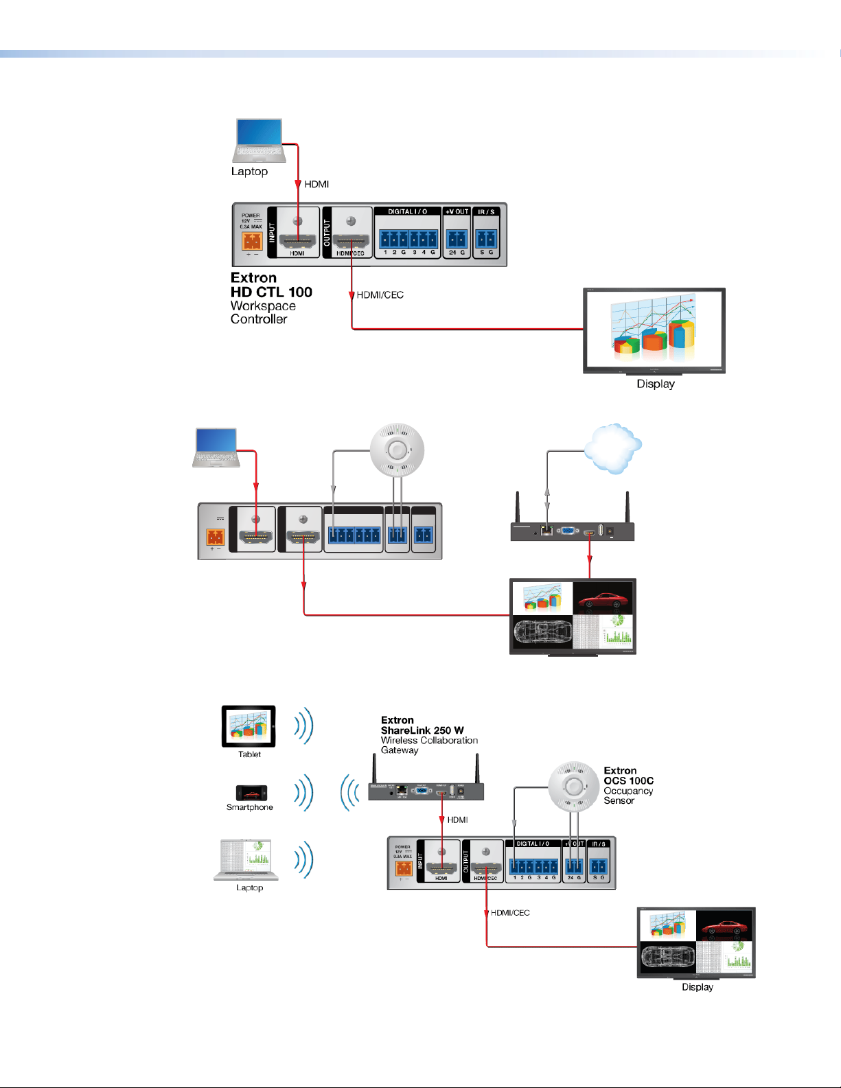
Application Diagrams
n
Display
La
Figure 1. HD CTL 100 Application Example 1
ptop
Extron
OCS 100C
Occupancy
Sensor
TCP/IP
Network
HDMI
Ethernet
+V OUTDIGITAL I / O
POWER
12V
0.3A MAX
INPUT
Extron
HD CTL 100
OUTPUT
HDMI/CECHDMI
21G 43G
HDMI
IR / S
SG
G 24
ShareLink 250 W
MODEL 80
VGA OUT HDMI OUT
AUDIO
OUT
LAN / PoE
USB 3
2.3A MAX
HDMI
POWER
Extron
5V
ShareLink 250 W
Wireless Collaboratio
Gateway
HDMI Controller
FLAT PANEL
Figure 2. HD CTL 100 Application Example 2
Extron
HD CTL 100
Workspace
Controller
Figure 3. HD CTL 100 Application Example 3
HD CTL 100 Controller • Introduction 3
Page 12
Installation and Operation
This section describes the front and rear panel features of the HD CTL 100, and provides
procedures for installing and operating it. Topics include:
• Installation Overview
• Rear Panel Features
• Connecting Power to the HD CTL 100
• Front Panel Features
• Resetting
Installation Overview
ATTENTION:
• Installation and service must be performed by authorized personnel only.
• L’installation et l’entretien doivent être effectués uniquement par un électricien
qualifié.
• All electrical installation should be performed by qualified personnel in accordance
with local and national building codes, fire and safety codes, and local and
national electrical codes.
• Toute installation électrique devrait être effectuée par un personnel qualifié,
conformément aux codes du bâtiment, aux codes incendie et sécurité, et aux
codes électriques locaux et nationaux.
1. Mount the HD CTL 100 on a wall, rack, rack shelf, or furniture. Mounting kits and
instructions are available at www.extron.com.
TIP: Extron recommends wall-mounting the HD CTL 100 behind the display
(place the top panel of the unit against the wall), using a mounting kit such
as the Extron MBU 125 Under Desk Mounting Brackets (see figure35 on
page38).
2. Attach the cables to the rear panel connectors of the HD CTL 100 and to the display
device (see Rear Panel Features, beginning on page 5). Attach an optional IR
emitter if used.
3. Wire and connect the HD CTL 100 power supply (see Connecting Power to the
HD CTL 100 on page 10).
4. Connect all other power cords and power on all the devices, including the
HD CTL 100.
5. Download and install the HD CTL 100 Configuration Program (see Downloading
and Installing the Configuration Program on page 14).
HD CTL 100 Controller • Installation and Operation 4
Page 13
6. Download drivers for the devices you are connecting to the HD CTL 100 (see
AAA
BBB
CCC
DDD
EEE FFF
Obtaining Device Drivers on page 19 or the configuration program help file).
7. Connect a USB A-to-USB mini-B cable to the front panel HD CTL 100 USB CONFIG
port and to a USB port on your computer.
8. Configure the HD CTL 100 ports using the configuration program (see the
HD CTL 100 Configuration Program Help file for these procedures). To access
the help file, see Downloading and Installing the Configuration Program on
page 14.
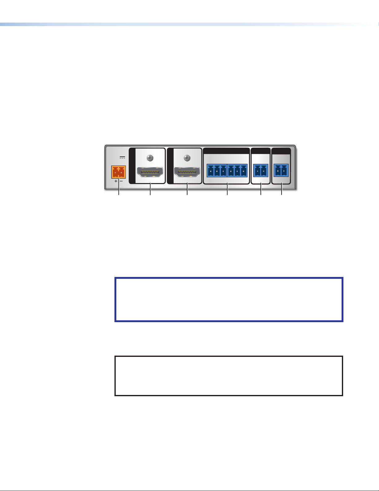
Rear Panel Features
The HD CTL 100 rear panel contains the following connectors:
POWER
12V
0.3A MAX
INPUT
Power connector
A
HDMI input connector
B
HDMI/CEC output connector F IR/S control connector
C
Figure 4. HD CTL 100 Rear Panel
Power connector — Connect the provided 12 VDC, 0.5 A power supply (or any
A
other power supply capable of providing 12 VDC, 0.5 A of power) to this 2-pole
captive screw connector.
ATTENTION:
• Do not connect power to the unit until you have read the CAUTION AND
ATTENTION notices on page 10.
• Ne branchez pas l’alimentation au l’unité avant d’avoir lu les mises en garde
ATTENTION de la page 10.
OUTPUT
HDMI/CECHDMI
21G 43G
Digital I/O connector
D
Voltage output connector
E
+V OUTDIGITAL I / O
IR / S
SG
G 24
HDMI input connector — Connect an HDMI source to this female HDMI connector.
B
Resolutions up to 4K (4096 x 2016 @ 60 Hz) are supported. The HD CTL 100
supports an input cable of up to 12 feet (3.6 meters).
NOTE: LockIt cable lacing brackets are provided with the HD CTL 100 unit.
These brackets secure the HDMI cables to the rear panel input and output HDMI
connectors and reduce stress on the connectors, preventing signal loss due to
loose cable connections. To install these brackets, see Installing the LockIt
HDMI Cable Lacing Brackets on page 9.
HD CTL 100 Controller • Installation and Operation 5
Page 14
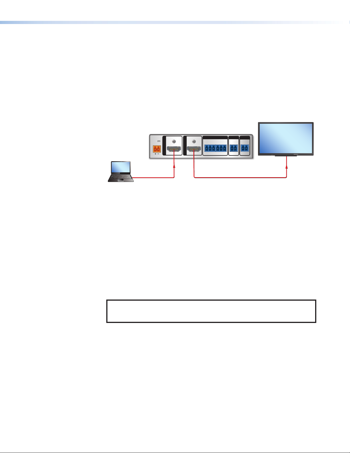
HDMI/CEC output connector — Connect an HDMI display to this female HDMI
Laptop
y
C
pass-through port to enable the controller to turn the display on when HD CTL
100 detects an input signal and off when the signal is no longer detected. The
HD CTL 100 supports an output cable of up to 12 feet (3.6 meters).
Through this port, the HD CTL 100 can send pre-loaded CEC commands to the
connected HDMI output device (see CEC Control on page 24). CEC commands
are issued from the HDMI output port and configured using the HD CTL 100
Configuration Program (see Downloading and Installing the Configuration
Program on page 14 to obtain the configuration software, and the program help file
to enable the CEC commands). See figure5 for an example of wiring the HDMI ports
to enable CEC control.
MODEL 80
HD CTL 100
+V OUTDIGITAL I / O
POWER
12V
0.3A MAX
INPUT
HDMI signal detected on
the HDMI Input port
.
HDMI
OUTPUT
HDMI/CECHDMI
21G 43G
CEC command turns on display.
IR / S
SG
G 24
HDMI/CEC
FLAT PANEL
Displa
Figure 5. Wiring for CEC Control
Digital I/O connector — This 6-pole captive screw connector provides four digital
D
input or output ports (plus two ground pins) to which you can connect sensors,
switches, or contact closure buttons. Each port can be configured as a digital input,
output, input with pull-up, or output with pull-up, via the HD CTL 100 configuration
software. The ports enable you to monitor connected devices and trigger functions
on the controller (see Connecting Devices to the Digital I/O Ports on page 8 for
instructions on wiring devices to these ports).
Voltage Output (+V Out) connector — This +24 V (voltage and ground) captive
E
screw power output can provide power to connected accessories that require +24 V
of power, such as occupancy sensors.
IR/S control connector — This port provides unidirectional communication to
F
control a projector or a display via RS-232 or IR. The S (signal) and G (ground) pins of
the 2-pole captive screw IR/S connector comprise the IR/serial port.
NOTE: The HD CTL 100 can be configured to send CEC, unidirectional RS-232,
and IR commands, using the HD CTL 100 Configuration program (see the
HD CTL 100 Configuration Program Help file for more information).
HD CTL 100 Controller • Installation and Operation 6
Page 15
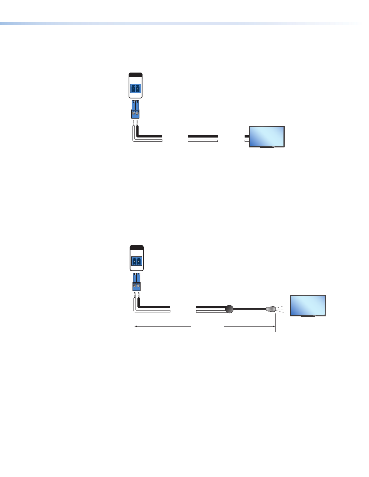
• For RS-232 control — Connect the S and G pins of the IR/S connector to the
HD CTL 100
HD CTL 100
RS-232 port of a display device or switcher (see figure6).
IR/S Port
IR / S
SG
Display
MODEL 80
Ground (G)
Transmit (Tx)
Ground (G)
Receive (Rx)
FLAT PANEL
Figure 6. Connecting a Display to the IR/S Port
• For IR control — Connect the S and G pins of the IR/S connector to an IR
emitter, with a maximum of 50 feet (15 m) distance from port to emitter.
To control devices via infrared (IR) commands from the HD CTL 100, connect
an IR emitter to the S (signal) and G (ground) pins of the connector. The IR port
provides unidirectional IR signal output to control a display, projector, switcher, or
other device such as a Blu-ray player.
Example: Figure 7 shows a single IR emitter connected to the IR/S port of an
HD CTL 100.
IR/S Port
IR / S
SG
Display
MODEL 80
Ground (G)
IR Signal (S)
50'
(15 m max)
IR Emitter
FLAT PANEL
Figure 7. Connecting a Display to the IR/S Port
See the communication sheets for your device drivers for information on compatible baud
rates and cabling type and distance. These communication sheets are accessed via the
HD CTL 100 configuration program and also from the Download tab at www.extron.com
(see Obtaining Device Drivers on page 19 or the configuration program help file to view
the communication sheets and download the device drivers).
HD CTL 100 Controller • Installation and Operation 7
Page 16

Connecting Devices to the Digital I/O Ports
I
/CEC
1
Device 1
The Digital I/O ports on the HD CTL 100 rear panel let you connect a switch or sensor to
control other devices in the room that are connected to the HD CTL 100 IR/S control port.
The Digital I/O ports measure two states — high and low — of the connection between
the switch or sensor and the connected device. The port accepts 0 to 24 VDC input. The
threshold voltages are as follows:
• Voltage below 1.0 VDC is measured as logic low.
• Voltage above 1.5 VDC is measured as logic high.
There is also an internal, +5 VDC, selectable, pull-up resistor for this circuit. If a connected
device does not have its own power source and be powered through the controller,
select (via the HD CTL 100 configuration software) Input with Pullup for this port (see
the HD CTL 100 Configuration Program Help file to enable input with pullup).
In addition, you can program actions on this port, so that each time a high or low state is
detected, one or more functions are performed (see the configuration software help file to
configure the Digital I/O ports).
To wire the Digital I/O connector:
1. Connect a digital input or output device (such as a switch, relay device, or sensor) to
pin 1, 2, 3, or 4 and to one of the two G (ground) pins of the Digital I/O connector.
NOTE: Use the two 3-pole captive screw plugs provided with the HD CTL 100 to
connect devices to the 6-pole Digital I/O connector (no 6-pole plug is provided).
2. (Optional) If using an occupancy sensor or other device that requires +24 V
+V OUT
power and does not have a power supply, wire its power connector to the
rear panel HD CTL 100 +V OUT connector (see figure4, E, on page5,
and the illustration at right).
G 24
NOTE: The maximum current for this connector is 50 mA.
HD CTL 100
Rear Panel
21G 43G
+V OUTDIGITAL I / O
Heat
Shrink
Over
Shield
Wires
IR/S
SG
G24
G
2
1
G
2
1
Switch,
Sensor
Digital I/O (digital input/output)
Congure each port as a digital input or output,
with or without +5 VDC pull-up. Use these
ports to:
• Monitor or trigger events and functions (toggle
relays, issue commands, send e-mail), once
congured.
• Power LEDs or other devices that accept a
TTL signal.
Share the same
ground among I/O
Wire
connections.
Nut
Device 4
Device 3
(Switches, sensors,
LEDs, relays, or
Device 2
similar items)
Figure 8. Wiring the Digital I/O Connectors (Example)
HD CTL 100 Controller • Installation and Operation 8
Page 17

• Digital input — Use one or more of the Digital I/O ports to connect a sensor, such
1
as an occupancy sensor, or a switch, such as a push-button device that can be
configured to be triggered by a press or release of the button.
• Digital output — Use one or more of the Digital I/O ports as a digital output to
control LEDs, incandescent lights, or other devices that accept a transistor-totransistor logic (TTL) signal. They can also provide contact closure control for
projector lifts, motorized screens, or room and light switches when attached to relay
devices. Each port can sync up to 250 mA.
NOTES:
• If the digital output port is set with pull-up disabled, the voltage output is set
by an external source.
• If the pull-up resistor is enabled, the voltage output is equal to approximately
+4.6 V.
Installing the LockIt HDMI Cable Lacing Brackets
The Extron LockIt lacing brackets make it possible to
simply and universally secure a standard HDMI cable
to most HDMI devices.
NOTE: The HDMI device must have an HDMI
connection mounting screw for this bracket to
be used.
2
To securely fasten an HDMI cable to a device:
3
1. Plug the HDMI cable into the panel connection.
2. Loosen the HDMI connection mounting screw from
the panel enough to allow the LockIt lacing bracket
to be placed over it. The screw does not have to be
removed.
3. Place the LockIt lacing bracket on the screw and
against the HDMI connector, then tighten the screw
to secure the bracket.
4
3
4. Loosely place the included tie wrap around the HDMI connector and the LockIt lacing
bracket as shown.
5. While holding the connector securely against the lacing bracket, tighten the tie wrap,
then remove any excess length.
ATTENTION:
• Do not overtighten the HDMI connection mounting screw. The shield to
which it is fastened is very thin and can easily be stripped.
• Ne serrez pas trop la vis de montage du connecteur HDMI. Le blindage
auquel elle est attachée est très fin et peut facilement être dénudé.
HD CTL 100 Controller • Installation and Operation 9
Page 18

Connecting Power to the HD CTL 100
CAUTION: Risk of electric shock. The wires must be kept separate while the
power supply is plugged in. Remove power before wiring.
ATTENTION : Risque de choc électrique. Les deux cordons d’alimentation
doivent être tenus à l’écart l’un de l’autre quand l’alimentation est branchée. Couper
l’alimentation avant de faire l’installation électrique.
ATTENTION:
• The power supply must not be permanently fixed to the building structure or
similar structures.
• La source d’alimentation ne devra pas être fixée de façon permanente à une
structure de bâtiment ou à une structure similaire.
• Do not place the power supply within environmental air handling spaces or the
wall cavity.
• Ne pas placer les sources d’alimentation dans une zone de traitement de l’air ni
dans une cavité murale.
• The installation must be in accordance with the applicable provisions of the
National Electrical Code ANSI/NFPA 70, Article 725 and the Canadian Electrical
Code, Part 1, Section 16.
• Cette installation doit toujours être en accord avec les mesures qui s’applique
au National Electrical Code ANSI/NFPA70, article725, et au Canadian Electrical
Code, partie1, section16.
• Use a UL Listed external power supply with rated output 12 VDC, minimum
0.5 A, NEC Class 2, or LPS output.
• Utilisez une source d’alimentation externe certifiée UL, avec une tension nominale
12 Vcc, 0,5 A minmum, NEC Class 2, ou sortie LPS.
• The power supply must be located within the same vicinity as the Extron AV
processing equipment in an ordinary location, Pollution Degree 2, secured to a
podium, a desk, or an equipment rack within a dedicated closet.
• La source d’alimentation doit être située à proximité de l’équipement audiovisuel
Extron dans un emplacement habituel, avec un degré de pollution 2, fixée à une
estrade, un bureau, ou dans une baie technique à l’intérieur d’un placard dédié.
• Always use a power supply specified by Extron for the HD CTL 100. Use of an
unauthorized power supply voids all regulatory compliance certification and may
cause damage to the supply and the HD CTL 100.
• Utilisez toujours une source d’alimentation fournie ou recommandée par Extron.
L’utilisation d’une source d’alimentation non autorisée annule toute conformité
réglementaire et peut endommager la source d’alimentation ainsi que le produit
final.
HD CTL 100 Controller • Installation and Operation 10
Page 19

Connect the provided 12 VDC, 0.5 A power supply to the HD CTL 100 as follows:
AA
(0.5 A, 12 VDC)
1. Wire one of the supplied orange 2-pole captive screw connectors as shown below.
Smooth
Power Supply Output Cord
Ridges
SECTION A–A
3/16” (5 mm) Max.
Figure 9. Wiring the Power Connector
ATTENTION:
• Installation and service must be performed by authorized personnel only. UL
listed junction boxes are recommended.
• L’installation et l’entretien doivent être effectués par le personnel autorisé
uniquement. Des boîtiers électriques approuvés UL sont recommandés.
• The length of the exposed wires in the stripping process is critical. The ideal
length is 3/16 inches (5 mm). If they are any longer, the exposed wires may
touch, causing a short circuit between them. If they are any shorter, the wires
can be easily pulled out even if tightly fastened by the captive screws.
• La longueur des câbles exposés est primordiale lorsque l’on entreprend de
les dénuder. La longueur idéale est de 5mm (3/16inches). S’ils sont un peu
plus longs, les câbles exposés pourraient se toucher et provoquer un court
circuit. S’ils sont un peu plus courts, ils pourraient sortir, même s’ils sont
attachés par les vis captives.
2. Plug the connector into the orange 2-pole captive screw power connector on the rear
panel. In the example shown in figure10, a power supply is being connected to the
power connector of an HD CTL 100.
12 VDC Input
Ground
External
Power Supply
Ground all devices.
POWER
12V
0.3A MAX
INPUT
HDMI
Figure 10. Connecting a Power Supply to an HD CTL 100
HD CTL 100 Controller • Installation and Operation 11
Page 20

Front Panel Features
The HD CTL 100 front panel contains the following items:
BBB CCC DDD
R
AAA
Power LED
A
Reset button
B
USB configuration port
C
Signal and Reset LED
D
Figure 11. HD CTL 100 Front Panel
Power LED — This green LED lights steadily when the unit receives +12 V of power
A
from an external power supply (provided).
Reset button — Using the provided Extron Tweeker or other small screwdriver, press
B
this recessed button to initiate a reset to factory firmware or a configuration reset (see
Resetting on the next page).
USB configuration port — Connect a USB A-to-USB mini-B cable between the
C
computer and this port to configure the HD CTL 100 via the configuration software
and to update the firmware.
Signal and Reset LED — This green LED lights when an active HDMI source is
D
connected to the rear panel HDMI input port.
When a reset is initiated, this LED also blinks to indicate the progress of the reset (see
Resetting on the next page).
SIGNAL
CONFIG
HD CTL 100
HD CTL 100 Controller • Installation and Operation 12
Page 21

Resetting
If it becomes necessary to reset the HD CTL 100 to its default factory firmware or to
the default configuration settings that were implemented at the factory, you can use
the Reset button, SIS commands (see the Reset command on page 27) or the
configuration program (see the HD CTL 100 Configuration Program Help file).
111 22
R
SIGNAL
CONFIG
Figure 12. Reset Button and Signal LED
Two types of reset are available:
• Resetting to the default configuration
1. While the HD CTL 100 is powered on, press and hold the Reset button (see
figure12, 1).
2. After 3 seconds, the Signal LED (2) blinks once. Release the button, then
immediately (within 1 second) press it again and release it immediately
(momentary press).
When the reset is finished, the Signal LED blinks three times, indicating that the
reset was successful.
• Resetting to the factory firmware version
NOTE: This procedure does not reset the configuration on the device.
1. With the HD CTL 100 powered off, press and hold the Reset button.
2. Continue to hold the button while applying power to the HD CTL 100.
3. When the reset is complete, the Signal/Reset LED blinks three times, then, if a
source is connected, remains lit steadily. Release the Reset button.
You can also reset the unit to factory defaults using the HD CTL 100 Configuration
Program (see the program help file for instructions).
HD CTL 100 Controller • Installation and Operation 13
Page 22

Remote Configuration and Control
HD CTL 100 can be remotely configured via a host computer that is attached to the front
panel USB port using the HD CTL 100 Configuration Program. This section describes
procedures for obtaining and accessing the configuration software, as well as providing a
list of the available SIS commands and the procedures for issuing them.
The following topics are covered:
• HD CTL 100 Configuration Program
• SIS Commands
HD CTL 100 Configuration Program
An HD CTL 100 controller must be configured in order for it to be able to control other
devices. The Extron HD CTL 100 Configuration Program enables you to set up the
HD CTL 100 rear panel ports and to update firmware. Using this program, you can create
configurations on your computer for your HD CTL 100 and then upload them to the controller
via the front panel USB port. (The HD CTL 100 does not have to be connected to the
computer while you are creating the configurations, only while uploading them.)
See Installation and Operation starting on page4, for explanations of the
configuration ports. See the configuration program help file to create and upload the
configurations.
Downloading and Installing the Configuration Program
The HD CTL 100 Configuration Program can be downloaded free of charge from the
Extron website. To obtain the configuration program, download it to your computer as
follows:
1. On the Extron website, hover the mouse pointer over the Download tab (see
figure13, 1, on the next page), then move the pointer to the Software link (2) in
the Downloads column and click it.
HD CTL 100 Controller • Remote Configuration and Control 14
Page 23

Figure 13. Software Link on the Download Page
2. On the Download Center screen, click the H link (see figure14, 1).
Figure 14. H Link on Download Center Page
3. Scroll to locate the HD CTL 100 Configuration Program on the list of available
software programs and click the Download link to the far right of the name.
4. On the login page that appears next, fill in the required information to log into
the www.extron.com website (if you need an ID number, see your Extron
representative).
HD CTL 100 Controller • Remote Configuration and Control 15
Page 24

5. Follow the instructions on the subsequent screens to complete the software program
installation. By default, the configuration program files are stored on your computer at:
C:\Program Files (x86)\Extron\HDCTL_100
If there is not already an Extron folder in your Program Files x86 folder, the
installation program creates it as well.
Starting the Configuration Program
To use the HD CTL 100 to control devices, you must create one or more configurations for
it, using the HD CTL 100 Configuration Program. A configuration is a set of specifications
for command assignments and port parameters that enable the HD CTL 100 to control
your display device.
NOTES:
• Configurations can be created away from the job site and without the
HD CTL 100 being connected to the computer.
• Uploading Configuration Time: The HD CTL 100 requires approximately one
minute to write the configuration to memory after the software indicates the
process is complete. The completion is indicated with multiple flashes from the
power LED on the front panel.
• Command Ordered List: When configuring commands within the software,
commands in the Selected Actions play/execute from the top of the list to the
bottom.
After you have downloaded and installed the program (see Downloading and Installing
the Configuration Program on page 14) and device drivers if necessary (see Obtaining
Device Drivers on page 19), begin by creating a new project.
An HD CTL 100 project is a file (with a .mli extension) that contains port configurations
for an HD CTL 100. A configuration must be created within a new or existing project.
A project can be saved, copied, and edited (for example, by adding or changing
configurations within it). You can also create a configuration and add it to an existing
project. You can start a new project either when first opening the HD CTL 100 program or
while the program is open and another project is active.
To start the configuration program:
1. Open the HD CTL 100 Configuration Program by selecting HD CTL 100 from the
computer Start menu. Click:
All Programs\Extron Electronics\HD CTL 100\HD CTL 100.
The Start Options dialog box opens in front of the HD CTL 100 Configuration
Software window.
2. On the Start Options dialog box, select the Create a New Project radio button
(see figure15, 1, on the next page).
HD CTL 100 Controller • Remote Configuration and Control 16
Page 25

Figure 15. Start Options Dialog Box
3. If desired, click the Add Driver Subscriptions button (2) to add drivers to the
HD CTL 100 (see Obtaining Device Drivers). You can also add drivers via the
software at any time.
4. Click OK. The HD CTL 100 Configuration Software main window opens, with Unnamed
Project displayed in the title bar (see figure16, 1).
Figure 16. The HD CTL 100 Main Window
The following is displayed on the HD CTL 100 main window:
• Title bar — In the title bar, the project name is displayed (the asterisk following
the name indicates that the project has not been saved since changes were
made).
HD CTL 100 Controller • Remote Configuration and Control 17
Page 26

• Configuration tabs — Four tabs provide access to screens containing controls
that you use to configure the HD CTL 100 (see the configuration program help file
for explanations of their contents). From these screens you can:
• Digital I/Os (Digital I/O Configuration screen) — Configure the
operation of the four Digital I/O ports and select the operating modes of the
devices connected to these ports.
• Monitors (Monitor Configuration screen) — Monitor port and signal
status, and set up conditions that trigger selected actions to be performed by
devices connected to the ports.
• Ports (Port Configuration screen) — Configure the IR/S port, to which
your display device will be connected, and select drivers for the device.
• Advanced (Advanced Configuration screen) — Select power timeout,
warm-up, and cool down settings.
• Menu bar — The menu bar contains four drop-down menus from which you can
select options to manage new and saved projects, obtain device drivers, upload
firmware, display this help file, and more. Many of the functions accessed from
these menu options also are available as buttons on the toolbar.
When you place the mouse pointer over a button on the toolbar, the function
of the button is displayed as pop-up text, called a tooltip (see the example in
figure 17).
• Toolbar — Located below the menu bar on the main window the toolbar
contains buttons that enable you to manage HD CTL 100 projects and device
configurations, upload firmware, and access the HD CTL 100 Configuration
Program Help. Many of the functions accessed by these buttons also are
available as options on the menus.
When you place the mouse pointer over a button on the toolbar, a tooltip pops
up, explaining the button function (see the example in figure17).
5. Save and name a project as follows:
a. From the File menu, select Save As... .
b. In the Save As dialog box, give your project file a name and save it to the desired
location on your computer.
NOTE: Your project is saved as a file with the extension .hdc.
You are now ready to create configurations for your HD CTL 100 device by specifying
parameters for its ports (see the configuration program help file for procedures).
Accessing the help file
For instructions on creating configurations using the program, see the HD CTL 100
Configuration Program Help file. You can access the help file when the configuration
program is open using any of the following methods:
• From the Help menu, select HD CTL 100 Configuration Program Help.
Figure 17. Configuration Program Help Menu
HD CTL 100 Controller • Remote Configuration and Control 18
Page 27

• Click the Help icon on the main window toolbar (see figure18, 1). (When you hover
the mouse pointer over a toolbar icon, a pop-up explanation of its function appears
(see figure 18).
Figure 18. Help Icon on Configuration Program Toolbar
• Press the <F1> key on your computer keyboard.
Obtaining Device Drivers
The Extron drivers are control files (libraries) of commands created by Extron that are
specific to a particular display device or switcher. There are different sets of drivers for
serial (RS-232) and IR control. Before you can use the configuration program to configure
the HD CTL 100 ports, the necessary drivers must be loaded onto your computer. You
must then select the driver appropriate to the HD CTL 100 for your device in order to
configure it to control the device. Serial and IR drivers are available at no charge from
www.extron.com. You can download them directly from the web or through the
configuration program.
NOTES: By default the downloaded drivers are stored in the Driver2 folder on your
computer, located at c:\Users\Public\Documents\Extron\Driver2
Downloading drivers using the configuration program
The easiest way to obtain the drivers for your devices is via the HD CTL 100 configuration
program. You can initiate this process by two methods:
• Click the Add Driver Subscriptions button on the Start Options dialog box
(described below).
• Select Driver Subscriptions from the Edit menu on the main window (you can
do this at any time while the program is open, regardless of whether a project has
been created).
NOTE: Your computer must have an active internet connection to download drivers.
1. Click Start\All Programs\Extron Electronics\HD CTL 100\HD CTL 100
or double-click the HD CTL 100 software icon (shown at right), which is
placed on your desktop during software installation, to launch the
HD CTL 100 Configuration Program application. The HD CTL 100
Configuration Program main window opens, with the Start Options dialog box
displayed in front of it.
2. On the Start Options dialog box, click the Add Driver Subscriptions button
(see figure19, 1, on the next page).
HD CTL 100 Controller • Remote Configuration and Control 19
Page 28

Figure 19. Start Options Dialog Box
3. In the Available Drivers Subscription panel of the Driver Subscriptions
dialog box, select the device types for which you want to download drivers (see
figure20).
Figure 20. Driver Subscription Dialog Box
HD CTL 100 Controller • Remote Configuration and Control 20
Page 29

• To select all device types available from a manufacturer, select the checkbox
in front of the manufacturer name. Each manufacturer whose drivers you select is
listed in the Current Drivers Selection column.
• To select individual device types from a manufacturer, click the plus (+) sign
in front of the manufacturer name to expand it and display all the device types of
that manufacturer for which drivers are available, then select the desired device
check boxes. To hide the devices, click the minus (–) sign.
• To expand or collapse the list of manufacturers and view or
hide all their drivers, click the Expand all or Collapse all
buttons (shown at right) at the top of either column.
NOTE: When you select a device, both the IR and serial drivers for it are
downloaded.
4. Make any desired optional selections:
• Select the Auto-check for new subscribed drivers checkbox if you want
the HD CTL 100 to continually check for and download any updates to your
subscribed drivers. When a new version of any of your subscribed drivers is
available on the Extron website, that new version is automatically downloaded
when the configuration program is started.
• Click Set Proxy if you want to download your drivers using proxy server settings
(see the configuration program help file for more information).
If you want to close the dialog box without downloading any drivers, click Close to
save any changes you have made on this dialog box or Cancel if you want to discard
your changes.
5. Click Download. The Driver Subscriptions Download dialog box opens,
displaying all drivers that have been selected or previously downloaded to your
computer (see figure21).
Figure 21. Driver Subscriptions Download Screen
• If a driver on the list is new for your computer, it has the designation Waiting...
in the Status column (1).
• If a driver already exists on your computer, its designation is Already in Driver
Catalog.
HD CTL 100 Controller • Remote Configuration and Control 21
Page 30

6. In the Driver Subscriptions Download dialog box, click Begin (2) to download
the drivers listed in the Driver File panel. While the download is in progress:
• The Elapsed Time panel (see figure22, 1, on the next page) shows the amount
of time that has passed since the download process started.
• The Progress Bar (2) indicates the progress of the download.
• As each new driver is downloaded, its designation in the Status column changes
to Completed (3).
7. When the Progress Bar (see figure 22, 2) and the Status column (3) indicate that
the download has completed, click Close (4) to close the Driver Subscriptions
Download dialog box.
Figure 22. Driver Subscriptions Download Screen after a Driver Download
HD CTL 100 Controller • Remote Configuration and Control 22
Page 31

Downloading drivers from the Web
Drivers can also be obtained directly from the Extron website without using the control
program as follows:
1. Go to www.extron.com, and mouse over the Download tab (see figure23, 1) at
the top of the page.
2. On the Download screen, click the Control System Drivers link (2) on the left
sidebar.
Figure 23. Control System Drivers Links on the Download Screen
The Control System Drivers page opens (see figure24 on the next page).
3. From the Extron Product menu (1) on the Control System Drivers screen,
select HD CTL 100 if it is not already selected. The other menus become available.
HD CTL 100 Controller • Remote Configuration and Control 23
Page 32

Figure 24. Selecting HD CTL 100 from the Device Drivers Drop-down Menu
4. From the rest of the menus on the screen, select search criteria for the drivers you
want to download:
• From the Protocol Type menu (2), select IR, Serial, or All.
• From the Manufacturer menu (3), select the manufacturer of the device for
which you are downloading the drivers, or All to select all device manufacturers.
• From the Product Category menu (4), select the type of device (for example,
video projector) or All.
• From the Model menu (5), select the device model name or number, or All.
As you make each selection, the driver list below changes to display all available
drivers meeting your selected criteria.
HD CTL 100 Controller • Remote Configuration and Control 24
Page 33

5. Click on the device name whose driver you want to download.
To download all the drivers in the current package, click the Download install for
current driver package (Login required) link (see figure25, 1).
Figure 25. Download Install for Current Driver Package Link
NOTE: The website may contain additional drivers that became available after the
current driver package was created. These new drivers may be on the website,
but have not been incorporated into the driver package.
If you want to ensure that you are getting all the drivers currently available, use
the configuration program to download the drivers (see Downloading drivers
using the configuration program on page 19).
6. On the next screen, enter the requested information. If you need an ID number
(password), contact your Extron representative.
7. Follow the directions on the download screens that follow. Unless you specify
otherwise, the driver file is placed at:
c:\Users\Public\Documents\Extron\Driver2
CEC Control
CEC can control standard functions on a display attached to the HDMI output by inserting
unidirectional CEC control commands. These commands are available to be issued via
the HD CTL 100 Configuration Program (see the program help file for instructions on using
the commands).
The following CEC commands are included in the HD CTL 100 firmware:
• Power on • Volume up
• Power off • Volume down
• Input selection • Audio mute (toggle on and off)
Using the configuration program, you can configure CEC commands to be sent to the
output device when:
• A digital input is triggered.
• Signal presence is detected or not detected.
• An action detected by a monitor (also set up via the configuration program) is
triggered.
You can also insert user-defined CEC commands to be issued to the display (see the
HD CTL 100 Configuration Program Help file for the procedure).
HD CTL 100 Controller • Remote Configuration and Control 25
Page 34

SIS Commands
Host-to-Controller Communications
Default functionality
The HD CTL 100 is preconfigured with the following monitors and actions, which can be
reconfigured via the HD CTL 100 Configuration Program (see the program help file).
• When a stable HDMI (TMDS) signal is detected, the HD CTL 100 sends the CEC
Power On command to the connected sink (display).
• When no HDMI (TMDS) signal is present for 30 seconds, a CEC Power Off
command is sent to the connected sink.
You can reconfigure these monitors and actions using the HD CTL 100 Configuration
Program (see the program help file).
You can issue SIS commands to the HD CTL 100 via the USB interface of your computer
or control device with a communication software program such as Extron DataViewer.
SIS commands consist of strings of one or more characters per field. No special
characters are required to begin or end a command sequence. When the HD CTL 100
determines that a command is valid, it executes the command and sends a response to
the host device.
Most responses from the HD CTL 100 to the host end with a carriage return and a line
feed (CR/LF = ]), which signals the end of the response character string.
Controller-initiated Messages
When a local event takes place, the HD CTL 100 responds by sending a message to the
host, indicating what selection was entered. No response is required from the host.
Error Responses
If the HD CTL 100 is unable to execute a command it receives because the command is
invalid or contains invalid parameters, the controller returns an error response to the host.
This response consists of the letter E followed by a number and a carriage return with a
line feed. The following error response codes can be returned:
E10 – Invalid command or parameter
E13 – Invalid value (out of range)
Using the Command and Response Table
The Command and Response Table for SIS Commands on page 27 lists valid ASCII
command codes, the responses of the HD CTL 100 to the host, and a description of
the command function or the results of executing the command. The ASCII to Hex
Conversion Table on the next page is for use with the Command and Response Table.
HD CTL 100 Controller • Remote Configuration and Control 26
Page 35

ASCII to HEX Conversion Ta ble
Space
NOTE: For commands and examples of computer or device responses used in this
guide, the character "0" is the number zero and "O" is the capital letter "o".
Symbol Definitions
]
= CR/LF (carriage return with line feed) (hex 0D 0A)
}
or | = Soft carriage return (no line feed) (hex 0D)
• = Space
E
or W = Escape key (hex 1B)
NOTE: Unless otherwise indicated, commands are not case-sensitive.
•
X!
= Input signal status
0 = No input signal detected
1 = Input signal detected
X@
= Unit name — Text string of up to 24 alphanumeric characters and the hyphen (–).
• Spaces are not permitted.
• First character must be a letter.
• Last character cannot be a hyphen.
X#
= Firmware version number (displayed to two decimal places: n.nn)
X$
= +5 V output mode
0 = Auto: +5 V is enabled only when a source with +5 V is present
1 = +5 V is always enabled (default)
X%
= Verbose mode
0 = Clear/none
1 = Verbose mode (default)
2 = Tagged response for queries
3 = Verbose mode and tagged response for queries
HD CTL 100 Controller • Remote Configuration and Control 27
Page 36

Command and Response Table for SIS Commands
Command
ASCII Command
(Host to Unit)
Response
(Unit to Host)
Additional Description
Signal Status
Request input signal status
ELS}
Verbose mode 2 and 3
]
1*X!
Sig1*X!
View input 1 signal presence X!.
]
Device Name
Set unit name
Set unit name to factory
default
View unit name
E X@
E
E
Verbose mode 2 and 3
CN
• CN
CN
}
}
}
Ipn•X@
Ipn•HD-CTL-100
]
X@ ]
Ipn•X@
]
]
Set the name of the HD CTL 100
to X@.
Reset the unit name to its factory
default name: HD-CTL-100.
Show the name (X@) of the
HD CTL 100.
Information Requests
Query firmware version
Query part number
Q
Verbose mode 2 and 3
N
Verbose mode 2 and 3
X# ]
X#]
Ver01*
60-1633-01
Pno60-1633-01
]
]
Display firmware version X# to
two decimal places.
Show the part number of the
unit.
+5 V Output Mode
Set +5 V output mode
View +5 V output mode status
E
M X$ HPLG
E
MHPLG
Verbose mode 2 and 3
}
}
HplgM X$
X$ ]
X$]
HplgM
]
Select +5 V output mode
View current +5 V output mode
Verbose Mode
Set verbose mode
View verbose mode
E X%
E
Verbose mode 2 and 3
CV
CV
}
}
VrbX%
X% ]
X%]
Vrb
]
Reset
Reset to defaults
KEY:
X!
= Input 1 signal status
0 = No input signal detected
1 = Input 1 signal detected.
X@
= Unit name: Text string of up to 24 alphanumeric characters and the hyphen (–).
• Spaces are not permitted.
• First character must be a letter.
• Last character cannot be a hyphen.
X#
= Firmware version (displayed to two decimal places)
X$
= +5 V output mode
0 = Auto: +5 V is enabled only when a source with +5 V is present
1 = +5 V is always enabled (default).
X%
= Verbose mode
E
ZXXX
}
Zpx
]
Reset the HD CTL 100 to the
factory defaults.
0 = Clear/none
1 = Verbose mode (default)
2 = Tagged response for queries
3 = Verbose mode and tagged response for queries
HD CTL 100 Controller • Remote Configuration and Control 28
Page 37

Application Example
This section describes an example of a typical HD CTL 100 power control application that
includes a variety of devices. The system illustrated in figure26, below, and figure27, on
the next page, is designed to control the display power by three different methods: input
signal detection, contact closure, and occupancy sensor.
5
OCS 100
3
Q4 Sales by Region
Southwest
Southeast
Northeast
HD CTL 100
+V OUTDIGITAL I / O
HDMI
IR / S
S G
G 24
POWER
12V
0.3A MAX
4
INPUT
OUTPUT
HDMI/CECHDMI
21 G 43 G
Extron
AVEdge 100
IR / S
+V OUT
SG
G 24
DIGITAL I / O
43 G
21 G
OUTPUT
HDMI/CEC
HDMI
INPUT
POWER
12V
0.3A MAX
Northwest
Central
ON/OFF
TOGGLE
125V 50-60Hz 12A MAX
USB CHARGER
Edge Mount Enclosure
for Display Power with
CCR 2BLB Control,
AV Connectivity
and Data.
2
ON/Off
TOGGLE
125V 50-60Hz 12A MAX
USB CHARGER
11
Q4 Sales by Region
Southwest
Northwest
Northeast
Central
Southeast
Figure 26. Application Example
HD CTL 100 Controller • Application Example 29
Page 38

This section contains instructions for using the configuration software to set up the power
CCR 2BLB
Extron
To Display
From AVEdge
2
3
control in the following three ways:
• Detection of the input source signal (see Input Signal Detection on page31)
• A two-button contact closure device (an Extron CCR 2BLB, see Contact Closure
Device on page33)
• Detection of room occupancy by an occupancy sensor (such as an Extron OCS 100,
see Occupancy Sensor on page34)
Connection Description
For this HD CTL 100 application, the following devices are connected:
• The source is a laptop PC, placed on a tabletop (see figure26, 1, on the previous
page).
• A CCR 2BLB two-button contact closure device is installed in an AVEdge cable
access enclosure (2) that is clamped to the tabletop near the laptop.
• The HD CTL 100 (3) is mounted to the wall, behind the display device.
• The HDMI cable of the laptop passes through the AVEdge and connects to the
HD CTL 100 input (4).
Figure 27 shows the wiring connections for this application.
On/Off
Toggle
OCS 100
Occupancy
Sensor
30
Front
1 G 21 G 2
+ G
PWR
INPUTS
HD CTL 100
POWER
12V
0.3A MAX
INPUT
OUTPUTS
Rear
111
OUTPUT
HDMI/CECHDMI
2
2
21G 43G
3
3
+V OUTDIGITAL I / O
G 24
Figure 27. Wiring for the Power Control Application
IR / S
SG
• The HDMI cable of the display is attached to the output connector of the
HD CTL 100 (see figure27, 1).
HD CTL 100 Controller • Application Example
30
Page 39

• The CCR 2BLB is wired to Digital I/O ports 1 and 2 of the HD CTL 100 (port 1 is set
as the input and port 2 is set as the output).
• An occupancy sensor is mounted on the ceiling (see figure26, 5, on page29)
and is wired to:
• Digital I/O port 4 of the HD CTL 100, which is configured as an input (see
figure27, 2, on the previous page)
• The +VC Out connector of the HD CTL 100 (3), which provides +24 V of power
to the sensor
Configuring the Application Using the Software
The HD CTL 100 Configuration Software enables you to set up the controller to power the
display on and off at desired times or in response to specified conditions. To obtain the
software, see Downloading and Installing the Configuration Program on page14.
See the HD CTL 100 Configuration Program Help File (accessible via the Help menu
within the configuration program) for detailed information on using the software to
configure the controller. The three power on and off methods used in this application are
described in the following sections.
NOTES:
• Configurations can be created away from the job site and without the
HD CTL 100 being connected to the computer.
• Uploading Configuration Time: The HD CTL 100 requires approximately one
minute to write the configuration to memory after the software indicates the
process is complete. The completion is indicated with multiple flashes from the
power LED on the front panel.
• Command Ordered List: When configuring commands within the software,
commands in the Selected Actions play/execute from the top of the list to the
bottom.
31
Input Signal Detection
By default, the controller is configured to power the display on when an HDMI source
signal is present, and to power it off when no signal is detected for 30 seconds. The
Monitor Configuration screen is already set up by default to do this, and these default
settings are used to configure powering on and off via input signal detection.
Monitor screen defaults
Figure28 on the next page shows the Monitor Configuration screen defaults.
NOTE: You can easily change these default settings or add new actions if desired.
See the HD CTL 100 Configuration Software Help File for instructions.
HD CTL 100 Controller • Application Example
31
Page 40

Figure 28. Monitor Configuration Screen
Monitors tab — On the HD CTL 100 Configuration Software main window, select
1
this tab to display the Monitor Configuration screen.
HDMI Input - Signal Present and HDMI Input - Signal Not Present side tabs
2
— By default, the HDMI Input - Signal Present tab is selected, displaying the
screen containing the Available Actions and Selected Actions panels for an
input signal present condition.
NOTE: The selected tab is the one NOT shaded.
To view the actions that have been assigned by default to be performed if no input
signal is present, select the HDMI Input - Signal Not Present side tab. The screen
32
that is displayed is identical to the Signal Present screen shown in figure28, but
with the addition of a Signal Not Present Timer field in the lower-left corner (see
figure29).
Figure 29. Signal Not Present Timer Field on the HDMI Input - Signal Not
Present Screen
By default, this field is set to 30 secs, which means that the controller powers off the
display after 30 seconds if no input signal is detected.
By default, the CEC tab is selected in the Available Actions panel, displaying all the
3
available HDMI CEC commands (see figure28, 3).
By default, the HDMI CEC: Power On (CEC) command is added to the Selected
4
Actions panel. This causes the HD CTL 100 to power on the display when an input
signal is detected.
NOTE: You can also use serial or IR commands to control power of the display.
HD CTL 100 Controller • Application Example
32
Page 41
Contact Closure Device
Another method of powering the display on and off is via a contact closure device. In
this application, a CCR 2BLB two-button switch is connected to Digital I/O port 1. Only
button 1 of the switch is used in this application, button 2 is not configured (see figures 26
and 27 for connection information). To configure button 1 of the CCR 2BLB to power the
display on and off, use the Digital I/O screens as follows:
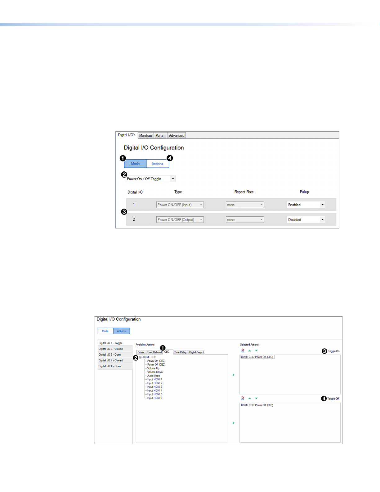
1. When the HD CTL 100 Configuration Software is opened, the Digital I/O's tab is
selected by default. If this tab is not selected, click it.
2. By default, the Mode screen is displayed with the Digital I/O's tab is selected. If it
is not, click the Mode button (see figure30, 1).
Figure 30. Digital I/O Mode Screen, Power On / Off Toggle Mode Selected
3. On the Digital I/O Mode screen, select Power On / Off Toggle (2).
When this mode is selected, Digital I/O ports 1 and 2 (3) are configured in Power
On/Off (Toggle) mode. (Power On/Off (Toggle) mode is available for only ports 1 and
2, however, ports 3 and 4 can be configured in other modes with different devices
attached).
33
4. Click the Actions button (4) to display the Available Actions and Selected
Actions panels.
5. In the Available Actions panel, select the CEC tab (see figure31, 1).
Figure 31. Configuring Digital I/O Port 1 in Power On/Off (Toggle) Mode
HD CTL 100 Controller • Application Example
33
Page 42

6. Click the + sign (2) to expand the list of CEC commands, and drag the Power On
(CEC) action to the Toggle On (top) panel to the right (3). This causes the controller
to send a command to the display to power on when the CCR 2BLB button is first
pressed.
When the CCR 2BLB button is pressed to power the display on, the button blinks
rapidly for approximately 10 seconds, then remains lit steadily.
NOTE: The number of seconds of warm-up and cool-down can be configured
7. Drag the Power Off (CEC) action from the Available Actions panel to the
Toggle Off (bottom) panel (4). This causes the controller to send a command to
the display to power off when the same CCR 2BLB button is pressed again.
(Alternatively, you can select each desired action in the Available Actions panel,
then click the green arrow between the panels to move the action to the Selected
Actions panel.)
When the CCR 2BLB button is pressed to again to power off the display, the button
blinks slowly for approximately 10 seconds, then remains dimly lit.
Occupancy Sensor
In this application, another means of powering on the display is by wiring a room
occupancy sensor, such as the Extron OCS 100, to the HD CTL 100 Digital I/O port
4, which is configured as an input. The sensor is mounted to the ceiling (figure26 on
page29). For the application, the HD CTL 100 is configured to power on the display
when the occupancy sensor detects that the room is occupied, and to power it off after a
specified period of no room occupancy.
via the Advanced screen of the HD CTL 100 Configuration software (see the
HD CTL 100 Configuration Software Help file for more information).
Digital I/O port states
The occupancy sensor is connected to Digital I/O port 4, which must be configured in
34
order for the sensor to trigger the desired power on and off actions. The Digital I/O port
can be in either of two states: open — (high) and closed (low). Each port consists of two
pins, signal and ground (one ground pin is shared between ports 1 and 2, while the other
is shared between ports 3 and 4).
Between the signal and ground pins, a circuit is either formed or broken when the
occupancy sensor is activated.
• The sensor provides approximately 21 VDC in the On (high or open) state and 0
VDC in the Off (low or closed) state. When wiring the blue or gray wires of the OCS
to Extron products with digital input ports, configure the ports as input with pullup
disabled, because the sensor has its own power supply.
• When the sensor detects motion, it instantly triggers an On state. Once occupancy is
no longer detected, the timer begins. If no motion is detected and the time expires,
then the sensor triggers the Off state.
HD CTL 100 Controller • Application Example
34
Page 43

Digital I/O port configuration procedure
To configure actions to be triggered by the two states of the occupancy sensor:
1. Select the Digital I/O's tab (see figure32, 1).
Figure 32. Configuring Digital I/O Port 4 as an Input for the Occupancy
Sensor
2. On the Digital I/O Configuration screen, click the Mode button (2).
3. From the second mode menu, located above the Digital I/O Port 3 panel (3),
select Digital Input / Output.
4. From the port 4 Type menu (4), select Input to configure port 4 as an input.
35
5. Click the Actions button to display the Available Actions and Selected
Actions panels.
6. In the left column of the Actions screen, select the Digital I/O 4 - Closed side
tab (see figure33, 1).
Figure 33. Adding the Power On (CEC) Action to the Digital I/O Port 4
Closed State
HD CTL 100 Controller • Application Example
35
Page 44
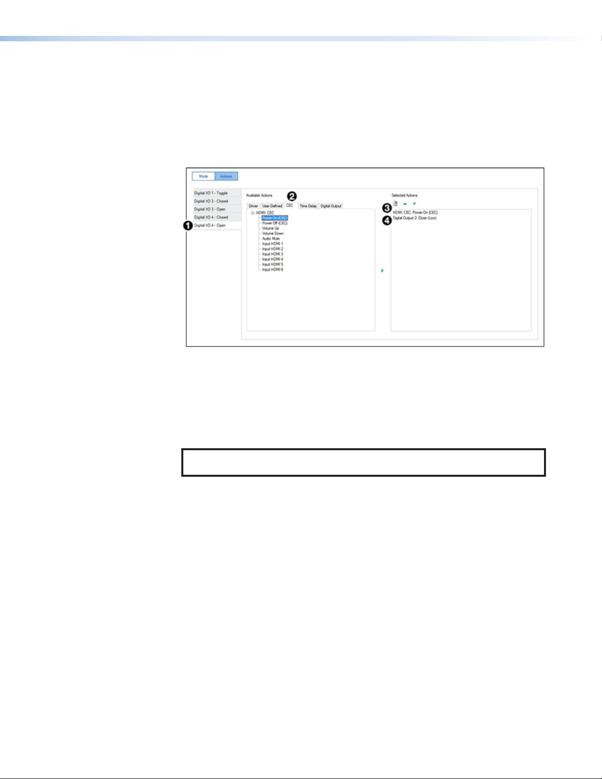
7. In the Available Actions panel, select the CEC tab (2) and click the + sign to
expand the list of HDMI CEC actions.
8. Drag the Power Off (CEC) action to the Selected Actions panel on the right (3).
This causes the HD CTL 100 to send a display power off command when the timer
on the occupancy sensor no longer detects that anyone is in the room.
9. To configure the Open state of Digital I-O 4, select the Digital I/O 4 - Open side
tab (see figure34, 1).
Figure 34. Adding the Digital Output 2 Open State to the Open State of
Digital I/O Port 4
10. In the Available Actions panel, select the CEC tab (2).
11. Drag the Power On (CEC) action to the Selected Actions panel on the right (3).
This causes the HD CTL 100 to send a display power on command when the timer
on the occupancy sensor detects that the room is occupied.
36
NOTE: See the OCS 100 Setup Guide, available at www.extron.com, for setup
detail for this sensor.
12. Drag the Digital Output - Open command to the Selected Actions panel (4).
This causes the LED of the CCR push-button switch to light steadily and keeps the
LED status in sync with the display power status.
Applying the Configuration
After completing configuring the screens for all the desired power on and off actions,
do the following to enable the configuration on the HD CTL 100 (see the HD CTL 100
Configuration Program Help File for the procedures):
1. Save the configuration as a project.
2. Upload the configuration to your HD CTL 100 unit.
HD CTL 100 Controller • Application Example
36
Page 45

Reference Information
Mounting the HD CTL 100
The HD CTL 100 can be set on a table, mounted on a rack shelf, or mounted under a
desk, podium, or table.
ATTENTION:
• Installation and service must be performed by authorized personnel only.
• L’installation et l’entretien doivent être effectués par le personnel autorisé
uniquement.
Tabletop Use
Four self-adhesive rubber feet are included with the HD CTL 100. For tabletop use, attach
one foot at each corner on the bottom of the unit, and place the controller where desired.
Rack Mounting
The HD CTL 100 can be mounted on a 9.5-inch, 6-inch, or 3.5-inch deep rack shelf.
They can also be mounted vertically to the front or back rack support. For mounting
procedures, see the instructions provided with the mounting kit.
UL rack mounting guidelines
The following Underwriters Laboratories (UL) guidelines pertain to the safe installation of
the equipment in a rack.
1. Elevated operating ambient temperature — If the equipment is installed in a
2. Reduced air flow — Install the equipment in a rack so that the amount of air flow
3. Mechanical loading — When mounting the equipment in the rack, ensure that
4. Circuit overloading — When connecting the equipment to the supply circuit,
5. Reliable earthing (grounding) — Maintain reliable grounding of rack-mounted
closed or multi-unit rack assembly, the operating ambient temperature of the rack
environment may be greater than room ambient temperature. Therefore, install the
equipment in an environment compatible with the maximum ambient temperature
(TMA = +122 °F, +50°C) specified by Extron.
required for safe operation of the equipment is not compromised.
uneven mechanical loading does not cause a hazardous condition.
consider the effect that circuit overloading might have on overcurrent protection and
supply wiring. Consider equipment nameplate ratings when addressing this concern.
equipment. Pay particular attention to supply connections other than direct
connections to the branch circuit (for example, use of power strips).
HD CTL 100 Controller • Reference Information 37
Page 46

Wall or Furniture Mounting
The HD CTL 100 can be mounted on a wall or under a desk, table, or podium using an
under-desk mounting kit such as the Extron MBU 125. Mounting kits and instructions are
available at www.extron.com.
TIP: Extron recommends wall-mounting the HD CTL 100 behind the display (place
the top panel of the unit against the wall), using a mounting kit such as the Extron
MBU 125 Under Desk Mounting Brackets (see figure35).
POWER
12V
0.3A MAX
INPUT
HD
MI
OUTPUT
HD
MI/CEC
DIGITAL I / O
21 G
+V OUT
43 G
IR / S
G24
S G
111
38
Figure 35. Mounting the HD CTL 100 to a Wall behind a Display
NOTE: Figure 35 shows the mounting brackets attached to the HD CTL 100 through
the bottom two holes in the bracket, closest to the wall (1). If you want to provide
space for air flow behind the unit, attach the brackets through the top two holes
(farthest from the wall).
HD CTL 100 Controller • Reference Information
38
Page 47

Extron Warranty
Extron Electronics warrants this product against defects in materials and workmanship for a period of three years
from the date of purchase. In the event of malfunction during the warranty period attributable directly to faulty
workmanship and/or materials, Extron Electronics will, at its option, repair or replace said products or components,
to whatever extent it shall deem necessary to restore said product to proper operating condition, provided that it is
returned within the warranty period, with proof of purchase and description of malfunction to:
USA, Canada, South America,
and Central America:
Extron Electronics
1230 South Lewis Street
Anaheim, CA 92805
U.S.A.
Europe and Africa:
Extron Europe
Hanzeboulevard 10
3825 PH Amersfoort
The Netherlands
Asia:
Extron Asia Pte Ltd
135 Joo Seng Road, #04-01
PM Industrial Bldg.
Singapore 368363
Singapore
This Limited Warranty does not apply if the fault has been caused by misuse, improper handling care, electrical
or mechanical abuse, abnormal operating conditions, or if modifications were made to the product that were not
authorized by Extron.
Japan:
Extron Electronics, Japan
Kyodo Building, 16 Ichibancho
Chiyoda-ku, Tokyo 102-0082
Japan
China:
Extron China
686 Ronghua Road
Songjiang District
Shanghai 201611
China
Middle East:
Extron Middle East
Dubai Airport Free Zone
F13, PO Box 293666
United Arab Emirates, Dubai
NOTE: If a product is defective, please call Extron and ask for an Application Engineer to receive an RA (Return
Authorization) number. This will begin the repair process.
USA: 714.491.1500 or 800.633.9876 Europe: 31.33.453.4040
Asia: 65.6383.4400 Japan: 81.3.3511.7655
Units must be returned insured, with shipping charges prepaid. If not insured, you assume the risk of loss or damage
during shipment. Returned units must include the serial number and a description of the problem, as well as the
name of the person to contact in case there are any questions.
Extron Electronics makes no further warranties either expressed or implied with respect to the product and its quality,
performance, merchantability, or fitness for any particular use. In no event will Extron Electronics be liable for direct,
indirect, or consequential damages resulting from any defect in this product even if Extron Electronics has been
advised of such damage.
Please note that laws vary from state to state and country to country, and that some provisions of this warranty may
not apply to you.
Contact Information
 Loading...