

Page 1
User Guide
Fiber Optic Extenders
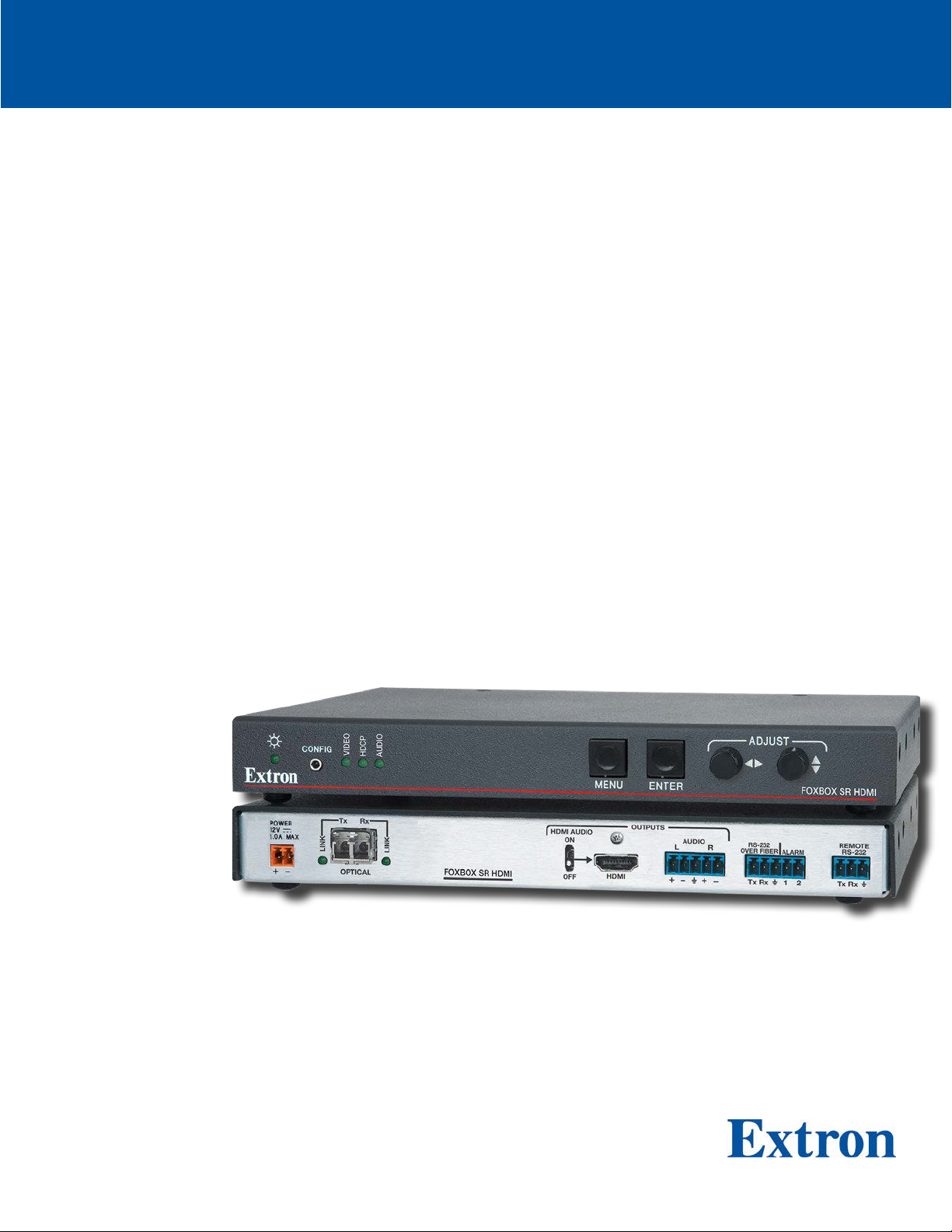
FOXBOX SR HDMI
Scaling Fiber Optic Receiver for HDMI, Audio, and RS-232
68-1990-01 Rev. B
12 20
Page 2
Safety Instructions
Safety Instructions • English
WARNING: This symbol, , when used on the product, is intended to
alert the user of the presence of uninsulated dangerous voltage within the
product’s enclosure that may present a risk of electric shock.
ATTENTION: This symbol, , when used on the product, is intended
to alert the user of important operating and maintenance (servicing)
instructions in the literature provided with the equipment.
For information on safety guidelines, regulatory compliances, EMI/EMF
compatibility, accessibility, and related topics, see the Extron Safety and
Regulatory Compliance Guide, part number 68-290-01, on the Extron
www.extron.com.
website,
Sicherheitsanweisungen • Deutsch
WARNUNG: Dieses Symbol auf dem Produkt soll den Benutzer darauf
aufmerksam machen, dass im Inneren des Gehäuses dieses Produktes
gefährliche Spannungen herrschen, die nicht isoliert sind und die einen
elektrischen Schlag verursachen können.
VORSICHT: Dieses Symbol auf dem Produkt soll dem Benutzer in
der im Lieferumfang enthaltenen Dokumentation besonders wichtige
Hinweise zur Bedienung und Wartung (Instandhaltung) geben.
Weitere Informationen über die Sicherheitsrichtlinien, Produkthandhabung,
EMI/EMF-Kompatibilität, Zugänglichkeit und verwandte Themen finden Sie in
den Extron-Richtlinien für Sicherheit und Handhabung (Artikelnummer
68-290-01) auf der Extron-Website, www.extron.com.
Instrucciones de seguridad • Español
ADVERTENCIA: Este símbolo, , cuando se utiliza en el producto,
avisa al usuario de la presencia de voltaje peligroso sin aislar dentro del
producto, lo que puede representar un riesgo de descarga eléctrica.
ATENCIÓN: Este símbolo, , cuando se utiliza en el producto, avisa
al usuario de la presencia de importantes instrucciones de uso y
mantenimiento recogidas en la documentación proporcionada con el
equipo.
Para obtener información sobre directrices de seguridad, cumplimiento
de normativas, compatibilidad electromagnética, accesibilidad y temas
relacionados, consulte la Guía de cumplimiento de normativas y seguridad
de Extron, referencia 68-290-01, en el sitio Web de Extron, www.extron.com.
Instructions de sécurité • Français
AVERTISSEMENT : Ce pictogramme, , lorsqu’il est utilisé sur le
produit, signale à l’utilisateur la présence à l’intérieur du boîtier du
produit d’une tension électrique dangereuse susceptible de provoquer
un choc électrique.
ATTENTION : Ce pictogramme, , lorsqu’il est utilisé sur le produit,
signale à l’utilisateur des instructions d’utilisation ou de maintenance
importantes qui se trouvent dans la documentation fournie avec le
matériel.
Pour en savoir plus sur les règles de sécurité, la conformité à la
réglementation, la compatibilité EMI/EMF, l’accessibilité, et autres sujets
connexes, lisez les informations de sécurité et de conformité Extron, réf.
68-290-01, sur le site Extron, www.extron.com.
Istruzioni di sicurezza • Italiano
AVVERTENZA: Il simbolo, , se usato sul prodotto, serve ad
avvertire l’utente della presenza di tensione non isolata pericolosa
all’interno del contenitore del prodotto che può costituire un rischio di
scosse elettriche.
ATTENTZIONE: Il simbolo, , se usato sul prodotto, serve ad avvertire
l’utente della presenza di importanti istruzioni di funzionamento e
manutenzione nella documentazione fornita con l’apparecchio.
Per informazioni su parametri di sicurezza, conformità alle normative,
compatibilità EMI/EMF, accessibilità e argomenti simili, fare riferimento
alla Guida alla conformità normativa e di sicurezza di Extron, cod. articolo
68-290-01, sul sito web di Extron,
www.extron.com.
Instrukcje bezpieczeństwa • Polska
OSTRZEŻENIE: Ten symbol, , gdy używany na produkt, ma na celu
poinformować użytkownika o obecności izolowanego i niebezpiecznego
napięcia wewnątrz obudowy produktu, który może stanowić zagrożenie
porażenia prądem elektrycznym.
UWAGI: Ten symbol, , gdy używany na produkt, jest przeznaczony do
ostrzegania użytkownika ważne operacyjne oraz instrukcje konserwacji
(obsługi) w literaturze, wyposażone w sprzęt.
Informacji na temat wytycznych w sprawie bezpieczeństwa, regulacji
wzajemnej zgodności, zgodność EMI/EMF, dostępności i Tematy pokrewne,
zobacz Extron bezpieczeństwa i regulacyjnego zgodności przewodnik, część
numer 68-290-01, na stronie internetowej Extron,
www.extron.com.
安全说明 • 简体中文
警告: 产品上的这个标志意在警告用户该产品机壳内有暴露的危险 电压,
有触电危险。
注意: 产品上的这个标志意在提示用户设备随附的用户手册中有
重要的操作和维护(维修)说明。
关于我们产品的安全指南、遵循的规范、EMI/EMF 的兼容性、无障碍
使用的特性等相关内容,敬请访问 Extron 网站 , www.extron.com,参见
Extron 安全规范指南,产品编号 68-290-01
。
Page 3
安全記事 • 繁體中文
警告: 若產品上使用此符 號,是為了提醒使用者,產品機殼內存在著
可能會導致觸電之風險的未絕緣危險電壓。
注意 若產品上使用此符號,是為了提醒使用者,設備隨附的用戶手冊中有
重 要 的 操 作 和 維 護( 維 修 )説 明 。
有關安全性指導方針、法規遵守、EMI/EMF 相容性、存取範圍和相關主題的詳細資
訊,請瀏覽 Extron 網站:www.extron.com,然後參閱《Extron 安全性與法規
遵守手冊》,準則編號 68-290-01。
안전 지침 • 한국어
경고: 이 기호 가 제품에 사용될 경우, 제품의 인클로저 내에 있는
접지되지 않은 위험한 전류로 인해 사용자가 감전될 위험이 있음을
경고합니다.
주의: 이 기호 가 제품에 사용될 경우, 장비와 함께 제공된 책자에 나와
있는 주요 운영 및 유지보수(정비) 지침을 경고합
안전 가이드라인, 규제 준수, EMI/EMF 호환성, 접근성, 그리고 관련 항목에
대한 자세한 내용은 Extron 웹 사이트(www.extron.com)의 Extron 안전 및
규제 준수 안내서, 68-290-01 조항을 참조하십시오.
니다.
安全上のご注意
• 日本語
警告: この記 号 が製品上に表示されている場合は、筐体内に絶縁されて
いない高電圧が流れ、感電の危険があることを示しています。
注意:この記号 が製品上に表示されている場合は、本機の取扱説明書に
記載されている重要な操作と保守( 整備)の 指示についてユーザーの注 意
を喚起するものです。
安全上のご注意、法規厳守、EMI/EMF適合性、その他の関連項目に
つ い て は 、エ ク ストロ ン の ウ ェ ブ サ イト www.extron.com よ り 『 Extron Safety
and Regulatory Compliance Guide』 ( P/N 68-290-01) をご覧ください。
Copyright
© 2012 — 2020 Extron. All rights reserved. www.extron.com
Trademarks
All trademarks mentioned in this guide are the properties of their respective owners.
®
The following registered trademarks (
), registered service marks (SM), and trademarks (TM) are the property of RGBSystems, Inc. or Extron (see
the current list of trademarks on the Terms of Use page at www.extron.com):
Registered Trademarks (
®
)
Extron, Cable Cubby, ControlScript, CrossPoint, DTP, eBUS, EDID Manager, EDID Minder, eLink, Flat Field, FlexOS, Glitch Free,
Global Configurator, GlobalScripter, GlobalViewer, Hideaway, HyperLane, IPIntercom, IPLink, KeyMinder, LinkLicense, LockIt, MediaLink,
MediaPort, NetPA, PlenumVault, PoleVault, PowerCage, PURE3, Quantum, ShareLink, Show Me, SoundField, SpeedMount, SpeedSwitch,
StudioStation, SystemINTEGRATOR, TeamWork, TouchLink, V-Lock, VideoLounge, VN-Matrix, VoiceLift, WallVault, WindoWall, XPA, XTP,
XTPSystems, and ZipClip
(SM)
Registered Service Mark
: S3 Service Support Solutions
Trademarks (™
)
AAP, AFL (Accu-RATEFrameLock), ADSP(Advanced Digital Sync Processing), Auto-Image, AVEdge, CableCover, CDRS(ClassD
Ripple Suppression), Codec Connect, DDSP(Digital Display Sync Processing), DMI (DynamicMotionInterpolation), DriverConfigurator,
DSPConfigurator, DSVP(Digital Sync Validation Processing), EQIP, Everlast, FastBite, Flex 55, FOX, FOXBOX, IP Intercom HelpDesk,
MAAP, MicroDigital, Opti-Torque, PendantConnect, ProDSP, QS-FPC(QuickSwitch Front Panel Controller), RoomAgent, Scope-Trigger, SIS,
SimpleInstructionSet, Skew-Free, SpeedNav, Triple-Action Switching, True4K, True 8k, Vector™ 4K , WebShare, XTRA, and ZipCaddy
Page 4

FCC Class A Notice
This equipment has been tested and found to comply with the limits for a Class A digital
device, pursuant to part15 of the FCC rules. The ClassA limits provide reasonable
protection against harmful interference when the equipment is operated in a commercial
environment. This equipment generates, uses, and can radiate radio frequency energy and,
if not installed and used in accordance with the instruction manual, may cause harmful
interference to radio communications. Operation of this equipment in a residential area is
likely to cause interference. This interference must be corrected at the expense of the user.
ATTENTION:
• The Twisted Pair Extension technology works with unshielded twisted pair (UTP)
•
NOTES:
• This unit was tested with shielded I/O cables on the peripheral devices. Shielded
• For more information on safety guidelines, regulatory compliances, EMI/EMF
or shielded twisted pair (STP) cables; but to ensure FCC Class A and CE
compliance, STP cables and STP Connectors are required.
La technologie extension pair
torsadées blindées(UTP) ou non blindées(STP). Afin de s’assurer de la
compatibilité entre FCC ClasseA et CE, les câbles STP et les connecteurs STP
sont nécessaires.
cables must be used to ensure compliance with FCC emissions limits.
compatibility, accessibility, and related topics, see the Extron Safety and
Regulatory Compliance Guide on the Extron website.
es torsadées fonctionne avec les câbles paires
Battery
CAUTION: Risk of explosion — Do not replace the battery with an incorrect type.
Dispose of used batteries according to the instructions.
ATTENTION : Risque d’explosion — Ne pas remplacer la pile par le mauvais type de
pile. Débarrassez-vous des piles usagées selon le mode d’emploi.
ATTENTION:
• If not provided with a power supply, this product is intended to be supplied by a UL
Listed power source marked “Class 2” or “LPS” and rated output 12Vdc, minimum
1.5 A or 56Vdc (PoE), minimum 0.8 A.
Si le pr
•
oduit n’est pas fourni avec une source d’alimentation, il doit être alimenté
par une source d’alimentation certifiée UL de classe 2 ou LPS, avec une tension
nominale 12 Vcc, 1.5 A minimum ou 56Vdc (PoE), minimum 0.8 A.
Page 5

Conventions Used in this Guide
Notifications
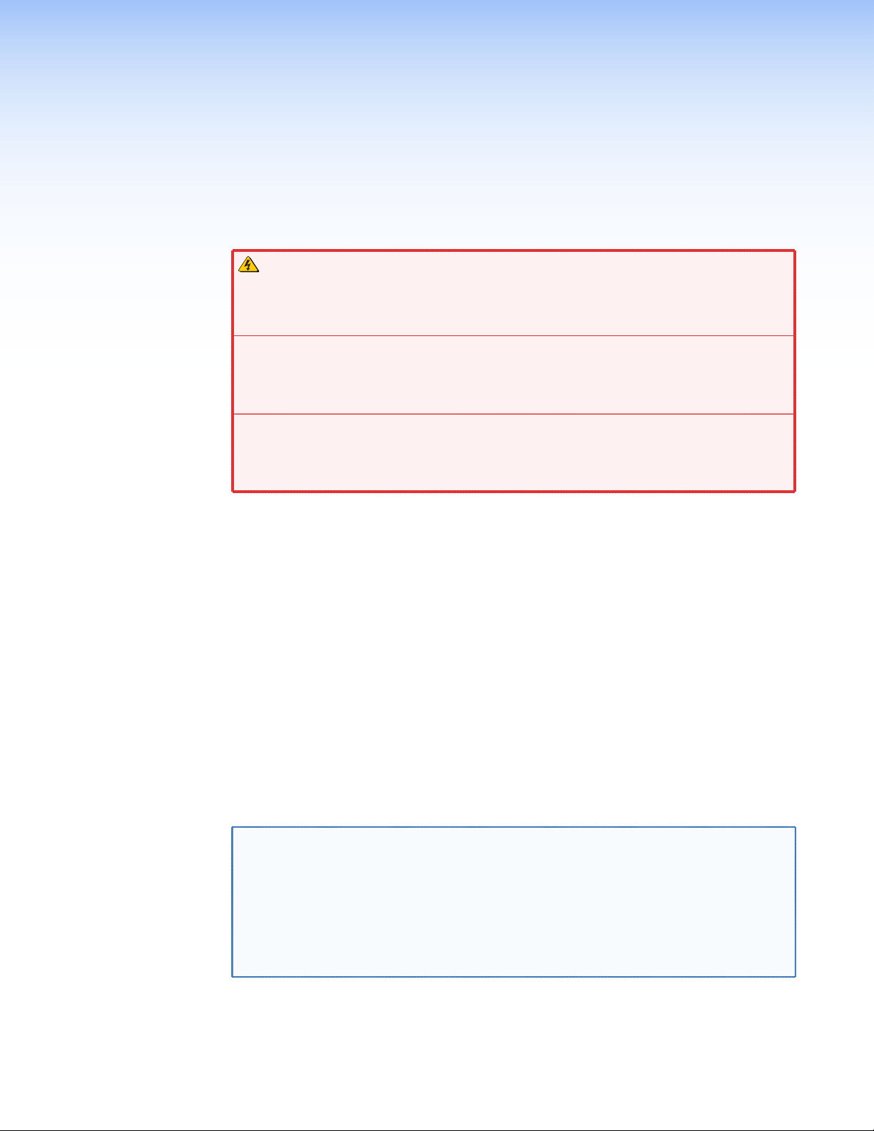
The following notifications are used in this guide:
ATTENTION:
• Risk of property damage.
•
Risque de dommages matériels.
NOTE: A note draws attention to important information.
Software Commands
Commands are written in the fonts shown here:
^AR Merge Scene,,0p1 scene 1,1 ^B 51 ^W^C.0
[01] R 0004
E X! *X1^* X1(* X2%* X2# CE}
NOTE: For commands and examples of computer or device responses used in this
guide, the character “0” is the number zero and “O” is the capital letter “o.”
Computer responses and directory paths that do not have variables are written in the font
shown here:
Reply from 208.132.180.48: bytes=32 times=2ms TTL=32
C:\Program Files\Extron
Variables are written in slanted form as shown here:
ping xxx.xxx.xxx.xxx —t
SOH R Data STX Command ETB ETX
Selectable items, such as menu names, menu options, buttons, tabs, and field names are
written in the font shown here:
From the File menu, select New.
Click the
00300 00400 00800 00600 [02] 35
OK button.
[17] [03]
Specifications Availability
Product specifications are available on the Extron website, www.extron.com.
Extron Glossary of Terms
A glossary of terms is available at http://www.extron.com/technology/glossary.aspx.
Page 6

Page 7

Contents
Introduction............................................................ 1
About this Guide ................................................. 1
About the FOXBOX SR HDMI ............................. 1
System Compatibility ...................................... 3
Cable Transmission Modes ............................. 3
Features ............................................................. 3
Installation .............................................................. 5
Rear Panel Features ........................................... 5
Making Connections ....................................... 8
Front Panel Configuration Port .......................... 12
Operation .............................................................. 14
Front Panel Indications and Controls ................ 14
Operation ......................................................... 15
Menu System Overview ................................ 15
Menu and Submenus ................................... 16
Remote Control ................................................... 22
Simple Instruction Set Control .......................... 22
Host-to-Unit Instructions ............................... 22
Symbol Definitions ........................................ 23
Unit-initiated Messages................................. 24
Error Responses ........................................... 24
Using the Command and Response Table .... 24
Command and Response Table for SIS
Commands ................................................. 25
Signal Processing Product Control Program ..... 29
Installing the Software ................................... 29
Starting the Program .................................... 29
Firmware Upgrade ........................................ 34
Mounting ............................................................... 38
Mounting the Unit ............................................. 38
Tabletop Use ................................................ 38
Mounting kits ................................................ 38
UL Rack-Mounting Guidelines ...................... 38
viiFOXBOX SR HDMI Encoder • Contents
Page 8

FOXBOX SR HDMI Encoder • Contents viii
Page 9
Introduction
WARNING: The FOXBOX SR HDMI outputs continuous invisible light, which may
be harmful to the eyes; use with caution.
AVERTISSEMENT : Le FOXBOX SR HDMI émet une lumière invisible en continu qui
peut être dangereux pour les yeux, à utiliser avec précaution.
Do not look into the r
•
cables themselves.
• Ne regardez pas dans les connecteurs de câble fibre optique sur le panneau arrière
ou dans les câbles fibre optique eux-mêmes.
Plug the attached dust caps into the optical transceivers when the fiber cable is
•
unplugged.
•
Branchez les pr
lorsque le câble fibre optique est débranché.
About this Guide
•
• About the FOXBOX SR HDMI
• Featur
es
ear panel fiber optic cable connectors or into the fiber optic
otections contre la poussière dans l’ensemble émetteur/récepteur
About this Guide
This guide contains information about the ultra-high performance Extron
FOXBOX SR HDMI scaling fiber optic receiver (see figure 1 on page 2).
About the FOXBOX SR HDMI
The FOXBOX SR HDMI is an ultra-high performance scaling fiber optic receiver that
accepts a proprietary optical signal on a single LC connector from a compatible fiber optic
transmitter or daisy-chained receiver located up to 30 km (18 miles) away.
The receiver outputs a single link of HDMI video, digital audio (embedded in the HDMI
output), analog audio, and RS-232 serial commands. The receiver can scale its video output
to one of several resolutions and rates.
NOTE: For HDCP compliance:
• A FOXBOX SR HDMI receiver must be paired with a FOXBOX HDMI or
• You must connect both fiber optic cables between the transmitter and
• A signal cannot be daisy-chained and retain HDCP compliance.
• The bidirectional Consumer Electronics Control (CEC) is not supported.
PowerCage FOX HDMI transmitter.
receiver.
FOXBOX SR HDMI • Introduction 1
Page 10
C
U
S
Projector
Local Monitor
HDMl
Extron
FOXBOX Tx HDMI
Fiber Optic Transmitter
HDMI
Blu-ray Player
Extron
FOXBOX SR HDMI
Fiber Optic Receiver
TouchLink
Control
System
RxTx
LINK
LINK
ALARM
OPTICAL
RS-232
OVER FIBER
FOXBOX Tx HDMI
Tx Rx 1 2
POWER
AUDIO INPUT
12V
1.0A MAX
HDMI
OUTPUTS
ON
HDMI AUDIO
HDMI
LINK
OFF
FOXBOX Rx HDMI
RxTx
LINK
POWER
12V
1.0A MAX
OPTICAL
™
VCR
DVD
DOC
CAM
LAPTOP
PC
ON
OFF
DISPLAY
MUTE
SCREEN
UP
SCREEN
DOWN
TCP/IP
®
100
RELAY
LINK
ACT
31
INPUT
IR
31
42
3
COM
1
42
TXRX
IPL 250
1
42
2
R
3
Up to 30 km (18.75 miles)
singlemode ber
SM Model
REMOTE
RS-232
ALARM
Tx Rx
RS-232
OVER FIBER
1 2
AUDIO
Tx Rx
L R
RS-232
HDMl
MPA 152
US
C
LISTED
17TT
AUDIO/VIDEO
APPARATUS
R
POWER
L
12V
3A MAX
Audio
Output
SPEAKER OUTPUTS!
INPUTS
OUTPUT
L
CLASS 2 WIRING
DO NOT GROUND
OR SHORT
R
L
Extron
SI 26X
Two-way Ceiling
Speakers
4/8
OHMS
R
REMOTE
VOL/MUTE
50mA
10V
Extron
MPA 152
Mini Power
Amplier
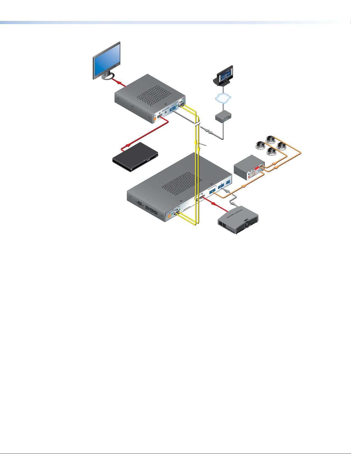
Figure 1. Typical FOXBOX SR HDMI Application
If the receiver is appropriately configured and has a second fiber optic cable installed, it also
can either:
• Receive an RS-232 return from a controlled device and send it to the transmitter via a
proprietary optical signal, or
• Output a daisy-chained signal to another receiver.
If either RS-232 return or daisy-chained communications are implemented, the receiver
outputs a proprietary signal on the second fiber optic cable carrying the signal.
For video resolutions up to 1600 x 1200, 1080p, or 1920 x 1200, the video output of the
receiver is a perfect, pixel-for-pixel recreation of the video signal input from the transmitter.
The single link of HDMI video output by a FOXBOX SR HDMI can be converted to DVI-D
video with the appropriate adapter.
The receiver has built-in color bars, crosshatch, grayscale, alternating pixels, and crop test
patterns, which are available under RS-232 Simple Instruction Set (SIS™) control, to assist
in setting up the display equipment and image and audio adjustments. The receiver has
image, audio, fiber light status, and lost-light alarm indicators.
FOXBOX SR HDMI • Introduction 2
Page 11

System Compatibility
The FOXBOX SR HDMI receiver operates interchangeably with all HDMI, DVI, and VGA
transmitters in the Extron FOXBOX, PowerCage FOX, and FOX 500 families, including Plus
and non-Plus units.
NOTES: • Although the receiver can operate with non-HDMI transmitters, the video
output is not HDCP-compliant.
• The receiver is not compatible with the FOX AV, PowerCage FOX AV,
FOX 3G HD-SDI, PowerCage FOX 3G HD-SDI, and FOX 3G DVC
transmitters.
Cable Transmission Modes
The receiver is further categorized by the type of fiber optic cable, multimode or singlemode,
which defines the effective range of transmission:
• Multimode (MM) — Long distance, up to 2 km (6,560 feet) (depending on the fiber
cable)
• Singlemode (SM) — Very long distance, up to 30 km (18.75 miles)
NOTE: The multimode and singlemode units are physically and functionally identical,
with the exception of the effective range of transmission. In this manual, any
reference applies to either transmission mode unless otherwise specified.
Features
Ultra high performance — The FOXBOX SR HDMI receives pixel-for-pixel HDMI or DVI-D
(with an adapter) video transmission, up to 1920 x 1200 at 60 Hz.
Video output — The receiver outputs a single link of HDMI video.
Compatible with the FOX Matrix Switchers, and FOX 500, FOXBOX, and
PowerCage FOX transmitters and receivers (with the exception of the FOX DA6,
FOX 2G, and FOX 3G HDSDI products)
Analog audio output — The receiver outputs balanced or unbalanced stereo audio on a
5-pole captive screw connector and digital audio embedded in the HDMI output.
Links monitoring — The receiver panel has indicators for monitoring image and audio
transmission and the fiber optic link.
Loss-of-light alarms — The receivers panel has discrete outputs that indicate if either of
the fiber optic links has suffered a loss of the light signal.
Signal Processing Product Control Program — For RS-232 remote control from a
PC, the Extron Signal Processing Product Control Program, which runs under Microsoft®
Windows®, provides a graphical interface with drag-and-drop, point-and-click operation.
Simple Instruction Set — The receiver uses SIS commandsfor easy remote control
operation.
Analog audio level — The analog audio output is at the consumer level (-10 dBV).
Auto Image™ — The auto imaging feature automatically sizes and centers the input to fill
the screen.
Upgradable firmware — The firmware that controls the operation of the receiver can be
upgraded in the field via an RS-232 link without taking the unit out of service. Firmware
upgrades are available for download on the Extron website, www.extron.com, and they
can be installed using the Signal Processing Product Control Program.
FOXBOX SR HDMI • Introduction 3
Page 12

Memory presets — 30 memory presets are a time-saving feature that lets you store input
size and position settings relative to a specific input resolution. You can then recall those
settings, when needed, using the SIS or the control software.
LockIt™ HDMI Cable Lacing Bracket — The receiver includes a LockIt bracket to secure
the HDMI cable to the unit.
Rack mounting — The receiver is rack mountable in any conventional 19-inch wide rack,
using an Extron 9.5-inch or 6-inch deep rack shelf.
Power — The 100 VAC to 240 VAC, 50-60 Hz external power supply provides worldwide
power compatibility.
FOXBOX SR HDMI • Introduction 4
Page 13
Installation
This sections details the installation of the FOXBOX SR HDMI, including:
• Rear Panel Features
• Front Panel Configuration Port
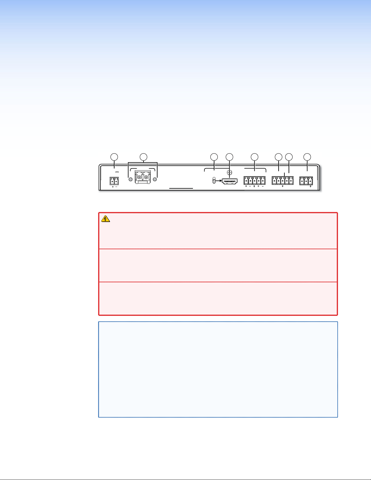
Rear Panel Features
1
43 28 5 76
POWER
12V
1.0 A MAX
LINK
OPTICAL
RxTx
LINK
FOXBOX SR HDMI
HDMI AUDIO
ON
OFF
OUTPUTS
HDMI
AUDIO
LR
RS-232
OVER FIBER
Tx Rx 1 2
ALARM
REMOTE
RS-232
Tx Rx
Figure 2. FOXBOX SR HDMI Scaling Receiver Rear Panel Features
WARNING: The FOXBOX SR HDMI outputs continuous invisible light, which may
be harmful to the eyes; use with caution.
AVERTISSEMENT : Le FOXBOX SR HDMI émet une lumière invisible en continu qui
peut être dangereux pour les yeux, à utiliser avec précaution.
•
Do not look into the r
ear panel fiber optic cable connectors or into the fiber optic
cables themselves.
•
egardez pas dans les connecteurs de câble fibre optique sur le panneau arrière
Ne r
ou dans les câbles fibre optique eux-mêmes.
• Plug the attached dust caps into the optical transceivers when the fiber cable is
unplugged.
•
Branchez les pr
otections contre la poussière dans l’ensemble émetteur/récepteur
lorsque le câble fibre optique est débranché.
NOTE: You can connect the transmitter to one or more receivers in one of three ways:
• One-way (transmitter Tx to receiver Rx) only — Connect fiber cable
from the transmitter Tx connector only.
• Two-way (transmitter to receiver and return) — Connect fiber cable
from the transmitter Tx connector and fiber cable Å back to the transmitter
Rx connector (see figure 3 on page 6).
• One-way (transmitter to receiver) with daisy chain (receiver to
receiver) — Connect fiber cable Ä from a fiber optic source and cable
to the next receiver in the daisy chain (see figure 4 on page 6). Set
Å
each receiver in the daisy chain to daisy chain mode. Up to 10 properlyconfigured receivers can be connected in a daisy chain to a single
transmitter.
Ä
Ä
FOXBOX SR HDMI • Installation 5
Page 14

a Fiber optic connectors and LEDs —
or Daisy-Chained
Receiver
Tr
Tx Rx
Ä Rx — For all one-way video, audio, and serial communications from the transmitter
to the receiver, connect a fiber optic cable to the Rx LC connector.
Connect the free end of this fiber optic cable to the Tx connector
on a FOXBOX Tx transmitter or to any other compatible Extron
FOXBOX device.
Å Tx (optional) — Connect a fiber optic cable to the Tx LC
connector for either of the following functions:
Normal configuration — For all one-way return serial
communications from the receiver to the Rx connector on a
compatible transmitter (see figure 3).
Daisy chain configuration — For daisy-chained video, audio,
and serial communications to the Rx connector on another
receiver (see figure 4).
1a
From Transmitter
Receiver
Tx Rx
1b
Figure 4. Daisy Chain Configuration
Connect the free end of this fiber optic cable to either of the following:
• The Rx connector on a compatible transmitter or to any other compatible
Extron FOX device
• The Rx connector on another receiver in the daisy chain
1a
Tx Rx
Receiver
1b 1a
Receiver
ansmitter
Figure 3. Two Way
Configuration
Tx Rx
NOTES: • Ensure that you use the proper fiber cable for your transmitter/
receiver pair. Typically, singlemode fiber has a yellow jacket and
multimode cable has an orange or aqua jacket.
• Only one fiber optic cable, transmitter-Tx-to-receiver-Rx, is required
for video, audio, and serial command transmission. However, if you
connect only one fiber optic cable, or if your receiver is configured to
daisy-chain the optical signal:
• The HDMI signal output by the receiver is not HDCP-compliant.
• You will not receive RS-232 reports from the controlled device.
To receive responses from the controlled device and for
HDCP compliance, you need to install both fiber optic
cables and leave link 2 enabled (via an SIS command
[see page 27] to the receiver or using the Signal Processing
Product Control Program [see page 33]).
Tx Link and Rx Link LEDs — When lit, the link is active (light is received).
NOTE: The Tx connector emits light in either case and the Rx port receives
light.
b HDMI Output connector — Connect a video display to this HDMI connector (see
“HDMI connector“ on page 8 for pin assignments).
c HDMI Audio switch — This switch mutes (Off position) and unmutes (On position) the
embedded audio output on the HDMI output connector. The audio on the captive screw
output always remains active regardless of the setting of this switch.
FOXBOX SR HDMI • Installation 6
Page 15
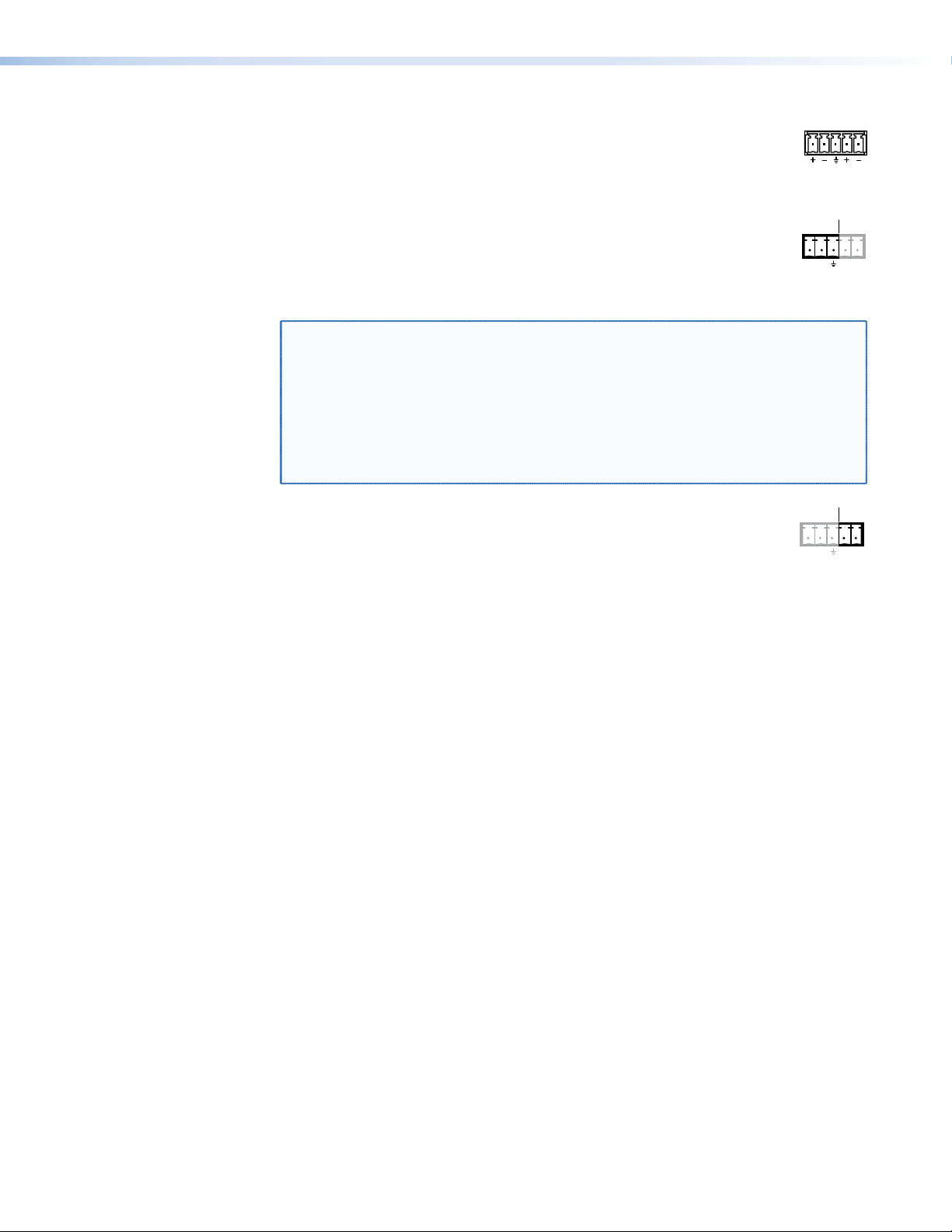
d Audio output connector — Connect audio devices, such as an audio
LR
AUDIO
ALARM
Tx Rx 1 2
RS-232
ALARM
Tx Rx 1 2
RS-232
amplifier or powered speakers to this 5-pole, 3.5 mm captive screw
connector to output the transmitted, unamplified, line level audio (see “Audio
output connector“ on page 10 to wire a captive screw connector for the
appropriate output type and impedance level).
e RS-232 Over Fiber port — If you want the FOXBOX to pass serial
OVER FIBER
command signals to a secondary device, for serial control of a projector for
example, connect the secondary device to the receiver via the first three
leftmost poles (Tx, Rx, and _) of this 5-pole captive screw connector (see
“RS-232 connections“ on page 9 to wire this connector).
NOTES: • If you connect only one fiber optic cable (item Ä, on page 6), or you
configure the receiver for daisy-chaining, you will not receive reports
from the controlled device. To receive responses from the controlled
device, you must install two fiber optic cables and leave link 2 enabled
(via an SIS command [see page 27] or using the Signal Processing
Product Control Program [see page 33]).
• The FOXBOX can pass RS-232 commands and responses at rates up to
115200 baud.
f Alarm outputs port — For remote monitoring of the status of fiber optic
OVER FIBER
link 1, connect a locally-constructed or furnished monitoring device to the
receiver via the two rightmost poles (1 and 2) of this 5-pole captive screw
connector. When the receiver does not detect a light link on fiber cable Rx,
pin 1 and pin 2 of this port are shorted together (see “Alarm outputs connection“ on
page 9 to wire this connector).
g Remote RS-232 port — For serial control of the receiver, connect a host device,
such as a computer, touch panel control, or RS-232 capable PDA, to the transmitter via
this 3-pole captive screw connector (see “RS-232 connections“ to wire this connector
(see “Remote Control“ on page 20 for SIS commands and software control).
connector (see “Power supply wiring“ on page 11, to wire the connector).
h DC power connector — Plug the included external 12 VDC power supply into this
FOXBOX SR HDMI • Installation 7
Page 16

Making Connections
71
01
1
19
HDMI connector
Figure 5 defines the HDMI pin assignments.
19
18 2
Type A Receptacle
1
HDMI
HDMI
Type A Plug
182
Pin Signal
TMDS data 2+
1
TMDS data 2
2
shield
TMDS data 2-
3
41
TMDS data 1+ TMDS clock+
TMDS data 1
5
shield
TMDS data 1-
6
Pin Pin Signal Signal
TMDS data 0–
TMDS data 0
8
shield
TMDS data 0-
9
TMDS clock
11 17
shield
TMDS clock- +5 V power
12 18
CEC control
3
14
15
19
Reserved
6
DDC / CEC
Hot plug detect
(NC)
SCL
SDA
Ground
Figure 5. HDMI Connectors
HDMI signals run at a very high frequency and are especially prone to errors caused by bad
video connections, too many adapters, or excessive cable length. To avoid the loss of an
image or jitter, follow these guidelines:
• Do not exceed 16.4 feet (5 meters) on the input of the transmitter or the output of the
FOXBOX SR HDMI scaling receiver.
• Use only the cable designed for HDMI signals that is supplied by Extron.
• Limit or avoid the use of adapters.
• Use only cables specifically intended for HDMI or DVI signals. Use of non-HDMI or
non-DVI cables or modified cables can result in a missing video output.
To securely fasten an HDMI cable to a device:
1.
Plug the HDMI cable into the panel connection (see a in figure 6).
3
1
Figure 6. Installing the LockIt Lacing Bracket
2. Loosen the HDMI connection mounting screw from the panel enough to allow the
LockIt lacing bracket to be placed over it (
4
3
2
5
). The screw does not have to be removed.
b
FOXBOX SR HDMI • Installation 8
Page 17

3. Place the LockIt lacing bracket on the screw and against the HDMI connector, then
RS-232
REMOTE
FunctionPin
Do not tin the wires!
RS-232
tighten the screw to secure the bracket (c).
ATTENTION:
• Do not overtighten the HDMI connector mounting screw. The shield to which it
fastens is very thin and can easily be stripped.
•
Ne serr
ez pas trop la vis de montage du connecteur HDMI. Le blindage auquel
elle est attachée est très fin et peut facilement être dénudé.
4.
Loosely place the included tie wrap ar
bracket (
d
).
ound the HDMI connector and the LockIt lacing
5. While holding the connector securely against the lacing bracket, use pliers or similar
tools to tighten the tie wrap, then remove any excess length (e).
RS-232 connections
The Remote RS-232 port on the receiver only is for remote control of the receiver. The
RS-232 Over Fiber port on both units is for transmission of serial signals, such as projector
control signals, between the transmitter and receiver (see figure 7 to properly wire the
connectors).
RS-232
Tx Rx
NOTE: Cross the Tx and Rx lines once between the source and the target.
Figure 7. RS-232 Over Fiber Connector
ALARM
OVER FIBER
Tx Rx 1 2
Do not tin the wires!
Ground ( )
Receive (Rx)
Transmit (Tx)
Bidirectional
Tx
Transmit data
Rx
Receive data
Gnd
Signal ground
Controlling
Device
Ground ( )
Receive (Rx)
Transmit (Tx)
NOTE: The length of exposed wires is critical. The ideal length is 3/16 inch (5 mm).
• Longer bare wires can short together.
• Shorter wires are not as secure in the connectors and could be pulled out.
Alarm outputs connection
ALARM
OVER FIBER
Tx Rx 1 2
Figure 8. Alarm Connector
NOTE: The length of exposed wires is critical (see the second RS-232 connector
Pin 1 and pin 2 are
shorted together when
no light is detected.
NOTE, above.)
FOXBOX SR HDMI • Installation 9
Page 18

Audio output connector
Unbalanced Stereo Output Balanced Stereo Output
Do not tin the wires!
Tip
NO GROUND HERE
NO GROUND HERE
Tip
LR
Sleeves Sleeves
Tip
Ring
Tip
Ring
LR
See figure 9 to properly wire a captive screw output connector. The connector is included
with the receiver, but you must supply the audio cable. Use the supplied tie-wrap to strap
the audio cable to the extended tail of the connector.
Figure 9. Captive Screw Connector Wiring for Stereo Audio Output
ATTENTION:
• For unbalanced audio, connect the sleeves to the ground contact. DO NOT connect
the sleeves to the negative (-) contacts.
Pour l’audio asymétrique, connectez les manchons au contact au sol.
•
connecter les manchons aux contacts négatifs (–).
NOTE: The length of exposed wires is critical (see the RS-232 connector NOTE on
page 9 for more information.)
NE PAS
FOXBOX SR HDMI • Installation 10
Page 19

Power supply wiring
Connector
Smooth
AA
ATTENTION:
• Always use a power supply provided by or specified by Extron. Use of an
unauthorized power supply voids all regulatory compliance certification and may
cause damage to the supply and the unit.
•
Utilisez toujours une sour
L’utilisation d’une source d’alimentation non autorisée annule toute conformité
réglementaire et peut endommager la source d’alimentation ainsi que le produit final.
Figure 10 shows how to wire the power connector.
Ridges
ce d’alimentation fournie ou recommandée par Extron.
SECTION A–A
Power Supply
Output Cord
Tie Wrap
Captive Screw
3
5
Figure 10. Power Connector Wiring
CAUTION:
ATTENTION :
• The wires must be kept separate while the power supply is plugged in. Remove
power before wiring.
• Les deux cordons d’alimentation doivent être tenus à l’écart l’un de l’autre quand
l’alimentation est branchée.
• The length of exposed wires is important. The ideal length is 3/16 inch (5 mm).
• Any longer and the exposed wires may touch, causing a short circuit between
them.
• Any shorter and the wires can be easily pulled out even if tightly fastened by the
captive screws.
• La longueur des câbles exposés est importante. La longueur idéale est de 5mm
(3/16inches).
• S’ils sont un peu plus longs, les câbles exposés pourraient se toucher et
provoquer un court circuit.
• S’ils sont un peu plus courts, ils pourraient sortir, même s’ils sont attachés par
les vis captives.
• Do not tin the power supply leads before installing them in the connector. Tinned
wires are not as secure in the connector and could be pulled out.
• Ne pas étamer les conducteurs avant de les insérer dans le connecteur. Les câbles
étamés ne sont pas aussi bien fixés dans le connecteur et pourraient être retirés.
FOXBOX SR HDMI • Installation 11
Page 20

ATTENTION:
• This product is intended to be supplied by a UL Listed power source marked “Class
2” or “LPS,” rated 12 VDC, 1.0 A minimum. Always use a power supply supplied
by or specified by Extron. Use of an unauthorized power supply voids all regulatory
compliance certification and may cause damage to the supply and the end product.
•
oduit est destiné à une utilisation avec une source d’alimentation listéeUL
Ce pr
avec l’appellation «Classe2» ou «LPS» et normée 12Vcc, 1,0A minimum. Utilisez
toujours une source d’alimentation fournie ou recommandée par Extron. L’utilisation
d’une source d’alimentation non autorisée annule toute conformité réglementaire et
peut endommager la source d’alimentation ainsi que le produit final.
• Unless otherwise stated, the AC/DC adapters are not suitable for use in air handling
spaces or in wall cavities.
•
Sauf mention contrair
e, les adaptateurs AC/DC ne sont pas appropriés pour une
utilisation dans les espaces d’aération ou dans les cavités murales.
The installation must always be in accor
•
dance with the applicable provisions of
National Electrical Code ANSI/NFPA 70, article 725 and the Canadian Electrical
Code part 1, section 16. The power supply shall not be permanently fixed to a
building structure or similar structure.
•
Cette installation doit toujours êtr
e en accord avec les mesures qui s’applique au
National Electrical Code ANSI/NFPA70, article725, et au Canadian Electrical Code,
partie1, section16. La source d’alimentation ne devra pas être fixée de façon
permanente à une structure de bâtiment ou à une structure similaire.
• Power supply voltage polarity is critical. Incorrect voltage polarity can damage the
power supply and the unit. The ridges on the side of the cord (see figure 10 on
page 11) identify the power cord negative lead.
• La polarité de la source d’alimentation est primordiale. Une polarité incorrecte
pourrait endommager la source d’alimentation et l’unité. Les stries sur le côté du
cordon (voir l’illustration 10 sur la page 11) permettent de repérer le pôle négatif du
cordon d’alimentation.
To verify the polarity before connection, plug in the power supply with no load and check the
output with a voltmeter.
Use the supplied tie wrap to strap the power cord to the extended tail of the connector.
Alternatively, an optional Extron PS 124 Universal 12 VDC Power Supply can power multiple
Extron 12 VDC devices using only one AC power connector.
Front Panel Configuration Port
1
CONFIG
Figure 11. FOXBOX SR Scaling Receiver Front Panel Features
a Configuration port — Connect a controlling device, such as a PC, to this port via
a 2.5 mm mini jack TRS RS-232 cable for RS-232 protocol control of all FOXBOX
functions.
The optional 9-pin D to 2.5 mm mini jack TRS RS-232 cable, part number 70-335-01
(figure 12) can be used for this connection.
VIDEO
HDCP
AUDIO
FOXBOX SR HDMI • Installation 12
Page 21

NOTE: This port is for remote control of the receiver, not for the over fiber RS-232
5
1
(Gnd)
link.
6 feet
(1.8 m)
6
9
9-pin D Connection TRS Plug
Pin 2 Rx line on the computer Tip
Pin 3 Tx line on the computer Ring
Pin 5 Signal ground on the computer Sleeve
Part #70-335-01
Tip
Ring
Sleeve
Figure 12. 9-pin TRS RS-232 cable
This port is RS-232 only, with the following protocols:
• 9600 baud • no parity • 8 data bits
• 1 stop bit • no flow control
NOTE: The maximum distances from the transmitter or receiver to the controlling
device can vary up to 200 feet (61 m). Factors such as cable gauge, baud
rates, environment, and output levels (from the unit and the controlling
device) all affect transmission distance. Distances of about 50 feet (15 m)
are typically not a problem. In some cases, the unit may be capable of serial
communications via RS-232 up to 250 feet (76 m) away.
See “Remote Control“ on page 22 for definitions of the SIS commands (serial
commands to control the transmitter via this connector) and software control.
FOXBOX SR HDMI • Installation 13
Page 22

Operation
This sections details the installation of the FOXBOX SR HDMI, including:
• Front Panel Indications and Controls
• Operation
Front Panel Indications and Controls
The receiver has front panel LEDs that indicate power and signal status (see figure 13)
and a menu system that is operated using the front panel controls and displayed on the
connected output device.
1 3 4
CONFIG
Figure 13. FOXBOX SR HDMI Front Panel Indications and Controls
2 5
AUDIO
HDCP
VIDEO
MENU ENTER
ADJUST
FOXBOX SR HDMI
a Power LED — This LED lights to indicate that power is applied to the unit.
b Signal indicators —
Video LED — This LED lights when the receiver accepts a video signal on the fiber
optic input.
HDCP LED — This LED lights when the output signal is HDCP encrypted.
Audio LED — This LED lights on the receiver when the transmitter detects an audio
signal above a –35 dB minimum threshold. It returns to unlit if the audio signal drops
below the threshold for 10 seconds.
c Menu button — The Menu button enters the main menu system of the receiver and
backs out of the currently active submenu or selection.
NOTE: See “Menu and Submenus” on page 16 for the detailed menu system
interoperability of the Menu button, Enter button (d), and Adjust knobs
(e). The menu system is displayed on the connected video output device
(see figure 14 on page 15).
d Enter button — The Enter button selects and deselects a highlighted submenu or
function in the receiver main menu system and saves a changed value.
e Adjust
knobs change settings when used in conjunction with the menu system.
{
(horizontal) and Adjust { (vertical) knobs — The Adjust [ and Adjust
[
FOXBOX SR HDMI • Operation 14
Page 23

Operation
Menu Controls
HDMI
ADJU
Menu System Overview
After the transmitter, all receivers, and their connected devices are powered up, the system
is fully operational. If any problems are encountered, verify that the cables are routed and
connected properly, and that all display devices have identical resolutions and refresh rates.
If your problems persist, call the Extron S3 Sales & Technical Support Hotline (see the
contact numbers listed on the Extron web page for the office nearest you).
Access the various adjustments and test patterns available in the FOXBOX receiver via the
menu system. The menus and submenus are displayed on the connected video output
device (see figure 14).
EXTRON ELECTRONICS FOXBOX SR HDMI
AUTO IMAGE
PICTURE CONTROLS
USER PRESETS
OUTPUT
CONFIGURATION
ADVANCED
CONFIGURATION
ADJUST
FOXBOX SR HDMI
MENU ENTER
AUDIO
HDCP
VIDEO
CONFIG
Figure 14. Menu System Display
FOXBOX SR HDMI • Operation 15
Page 24

Menu and Submenus
Menu
No
menu
display
Menu
Timeout
Timeout
Timeout
Timeout
Timeout
AUTO IMAGE
EXTRON ELECTRONICS FOXBOX SR HDMI
PICTURE CONTROLS
OUTPUT
CONFIGURATION
USER PRESETS
ADVANCED
CONFIGURATION
• Automatically size and center the input to fill the screen
• Position • Brightness • Detail filter
• Size • Contrast
• Save presets • Clear presets • Recall presets
• Resolution • Rate • HDMI format
• Test pattern • Aspect ratio • Menu timeout
• Blank • Auto memory
• Freeze • Reset
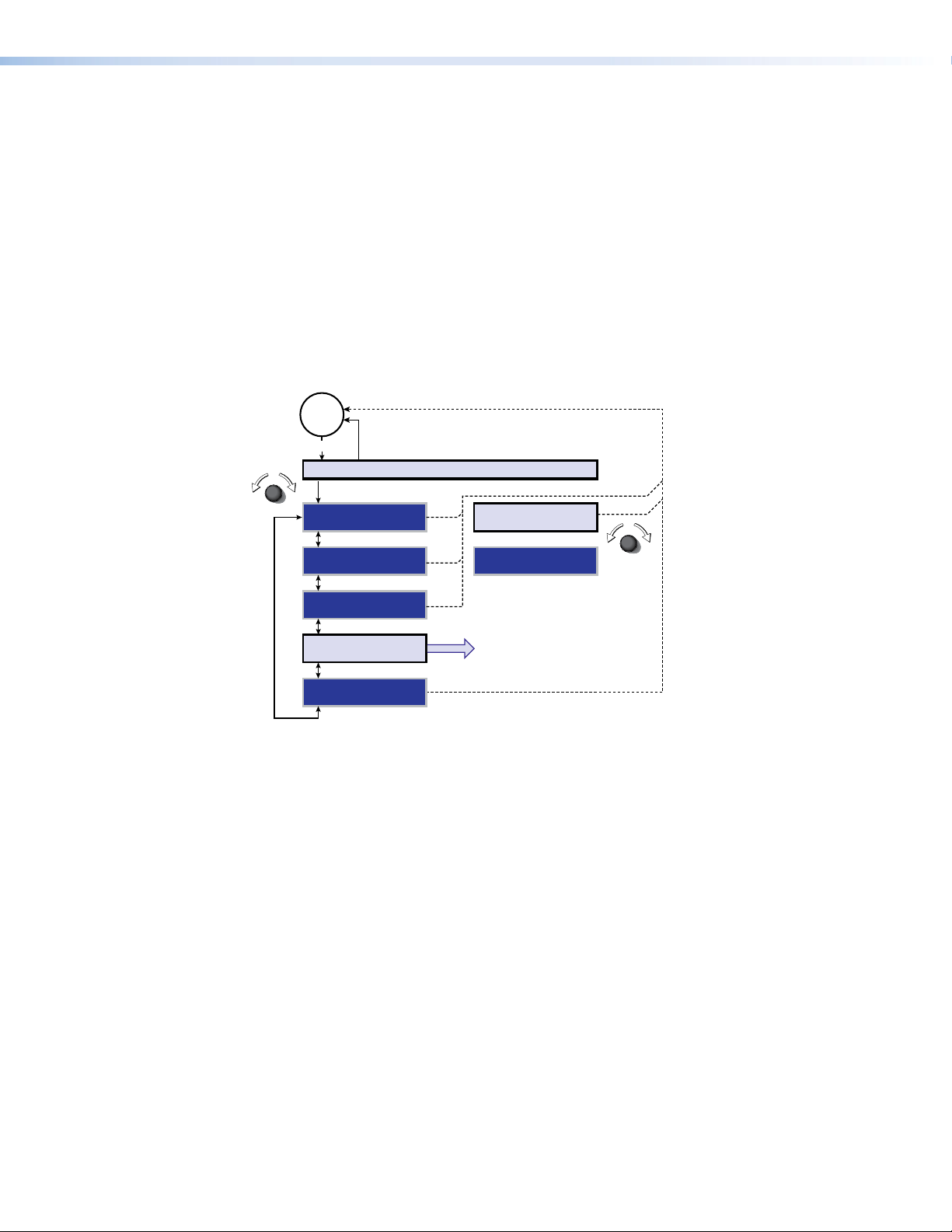
Figure 15 shows a flowchart of the submenus in the main menu system. Each submenu
leads to one or more a series of submenus or to “slider” type status indicator bar controls
that accomplish individual tasks or groups of tasks.
NOTE: In figure 15, and all other flowcharts in this chapter, solid lines indicate screen
changes initiated by the operator. Dashed lines indicate screen changes that are
the result of a timeout function.
Figure 15. Menu System Flowchart
Menu button — Press the Menu button to activate the menu system and to back out of a
selected menu or submenu.
Enter button — Press the Enter button to select a highlighted menu or submenu and to
execute or save a selected variable.
Adjust [ and Adjust { knobs — When the menu system is active, rotate the Adjust [
knob and Adjust { knob to scroll through the main menu or selected layer of submenus and
to adjust a selected setting.
Press the Menu button to activate the main menu in the on-screen display. Rotate either
Adjust knob to select (highlight) the desired selection and then press the Enter button. The
submenus for that menu item appear. Rotate either Adjust knob to select (highlight) the
desired submenu and press the Enter button.
NOTES: • If you press the Menu button while a submenu is active, the on-screen
• From any menu or submenu, after a user-selectable period of inactivity, the
• The Adjust knobs have no mechanical limits to their rotation.
display backs up to display the main menu from which that submenu was
selected.
scaler saves all adjustment settings and deactivates the on-screen display.
FOXBOX SR HDMI • Operation 16
Page 25

Auto Image submenu
Figure 16 shows an overview of the Auto Image submenu and executing the Auto-Image™
function. Select Auto Image and press the Enter button twice to automatically size and
center the input to fit the output resolution.
No
menu
display
Menu
EXTRON ELECTRONICS FOXBOX SR HDMI
Menu
AUTO IMAGE PRESS ENTER TO
PICTURE CONTROLS
USER PRESETS
OUTPUT
CONFIGURATION
ADVANCED
CONFIGURATION
Enter
AUTO IMAGE
Timeout
Timeout
Timeout
Timeout
Timeout
Figure 16. Auto Image Submenu Flowchart
Picture Controls submenu
Figure 17 shows an overview of the Picture Controls submenu and the available selections.
No
menu
display
Menu
EXTRON ELECTRONICS FOXBOX SR HDMI
Menu
AUTO IMAGE H POSITION V
Timeout
+0 +0
PICTURE CONTROLS
USER PRESETS
OUTPUT
CONFIGURATION
ADVANCED
CONFIGURATION
Enter
H SIZE V
1280 720
Timeout
Timeout
Timeout
BRIGHT CONT
128 128
DETAIL
64
Figure 17. Picture Controls Submenu Flowchart
Position selection
The Position selection allows you to adjust the horizontal and vertical position of the image.
Rotate the Adjust [ knob while this submenu is active to shift the image horizontally and
the Adjust { to shift the image vertically.
FOXBOX SR HDMI • Operation 17
Page 26

Size selection
The Size selection allow you to adjust the horizontal and vertical size of the output. Rotate
the Adjust [ knob while this submenu is active to size the image horizontally and the
Adjust { to size the image vertically.
Brightness and Contrast selection
Rotate the Adjust [ knob while this submenu is active to increase and decrease the image
brightness, from 0 through 255. Rotate the Adjust { to increase and decrease the image
contrast, from 0 through 255.
Detail selection
Rotate either Adjust knob while this submenu is active to increase and decrease the detail
filter, from 0 through 127.
User Presets submenu
Figure 18 shows an overview of the User Presets submenu and the available selections.
No
menu
display
Menu
EXTRON ELECTRONICS FOXBOX SR HDMI
Menu
AUTO IMAGE RECALL
PICTURE CONTROLS
USER PRESETS
OUTPUT
CONFIGURATION
ADVANCED
CONFIGURATION
Timeout
Timeout
Enter
Timeout
Timeout
1
SAVE
1
CLEAR
1
Figure 18. User Presets Submenu Flowchart
User presets are saved in nonvolatile memory; when the receiver is powered down and later
powered back up, the settings are available for selection. Saving the settings to a preset
overwrites the settings previously written to that preset.
NOTE: The User Preset is tailored for the selected output rate. If you change the output
rate and then recall a preset that was saved for a different rate, the preset
adjustments have no effect on the video output. If, however, you then change to
the rate for which the preset was saved, the effects of the adjustments appear
on the screen.
Recall submenu
Rotate either Adjust knob while this submenu is active to select a preset number, from
1 through 30, and press the Enter button to recall the selected preset to be the current
settings. Allow the screen to timeout without pressing the Enter button to exit without
recalling the settings.
FOXBOX SR HDMI • Operation 18
Page 27
Save submenu
Rotate either Adjust knob while this submenu is active to select a preset number, from 1
through 30, and press the Enter button to save the current settings to the selected preset.
Allow the screen to timeout without pressing the Enter button to exit without saving the
settings.
Clear submenu
Rotate either Adjust knob while this submenu is active to select a preset number, from 1
through 30, and press the Enter button to erase the selected preset. Allow the screen to
timeout without pressing the Enter button to exit without erasing the settings.
Output Configuration submenu
Figure 19 shows an overview of the Output Configuration submenu and the available
selections.
No
menu
display
Menu
EXTRON ELECTRONICS FOXBOX SR HDMI
Menu
AUTO IMAGE RESOLUTION
PICTURE CONTROLS
USER PRESETS
OUTPUT
CONFIGURATION
ADVANCED
CONFIGURATION
Figure 19. Output Configuration Submenu Flowchart
Timeout
Timeout
Timeout
Timeout
Enter
Timeout
720p@60
HDMI FORMAT
YUV 422 FULL
Resolution submenu
Rotate either Adjust knob while this submenu is active to select the output resolution and
refresh rate (see the table for variable X& on page 24 for a list of available selections).
HDMI Format submenu
Rotate either Adjust knob while this submenu is active to select an HDMI format for the
output (see the list below for available selections).
• Auto (HDMI 444 or DVI 444) • DVI RGB 444 • HDMI RGB 444
• HDMI RGB 444 limited • HDMI YUV 444 full • HDMI YUV 444 limited
• HDMI YUV 422 full • HDMI YUV 422 limited
FOXBOX SR HDMI • Operation 19
Page 28

Advanced Configuration submenu
Split Color Bars
Alt Pixels Crop
Figure 20 shows an overview of the Advanced Configuration submenu and the available
selections.
No
menu
display
Menu
EXTRON ELECTRONICS FOXBOX SR HDMI
Menu
AUTO IMAGE TEST PATTERN
PICTURE CONTROLS
USER PRESETS
OUTPUT
CONFIGURATION
ADVANCED
CONFIGURATION
Timeout
Timeout
Timeout
Timeout
Enter
NONE
BLANK
OFF
FREEZE
OFF
ASPECT RATIO
FILL
AUTO MEMORY
ON
FACTORY RESET
HOLD ENTER
MENU TIMEOUT
5
Figure 20. Advanced Configuration Submenu Flowchart
Test Pattern submenu
The Test Pattern submenu lets you select from among several test patterns. The test
patterns are helpful when you are adjusting the connected displays for color, convergence,
focus, resolution, contrast, grayscale, and aspect ratio.
Rotate either Adjust knob while this submenu is active to select a test pattern or to turn the
test pattern off (none). The available test patterns are: color bars, crosshatch, grayscale,
alternating pixels, and crop (see figure 21). The crop pattern available from the submenu
varies depending on the aspect ratio of the output rate.
Crosshatch 4x4 Split Grayscale
Figure 21. Test Patterns
Blank submenu
The Blank submenu controls the video mute function. Rotate either Adjust knob while this
submenu is active to select either On to blank the screen or Off to output video.
Freeze submenu
The Freeze submenu lets you freeze and unfreeze the video output. Rotate either Adjust
knob while this submenu is active to select either On (freeze) or Off (unfreeze).
NOTE: The freeze function has no effect on the audio output.
FOXBOX SR HDMI • Operation 20
Page 29

Aspect Ratio submenu
The Aspect Ratio submenu lets you specify how the scaler handles the aspect ratio of a
scaled output. Rotate either Adjust knob while this submenu is active to select either Fill to
force the input to automatically fill the output raster or Follow Input to display the input in its
native aspect ratio.
Auto Memory submenu
The Auto Memory submenu provides a means to toggle the auto memory feature on or off.
by rotating either Adjust knob while this submenu is active.
Auto memory saves and recalls centering, sizing, and filtering information, based on the
input frequency. Auto memory settings may conflict with user preset settings. When you
use a control system to switch inputs and then recall a user memory, the delay in recalling
the auto memory settings could result in the recalled auto memory settings overwriting the
recalled user preset settings. To prevent this conflict, turn auto memory off.
Factory Reset submenu
The Factory Reset submenu forces the receiver to reset to the default values. Press and
hold the Enter button while this submenu is active for about 3 seconds, then release the
Enter button.
Menu Timeout submenu
The Menu Timeout submenu lets you set how long the receiver outputs the on-screen
display before clearing it. Rotate either Adjust knob while this submenu is active to select
among 0 (never timeout) and 1 through 64 seconds.
FOXBOX SR HDMI • Operation 21
Page 30

Remote Control
This section describes the remote control operation of the FOXBOX SR HDMI, including:
• Simple Instruction Set Control
• Signal Processing Product Control Program
The receiver has two serial ports: the front panel Configuration port, a 2.5 mm mini stereo
jack (see “Front panel Configuration Port“ on page 12); and a rear panel Remote
RS-232 port, a 3-pole captive screw connector (see “RS-232 connections“ on page 9).
Either of these ports can be connected to a host device such as a computer running
the HyperTerminal or DataViewer utility, or a control system to make serial control of the
receiver possible.
The protocol for all ports is as follows:
•
9600 baud
• 1 stop bit
Simple Instruction Set Control
• no parity
• no flow contr
• 8 data bits
ol
Host-to-Unit Instructions
SIS commands consist of one or more characters per field. No special characters are
required to begin or end a command character sequence. When a command is valid, the
unit executes the command and sends a response to the host device. All responses from
the unit to the host end with a carriage return and a line feed (CR/LF = ]), which signals
the end of the response character string. A string is one or more characters.
FOXBOX SR HDMI • Remote Control 22
Page 31

Symbol Definitions
= CR/LF (carriage return/line feed)
]
} = Carriage return (no line feed)
| = Pipe (can be used interchangeably with the
• = Space (hard) character
} character)
E = Escape key (hex 1B)
W = Can be used interchangeably with the
=
X!
Mute status 0 = off (unmute) 2 = on (mute video)
E character
1 = on (mute video and sync)
X@ = Contrast and brightness 000 through 255 (default 128)
X# = Detail 000 through 128 (default 64)
X$ = Horizontal and vertical position Range depends on selected output size
X% = Size Range depends on selected output size
X^ = Aspect ratio 1 = fill 2 = follow
X& = Scaler resolution (EDID) See the
table
on page 26.
X* = HDMI output format 0 = Auto (HDMI 444 or DVI 444) 4 = HDMI YUV 444 Full
1 = DVI 444 5 = HDMI YUV 444 Limited
2 = HDMI RGB 444 6 = HDMI YUV 422 Full
3 = HDMI RGB 444 Limited 7 = HDMI YUV 422 Limited
X( = Screen saver mode 1 = Black screen (default)
2 = Blue screen with on-screen display
= Screen saver timeout 000 = No screen saver 001 to 500 (seconds)
X1)
X1! = Screen saver status
501 = Never timeout (default)
0 = Input active, timer not running
1 = No active input, timer running
2 = No active input, output sync disabled
X1@ = On and off status 0 = off 1 = on
X1# = Memory preset number 01 to 30
X1$ = Test pattern
0
= none
1
= color bars
2
= grayscale
5 = crop
3
= 4x4 crosshatch
4
= alternating pixels
X1% = Rx link and daisy chain enable 0 = disable 2 = daisy chain enable
1 = return link enable
X1^ = Video delay (0 plus six steps at 0.25 seconds per step) 0 = 0 second 4 = 1.0 second
X1& = On-screen display timeout
1 = 0.25 second 5 = 1.25 second
2 = 0.5 second (default) 6 = 1.5 second
3 = 0.75 second
00 = No display timeout 01 to 64 (seconds)
X1* = Switch position 0 = off (down) 1 = on (up)
X1( = Link status 0 = light or signal input not detected 1 = light or signal detected
X2) = Temperature nnnF•nnC
X2! = Vendor/manufacturer name
X2@ = Transmit output power in milliwatts
X2# = Receive optical power in milliwatts
X2$ = SFP temperature nnC
X2% = Transmission mode SM = singlemode MM = multimode
X2^ = Firmware version v.vv
FOXBOX SR HDMI • Remote Control 23
Page 32

Unit-initiated Messages
ASCII to Hex Conversion Table
•
Space
When a local event, such as an equipment power-up, occurs, the unit responds by sending
a message to the host. The unit-initiated messages are listed below:
(c) Copyright 20nn, Extron Electronics FOXBOX SR HDMI yy, Vn.nn,
60-1187-xx
The receiver issues the copyright message (above) when it first powers on. yy is SM or MM.
Vn.nn is the firmware version number; 60-1187-xx is the part number of the connected
unit.
X1(
1Lnk
The unit sends the status message whenever a change in the fiber link and video
connection occurs.
(MM or SM).
EmbedAud
The unit sends the EmbedAud message whenever a change in the position of the receiver
rear panel HDMI Audio switch (
X(
Ssav
The unit sends the Ssav message whenever it enters or exits screen saver mode (X().
HplgO
The unit sends the Hplg message whenever it detects a hot plug event on an output.
•2Lnk
]
]
X1*
]]
X1(
]
•Vid
X1(
X1@
and
X1@X2%
•Aud
X1@
•SR
]]
are the connection status and
X1*
) occurs.
X2%
is the transmission mode
Error Responses
When the unit receives a valid SIS command, it executes the command and sends a
response to the host device. If the unit is unable to execute the command because the
command is invalid or it contains invalid parameters, the unit returns an error response to
the host. The error response codes are:
E10 – Invalid command
E11 – Invalid preset number
E13 – Invalid parameter
E14 – Invalid command for this configuration
Using the Command and Response Table
The command and response table begins on page 25. Either uppercase or lowercase letters
are acceptable in the command field except where indicated for the audio level (gain and
attenuation) commands. Symbols are used throughout the table to represent variables in the
command and response fields. Command and response examples are shown throughout
the table. The ASCII to Hex conversion table below is for use with the command and
response table.
FOXBOX SR HDMI • Remote Control 24
Page 33

Command and Response Table for SIS Commands
Command ASCII Command
(host to unit)
Video mute
Mute video output
Mute video and sync output
Unmute video output
Show video mute status
1B
2B
0B
B
Contrast
Set a contrast value
Increment value
Decrement value
View contrast setting
EX@
E
+CONT
E
–CONT
E
CONT
CONT
Brightness
Set a brightness value
Increment value
Decrement value
View brightness setting
EX@
E
+BRIT
E
–BRIT
E
BRIT
BRIT
Detail filter
Set a detail filter value
Increment value
Decrment value
View detail filter setting
EX#
E
+HDET
E
–HDET
E
HDET
HDET
Horizontal shift
Set a horizontal position
Increment position
Decrement position
Show position
X$
H Hph
+H
–H
H
Vertical shift
Set a vertical position
Increment position
Decrement position
Show position
X$
/ Vph
+/
–/
/
Horizontal size
Set a horizontal size
Increase horizontal size
Decrease horizontal size
Show horizontal size
EX%
E
+HSIZ
E
–HSIZ
E
HSIZ
HSIZ
Vertical size
Set a vertical size
Increase vertical size
Decrease vertical size
Show vertical size
EX%
E
+VSIZ
E
–VSIZ
E
VSIZ
VSIZ
Auto-Image
Execute
Execute and fill
Execute and follow
0*A
1*A
2*A
Aspect ratio
Set for fill
Set for follow
View aspect ratio setting
E
E
E
1ASPR
2ASPR
ASPR
}
}
}
} X@]
}
}
}
} X@]
}
}
}
} X#]
}
}
}
} X%] Horizontal size is X%.
}
}
}
} X%] Vertical size is X%.
}
}
} X^]
Response
(unit to host)
Blk1
Blk2
Blk0
X!]
Cont
Cont
Cont
Brit
Brit
Brit
Hdet
Hdet
Hdet
Hph
Hph
X$]
Vph
Vph
X$]
Hsiz
Hsiz
Hsiz
Vsiz
Vsiz
Vsiz
Img0
Img1
Img2
Aspr1
Aspr2
Additional description
]
]
]
X@] Set the contrast level to X@.
X@]
X@]
X@] Set the brightness level to X@.
X@]
X@]
X#] Set the detail filter level to X#.
X#]
X#]
X$]
X$]
X$]
X$]
X$]
X$]
X%] Set the horizontal size to X%.
X%]
X%]
X%] Set the vertical size to X%.
X%]
X%]
]
]
]
]
]
Blank the video output.
Blank the video and suspend sync.
Output video and sync.
Video mute status is X!.
Increase the setting by one.
Decrease the setting by one.
View the current setting.
Increase the setting by one.
Decrease the setting by one.
View the current setting.
Increase the setting by one.
Decrease the setting by one.
View the current setting.
Set horizontal centering to X$.
Shift the image one pixel to the right.
Shift the image one pixel to the left.
Set vertical centering to X$.
Shift the image down one line.
Shift the image up one line.
Make the picture wider.
Make the picture narrower.
Make the picture taller.
Make the picture shorter.
Execute Auto-Image and follow the current aspect ratio.
Execute Auto-Image and fill the entire output.
Execute Auto-Image and follow the input aspect ratio.
Fill: Input automatically fills the output raster.
Follow: Input is displayed in its native aspect ratio.
NOTE: X! = Mute status 0 = off (unmute) 1 = on (mute video) 2 = on (mute video and sync)
X@ = Contrast and brightness 000 through 255 (default = 128)
X# = Detail 000 through 128 (default = 64)
X$ = Horizontal and vertical position Range depends on selected output size.
X% = Size Range depends on selected output size.
X^ = Aspect ratio 1 = fill 2 = follow
FOXBOX SR HDMI • Remote Control 25
Page 34

Command and response table for SIS commands (continued)
Command ASCII Command
(host to unit)
Output scaler rate
Set the output rate
Show the output rate
X&
Source or value
640x480 @ 50 Hz
10
800x600 @ 75 Hz
15
1024x768 @ 60 Hz
20
1024x1024 @ 50 Hz
25
1280x768 @ 75 Hz
30
1280x1024 @ 60 Hz
35
1360x768 @ 50 Hz
40
1365x768 @ 75 Hz
45
1365x1024 @ 60 Hz
50
1400x1050 @ 55 Hz
55
1600x1200 @ 60 Hz
60
65
70
75
80
85
90
576p @ 50 Hz
720p @ 59.94 Hz
1080p @ 23.98 Hz
1080p @ 50 Hz
2048x1080 @ 25 Hz
2048x1080 @ 60 Hz
EX&
E
X&
11
16
21
26
31
36
41
46
51
56
61
66
71
76
81
86
}
RATE
} X&]
RATE
Source or value
640x480 @ 60 Hz
852x480 @ 50 Hz
1024x768 @ 75 Hz
1024x1024 @ 60 Hz
1280x800 @ 50 Hz
1280x1024 @ 75 Hz
1360x768 @ 60 Hz
1366x768 @ 50 Hz
1365x1024 @ 75 Hz
1400x1050 @ 60 Hz
1920x1200 @ 50 Hz
720p @ 25 Hz
720p @ 60 Hz
1080p @ 24 Hz
1080p @ 59.94 Hz
2048x1080
@ 29.97 Hz
HDMI output format
Set the output format
Show the output format
Screen saver (active when there is no active video)
Set screen saver mode
View screen saver mode
Set timeout duration
View timeout duration
VIew screen saver status
EX*
E
EMX(
E
ETX1)
E
E
}
VTPO
} X*]
VTPO
}
SSAV
} X(]
MSSAV
}
SSAV
} X1)]
TSSAV
} X1!]
SSSAV
Freeze
NOTE: The receiver unfreezes, returning to motion video, when the screen saver starts, when you cycle receiver power, and when you
Freeze the output
Unfreeze the output
Show the freeze status
perform a reset.
1F
0F
F
Response
(unit to host)
X&]
Rate
X&
Source or value
640x480 @ 75 Hz
12
852x480 @ 17 Hz
17
1024x852 @ 50 Hz
22
1024x1024 @ 75 Hz
27
1280x800 @ 60 Hz
32
1360x765 @ 50 Hz
37
1360x768 @ 75 Hz
42
1366x768 @ 60 Hz
47
1440x900 @ 50 Hz
52
1680x1050 @ 50 Hz
57
1920x1200 @ 60 Hz
62
720p @ 29.97 Hz
67
1080i @ 50 Hz
72
1080p @ 25 Hz
77
1080p @ 60 Hz
82
2048x1080 @ 30 Hz
87
X*]
Vtpo
X(]
SsavM
X1)]
Ssav
]
Frz1
]
Frz0
X1@]
Additional description
Select the output resolution and rate to X&
(see the table below the Show command).
See the table below.
X&
Source or value
800x600 @ 50 Hz
13
852x480 @ 75 Hz
18
1024x852 @ 60 Hz
23
1280x768 @ 50 Hz
28
1280x800 @ 75 Hz
33
1360x765 @ 60 Hz
38
1365x768 @ 50 Hz
43
1366x768 @ 75 Hz
48
1440x900 @ 60 Hz
53
1680x1050 @ 60 Hz
58
480p @ 59.94 Hz
63
720p @ 30 Hz
68
1080i @ 59.94 Hz
73
1080p @ 29.97 Hz
78
83
88
Set the video output format (color space).
Freeze the output (still video output).
Unfreeze the output (output motion video).
2048x1080
@ 23.98 hz
2048x1080 @ 50 Hz
X&
Source or value
800x600 @ 60 Hz
14
1024x768 @ 50 Hz
19
1024x852 @ 75 Hz
24
1280x768 @ 60 Hz
29
1280x1024 @ 50 Hz
34
1360x765 @ 75 Hz
39
1365x768 @ 60 Hz
44
1365x1024 @ 50 Hz
49
1440x900 @ 75 Hz
54
1600x1200 @ 50 Hz
59
480p @ 60 Hz
64
720p @ 50 Hz
69
1080i @ 60 Hz
74
1080p @ 30 Hz
79
2048x1080 @ 24 Hz
84
89
2048x1080
@ 59.94 Hz
NOTE: X& =
X* = HDMI output format 0 = Auto (HDMI-RGB 444 or DVI-RGB 444) 4 = YUV 444 Full
1
2 = RGB 444 6 = YUV 422 Full
3 = RGB Limited 7 = YUV 422 Limited
X( = Screen saver mode 1 = Black screen (default) 2 = Blue screen with on-screen display text
X1) = Screen saver timeout 000 = No screen saver 001 to 500 (seconds)
501 = Never timeout (default)
X1! = Screen saver status 0 = Input active, timer not running 2 = No active input, output sync disabled
1 = No active input, timer running
X1@ = Freeze status 0 = off (video in motion) 1 = on (video frozen)
Scaler resolution (EDID)
See the table beneath the Output Scaler Rate commands, above.
= DVI RGB 444
5
= YUV 444 Limited
FOXBOX SR HDMI • Remote Control 26
Page 35

Command and response table for SIS commands (continued)
Command ASCII Command
(host to unit)
Test pattern
Output color bars
Output grayscale
Output crosshatch
Output alternating pixels
Output crop
Turn test pattern off
Show test pattern status
E
E
E
E
E
E
E
}
1TEST
}
2TEST
}
3TEST
}
4TEST
}
5TEST
}
0TEST
} X1$]
TEST
Memory presets
Save preset
Recall preset
X1#
, Spr
X1#
. Rpr
Auto memory
Disable auto memory
Enable auto memory
Show auto memory status
E
E
E
}
0AMEM
}
1AMEM
} X1@]
AMEM
Audio mute
Mute the audio
Unmute the audio
Show audio mute status
1Z
0Z
Z
Disable and enable return link and daisy chain
Disable return link
Enable return link to
transmitter
Enable daisy chain
Show return link and daisy
chain status
66*0*0#
66*0*1#
66*0*2#
66*0#
HDCP notification
Enable notification
Disable notification
View notification status
EN1HDCP} HdcpN1]
EN0HDCP} HdcpN0]
ENHDCP}
Video shutdown delay
NOTES: • The Set Video Delay command delays the digital video to help monitors sync correctly during an input rate change.
• Only video is delayed; embedded audio is not delayed.
Set delay
Example:
View delay
X1^
# Dly
3*
3*3#
3#
Front panel lockout (Executive mode)
Lock front panel
Unlock front panel
View lock status
1X
0X
X
Response
(unit to host)
]
Test1
]
Test2
]
Test3
]
Test4
]
Test5
]
Test0
X1#]
X1#]
]
Amem0
]
Amem1
]
Amt1
]
Amt0
X1@]
Rle*0*0
Rle*0*1
Rle*0*2
0*
X1@]
Dly3
X1^]
Exe1
Exe0
X1@]
]
]
]
X1%]
X1^]
]
]
]
Additional description
Set the unit to output the color bars test pattern.
Set the unit to output the grayscale test pattern.
Set the unit to output the crosshatch test pattern.
Set the unit to output the alternating pixels test pattern.
Set the unit to output the crop test pattern.
Set the unit to output the input video (no test pattern
is selected).
View the current test pattern.
Command code is a comma.
Command code is a period.
Default condition.
Silence the audio output of the receiver.
The receiver outputs audio.
Audio mute status is
Disable link 2.
Enable link 2 (default setting).
Enable receiver daisy chain mode.
Default condition.
Delay video by an interval of
Delay video by an interval of 0.75 seconds
(3 x 0.25 seconds).
Lock all front panel controls except for using the Menu
and Enter buttons to unlock the panel only.
X1@
.
X1^
.
NOTE: X1@ = Lock, Auto memory, mute, and HDCP notification status 0 = off 1 = on
X1# = Memory preset number 01 to 30
X1$ = Test pattern 0
2
= none
1
= color bars 4 = alternating pixels
= grayscale
3
= crosshatch
5 = crop
X1% = Rx link and daisy chain enable 0 = disable both 1 = enable return link 2 = enable daisy chain
X1^ = Video delay 0 = 0 second
(0 plus six steps at 0.25 seconds per step) 1 = 0.25 second 3 = 0.75 second 5 = 1.25 second
2 = 0.5 second* 4 = 1.0 second 6 = 1.5 second
* = default
FOXBOX SR HDMI • Remote Control 27
Page 36
Command and response table for SIS commands (continued)
Command ASCII Command
(host to unit)
On-screen display timeout
Set menu timeout
View menu timeout
EX1&
E
MDUR
MDUR
Switch and signal status requests
Request Audio switch status
NOTE: The audio on the captive screw audio output always remains active regardless of the setting of this switch.
Check audio embed
View link 1 (Tx-to-Rx)
status
View link 2 (Rx-to-Tx)
status
View input video status
View input audio status
View all signal status
View HDMI signal status
View HDCP status
View temperature
View SFP module status
Example:
E
E
1S
2S
3S
4S
5S
6S
7S
20S
40S
40S
STAT
5STAT
Information requests
Information request
Show firmware version
Example:
Request part number
I
Q
Q
N
Resets
Reset image settings
System reset
EZI}
E
ZXXX
Response
(unit to host)
}
}
}
} X1(]
}
Mdur
Mdur
EmbedAud
X1(]
X1(]
X1@]
X1@]
SigI
SigI
HdcpI
X2)F•X2)C]
X2!•X2@•X2#•X2$]
JDSC
1Lnk
X2^]
1.23
60-nnnn-nn
Zpi
Zpx
X1&]
X1&]
X1*]
X1(
X1(
•4.156mw•0.30mw•32C
X1(
X1(
•SigO
•SigO
•HdcpO
•2Lnk
X1(
•HdcpI
X1(]
X1(]
X1(
•Vid
X1@
]
]
]
]
Additional description
Set the duration of the on-screen display.
View the duration of the on-screen display.
Show the position of the Audio switch:
0 = off (embedded audio is muted) or 1 = on (unmute).
Show if audio is embedded in the video stream:
0 = not detected or 1 = detected.
X1(
Report the status of the HDMI input, HDMI output,
HDCP encoding on the input, and HDCP encoding on
the output.
Report the status of the HDMI input and HDMI output.
Report the status of the HDCP encoding on the input
and HDCP encoding on the output.
Show temperature in degrees Fahrenheit and Celsius.
•Aud
The unit responds with the current status (signal
detected) of optical link 1, optical link 2, the video
input, and the audio link; and the fiber optic
transmission mode (singlemode or multimode).
The factory-installed firmware version is 1.23 (sample
value only).
Reset (clear) all image adjustments.
Reset all settings to factory defaults.
•HdcpO
X1@•X2%
X1(]
•SR
]
NOTE: X1@ = On and off status 0 = off 1 = on
X1& = On-screen display timeout 0 = No display timeout 01 to 64 (seconds)
X1* = Switch position 0 = off (down) 1 = on (up)
X1( = Link status 0 = light or signal input not detected 1 = light or signal detected
X2) = Internal temperature nnnF•nnC
X2! = Vendor/manufacturer name
X2@ = Transmit output power in milliwatts
X2# = Receive optical power in milliwatts
X2$ = SFP temperature nnC
X2% = Transmission mode SM = singlemode MM = multimode
X2^ = Firmware version v.vv
FOXBOX SR HDMI • Remote Control 28
Page 37

Signal Processing Product Control Program
The Extron Signal Processing Control Program, which communicates with the receiver via
its Configuration port or Remote RS-232 port, provides an easy way to operate the receiver.
The program is compatible with Windows 2000, Windows XP®, or later. Updates to this
program can be downloaded from the Extron website (www.extron.com).
Installing the Software
The program is available on the Extron website (www.extron.com). To install the software,
visit the website and click the Dowload tab. Click the Software link and scroll to the
desired program. Click Install. Follow the instructions that appear on the screen. By default,
the installation creates a C:\Program Files [Program Files (x86) for Windows 7]\
Extron\Signal Processing directory, and it places five icons into a group folder named
“Extron Electronics\FOX Extender Control Program.” The five installed icons are:
• Check for Signal Processing Updates
• Image Quick Capture
• Signal Processing Products Control Program Help
• Signal Processing Products Control Program
• Uninstall Signal Processing Products Control Program
Starting the Program
Start the Extron Signal Processing Product Control Program as follows:
1. Click Start > Programs > Extron Electronics > Signal Processing
> Signal Processing Product Control Program.
The Communication Setup window appears (see figure 22).
Figure 22. Communication Setup Window
FOXBOX SR HDMI • Remote Control 29
Page 38

2. Select the Com port to which your or receiver is connected. Click OK. The Signal
Processing Product Control Program window appears (see figure 23).
NOTE: The receiver does not have an Ethernet port. Do not select TCP/IP.
Figure 23. Signal Processing Product Control Program Window
Status area
Figure 24. Status Area
The status area provides indications of the connection status.
•
HDMI indicator
on its HDMI video input. The transmitter reports the status on the fiber cable.
• Audio indicator — This indicator is green when the transmitter detects an audio
signal above a –35 dB threshold. It returns to unlit if the audio signal drops below the
threshold for 10 seconds. The transmitter reports the status on the fiber cable.
•
Link 1 indicator
optic cable connected to the Tx port.
• Link 2 (Optional) indicator — This indicator is green when the transmitter detects light
on the fiber optic cable connected to the Rx port. The transmitter reports the status on
the fiber cable.
NOTE: The transmitter detects the receiver-Tx-to-transmitter-Rx light. It reports the
If the PC is connected to the receiver and either the primary (transmitter-
— This indicator is green when the transmitter detects a sync signal
— This indicator is green when the receiver detects light on the fiber
status to the receiver via the Tx cable.
Tx-to-receiver-Rx) cable is disconnected or the receiver is in the daisy
chain mode, the Link 2 indicator in the control program will not show green
(detected), whether the transmitter detects the link or not.
FOXBOX SR HDMI • Remote Control 30
Page 39

The Status area also shows the receiver model (multimode or singlemode), and the position
of the HDMI Audio (embedded audio) switch.
Control tab functions
Click the Control tab to access the functions described below.
Output View area
NOTE: The Output View area controls are available only
if the receiver is connected to a transmitter with
an active video input.
The Output View area provides controls that let you scale
and change the position of the displayed image. To scale the
image, use the mouse cursor to grab (
bottom, or side of the area. To change the position of the image, use the mouse cursor to
grab ( ) and drag inside the image area.
) and drag one of the handles at the corner, top,
Memory Preset area
The Memory Preset area provides a means to save and recall memory
presets. Memory presets are stored values of the horizontal and
vertical position saved in nonvolatile memory. When the receiver is powered down and later
powered back up, the settings are available for selection using the Recall button. Saving
the settings to a preset using the Save button overwrites the settings previously written to
that preset.
Mute area
Click the Video button, the Audio button, or both in the Mute area to toggle the
video and audio mutes on and off.
Image Controls area
• Click the Freeze button in the Image Controls area to toggle the image
freeze on and off.
• Click the Auto Image button to execute the Auto-Image function (automatically size
and center the input to fill the screen).
Screen Saver area
Select either the Black Mode or the Blue Mode radio button in the
Screen Saver area. Select from 1 Seconds to 64 Seconds in the
Duration of Timeout drop-down menu to select how long to
wait before the screen saver replaces the video image (or select No
Timeout). Click the Save button to save the changes.
Picture Adjustments area
The Picture Adjustments area lists the variables available
in the receiver, with their minimum and maximum
settings (for the input resolution, where appropriate),
and the default value; and provides the tools to make
adjustments. To change a value, click in the Value
column for the desired variable and then either highlight
the variable and type in a new value or click the and buttons.
FOXBOX SR HDMI • Remote Control 31
Page 40

I/O Configuration tab functions
Click the I/O Configuration tab to access the functions described below.
HDCP Notification area
The HDCP Notification function enables a connected display
to show a green or black screen if the transmitted HDMI video is HDCP encrypted and the
display is not HDCP capable.
Output Configuration area
The Output Configuration area provides tools to select the
output resolution, refresh rate, and HDMI format for the scaler
(see figure 25).
Figure 25. Output Configuration Drop-Down Boxes
NOTE: Figure 25 is not an accurate depiction of the Output Configuration area layout.
Menu Time Out area
The Menu Time Out drop-down menu allows you to set the duration of the onscreen display.
Advanced tab functions
Click the Advanced Settings tab to access the functions described below.
Test Patterns area
Select one of five built-in test patterns (Color Bars, Grayscale,
4x4 crosshatch, Alternating Pixels, or Crop) from the Test
Pattern drop-down menu as necessary to help adjust the color,
brightness, contrast, and focus of the display. Select Off to output the
video that is input to the connected transmitter, scaled as selected by
the receiver.
FOXBOX SR HDMI • Remote Control 32
Page 41

Advanced Functions area
Select the Executive Mode checkbox to lock all front panel controls
except for using the Menu and Enter buttons to unlock the panel
only. Select the Auto Memory checkbox to automatically apply saved
position settings when the sensed input resolution changes.
Aspect Ratio area
Select the Fill radio button to force the input to automatically fill the
output raster. Select the Follow radio button to display the input in its
native aspect ratio.
Enable/Disable/Daisy Chain Link #2 area
Select among the radio buttons in this area to define the function of the
Tx LC connector on the receiver:
• Enable — The connector routes RS-232 over fiber to the
transmitter.
• Disable — The connector has no function.
• Enable Daisy Chain — The connector routes the signal received on the Rx LC
connector to the next receiver in a daisy chain.
Video Shutdown Delay area
The Video Shutdown Delay setting delays the digital video to help
monitor sync correctly during an input rate change. Only video is
delayed; embedded audio is not delayed.
FOXBOX SR HDMI • Remote Control 33
Page 42

Firmware Upgrade
2
3
Receiver firmware can be upgraded via the front panel Configuration port using the Extron
Firmware Loader utility from the Windows-based control program.
Downloading the firmware from the website
To obtain the latest version of firmware for your FOXBOX unit:
1. Visit the Extron website, www.extron.com, click the Download tab (see figure 26, a),
and then click the Firmware link (b) on the left sidebar menu.
2
Figure 26. Location of Firmware Upgrade Files
1
2. On the Download Center screen (see figure 27,
), click the link for the appropriate
a
firmware file.
Figure 27. Finding Scaling Receiver Firmware
3. Complete the Personal Information form (see figure 28) and click the Download button.
Figure 28. Personal Information Form
TIP: Select the Remember Me checkbox to avoid filling out this form in the future.
FOXBOX SR HDMI • Remote Control 34
Page 43
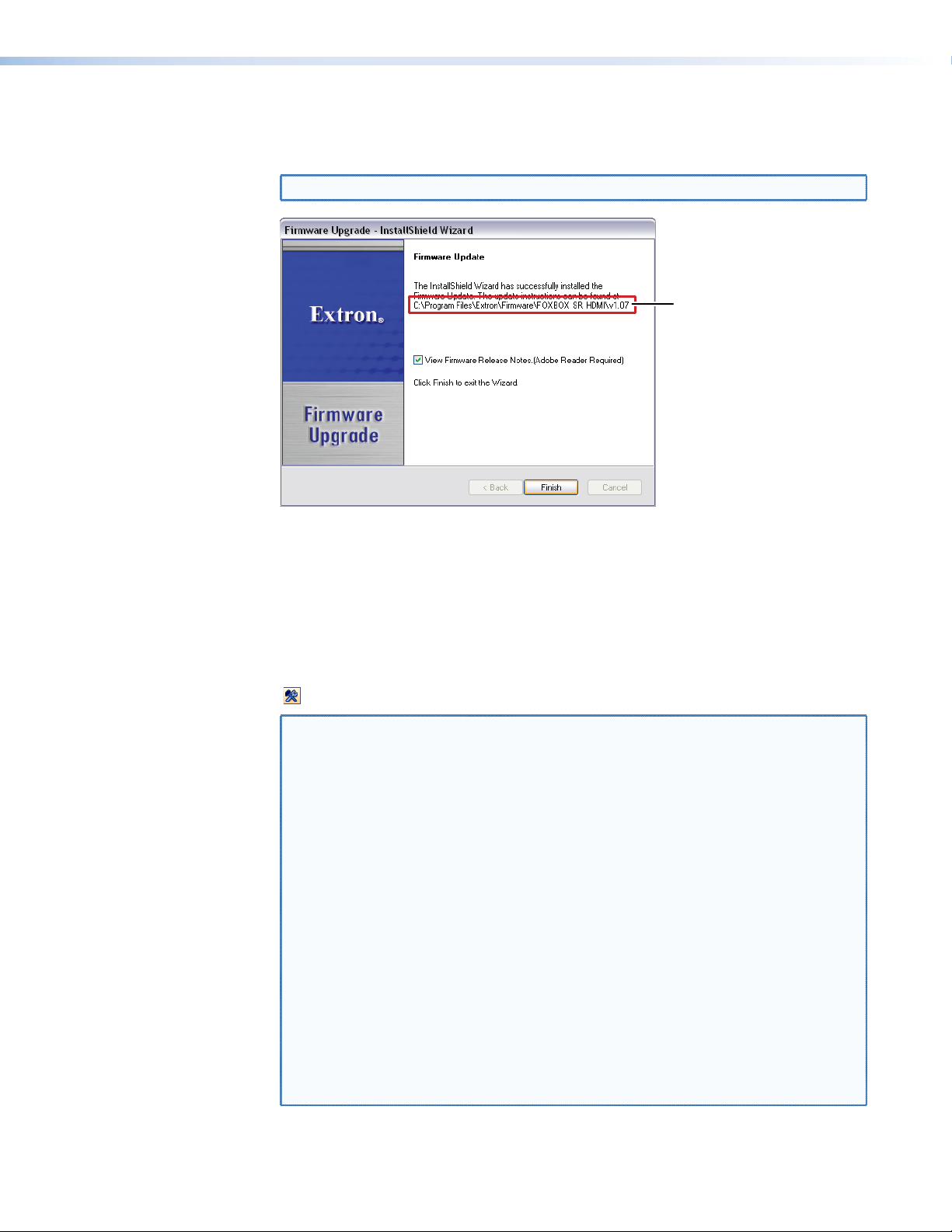
4. Follow the instructions on the rest of the download screens to download the firmware
lder where
update from the Extron website, start the Extron Installation Program to extract the
firmware file, and place it in a folder identified in the program window.
NOTE: Note the folder to which the firmware file is saved (see figure 29).
Fo
firmware is
installed
Figure 29. Location of the Firmware File
Loading the firmware
To load a new version of firmware to your receiver, call the Firmware Loader software from
within the Signal Processing Product Control Program. The serial port on your computer
must be connected to the Configuration port on the unit (see “Front panel Configuration
port“ on page 12 for more information).
1. In the Signal Processing Product Control Program, click the Firmware Loader button
( ) on the tool bar.
NOTE: If the Firmware Loader button does not appear on the tool bar, the Firmware
Loader software is not installed. Install it as follows:
a. On the Extron website, click the Download tab.
b. On the Download Center page, click Software on the left sidebar
menu.
c. Locate the “Firmware Loader” line and click the Download link at the far
right.
d. Follow the instructions on the download screens to save the installer file
to your computer.
e. In Windows Explorer or another file browser, locate the Firmware
Loader executable file in the file system on your computer and doubleclick it to open it.
f. Follow the instructions on the Installation Wizard screens to install the
Firmware Loader on your computer. Unless you specify otherwise, the
installer program places the Firmware Loader file, “FWLoader.exe” in
C:\Program Files\Extron\FWLoader.
If the Extron and FWLoader folders do not yet exist in your Program
Files folder, the installer creates them.
FOXBOX SR HDMI • Remote Control 35
Page 44
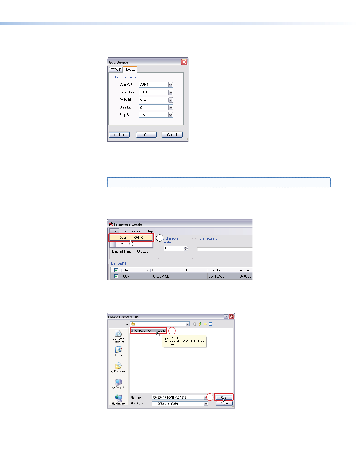
2. If you have not previously updated firmware for the FOXBOX unit, on the Add Device
screen (see figure 30), select the RS-232 tab.
Figure 30. Add Device Screen
If you have previously updated firmware for this model, click
Cancel. The Firmware
Loader window appears. Proceed to step 5.
NOTE: The receiver does not have an Ethernet port. Do not select TCP/IP.
3. From the drop-down menus on the RS-232 screen, select the appropriate Com port
number and baud rate (the default is 9600).
4. Click
OK. The Firmware Loader window appears (see figure 313).
5
Figure 31. Extron Firmware Loader Window
5. Select the FOXBOX receiver and click File > Open. The Choose Firmware File screen
appears (see figure 32).
6
6
Figure 32. Choose Firmware File Window
FOXBOX SR HDMI • Remote Control 36
Page 45
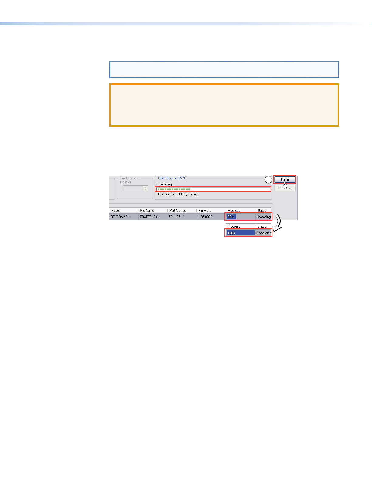
6. Navigate to and select the new firmware file. Click Open. The Choose Firmware File
window closes.
NOTE: When downloaded from the Extron website, the firmware is placed in a
subfolder of C:\Program Files\Extron\Firmware.
ATTENTION:
•
Valid firmware files must have the file extension .S19 Other file types can cause the
unit to stop functioning.
Les fichiers firmware valides doivent contenir l’extension fichier .S19. D’autres types
•
de fichiers peuvent nuire au fonctionnement de l’récepteur.
7. In the Firmware Loader window, click Begin (see figure 33).
The Total Progress and Progress status bars show the progress of the upload. The
firmware upload to the unit may take several minutes. Once the status bars have
progressed from 0% to 100%, and Status is listed as Completed, the firmware loader
utility resets the unit.
7
Figure 33. Firmware Loader Screen
8. Click Exit to close the Firmware Loader.
FOXBOX SR HDMI • Remote Control 37
Page 46

Mounting
This section provides procedures for mounting the transmitter and receiver.
Mounting the Unit
ATTENTION:
•
•
Either of the 1-inch high, quarter-rack width (transmitter) or half-rack width (receiver) units
can be placed on a tabletop, mounted on a rack shelf, or mounted under or through a desk
or other furniture. The receiver can be mounted to a projector bracket.
Tabletop Use
Affix the four included rubber feet to the bottom of the unit and place it in any convenient
location.
Installation and service must be performed by authorized personnel only
L
’installation et l’entretien doivent être effectués par le personnel autorisé uniquement.
.
Mounting kits
Mount the unit using any optional compatible mounting kit listed on the Extron website
(www.extron.com), in accordance with the directions included with the kit. For rack
mounting, see “UL Rack-Mounting Guidelines,” below.
UL Rack-Mounting Guidelines
The following Underwriters Laboratories (UL) requirements pertain to the installation of the
unit into a rack.
• Elevated operating ambient temperature — If installed in a closed or multi-unit rack
assembly, the operating ambient temperature of the rack environment may be greater
than room ambient. Therefore, consider installing the equipment in an environment
compatible with the maximum ambient temperature (TMA = +122 °F, +50 °C) specified
by Extron.
Reduced air flow
•
amount of air flow required for safe operation of the equipment is not compromised.
Mechanical loading
•
hazardous condition is not achieved due to uneven mechanical loading.
Cir
•
•
cuit overloading — Consideration should be given to the connection of the
equipment to the supply circuit and the effect that overloading of the circuits might have
on overcurrent protection and supply wiring. Appropriate consideration of equipment
nameplate ratings should be used when addressing this concern.
Reliable earthing (gr
should be maintained. Particular attention should be given to supply connections other
than direct connections to the branch circuit (such as use of power strips).
— Installation of the equipment in a rack should be such that the
— Mounting of the equipment in the rack should be such that a
ounding) — Reliable earthing of rack-mounted equipment
38FOXBOX SR HDMI • Mounting
Page 47

Extron Warranty
Extron Electronics warrants this product against defects in materials and workmanship for a period of three years
from the date of purchase. In the event of malfunction during the warranty period attributable directly to faulty
workmanship and/or materials, Extron Electronics will, at its option, repair or replace said products or components,
to whatever extent it shall deem necessary to restore said product to proper operating condition, provided that it is
returned within the warranty period, with proof of purchase and description of malfunction to:
USA, Canada, South America,
and Central America:
Extron Electronics
1230 South Lewis Street
Anaheim, CA 92805
U.S.A.
Europe and Africa:
Extron Europe
Hanzeboulevard 10
3825 PH Amersfoort
The Netherlands
Asia:
Extron Asia Pte Ltd
135 Joo Seng Road, #04-01
PM Industrial Bldg.
Singapore 368363
Singapore
This Limited Warranty does not apply if the fault has been caused by misuse, improper handling care, electrical
or mechanical abuse, abnormal operating conditions, or if modifications were made to the product that were not
authorized by Extron.
NOTE: If a product is defective, please call Extron and ask for an Application Engineer to receive an RA (Return
Authorization) number. This will begin the repair process.
USA: 714.491.1500 or 800.633.9876 Europe: 31.33.453.4040
Asia: 65.6383.4400 Japan: 81.3.3511.7655
Japan:
Extron Electronics, Japan
Kyodo Building, 16 Ichibancho
Chiyoda-ku, Tokyo 102-0082
Japan
China:
Extron China
686 Ronghua Road
Songjiang District
Shanghai 201611
China
Middle East:
Extron Middle East
Dubai Airport Free Zone
F13, PO Box 293666
United Arab Emirates, Dubai
Units must be returned insured, with shipping charges prepaid. If not insured, you assume the risk of loss or damage
during shipment. Returned units must include the serial number and a description of the problem, as well as the
name of the person to contact in case there are any questions.
Extron Electronics makes no further warranties either expressed or implied with respect to the product and its quality,
performance, merchantability, or fitness for any particular use. In no event will Extron Electronics be liable for direct,
indirect, or consequential damages resulting from any defect in this product even if Extron Electronics has been
advised of such damage.
Please note that laws vary from state to state and country to country, and that some provisions of this warranty may
not apply to you.
© 2020 Extron Electronics, All Rights Reserved. All trademarks mentioned are the property of their respective owners.
www.extron.com
 Loading...