

Page 1
FOX3 T/R 301
FOX3 T/R 311
Fiber Optic HDMI Transmitters and Receivers
User Guide
Fiber Optic Extenders
68-2711-01 Rev. A
04 20
Page 2
Safety Instructions
Safety Instructions • English
WARNING: This symbol, , when used on the product, is intended
to alert the user of the presence of uninsulated dangerous voltage
within the product’s enclosure that may present a risk of electric
shock.
ATTENTION: This symbol, , when used on the product, is intended
to alert the user of important operating and maintenance (servicing)
instructions in the literature provided with the equipment.
For information on safety guidelines, regulatory compliances, EMI/EMF
compatibility, accessibility, and related topics, see the Extron Safety and
Regulatory Compliance Guide, part number 68-290-01, on the Extron
website, www.extron.com.
Sicherheitsanweisungen • Deutsch
WARNUNG: Dieses Symbol auf dem Produkt soll den Benutzer
darauf aufmerksam machen, dass im Inneren des Gehäuses dieses
Produktes gefährliche Spannungen herrschen, die nicht isoliert sind
und die einen elektrischen Schlag verursachen können.
VORSICHT: Dieses Symbol auf dem Produkt soll dem Benutzer in
der im Lieferumfang enthaltenen Dokumentation besonders wichtige
Hinweise zur Bedienung und Wartung (Instandhaltung) geben.
Weitere Informationen über die Sicherheitsrichtlinien, Produkthandhabung,
EMI/EMF-Kompatibilität, Zugänglichkeit und verwandte Themen finden Sie in
den Extron-Richtlinien für Sicherheit und Handhabung (Artikelnummer
68-290-01) auf der Extron-Website, www.extron.com.
Istruzioni di sicurezza • Italiano
AVVERTENZA: Il simbolo, , se usato sul prodotto, serve ad
avvertire l’utente della presenza di tensione non isolata pericolosa
all’interno del contenitore del prodotto che può costituire un rischio di
scosse elettriche.
ATTENTZIONE: Il simbolo, , se usato sul prodotto, serve ad avvertire
l’utente della presenza di importanti istruzioni di funzionamento e
manutenzione nella documentazione fornita con l’apparecchio.
Per informazioni su parametri di sicurezza, conformità alle normative,
compatibilità EMI/EMF, accessibilità e argomenti simili, fare riferimento
alla Guida alla conformità normativa e di sicurezza di Extron, cod. articolo
68-290-01, sul sito web di Extron, www.extron.com.
I
Instrucciones de seguridad • Español
ADVERTENCIA: Este símbolo, , cuando se utiliza en el producto,
avisa al usuario de la presencia de voltaje peligroso sin aislar dentro
del producto, lo que puede representar un riesgo de descarga
eléctrica.
ATENCIÓN: Este símbolo, , cuando se utiliza en el producto, avisa
al usuario de la presencia de importantes instrucciones de uso y
mantenimiento recogidas en la documentación proporcionada con el
equipo.
Para obtener información sobre directrices de seguridad, cumplimiento
de normativas, compatibilidad electromagnética, accesibilidad y temas
relacionados, consulte la Guía de cumplimiento de normativas y seguridad
de Extron, referencia 68-290-01, en el sitio Web de Extron, www.extron.com.
Instructions de sécurité • Français
AVERTISSEMENT : Ce pictogramme, , lorsqu’il est utilisé sur le
produit, signale à l’utilisateur la présence à l’intérieur du boîtier du
produit d’une tension électrique dangereuse susceptible de provoquer
un choc électrique.
ATTENTION : Ce pictogramme, , lorsqu’il est utilisé sur le produit,
signale à l’utilisateur des instructions d’utilisation ou de maintenance
importantes qui se trouvent dans la documentation fournie avec le
matériel.
Pour en savoir plus sur les règles de sécurité, la conformité à la
réglementation, la compatibilité EMI/EMF, l’accessibilité, et autres sujets
connexes, lisez les informations de sécurité et de conformité Extron, réf.
68-290-01, sur le site Extron, www.extron.com.
Page 3
Copyright
© 2020 Extron Electronics. All rights reserved. www.extron.com
Trademarks
All trademarks mentioned in this guide are the properties of their respective owners.
The following registered trademarks (®), registered service marks (SM), and trademarks (TM) are the property of RGBSystems, Inc. or ExtronElectronics (see the
current list of trademarks on the Terms of Use page at www.extron.com):
Registered Trademarks (
Extron, Cable Cubby, ControlScript, CrossPoint, DTP, eBUS, EDID Manager, EDID Minder, Flat Field, FlexOS, Glitch Free, Global
Configurator, GlobalScripter, GlobalViewer, Hideaway, HyperLane, IPIntercom, IPLink, KeyMinder, LinkLicense, LockIt, MediaLink,
MediaPort, NAV, NetPA, PlenumVault, PoleVault, PowerCage, PURE3, Quantum, ShareLink, Show Me, SoundField, SpeedMount,
SpeedSwitch, StudioStation, SystemINTEGRATOR, TeamWork, TouchLink, V-Lock, VideoLounge, VN-Matrix, VoiceLift, WallVault, WindoWall,
XPA, XTP, XTPSystems, and ZipClip
Registered Service Mark
(SM)
: S3 Service Support Solutions
Trademarks (™
AAP, AFL (Accu-RATEFrameLock), ADSP(Advanced Digital Sync Processing), Auto-Image, AVEdge, CableCover, CDRS(ClassD
Ripple Suppression), Codec Connect, DDSP(Digital Display Sync Processing), DMI (DynamicMotionInterpolation), DriverConfigurator,
DSPConfigurator, DSVP(Digital Sync Validation Processing), eLink, EQIP, Everlast, FastBite, Flex55, FOX, FOXBOX, IP Intercom
HelpDesk, MAAP, MicroDigital, Opti-Torque, PendantConnect, ProDSP, QS-FPC(QuickSwitch Front Panel Controller), RoomAgent,
Scope-Trigger, SIS, SimpleInstructionSet, Skew-Free, SpeedNav, Triple-Action Switching, True4K, True8K, Vector™ 4K, WebShare, XTRA,
and ZipCaddy
®
)
)
Page 4

FCC Class A Notice
This equipment has been tested and found to comply with the limits for a Class A digital
device, pursuant to part15 of the FCC rules. The ClassA limits provide reasonable
protection against harmful interference when the equipment is operated in a commercial
environment. This equipment generates, uses, and can radiate radio frequency energy and,
if not installed and used in accordance with the instruction manual, may cause harmful
interference to radio communications. Operation of this equipment in a residential area is
likely to cause interference. This interference must be corrected at the expense of the user.
Battery Notice
This product contains a battery. Do not open the unit to replace the battery. If the
battery needs replacing, return the entire unit to Extron (for the correct address, see the
Extron Warranty section on the last page of this guide).
CAUTION: Risk of explosion. Do not replace the battery with an incorrect type. Dispose
ATTENTION : Risque d’explosion. Ne pas remplacer la pile par le mauvais type de pile.
of used batteries according to the instructions.
Débarrassez-vous des piles usagées selon le mode d’emploi.
Class 1 Laser Product
Produit laser de classe1
Any service to this product must be carried out by Extron Electronics and its qualified
service personnel.
CAUTION: Using controls, making adjustments, or performing procedures in a manner
other than what is specified herein may result in hazardous radiation exposure.
NOTE: For more information on safety guidelines, regulatory compliances,
EMI/EMF compatibility, accessibility, and related topics, see the “Extron Safety and
Regulatory Compliance Guide” on the Extron website.
Si ce produit a besoin d’un quelconque entretient, celui-ci doit être fait par
ExtronElectronics et son personnel qualifié.
ATTENTION : L’utilisation de commandes, la réalisation de réglages, ou l’exécution de
procédures de manière contraire aux dispositions établies dans le présent document,
présente un risque d’exposition dangereuse aux radiations.
Remarque : Pour plus d'informations sur les directives de sécurité, les conformités de
régulation, la compatibilité EMI/EMF, l'accessibilité, et les sujets en lien, consultez le
«Informations de sécurité et de conformité Extron» sur le site internet d'Extron.
Page 5
Conventions Used in this Guide
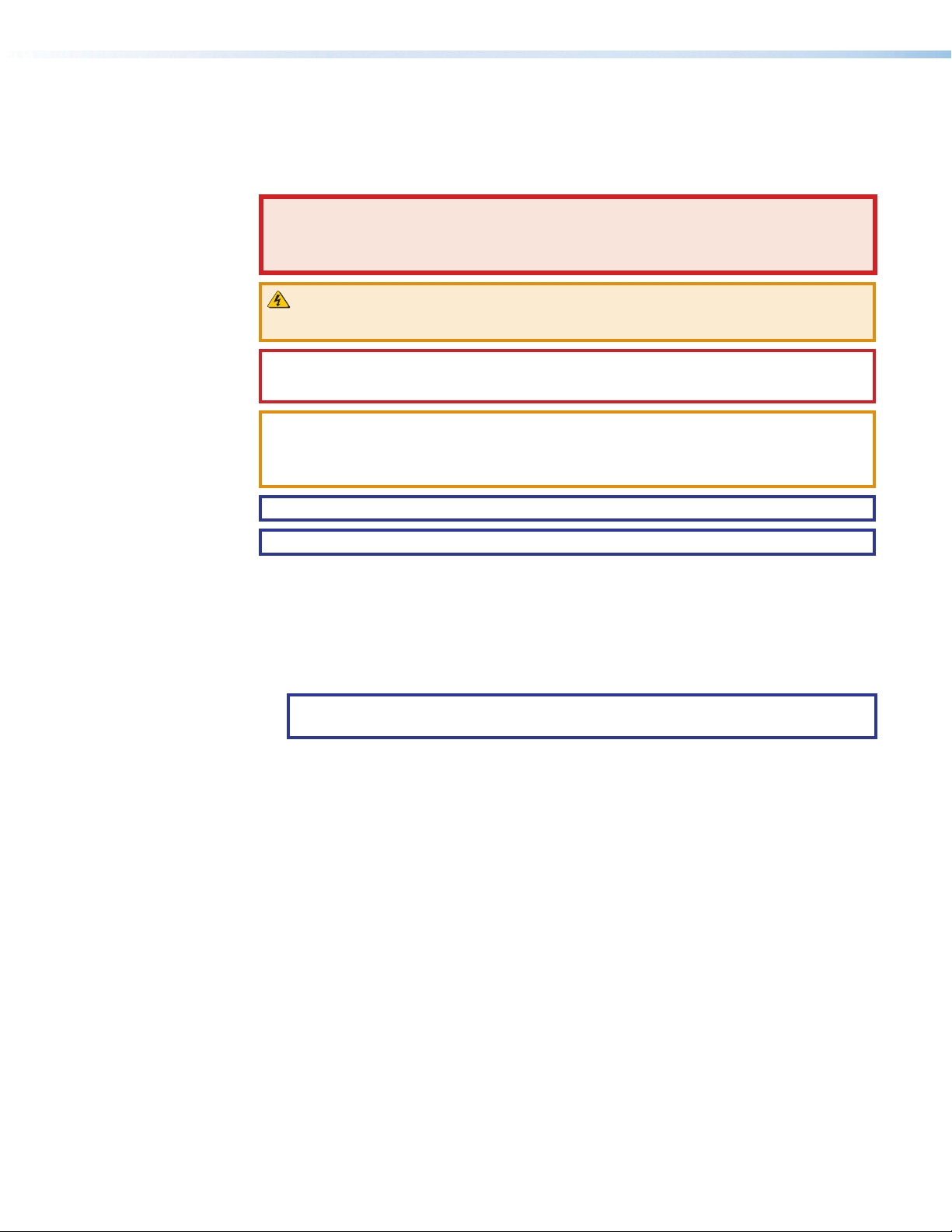
Notifications
The following notifications are used in this guide:
DANGER:
• Will result in serious injury or death.
• Entraînera des blessures graves ou la mort.
WARNING: Potential risk of severe injury or death.
AVERTISSEMENT : Risque potentiel de blessure grave ou de mort.
CAUTION: Risk of minor personal injury.
ATTENTION : Risque de blessuremineure.
ATTENTION:
• Risk of property damage.
• Risque de dommages matériels.
NOTE: A note draws attention to important information.
TIP: A tip provides a suggestion to make working with the application easier.
Software Commands
Specifications Availability
Commands are written in the fonts shown here:
^AR Merge Scene,,0p1 scene 1,1 ^B 51 ^W^C.0
[01] R 0004 00300 00400 00800 00600 [02] 35 [17] [03]
E X! *X1&* X2)* X2#* X2! CE}
NOTE: For commands and examples of computer or device responses used in this
guide, the character “0” is the number zero and “O” is the capital letter “o.”
Computer responses and directory paths that do not have variables are written in the font
shown here:
Reply from 208.132.180.48: bytes=32 times=2ms TTL=32
C:\Program Files\Extron
Variables are written in slanted form as shown here:
ping xxx.xxx.xxx.xxx —t
SOH R Data STX Command ETB ETX
Selectable items, such as menu names, menu options, buttons, tabs, and field names are
written in the font shown here:
From the File menu, select New.
Click the OK button.
Product specifications are available on the Extron website, www.extron.com.
Extron Glossary of Terms
A glossary of terms is available at http://www.extron.com/technology/glossary.aspx.
Page 6

Page 7

Contents
Introduction ................................................1
About this Guide .................................................. 1
Product Description ............................................. 1
Transmitter....................................................... 3
Receiver .......................................................... 3
Both Units ....................................................... 3
System Compatibility ....................................... 3
Fiber Cable Transmission Modes ..................... 4
Extron LinkLicense........................................... 4
Features .............................................................. 4
Installation and Operation............................7
Installation Overview ............................................ 7
Rear Panel Features ............................................ 7
Transmitter Rear Panel Connections ................ 7
Receiver Rear Panel Connections .................. 10
Connector and Cable Details ............................. 13
HDMI Connectors .......................................... 13
Analog Audio Connectors .............................. 14
RS-232, IR, and Sync Connectors ................. 14
TP Cable Termination and
Recommendations ....................................... 15
USB HID and USB 2.0 Connectors ................ 16
Front Panel Features .......................................... 17
Operation .......................................................... 18
Reset ............................................................. 18
Configuration ..................................................... 20
EDID .............................................................. 20
HDCP ............................................................ 20
RS-232 Insertion............................................ 21
Audio Configuration ........................................... 22
Audio Embedding .......................................... 22
Input Audio Gain ............................................ 22
Input Audio .................................................... 22
Output Audio Volume ..................................... 22
Audio Return ................................................. 22
Audio Mute .................................................... 22
SIS Configuration and Control ...................23
Host Control Ports ............................................. 23
Rear Panel RS-232 Port ................................ 23
Front Panel Configuration USB Port ............... 23
Ethernet (LAN) Ports ...................................... 24
Establishing a Connection.............................. 24
Simple Instruction Set Control ........................... 26
Host-to-Unit Instructions ................................ 26
Device-Initiated Power-Up Message .............. 26
Error Responses ............................................ 26
Timeout ......................................................... 27
Using the Command and Response Table ..... 27
Common symbol definitions........................... 28
Command and Response Table for
SIS Commands ................................................ 29
Configuration Software .............................33
Software/Firmware Installation ........................... 33
Connecting to PCS ............................................ 35
Device Discovery Panel .................................. 35
TCP/IP Panel ................................................. 36
Offline Device Preview .................................... 36
Software Overview ............................................. 37
Software Menu .............................................. 38
Device Menu.................................................. 40
Internal Web Page ..................................... 42
Accessing the Internal Web Page ...................... 42
Disabling Compatibility Mode ......................... 43
Web Page Panels .............................................. 43
Device Info Panel ........................................... 43
Device Status Panel ....................................... 44
Network Settings Panel ................................. 45
Firmware Panel .............................................. 45
Roles and Permissions Panel ......................... 46
LinkLicense Panel .......................................... 47
About the FOX3T/R301/311 ........................ 48
viiFOX3 T/R 301/311 Transmitters and Receivers • Contents
Page 8

Equipment Mounting ................................. 49
Mounting the Transmitter ................................... 49
Tabletop Use ................................................. 49
Mounting kits ................................................. 49
UL Rack-Mounting Guidelines ....................... 49
FOX3 T/R 301/311 Transmitters and Receivers • Contents viii
Page 9

Introduction
WARNING: The FOX3T/R301 and FOX3T/R311 output continuous invisible light
(Class 1 rated), which may be harmful to the eyes; use with caution.
AVERTISSEMENT : Le FOX3T/R301 et FOX3T/R311 émet une lumière invisible en
continu (conforme à la classe1) qui peut être dangereux pour les yeux, à utiliser avec
précaution.
• Do not look into the rear panel fiber optic cable connectors or into the fiber optic
cables themselves.
• Ne regardez pas dans les connecteurs de câble fibre optique sur le panneau arrière
ou dans les câbles fibre optique eux-mêmes.
• Plug the attached dust cap into the optical transceiver when the fiber optic cable is
unplugged.
• Branchez la protection contre la poussière dans l’ensemble émetteur/récepteur
lorsque le câble fibre optique est débranché.
About this Guide
Product Description
This guide contains information about the Extron FOX3T/R301 and FOX3T/R311 fiber
optic extenders.
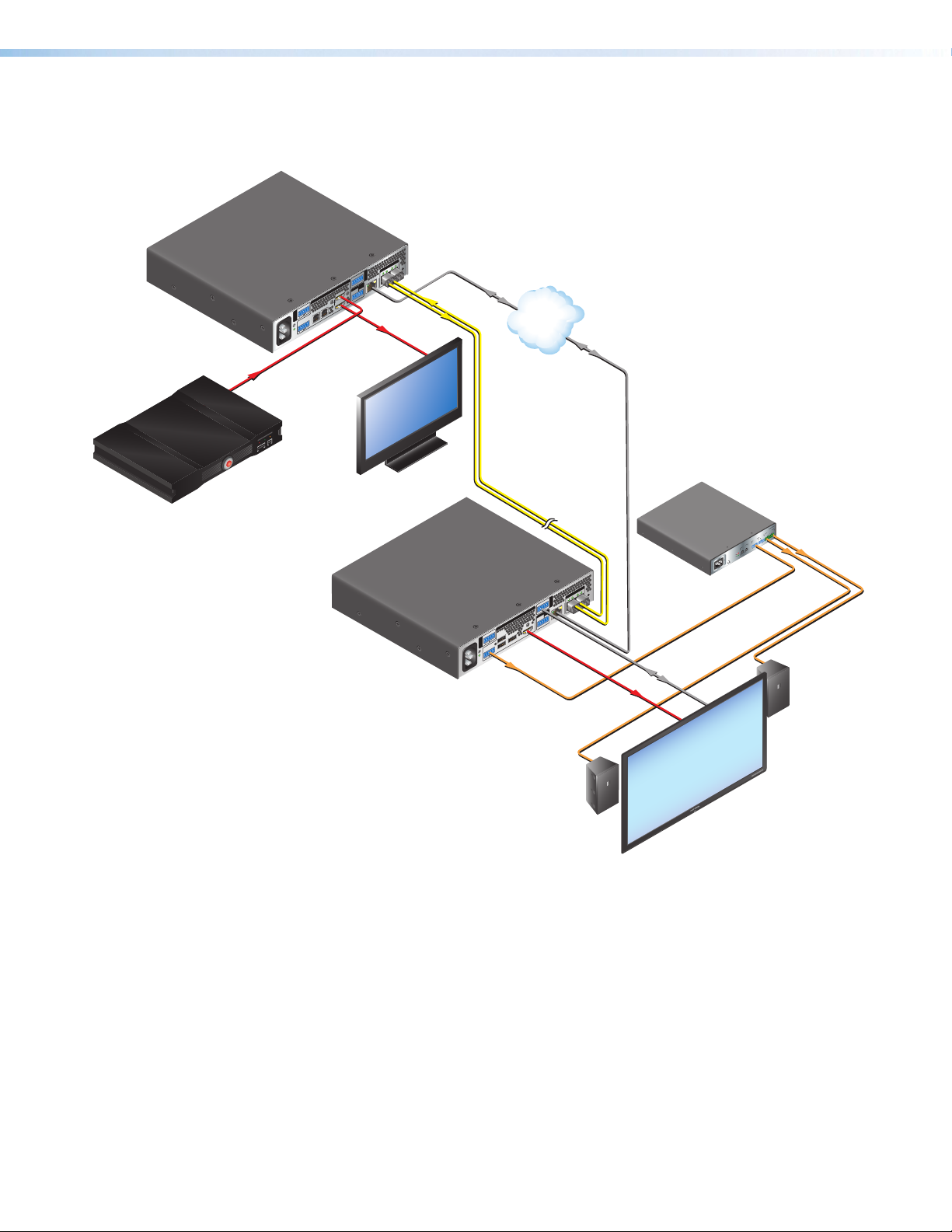
The FOX3T/R301 and FOX3T/R311 Transmitter and Receiver are ultra-high performance
fiber optic extender sets for long haul transmission of the following over two fiber optic
cables (see figure1 on page2):
• Uncompressed or visually lossless HDCP-compliant 4096x2160 or 3840x2160 (UHD)
@60Hz video HDMI video
• 2-CH LPCM audio
• RS-232 and IR control signals
• USB HID (for Human Interface Devices such as keyboards and mice
• USB 2.0 (FOX3T/R301 transmitter and receiver only)
• 3D Sync
The transmitter and receiver extend HDMI signals up to:
• 20 km (12.4 miles) for the singlemode cables
• 500 m (1640 feet) with 50 µm OM4 4700 MHz bandwidth laser optimized multimode
cables
(see Fiber Cable Transmission Modes on page4).
FOX3 T/R 301/311 Transmitters and Receivers • Introduction 1
Page 10
FOX3 T/R 301/311 Transmitters and Receivers • Introduction
Extron
FOX3 T 301
Fiber Optic Transmitter
RS-232
Tx
REMOTE
RS-232
INPUTS
HDMI
Tx
LOOP OUT
R
USB 2.0
L
USB HID
0.7A MAX
RETURN
AUDIO
~
HOST
R
AUDIO
100-240V
HOST
L
60-60 Hz
HDMI Input
IR
CONTROL
LAN
TxRxG
Rx
3D
SYNC
5VG
Rx S
HDMI
Loop out
B
R
OUTPUTS
A
OUT IN
IN
OUT
FOX3 T 301
Ethernet
LAN
4K Media Player
STATUS
PLAY
POWER
USB
SD CARD
Local
Monitor
Up to 20 km (12.43 miles)
Singlemode Fiber
SM Model
Extron
XPA 1002
Power Amplier
4K
CLASS 2 WI
E
OT
M
E
R
A
m
E
0
5
UT
M
OL/
10V
V
UTS
NP
I
Y
2
DB
N
A
T
S
1
L
E
LEV
2
1
0
2
1
0
/
R
TE
I
M
I
ECT
L
Hz
0
-6
OT
0
5
R
P
A,
.3
1
GNAL
SI
V
0
4
2
0
0
1
B
R
INPUTS
A
R
I
IN
CONTROL
RS-232
OUT
A MAX
0.7
~
-240V
100
Extron
60-60 Hz
FOX3 R 301
Fiber Optic Receiver
LAN
IN
TxRxG
OUT
3D
TxRx
FOX3 R 301
SYNC
REMOTE
RS-232
OUTPUTS
5VG
S
TxRx
R
DEVICES
HDMI
L
USB 2.0
USB HID
1
1
RETURN
500 mA
AUDIO
2
R
AUDIO
100 mA
L
Audio
Output
HDMI
Output
Ethernet
80
L
MODE
RS-232
Extron
SI 28
Surface-mount
Speakers
4K Display
Figure 1. Typical FOX3T/R301 Transmitter and Receiver Application
PA 1002
X
G
UT
N
P
RI
2
OUT
1
2
Page 11

FOX3 T/R 301/311 Transmitters and Receivers • Introduction
Transmitter
The FOX3T301 and FOX3 T 311 transmitters accept HDMI video, at a resolution of up
to 4K (4096x2160 @ 60 Hz). The video input can also include embedded audio. The
transmitter also loops the HDMI input through for a local monitor.
The transmitter can accept an analog audio input on a 5-pole captive screw connector. The
transmitter automatically detects whether embedded audio is present on the HDMI input. If
none is detected, the transmitter selects the analog audio for the unit to embed in the digital
video stream and transmit to the receiver. Audio can be selected via an Simple Instruction
Set (SIS) command or Product Configuration Software (PCS).
The transmitter has an HID USB port (both models) and a USB 2.0 port (FOX3T301)
that connects directly to USB ports on a PC or USB host. The transmitter includes USB
peripheral emulation to enable trouble-free booting of a host computer that is not connected
to a keyboard or mouse.
It also accepts a 3D sync signal.
The transmitter can receive an optional return (receiver-to-transmitter) stream of serial
RS-232 communications from a controlled device, such as projector responses.
The transmitter converts the HDMI video, the selected audio, and the RS-232 serial
communication, one or both USB inputs, and 3D sync into two proprietary data streams
and outputs them as optical signals via fiber optic small form factor pluggable (SFP)
modules on two LC connector to a compatible Extron FOX3 fiber optic receiver. It also can
receive an audio return channel.
The transmitter has a built-in color bars test pattern to assist in setting up the display
equipment.
Receiver
The FOX3R301 and FOX3 R 311 receivers accept proprietary optical signals on one, two,
or up to three LC connectors from a compatible fiber optic FOX3 transmitter. The receiver is
compatible with all Extron FOX3 transmitters.
The receiver outputs HDMI video, digital audio (embedded in the HDMI output), analog
audio, RS-232 and IR commands and data, USB signals, and 3D sync.
The receiver has two HID USB ports (both models) to connect one or two peripheral devices
and a USB 2.0 port (FOX3R301) that connects directly to USB devices.
If the receiver is appropriately configured and has return fiber optic cables installed, it also
can receive RS-232, IR, and USB returns from controlled devices and send them to the
transmitter via a proprietary optical signal.
The video output of the receiver is a lossless HDMI image up to 4K (4096x2160 @ 60 Hz),
including 1080p/60 Hz with Deep Color.
Both Units
The transmitter and receiver have many controls, including audio adjustments, that are
available under Remote RS-232 and USB port Simple Set Instruction (SIS) control and PCS.
Both units have video, audio, fiber light status, and lost-light alarm indicators.
System Compatibility
NOTE: The FOX3 products are not compatible with legacy FOX, FOXBOX, FOX II,
PowerCage 401 FOX, or PowerCage 1600 FOX products.
3
Page 12

FOX3 T/R 301/311 Transmitters and Receivers • Introduction
Fiber Cable Transmission Modes
The transmitter and receiver are further categorized by the type of fiber optic cable,
multimode or singlemode, which define the effective range of transmission:
Multimode — Long distance, up to 500 m (1640 feet) (depending on the fiber cable)
Singlemode — Very long distance, up to 20 km (12.4 miles)
NOTE: The multimode and singlemode units are physically and functionally identical,
with the exception of the effective range of transmission. In this guide, any reference
applies to either transmission mode unless otherwise specified.
Extron LinkLicense
An Extron LinkLicense unlocks features that add convenience, expand system options, and
enhance the capabilities of Extron products. Each LinkLicense can be purchased separately
from the FOX3 device and activated as the need arises.
LinkLicense upgrades available for the FOX3 transmitter and receiver include the following:
• Uncompressed Video Upgrade —
• This LinkLicense is enabled once and lasts for the life of the product.
• Allows the FOX3 devices to pass uncompressed 4K @ 60 Hz video on the second
SFP module, enabling the highest video performance.
Features
• FOX3 T 301 — Transmits HDMI video, USB HID, USB 2.0, stereo audio, RS-232
control, IR control, and 3D sync signals over fiber optic cabling.
• FOX3 T 311 — Transmits HDMI video, USB HID, stereo audio, RS-232 control, IR
control, and 3D sync signals over fiber optic cabling.
• FOX3 R 301 — Receives HDMI video, USB HID, USB 2.0, stereo audio, RS-232
control, IR control, and 3D sync signals over fiber optic cabling.
• FOX3 R 311 — Receives HDMI video, USB HID, stereo audio, RS-232 control, IR
control, and 3D sync signals over fiber optic cabling.
• Supports mathematically lossless 4K video up to 4096x2160 @ 60 Hz with 4:4:4
chroma sampling over one fiber.
• Supports uncompressed 4K video up to 4096x2160 @ 60 Hz with 4:4:4 chroma
sampling over two fibers.
• Supported HDMI 2.0 specification features include data rates up to 18 Gbps,
Deep Color up to 12 bit, and 3D.
• HDCP 2.
• Device class filtering on USB HID port restricts the range of device types
to HID — Device class filtering prevents unauthorized downloading or uploading of
content via the USB port in secure environments. The USB HID port is configured at the
factory, such that device class filtering cannot be removed or altered in the field.
• Supports USB 2.0 to 1.0 devices and USB 3.0 devices that can operate at USB
2.0 data rates of up to 480 Mbps (FOX3 T/R 301) — Provides USB extension,
allowing connection to peripheral devices over the same fiber optic cable as video and
audio.
• Buffered HDMI input loop-out (FOX3 transmitters) — Local HDMI output provides
signals for a local display, enabling monitoring or sharing of content without the need for
a separate distribution amplifier.
3 compliant
4
Page 13

FOX3 T/R 301/311 Transmitters and Receivers • Introduction
• HDMI audio de-embedding with analog stereo outputs (FOX3 receivers) —
Digital HDMI audio is made available as a balanced or unbalanced analog stereo signal
on captive screw connectors.
• Key Minder continuously verifies HDCP compliance for quick, reliable
switching — Authenticates and maintains continuous HDCP encryption between
input and output devices to ensure quick and reliable switching in professional AV
environments.
• EDID Minder automatically manages EDID communication between connected
devices (FOX3 transmitters) — EDID Minder ensures that all sources power up
properly and reliably output content for display.
• Audio gain and attenuation adjustment capability (FOX3 transmitters) — Setting
the level of gain or attenuation eliminates noticeable volume differences when switching
between sources.
• Audio embedding (FOX3 transmitters) — Analog stereo audio signals are converted
to digital HDMI audio.
• Analog audio return channel — Provides balanced return analog stereo audio input
to support a remote audio source at the receiver.
• Bidirectional RS-232 and IR signal transmission over fiber optic cabling for AV
device control — Bidirectional RS-232 and IR control pass-through enables a remote
display to be controlled without the need for additional cabling. Two fibers are required
for bidirectional communications.
• User-selectable HDCP authorization (FOX3 transmitters) — Allows the transmitter
to appear HDCP compliant or non HDCP compliant to the connected source.
• HDCP Visual Confirmation (FOX3 receivers) — When HDCP encrypted content is
transmitted to a non HDCP compliant display, a full screen green signal is sent to the
display for immediate visual confirmation that protected content cannot be viewed on
that display.
• Integrated two-port HID hub with 100mA available on each port (FOX3
receivers) — Allows simultaneous connection to multiple peripheral devices, including
keyboards, mice, and other HID - Human Interactive Devices.
• Host emulation on the USB HID ports (FOX3 receivers) — Offers increased system
reliability by emulating a continuous connection between the HID-compliant keyboard
and mouse and a host.
• Peripheral emulation on USB HID port (FOX3 transmitters) — Offers increased
system reliability by emulating a continuous connection between the host and an HIDcompliant keyboard and mouse.
• LinkLicense Support — Extron LinkLicense unlocks features that add convenience,
expand system functionality, and enhance the capabilities of Extron products.
• Front panel USB configuration port — Enables easy system configuration and
firmware upgrading without having to access the rear panel.
• Ethernet monitoring and control — Enables control and proactive monitoring over a
LAN, WAN, or the Internet.
• RS-232 control — Features an RS-232 serial port for control and configuration.
• Real-time status LED indicators for troubleshooting and monitoring — Front and
rear panel LEDs verify signal presence, HDCP authentication, fiber link status, audio,
USB HID, USB 2.0, and power.
• Easy setup and commissioning with Extron PCS - Product Configuration
Software — Conveniently configures multiple products using a single software
application.
5
Page 14

FOX3 T/R 301/311 Transmitters and Receivers • Introduction
• Internal color bars test pattern for calibration and setup — Simplifies setup and
installation by providing a video signal when a source is unavailable.
• Compatible with Extron FOX3 Series matrix switchers — Creates HDCP-
compliant signal distribution systems.
• JITC Certified — Successfully completed interoperability and information assurance
testing for use in government applications and other mission-critical environments.
• Industry standard LC connectors provide reliable physical connectivity and
precise fiber core alignment
• Available as an 850 nm multimode model for moderate-range transmissions up
to 500 m (1640 feet) and a 1310 nm singlemode model for extreme distances up
to 20 km (12.4 miles).
• 1U high, half rack width metal enclosure
• Internal Extron Everlast power supply — Provides worldwide power compatibility,
with high demonstrated reliability and low power consumption for reduced operating
cost.
• Extron Everlast Power Supply is covered by a 7-year parts and labor warranty
6
Page 15
Installation and
F
G
Operation
This section details the installation of the FOX3T/R301/311 transmitter and receiver
system, including:
• Installation Overview
• Rear Panel Features
• Front Panel Features
• Connector and Cable Details
• Operation
Installation Overview
Follow these steps to install and set up an Extron FOX3T/R301/311 transmitter and
receiver system for operation:
Turn off all of the equipment. Ensure that the video source and the output display are all
c
turned off and disconnected from the power source.
Mount the transmitter and receiver (see Equipment Mounting on page49).
c
Connect the cables and configure the units (see “Transmitter Rear Panel Connections,”
c
starting below).
Plug in the power supplies, then turn on the display and the input.
c
Rear Panel Features
Transmitter Rear Panel Connections
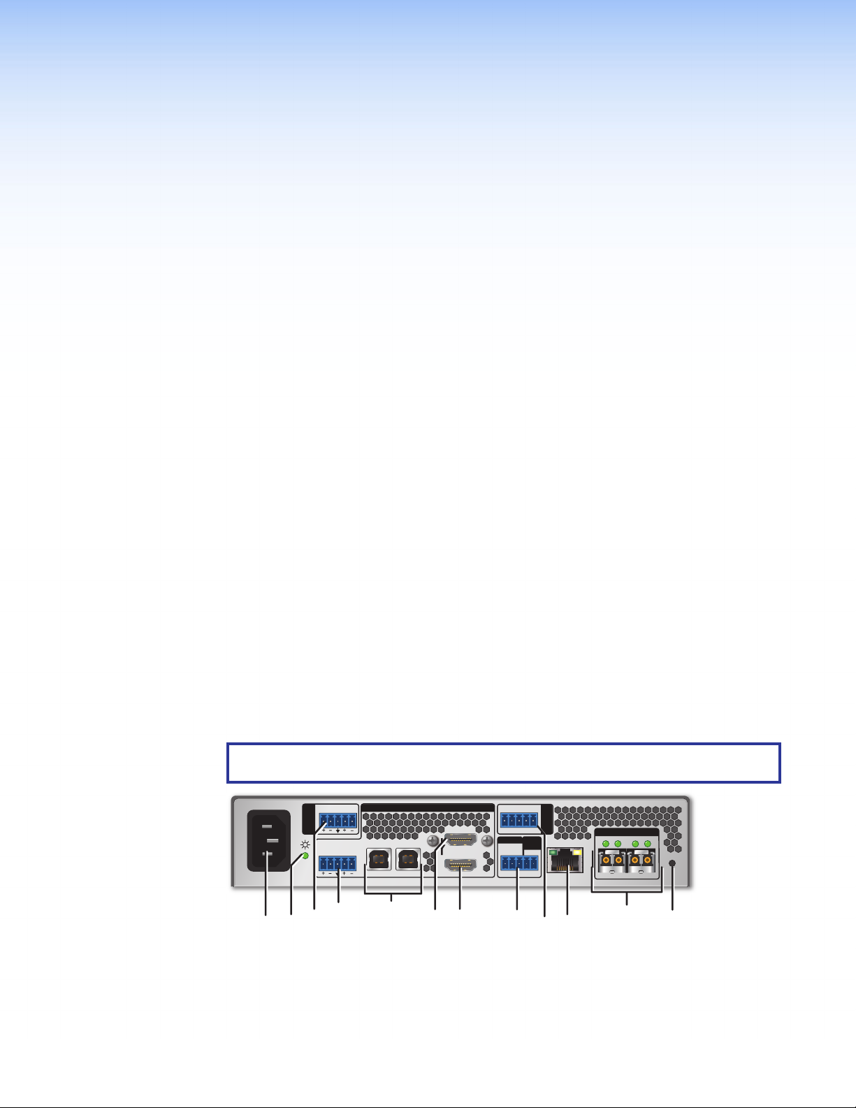
NOTE: Figure 2 shows the FOX3T301 transmitter. The FOX3 T 311 looks similar, with
the exception of the USB ports (E). It does not have the USB 2.0 port.
0.7A MAX
100-240V
Power inlet
A
Power LED
B
Audio Return
C
~
60-60 Hz
Figure 2. FOX3T301 Transmitter Rear Panel Connectors
Audio input
D
USB Host ports
E
HDMI input
F
LR
AUDIO
RETURN
USB HID
AUDIO
LR
CCC HHH
USB 2.0
HOST HOST
J
EEE LLLKKKJJJBBBAAA DDD
G
H
I
FOX3 T/R 301/311 Transmitters and Receivers • Installation and Operation 7
INPUTS
F
F
HDMI
LOOP OUT
G
G
RS-232
Tx Rx Tx RxG
REMOTE
RS-232
Tx Rx S5VG
IR
SYNC
CONTROL
3D
LAN
III
HDMI Loop Out
Remote RS-232/3D Sync port
Control RS-232/IR port
FOX3 T 301
OUTPUTS
A
B
OUTRIN
OUTIN
LAN Ethernet port
J
SFP module and LEDs
K
Reset button
L
Page 16

Power inlet (see figure2 on page7) — Plug a standard IEC power cord into this
A
connector to connect the unit to a 100 VAC to 240 VAC, 50-60 Hz power source.
Power LED — The lit LED indicates power is applied and device is ready to transmit.
B
Audio Return — Connect an audio device, such as an amplifier or powered speakers
C
to this 5-pole, 3.5 mm captive screw connector. This connector outputs returned,
unamplified, line level audio from the receiver (see Analog Audio Connectors on
page14 to wire this connector).
Audio input — This 3.5 mm, 5-pole captive screw connector accepts balanced or
D
unbalanced line level analog audio input that can be transmitted to the receiver (see
Analog Audio Connectors to wire this connector).
USB Host ports — (see USB HID and USB 2.0 Connectors on page16)
E
• USB HID — Connect USB type A to B cables between this USB type B port and
the USB port of a host. The USB HID ports are used only for a mouse or keyboard.
• USB 2.0 (FOX3T301 only) — Connect USB type A to B cables between this USB
type B port and the USB port of a host. The USB 2.0 ports are used for thumb
drives, cameras, keyboards, a mouse, CAC reader, and such devices.
HDMI input — Connect a digital video input to this HDMI port. The transmitter
F
also accepts embedded digital audio on this connector (see HDMI Connectors on
page13 to use the included Extron Lock-It Lacing Bracket).
HDMI Loop Out — If desired, connect a local monitor to this HDMI port.
G
Remote RS-232/3D Sync port —
H
• Remote RS-232 port — For serial control of the transmitter, connect a host
device, such as a computer or touch panel control, via the three left poles
(Tx, Rx, and G) of this 5-pole captive screw connector (see RS-232, IR, and Sync
Connectors on page14 to wire this connector).
• 3D Sync port — For stereoscopic 3D sync, such as external IR emitter for glasses,
connect a PC to the two right poles of the REMOTE RS-232/3D Sync 5-pole
captive screw port on the transmitter (see RS-232, IR, and Sync Connectors to
wire this connector).
Control RS-232 and IR port — Connect a serial RS-232 signal, a modulated or
I
unmodulated IR signal, or both to this 3.5 mm, 5-pole captive screw connector for
bidirectional RS-232 and IR communication (see RS-232, IR, and Sync Connectors
to wire the connector).
NOTES:
• To receive responses from the controlled device over RS-232 or IR, two fiber
optic cables must be connected.
• The FOX3 system can pass RS-232 commands and responses at rates up to
115200 baud.
• RS-232 and IR can be active simultaneously.
LAN Ethernet port — Connect the transmitter to an Ethernet LAN or WAN via this
J
RJ-45 port. Ethernet control allows the operator to configure the transmitter from a
remote location. When connected to an Ethernet LAN or WAN, the transmitter can be
accessed and operated from a computer running a standard Internet browser (see TP
Cable Termination and Recommendations on page15 to wire the connector).
• Link (green) LED — Indicates that the unit is properly connected to an Ethernet
LAN. This LED should light steadily.
• Act (yellow) LED — Indicates transmission of data packets on the RJ-45
connector. This LED should blink as the unit communicates.
NOTE: This is not a pass-through LAN connection
FOX3 T/R 301/311 Transmitters and Receivers • Installation and Operation 8
Page 17
SFP module and LEDs — (see figure2 on page7)
T
K
WARNING: The units output continuous invisible light (Class 1 rated), which may be
harmful to the eyes; use with caution. Plug the attached dust cap into the optical
transceiver when the fiber optic cable is unplugged.
AVERTISSEMENT : Le produit émet une lumière invisible en continu (conforme
à la classe1) qui peut être dangereux pour les yeux, à utiliser avec précaution
Branchez la protection contre la poussière dans l’ensemble émetteur/récepteur
lorsque le câble fibre optique est débranché.
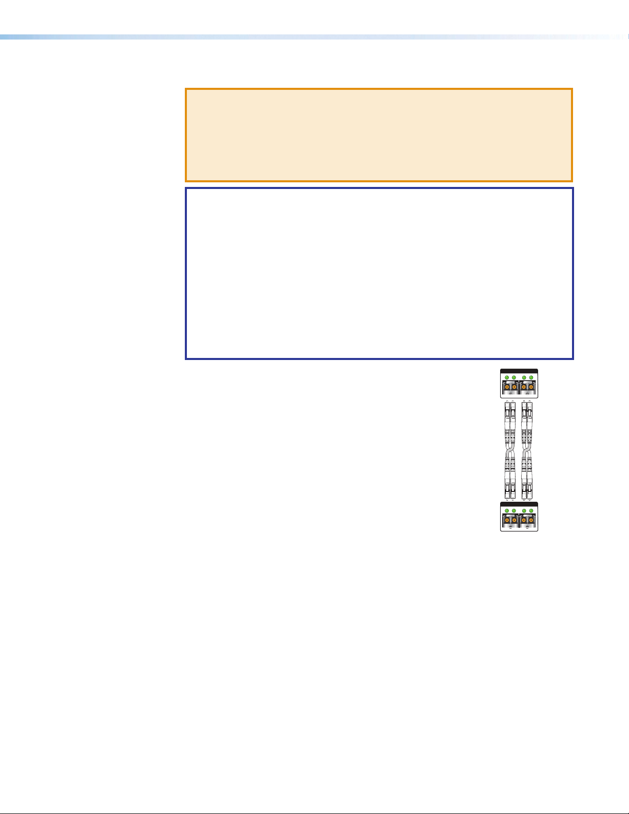
NOTES:
• Ensure the proper fiber cables for the transmitter and receiver pair are used.
Typically, singlemode fiber has a yellow jacket and multimode cable has an
orange or aqua jacket.
• See figure3 for fiber cable connections. Connect the transmitter to a receiver in
one of three ways:
• One way (transmitter to receiver) only, connect transmitter Outputs A (1) to
receiver Inputs A (1).
• Two way (transmitter to receiver and return), connect transmitter Outputs
A (1) to receiver Inputs A (1) and connect transmitter Outputs A (2) to
receiver Inputs A (2).
• Output B is available to transmit a 4K @ 60 Hz uncompressed signal when
the FOX3 4K @ 60 Hz Uncompressed Video LinkLicense is purchased.
OUTPUTS
B
Port A Out (required) — For all one-way video, audio,
1
and serial communications from the transmitter to the
receiver, connect a fiber optic cable to the Out LC port.
Connect the opposite end of this fiber optic cable to
ransmitter
A
OUTIN
112222
OUTIN
the Port A In LC port on the receiver (see figure4, J
on page10) or to any other compatible Extron FOX3
device.
Port A In (optional) — For one-way return audio, USB,
2
and serial communications from the receiver to the
transmitter, connect a fiber optic cable to the In LC port.
Connect the opposite end of this fiber optic cable to the
Port A Out LC port on a receiver (see figure4, J) or to
Receiver
OUTIN
11
INPUTS
B
A
OUTIN
any other compatible Extron FOX3 device.
SFP Link LEDs —
Figure 3. Connection
• Transmit Optical OUT LED lights solid green when powered and lights off when
there is no power on the endpoint.
• Receive Optical IN LED lights solid green when light is present and lights off when
there is no power or light present.
Reset button — Initiates three levels of resets (1, 4, and 5). Use a pointed stylus,
L
ballpoint pen, or small screwdriver to access the recessed button (see Reset on
page18 for detailed reset information).
FOX3 T/R 301/311 Transmitters and Receivers • Installation and Operation 9
Page 18
Receiver Rear Panel Connections
J
EEE KKKJJJIIIBBBAAA DDD HHHCCC FFF GGG
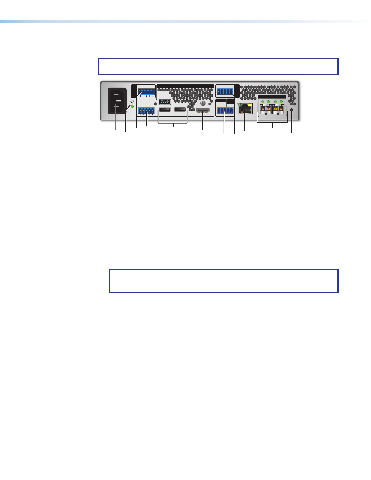
NOTE: Figure 4 shows the FOX3R301 receiver. The FOX3 R 311 looks similar, with the
exception of the USB ports (H). It has no USB 2.0 port.
0.7A MAX
100-240V
~
60-60 Hz
Figure 4. FOX3R301 Receiver Rear Panel Connectors
AUDIO
RETURN
LR
AUDIO
LR
DEVICES
USB HID
1
2
100 mA
1
OUTPUTS
USB 2.0
500 mA
HDMI
RS-232
Tx Rx Tx RxG
REMOTE
RS-232
Tx Rx S5VG
IR
SYNC
CONTROL
3D
LAN
INPUTS
B
A
OUTRIN
OUTIN
FOX3 R 301
Power inlet
A
Power LED
B
Audio Return
C
Audio output
D
Power inlet — Plug a standard IEC power cord into this connector to connect the unit
A
USB Hub ports
E
HDMI output
F
Remote RS-232/3D Sync port
G
Control RS-232/IR port
H
LAN Ethernet port
I
SFP module and LEDs
J
Reset button
K
to a 100 VAC to 240 VAC, 50-60 Hz power source.
Power LED — The lit LED indicates power is applied.
B
Audio Return — Connect a balanced or unbalanced audio input to this 3.5 mm,
C
5-pole captive screw connector for return to the transmitter (see Analog Audio
Connectors on page14 to wire this connector).
Audio output — This 5-pole, 3.5 mm captive screw connector outputs the transmitted,
D
unamplified, line level analog audio (see Analog Audio Connectors to wire this
connector).
NOTE: If embedded digital audio is present on the HDMI output, these analog audio
connectors do not output audio unless forced to so by an SIS command (see
E
Input audio selection on page31).
USB Hub ports — (see USB HID and USB 2.0 Connectors on page16)
• USB HID — Connect USB type A to B cables between this USB type B port
and the USB port of a device. The USB HID ports are used only for a mouse or
keyboard.
• USB 2.0 (FOX3R301 only) — Connect USB type A to B cables between this USB
type B port and the USB port of a device. The USB 2.0 ports are used for thumb
drives, cameras, keyboards, a mouse, CAC reader, and such devices.
HDMI output — Connect a video display to this HDMI output port with a maximum
F
resolution of 4096x2160 @ 60 Hz, 8-bit, 4:4:4 chroma sampling (see HDMI
Connectors on page13 to use the included Extron Lock-It Lacing Bracket).
FOX3 T/R 301/311 Transmitters and Receivers • Installation and Operation 10
Page 19

Remote RS-232/3D Sync port — (see figure4 on page10)
G
• Remote RS-232 port — For serial control of the receiver, connect a host device,
such as a computer or touch panel control, via the three left poles (Tx, Rx, and G)
of this 5-pole captive screw connector (see RS-232, IR, and Sync Connectors on
page14 to wire this connector).
• 3D Sync port — For stereoscopic 3D sync, such as external IR emitter for glasses,
connect a PC to the two right poles of the REMOTE RS-232/3D Sync 5-pole
captive screw port on the receiver (see RS-232, IR, and Sync Connectors to wire
this connector).
Control RS-232/IR port — Connect a serial RS-232 signal, a modulated or
H
unmodulated IR signal, or both to this 3.5 mm, 5-pole captive screw connector for
bidirectional RS-232 and IR communication (see RS-232, IR, and Sync Connectors
on page14 to wire the connector).
NOTES:
• If only one fiber optic cable is connected (see figure5 on page12),
RS-232 or IR reports from the controlled device cannot be recieved. To
receive responses from the controlled device, two fiber optic cables must be
connected.
• The transmitter can pass RS-232 commands and responses at rates up to
115200 baud.
LAN Ethernet port — If desired, connect the receiver to an Ethernet LAN or WAN via
I
this RJ-45 connector. Ethernet control allows the operator to control the receiver from
a remote location. When connected to an Ethernet LAN or WAN, the receiver can be
accessed and operated from a computer running a standard Internet browser (see TP
Cable Termination and Recommendations on page15 to wire the connector).
• Link (green) LED — Indicates that the unit is properly connected to an Ethernet
LAN. This LED should light steadily.
• Act (yellow) LED — Indicates transmission of data packets on the RJ-45
connector. This LED should blink as the unit communicates.
FOX3 T/R 301/311 Transmitters and Receivers • Installation and Operation 11
Page 20

SFP module and LEDs —
T
J
WARNING: The devices output continuous invisible light (Class 1 rated), which
may be harmful to the eyes; use with caution. Plug the attached dust cap into the
optical transceiver when the fiber optic cable is unplugged.
AVERTISSEMENT : Le produit émet une lumière invisible en continu (conforme
à la classe1) qui peut être dangereux pour les yeux, à utiliser avec précaution
Branchez la protection contre la poussière dans l’ensemble émetteur/récepteur
lorsque le câble fibre optique est débranché.
NOTES:
• Ensure the proper fiber cables for the transmitter and receiver pair are used.
Typically, singlemode fiber has a yellow jacket and multimode cable has an
orange or aqua jacket.
• See figure5 for fiber cable connections. Connect the transmitter to a receiver in
one of three ways:
• One way (transmitter to receiver) only, connect transmitter Outputs A (1) to
receiver Inputs A (1).
• Two way (transmitter to receiver and return), connect transmitter Outputs
A (1) to receiver Inputs A (1) and connect transmitter Outputs A (2) to
receiver Inputs A (2).
• Output B is available to transmit a 4K @ 60 Hz uncompressed signal when
the FOX3 4K @ 60 Hz Uncompressed Video LinkLicense is purchased.
OUTPUTS
B
Port A Out (required) — For all one-way video, audio,
1
and serial communications from the transmitter to the
receiver, connect a fiber optic cable to the Out LC port.
Connect the opposite end of this fiber optic cable to
ransmitter
A
OUTIN
112222
OUTIN
the Port A In LC port on the receiver (see figure4, J
on page10) or to any other compatible Extron FOX3
device.
Port A In (optional) — For one-way return audio, USB,
2
and serial communications from the receiver to the
transmitter, connect a fiber optic cable to the In LC port.
Connect the opposite end of this fiber optic cable to the
Port A Out LC port on a receiver (see figure4, J) or to
Receiver
OUTIN
11
INPUTS
B
A
OUTIN
any other compatible Extron FOX3 device.
• Transmit Optical OUT LED lights solid green when
powered and lights off when there is no power on the
endpoint.
Figure 5. Fiber
Cable
Connection
• Receive Optical IN LED lights solid green when light is
present and lights off when there is no power or light
present.
Reset button (see figure4 on page10) — Initiates three levels of resets (1, 4, and
K
5). Use a pointed stylus, ballpoint pen, or small screwdriver to access the recessed
button (see Reset on page18 for detailed reset information).
FOX3 T/R 301/311 Transmitters and Receivers • Installation and Operation 12
Page 21

Connector and Cable Details
33
11
HDMI Connectors
HDMI signals run at a very high frequency and are especially prone to errors caused by bad
video connections, too many adapters, or excessive cable length. To avoid the loss of an
image or jitter, follow these guidelines:
• Limit or avoid the use of adapters.
• Use only cables specifically intended for HDMI or DVI signals.
To securely fasten an HDMI cable to a device:
1. Plug the HDMI cable into the panel connection (see figure6, 1).
44
3
22
55
Figure 6. Installing the LockIt Lacing Bracket
2. Loosen the HDMI connection mounting screw from the panel enough to allow the
LockIt lacing bracket to be placed over it (2). The screw does not have to be removed.
3. Place the LockIt lacing bracket on the screw and against the HDMI connector, then
tighten the screw to secure the bracket (3).
ATTENTION:
• Do not overtighten the HDMI connector mounting screw. The shield to which it
fastens is very thin and can easily be stripped.
4. Loosely place the included tie wrap around the HDMI connector and the LockIt lacing
5. While holding the connector securely against the lacing bracket, use pliers or similar
• Ne serrez pas trop la vis de montage du connecteur HDMI. Le blindage auquel
elle est attachée est très fin et peut facilement être dénudé.
bracket (4).
tools to tighten the tie wrap, then remove any excess length (5).
FOX3 T/R 301/311 Transmitters and Receivers • Installation and Operation 13
Page 22

Analog Audio Connectors
Unbalanced Stereo Output Balanced Stereo Output
IR Device
vice
See figure7 to wire connectors for the appropriate input and output type for the analog
audio and audio return audio. Connectors are included with the transmitter and receiver,
but you must supply the audio cable. Use the supplied tie-wraps to strap the cable to the
extended tail of the connectors.
Tip
Sleeve
Tip
Sleeve
Unbalanced Stereo Input
No Ground Here
Tip
Sleeves
Tip
No Ground Here
Figure 7. Captive Screw Connector Wiring for Audio Inputs and Outputs
ATTENTION:
• For unbalanced audio output, connect the sleeves to the ground contact. DO NOT
connect the sleeves to the negative (-) contacts.
• Pour l’audio asymétrique, connectez les manchons au contact au sol. NE PAS
connecter les manchons aux contacts négatifs (–).
NOTES:
• The length of exposed wires is important. The ideal length is 3/16 inch (5 mm).
• If the stripped section of wire is longer than 3/16 inch, the exposed wires may
touch, causing a short circuit.
• If the stripped section of wire is shorter than 3/16 inch, wires can be easily pulled
out even if tightly fastened by the captive screws.
• Do not tin the wires before installing them in the connector. Tinned wires are not as
secure in the connector and could be pulled out.
LR
Tip
Ring
Sleeves
Tip
Ring
Balanced Stereo Input
LR
Tip
Ring
Sleeves
Tip
Ring
LR
LR
Do not tin the wires!
RS-232, IR, and Sync Connectors
Figure 8 shows how to wire the Control (RS-232 and IR) and Remote (RS-232 and 3D Sync)
connector.
TxRx
RxTx
RS-232 De
Gnd
Gnd
CONTROL
RxTx RxTxG
RS-232 IR
Figure 8. Control and Sync Connectors Wiring
NOTES:
• The IR Tx and Rx line pair and the RS-232 Tx and Rx line pair must each cross
once between this connector and the source or destination.
• The length and preparation of exposed wires is important (see the audio connector
NOTES above for details).
FOX3 T/R 301/311 Transmitters and Receivers • Installation and Operation 14
Page 23

TP Cable Termination and Recommendations
Side
Pair Wires
Pins:
Connector
It is vital that your Ethernet cable be the correct cable type and that it be properly terminated
with the correct pinout. Ethernet links use Category (CAT) 3, 5e, or CAT 6, unshielded
twisted pair (UTP) or shielded twisted pair (STP) cables, terminated with RJ-45 connectors.
Ethernet cables are limited to a length of 328 feet (100 meters).
NOTES:
• Do not use standard telephone cables. Telephone cables do not support Ethernet
or Fast Ethernet.
• Do not stretch or bend cables. Transmission errors can occur.
The cable used depends on your network speed. The unit supports
10 Mbps (10Base-T — Ethernet), 100 Mbps (100Base-T — Fast Ethernet), and
1000Mbps(1000Base-T — IEEE 802.3ab) half-duplex and full-duplex Ethernet
connections.
• 10Base-T Ethernet requires CAT 3 UTP or STP cable at minimum.
• 100Base-T Fast Ethernet requires CAT 5e UTP or STP cable at minimum.
• 1000Base-T Gigabit Ethernet requires CAT 5, CAT 5e, CAT 6, or CAT 7 UTP or STP
cable.
The Ethernet cable must be terminated as a patch (straight-through) cable and must be
properly terminated in accordance with the TIA/EIA T568-B wiring standard (see figure9).
12345678
RJ-45
TIA/EIA T
568 B
Pin
Wire color
White-orange
1
Orange
2
3
White-green
4
Blue
5
White-blue
6
Insert
Twisted
Green
7
White-brown
8
Brown
Figure 9. RJ-45 Connector and Pinout Tables
FOX3 T/R 301/311 Transmitters and Receivers • Installation and Operation 15
Page 24

USB HID and USB 2.0 Connectors
Keyboard
y
Mouse
AABB
0.7A MAX
~
100-240V
60-60 Hz
Transmitter
AUDIO
RETURN
Laptop
USB
LR
AUDIO
LR
USB HID
HOST HOST
A
INPUTS
USB 2.0
NOTES:
• The FOX3 matrix switches the USB HID and USB 2.0 inputs and outputs
independently of the video and each USB connection.
• The USB 2.0 port is only available on the FOX3T/R301 devices.
• The USB HID ports are used only for a mouse or keyboard.
• The USB 2.0 ports are used for thumb drives, cameras, keyboards, a mouse, CAC
reader, and such devices.
USB
USB
USB
0.7A MAX
100-240V
HDMI
LOOP OUT
RS-232
Tx Rx Tx RxG
REMOTE
RS-232
Tx Rx S5VG
60-60 Hz
~
AUDIO
RETURN
LR
AUDIO
LR
IR
CONTROL
3D
SYNC
OUTPUTS
A
LAN
B
OUTRIN
OUTIN
FOX3 T 301
Receiver
DEVICES
USB HID
1
2
100 mA
B
OUTPUTS
USB 2.0
1
500 mA
RS-232
IR
Tx Rx Tx RxG
CONTROL
3D
REMOTE
SYNC
RS-232
Tx Rx S5VG
HDMI
USB
INPUTS
B
A
LAN
OUTRIN
OUTIN
FOX3 R 301
SM or MM cable
Thumb Drive
Figure 10. Peripheral USB Connections Diagram
USB Host ports — Connect USB type A to B cable between these USB type B ports
A
and the USB ports of a host.
Two separate USB cables are required: 1 for USB HID and another 1 for USB 2.0
connections.
USB Hub ports — Connect a USB type A cable between the USB type A port and
B
peripherals.
Types of USB ports
• USB HID — Connect USB type A to B cables between this USB type B port and the
USB port of a host. The USB HID ports are used only for a mouse or keyboard.
• USB 2.0 (FOX3R301 only) — Connect USB type A to B cables between this USB
type B port and the USB port of a host. The USB 2.0 ports are used for thumb drives,
cameras, keyboards, a mouse, CAC reader, and such devices.
FOX3 T/R 301/311 Transmitters and Receivers • Installation and Operation 16
Page 25

Front Panel Features
NOTE: Figure 11 shows the FOX3T301 transmitter and FOX3R301 receiver. The
FOX3T/R311 units look similar, with the exception of the USB ports (D). The
FOX3T/R311 have no USB 2.0 LEDs.
CONFIG
SIGNAL
HDCP
INPUTS
DIGITAL AUDIO
ANALOG AUDIO
USB
HID HOST
2.0 HOST
FOX3 T 301
BBBAAA CCC DDD
INPUT
CONFIG
SIGNAL
HDCP
Figure 11. Transmitter and Receiver Front Panel Features
Power LED — The unit is receiving power and is operational.
A
Configuration port — This USB mini-B port is used to configure the unit and to
B
update firmware.
Input LEDs
C
• Signal LED — Lights when the unit detects an input video signal.
• HDCP LED — Lights when the input signal is HDCP encrypted.
• Digital Audio LED — Lights when digital audio is selected on the transmitter.
• Analog Audio LED — Lights when analog audio is selected on the transmitter.
USB LEDs —
D
• Transmitter — The HID Host LED and 2.0 Host LED light when the unit is
connected to the host device.
• Receiver —
• USB HID Host LED — When the transmitter and receiver are connected
through the SFP port and a host device is connected to the transmitter, the
LED remains lit to indicate an active connected device.
• USB HID 1 and 2 LEDs —When an active USB peripheral device is connected
to the HUB ports on the receiver, the LED remains lit to indicate an active
connected device.
• USB 2.0 Host LED — When the transmitter and receiver are connected
through the SFP port and a USB 2.0 Host device is connected to the
transmitter, the LED remains lit to indicate an active connected device.
• USB 2.0 1 LED — When the transmitter and receiver are connected through
the SFP port and a USB 2.0 Host device is connected to the transmitter, the
LED remains lit to indicate an active connected device.
USB HID
USB 2.0
HOST
USB
1 2
FOX3 R 301
• USB 2.0 1 LED - When an active USB thumb drive
FOX3 T/R 301/311 Transmitters and Receivers • Installation and Operation 17
Page 26

Operation
RESET
RESET
RESET RESET
RESET RESET
RESET
RESET
Press and hold
the Reset button.
Mode 1
Apply power
to the FOX3.
Release Reset button.
Release, then immediately
press and release again.
Reset LED flashes, then goes off.
Mode 4
Reset LED flashes twice.
Press and hold
for 6 seconds.
Release, then immediately
press and release again.
Reset LED flashes, then goes off.
Mode 5
Reset LED flashes three
times.
Press and hold
for 9 seconds.
Reset
After the transmitter, receiver, and the connected devices are powered up, the system is fully
operational. If any problems are encountered, ensure all cables are routed and connected
properly.
NOTE: Ensure that the video source and display are properly connected to the FOX3
pair, and power is applied FOX3 pair and the display before power is applied to the
video source. If the other devices are not turned on before the video source, the image
may not appear.
Configuration and operation of the system is accomplished via SIS Configuration and
Control (see page23), the Internal Web Page (see page42), and Configuration
Software (see page33).
The rear panel Reset button initiates three levels of resets (numbered 1, 4, and 5) that
are initiated from the rear panel reset button. Use a pointed stylus, ballpoint pen, or small
screwdriver to access the recessed button.
See the Reset Modes table on page19 and figure12 for a summary of the resets.
ATTENTION:
• Review the reset modes carefully. Some reset modes delete all user loaded content
and revert the device to default configuration.
• Analysez minutieusement les différents modes de réinitialisation. Certains modes de
réinitialisation suppriment l’intégralité du contenu chargé de l’utilisateur et remettent
l’appareil au mode de configuration par défaut.
Perform resets of the unit as follows (see figure12):
Figure 12. Resets
FOX3 T/R 301/311 Transmitters and Receivers • Installation and Operation 18
Page 27

Reset Modes
Mode Activation Result Purpose and Notes
1 Hold in the recessed rear panel
Reset button while applying
power to the unit.
The device reverts to the factory default
firmware for a single power cycle.
Use mode 1 to revert to
the factory default firmware
for a single power cycle if
incompatibility issues arise with
user-loaded firmware. All user files
and settings are maintained.
NOTE: Do not operate with the default firmware loaded by a mode1 reset. Use it only to load the
Use Factory Firmware
most current firmware to the device.
*4
Hold in the Reset button until
the Reset LED blinks twice
(once at 3seconds, again at
6seconds). Then, release and
press the Reset button again
within 1second*.
• Sets port mapping back to factory
default.
• Sets the IP address back to factory
default (192.168.254.254).
• Sets the subnet mask address
back to the factory default
(255.255.255.0).
Use mode 4 to reset all IP settings
back to factory defaults.
Equivalent to SIS command
1ZQQQ (see Resets on
page31).
• Sets the gateway IP address to the
factory default (0.0.0.0).
Reset All IP Settings
*5
Hold in the Reset button until
the Reset LED blinks three
times (once at 3seconds,
again at 6seconds, again at
9seconds). Then, release and
press the Reset button again
within 1second*.
• Turns DHCP off.
• The Reset LED on the rear panel
of the unit flashes four times in
succession.
Performs a complete reset to factory
defaults (except the firmware).
• Does everything mode 4 does.
• Clears port configurations.
• Resets all IP options.
• Clears all user settings.
• Clears all passwords.
Use mode 5 to start over
with default configuration and
uploading, and also to replace
events.
Mode 5 is equivalent to SIS
command ZQQQ (see Resets on
page31).
• Clears all files from the unit.
Reset to Factory Defaults
• The Reset LED on the rear panel
of the unit flashes four times in
succession.
NOTES:
• *For modes 4 and 5, nothing happens if the momentary press does not occur within 1 second.
• The factory configured passwords for all accounts on this device have been set to the device serial
number. In the event of a complete system reset, the passwords convert to the default, which is
extron (see Roles and Permissions Panel on page46 to change a password).
FOX3 T/R 301/311 Transmitters and Receivers • Installation and Operation 19
Page 28

Configuration
EDID
HDCP
NOTE: Transmitters and receivers can be configured via PCS (see the FOX3T/R301
and FOX3T/R311 Help File) and SIS commands (see SIS Configuration and
Control starting on page23). Product help files are available in PCS when a device
is connected or an offline device is selected.
The FOX3 uses EDID Minder, which ensures that a source device connected to the
transmitter input continuously sees the EDID of a sink device, even if the sink is not
physically connected. By default, the EDID is set to 1080p @ 60 Hz with 2-channel audio.
There is one slot to upload custom EDID to the device.
Use PCS to upload EDID to the device (see the FOX3T/R301 and FOX3T/R311 Help File).
Input
The HDMI input negotiates and authenticates HDCP with the source device if the source
requires HDCP encryption. The authentication process is repeated whenever the stored
EDID is changed or updated, which is indicated by pulling HPD low.
HDCP support can be disabled for each input independently using SIS command
(see HDCP authorized device on page31) or PCS (see the FOX3T/R301 and
FOX3T/R311 Help File).
Outputs
The output is pre-authenticated and encrypted, in accordance with the configured HDCP
output mode using PCS (see the FOX3T/R301 and FOX3T/R311 Help File).
If an output requires encryption, but the connected sink device cannot be authenticated,
that output displays a green screen.
HDCP output modes
• Follow Input (default) — Output authentication and encryption follows input status.
Authentication times out after ~10 seconds.
• Always Encrypt Output — The output is always authenticated and encrypted.
Authentication times out after ~10 seconds.
• Follow Input (with continuous trials) — Output authentication and encryption follows
input status with no authentication timeout.
• Always Encrypt Output (with continuous trials) — The output is always
authenticated and encrypted with no authentication timeout.
• Disable Authentication — The output is never authenticated or encrypted. When an
HDCP encrypted input signal is detected, the display always shows a green screen.
FOX3 T/R 301/311 Transmitters and Receivers • Installation and Operation 20
Page 29

RS-232 Insertion
La
Touchpanel
Fiber
A user can connect a control system to send and receive RS-232 data over the fiber and
the captive screw port of the transmitter and receiver.
Captive Screw Insertion
A user can connect an RS-232 signal from a control system to an endpoint and pass that
signal over the fiber to the connected endpoint. An RS-232 signal must be inserted in the
RS-232 port on the transmitter or receiver and bidirectional fiber must be used.
The RS-232 signal settings are:
• Baud rate: 9600 (default) to 115000 • Stop bits: 1 (default) to 2
• Data bits: 5 to 8 (default) • Parity: Odd, Even, or None (default)
The RS-232 insertion method must be set to Captive Screw Insertion via PCS (see the
FOX3T/R301 and FOX3T/R311 Help File) on both endpoints passing the control signal.
Example of a bidirectional fiber system (see figure13):
• On the FOX3 transmitter and receiver, configure the RS-232 Insertion via PCS.
• The control system then sends a control command:
• Into the transmitter Remote RS-232 port
• Out of the transmitter SFP A port to the receiver SFP A IN port.
• To the receiver captive screw port.
• Into the display to take some action.
• The response from the display is sent back to the control system.
0.7A MAX
100-240V
~
LR
AUDIO
RETURN
AUDIO
LR
60-60 Hz
Extron
FOX3 T 301
Fiber Optic Transmitters
ptop
Extron
TLP Pro 725T
7" TableTop
TouchLink Pro
USB HID
HOST HOST
INPUTS
USB 2.0
HDMI
RS-232
IR
HDMI
Tx Rx Tx RxG
CONTROL
OUTPUTS
A
LOOP OUT
REMOTE
3D
SYNC
RS-232
Tx Rx S5VG
B
LAN
OUTRIN
OUTIN
FOX3 T 301
RS-232
TCP/IP
Ethernet/PoE Ethernet
Network
POWER
12V
--A MAX
COM 1
G
Tx Rx RTSCTS
VOL
VCG
0.7A MAX
100-240V
~
60-60 Hz
Extron
FOX3 R 301
Fiber Optic Receiver
COM 2
DIGITAL I/O
G
Tx Rx
1 2 3 4 G
RELAYS
eBUS
+V+S-SG
PWR OUT = 6W
IR/S
S G
1 2 C
AUDIO
RETURN
IPCP PRO 250
LAN
LR
AUDIO
LR
OUTPUTS
DEVICES
USB HID
1
USB 2.0
2
1
100 mA
500 mA
HDMI
Extron
IPCP Pro 250
IP Link Pro
Control Processor
REMOTE
RS-232
IR
Tx Rx Tx RxG
CONTROL
INPUTS
B
3D
SYNC
RS-232
Tx Rx S5VG
A
LAN
OUTRIN
OUTIN
FOX3 R 301
RS-232
HDMI
Projector
Figure 13. Typical Captive Screw Insertion Configuration
FOX3 T/R 301/311 Transmitters and Receivers • Installation and Operation 21
Page 30

Audio Configuration
Audio Embedding
The FOX3 supports a single audio signal to pass LPCM-2CH.
• Transmitter — The audio input sent over the fiber output can be configured via PCS
(see the FOX3T/R301 and FOX3T/R311 Help File) or SIS command (see Input audio
selection on page31). Select digital, analog, or auto.
• Receiver — When the audio from the transmitter is LPCM-2CH, the HDMI audio signal
is output on the HDMI output and the analog audio output.
Input Audio Gain
Adjust the transmitter gain level for the analog audio input via PCS (see the FOX3T/R301
and FOX3T/R311 Help File). The analog audio input can be adjusted from -18 dB to
+24dB ub 1 dB steps.
Input Audio
Select the audio on the input of the transmitter via PCS (see the FOX3T/R301 and
FOX3T/R311 Help File) or SIS command (see Input audio selection on page31).
The audio input options are:
• Auto (default) — The transmitter selects between digital and analog audio based on the
digital audio input signal.
• Digital audio is selected when embedded audio is present on the HDMI input.
• Analog audio is selected when digital audio is not detected.
• Force Digital — Digital embedded audio is passed to the local HDMI and fiber output.
• Force Analog — Analog audio is passed to the local HDMI and fiber output.
Output Audio Volume
Adjust the overall output volume level for the receiver analog audio output as well as the
embedded LPCM-2CH audio on the HDMI output via PCS (see the FOX3T/R301 and
FOX3T/R311 Help File) or SIS command (see Audio output volume (receiver) on
page32).
The audio level is adjusted from 100 dB to 0 dB in 1 dB steps.
Audio Return
Send audio back from the receiver location to the transmitter location via the audio return
ports. Connect an analog audio input to the receiver Analog Return input to pass it over the
fiber link and output it on the transmitter Audio Return out.
NOTE: To receive audio return, two fiber optic cables must be connected.
Audio Mute
Mute audio on the Loop Out, HDMI output, and analog audio output individually via PCS
(see the FOX3T/R301 and FOX3T/R311 Help File) or SIS commands (see Audio mute —
Digital Output, Return or Analog Audio Out starting on page29).
FOX3 T/R 301/311 Transmitters and Receivers • Installation and Operation 22
Page 31

SIS Configuration and Control
This section describes the remote control operation of the FOX3T/R301/311 transmitter
and receiver, including:
• Host Control Ports
• Simple Instruction Set Control
• Command and Response Table for SIS Commands
The FOX3 transmitters and receivers can be configured using SIS commands, PCS, or
embedded web pages. The FOX3 transmitters and receivers can be controlled using SIS
commands or PCS. Configure and control the FOX3 transmitters and receivers remotely via
a host computer or other device (such as a control system) by connecting to the rear panel
RS‑232 port, LAN port, or the front panel USB port of the FOX3 device.
NOTE: SIS commands and Product Configuration Software functions are transmitter
or receiver specific or may have different responses depending on the unit connected.
Connect to the appropriate device for the command to work properly or to get the
expected response.
Host Control Ports
Rear Panel RS-232 Port
Front Panel Configuration USB Port
The FOX3 devices have a rear panel serial port (see figure2 on page7 and figure4
on page10) that can be connected to a host device such as a computer running Extron
DataViewer, available at www.extron.com. The port makes serial control of the FOX3
device possible. Use the protocol information listed below to make the connection.
The protocol for the serial ports is as follows:
• 9600 baud • no parity • 8 data bits
• 1 stop bit • no flow control
The front panel mini B USB Configuration port (see figure11, B on page17) can be
connected to a host computer for configuration using SIS commands via an SSH client
such as PuTTY, available at www.putty.com, and IP address 203.0.113.22 on port
22023. To connect the FOX3 device to a host computer, download the USB driver, follow
the on‑screen instructions, and configure the FOX3 device as required.
FOX3 T/R 301/311 Transmitters and Receivers • SIS Configuration and Control 23
Page 32

Ethernet (LAN) Ports
The rear panel Ethernet connector (see figure2 on page7 and figure4 on page10)
can be connected to an Ethernet LAN or WAN. Communications between the transceiver
and the controlling device is via an SSH client such as PuTTY using port 22023. This
connection makes SIS control of the unit possible using a computer connected to the same
LAN or WAN (see TP Cable Termination and Recommendations on page15 to wire
the LAN connector).
Default IP address
To access the FOX3 transmitter or receiver via the LAN port, the IP address, subnet mask,
and the gateway address for the devices are needed. If the addresses have not been
changed, the factory‑specified defaults are:
• IP address 192.168.254.254
• Gateway address 0.0.0.0
• Subnet mask 255.255.255.0
Establishing a Connection
Establish a network connection to a FOX3 device as follows:
1. Download the PuTTY software from www.putty.com.
2. Click the PuTTY icon to open the PuTTY software. The PuTTY Configuration window
opens (see figure14).
Figure 14. PuTTY Configuration Window
3. Enter the IP address of the FOX3 device in the Host Name or IP address field (1).
NOTE: If the local system administrators have not changed the value, the default IP
address is 192.168.254.254.
4. Enter 22023 in the Port field (2).
If this is the first time connecting with this device, the PuTTY Security Alert pop‑up
window opens (see figure15 on page25).
FOX3 T/R 301/311 Transmitters and Receivers • SIS Configuration and Control 24
Page 33

Figure 15. PuTTY Security Alert Window
a. If this is a trusted host or device, click the Yes button (see figure16, 1). The
connection is made and the host or device is added to the PuTTY cache.
b. If this is a one‑time connection, click the No button (2). The connection is made
but the host or device is not added to the PuTTY cache.
c. If this is not a trusted host or device, click the Cancel button (3). No connection is
made and PuTTY closes.
If Yes or No is selected, the connection is made and the PuTTY utility window opens
(see figure16).
Figure 16. PuTTY Utility Window
5. The FOX3 device is password protected, so the appropriate administrator or user name
and password must be entered.
a. Enter the administrator or user name next to the Login as prompt (1).
b. Enter the password next to the Password prompt (2).
• If the login and password are correct, the device responds with a copyright
message including the copyright year, the name of the product, firmware version,
part number, and the current date and time.
• If the login and password are incorrect, the Login as prompt returns. Enter the
administrator or user name and password again.
FOX3 T/R 301/311 Transmitters and Receivers • SIS Configuration and Control 25
Page 34

NOTES:
• The FOX3 device is shipped password‑protected. The factory configured
passwords for all accounts on this device have been set to the device serial
number.
• In the event of a complete system reset, the password converts to the default,
which is extron. New passwords must be configured to secure the device.
• On password‑protected connections, there are two levels of protection:
administrator and user. Administrators have full access to all switching
capabilities and editing functions. Users can create ties, create and recall
presets, set mutes, and view all settings with the exception of passwords.
Using verbose mode
SSH connections to a FOX3 device can be used to monitor for changes that occur on the
device, such as SIS commands from other SSH sockets or a serial port. For a SSH session
to receive change notices from the device, the SSH session must be in verbose mode 1 or
3 (see the SIS command Verbose mode on page30).
Simple Instruction Set Control
Host-to-Unit Instructions
SIS commands consist of one or more characters per field. No special characters are
required to begin or end a command character sequence. When a command is valid, the
transmitter executes the command and sends a response to the host device. All responses
from the transmitter to the host end with a carriage return and a line feed (CR/LF = ]),
which signals the end of the response character string. A string is one or more characters.
Device-Initiated Power-Up Message
When the device completes its start‑up, it issues the following message to the host:
© Copyright 20yy, Extron Electronics FOX3 T (R) 301 (311) MM (SM), Vx.xx, 60‑nnnn‑nn
• Vx.xx is the firmware version number
• 60‑nnnn‑nn is the part number.
Error Responses
When the transmitter receives a valid SIS command, it executes the command and sends a
response to the host device. If the transmitter is unable to execute the command because
the command is invalid or it contains invalid parameters, the transmitter returns an error
response to the host. The error response codes are:
• E10 — Invalid command • E21 — Invalid room number
• E11 — Invalid preset number • E22 — Busy
• E13 — Invalid parameter • E24 — Privilege violation
• E14 — Invalid for this configuration • E25 — Device not present
• E17 — Invalid command for signal type • E26 — Maximum number of connections
exceeded
• E18 — System or command timed out • E28 — Bad file name or file not found
FOX3 T/R 301/311 Transmitters and Receivers • SIS Configuration and Control 26
Page 35

Timeout
ASCII to Hex Conversion Ta ble
Space
Pauses of 10 seconds or longer between command ASCII characters result in a timeout. The
command operation is aborted with no other indication.
Using the Command and Response Table
The command and response table begins below. Symbols are used throughout the table to
represent variables in the command and response fields. Command and response examples are
shown throughout the table. The ASCII to HEX conversion table below is for use with the command
and response table.
NOTE: For commands and examples of computer or device responses used in this
guide, the character “0” is the number zero and “O” is the capital letter “o.”
•
FOX3 T/R 301/311 Transmitters and Receivers • SIS Configuration and Control 27
Page 36

Common symbol definitions
] = Carriage return/line feed
• = space
} or | = Carriage return (no line feed)
E or W = Escape key
X!
= Video mute 0 = Unmute (default) 1 = Mute video only
2 = Mute video and sync
X@
= Audio output 1 = Digital (Tx Loop Out or Rx HDMI Out)
2 = Analog (Tx Return Out or Rx Analog Output)
3 = All outputs (digital and return/analog)
X#
= Audio mute status 0 = Unmute (default), 1 = Mute
X$
= Input video signal status 0 = Not detected, 1 = Detected
X%
= Display input audio status 0 = Not detected, 1 = Detected
X^
= Input HDCP status 0 = No source detected 2 = Source with HDCP detected (default)
3 = Source with no HDCP present
X&
= Output HDCP status 0 = No active sink detected
1 = Sink detected, output encrypted
2 = Sink detected, output not encrypted
X*
= Input audio selected 0 = Auto 1 = Digital 2 = Analog
X(
= Device type TX or RX
X1)
= Enable DHCP 0 = Off (default) 1 = On
X1!
= IP address, subnet, xxx.xxx.xxx.xxx
gateway address
X1@
= Baud rate 300 − 15200 baud (9600 default)
X1#
= Parity odd, even, none (default), mark, space
(only the first letter required)
X1$
= Data bits 7, 8 (default)
X1%
= Stop bits 1 (default), 2
X1^
= UARTs 1 = Endpoint
X1&
= Verbose mode 0 = Clear/none
1 = Verbose mode (default)
2 = Tagged response for queries
3 = Verbose mode and tagged responses for queries
X1*
= Active fiber link 1 = SFP A 2 = SFP B
X1(
= Input HDCP Authorization 0 = HDCP authorized off 1 = HDCP authorized on (default)
X2)
= Resolution and refresh rate nnnnHorizontalxnnnnVertical@xxHz (example: 3840x2160@59.9Hz)
(0000x0000@000Hz = no input detected)
X2!
= Detected audio input format 0 = Not detected 1 = Digital 2 = Analog
X2@
= Detected Video input color 0 = Not detected 1 = YUV 2 = RGB
space format
X2#
= Detected pixel clock 4‑digit response with 0 padding (example: 297 = 0297MHZ)
(0000 = No pixel clock detected)
X2$
= Audio output volume Volume adjustment range; 0 to 100
(approximately 1 dB per step 0% to 100%, default 100%)
X2*
= Fiber link detection 0 = Not Detected 2 = Detected
X2(
= Fiber optic mode SM or MM
X3)
= Enable or Diable 0 = Disabled 2 = Enabled
X3!
= Timeout The number of seconds before timeout on IP connections
(min=1, max=65000 [default=30=300 seconds])
X3@
= Force 4K60 compressed mode 0 = Disable (default; after a reset, setting defaults back to 0)
1 = Force 4K60 on 1 fiber
X3#
= View audio output 1 = Digital 2 = Analog
FOX3 T/R 301/311 Transmitters and Receivers • SIS Configuration and Control 28
Page 37

Command and Response Table for SIS Commands
Command Function
SIS Command
(Host to Unit)
Response
(Unit to Host)
Additional description
Transmitter and Receiver
Video mute
Mute output video only
Mute output video and sync
Unmute video and sync
View mute status
KEY:
Audio mute — Digital Output, Return or Analog Audio Out
Enable Audio mute
Example:
Disable audio mute
Example:
View audio mute status
NOTE: To view audio mute status, digital audio status and analog audio status must be viewed individually.
KEY:
X!
= Video mute 0 = Unmute (default) 1 = Mute video only 2 = Mute video and sync
X@
= Audio output 1 = Digital out (Tx Loop Out or Rx HDMI Out), 2 = Analog (Tx Return Out or Rx Analog Output)
3 = All outputs (digital and return/analog)
X#
= Audio mute status 0 = Unmute (default) 1 = Mute
X3#
= View audio output 1 = Digital 2 = Analog
1B
2B
0B
B
Verbose mode 2/3:
X@
*1Z AmtX@*1
1*1Z
X@
*0Z AmtX@*0
3*0Z
X3#
Z
]
Vmt1
]
Vmt2
]
Vmt0
X!]
X!]
Vmt
Amt1*1
Amt3*0
X#]
]
]
Default
]
Digital audio (embedded on HDMI output)
is muted; analog audio is unaffected.
]
Default. Both audio outputs are active.
Information requests
View firmware version
View full firmware version
View part number
View updated FPGA version
View input video status
View input audio status
View input HDCP status
View output HDCP status
KEY:
X$
= Input video signal status 0 = Not detected 1 = Detected
X%
3 = Source with no HDCP present
2 = Sink detected, output not encrypted
= Display input audio status 0 = Not detected 1 = Detected
X^
= Display input HDCP status 0 = No source detected 2 = Source with HDCP detected (default)
X&
= Output HDCP status 0 = No active sink detected 1 = Sink detected, output encrypted
Q/q
Verbose mode 2/3:
*Q/q
Verbose mode 2/3:
N/n
Verbose mode 2/3:
35Q/q
Verbose mode 2/3:
4S/s
Verbose mode 2/3:
5S/s
Verbose mode 2/3:
E
Verbose mode 2/3:
E
Verbose mode 2/3:
IHDCP
OHDCP
}
}
]
x.xx
Ver 01*x.xx
x.xx.xxxx
Bld x.xx.xxxx
60‑xxxx‑xx
Pno 60‑xxxx‑xx
]
x.xx
Ver 35*x.xx
]
]
]
]
X$]
X$]
Sts04*
X%]
X%]
Sts05*
X^]
X^]
HdcpI
X&]
X&]
HdcpO
]
]
FOX3 T/R 301/311 Transmitters and Receivers • SIS Configuration and Control 29
Page 38

Command Function
SIS Command
(Host to Unit)
Transmitter and Receiver (continued)
Information requests (continued)
Information request
Verbose mode 2/3:
Example:
I SFPALnk
Inf00*SFPALnk
Response description:
Fiber link A•Fiber link B•Signal input•Input HDCP•Output HDCP•Input audio•Transmitter•Fiber mode
I
Response
Additional description
(Unit to Host)
X2*
X2*
•
SFPBLnk
•
SFPBLnk
X2*
X2*
•
SigI
•
SigI
X$
X$
•
HdcpI
•
HdcpI
X^
X^
•
HdcpO
•
HdcpO
X&
X&
•
AudI
•
X*•X(•X2(]
AudI
X*•X(•X2(]
]
SFPALnk1•SFPBLnk1•SigI1•HdcpI2•HdcpO1•AudI1•TX•SM
Signals are detected on the two fiber links, a signal is detected on the
input, the input and output are HDCP devices, the digital audio input is
selected, the device is a transmitter, and the fiber mode is singlemode.
]
KEY:
View LinkLicense
DHCP client
Set DHCP on or off
View DHCP status
KEY:
SIS over SSH (port 22023)
Enable Echo
Disable Echo
View Echo status
KEY:
Verbose mode
Set verbose mode
View verbose mode
X$
= Input video signal status 0 = Not detected 1 = Detected
X^
3 = Source with no HDCP present
2 = Sink detected, output not encrypted
= Display input HDCP status 0 = No source detected 2 = Source with HDCP detected (default)
X&
= Output HDCP status 0 = No active sink detected 1 = Sink detected, output encrypted
X*
= Input audio selection 0 = Auto 1 = Digital 2 = Analog
X(
= Device type TX or RX
X2*
= Fiber link detection 0 = Not detected 1 = Detected
X2(
= Fiber optic mode SM or MM
X1)
= Set DHCP 0 = Off (default) 1 = On
X3!
= Enable or disable 0 = Off 1 = On (default)
E
E X1)DH}
LELIC
}
FOX3 Uncompromised Video, 79-2560-01
If LinkLicense is not installed, returns ]]
X1)]
Idh
EDH} X1)]
E
E
E
E X1&CV}
}
1ECHO
}
0ECHO
} X3!]
ECHO
Echo1
Echo0
X1&]
Vrb
ECV} X1&]
]
]
]]
Returns command entered with
response.
Returns response only.
NOTE: Verbose mode will revert back to default in the event of a power cycle, disconnect from dataviewer, or disconnect from the Ethernet.
KEY:
Timeout Ethernet data port
Set current port timeout
View current port timeout
KEY:
IP address
Set IP address
View IP address
KEY:
X1&
= Verbose mode 0 = Clear/none (default) 1 = Verbose mode 2 = Tagged response for queries
3 = Verbose mode and tagged responses for queries
E
X3!TC}
0*
E
} X3!]
0TC
X3!
= Timeout The number of seconds before timeout on IP connections (min=1, max=65000 [default=30=300 seconds])
E X1!CI}
Pti0*
Ipi•
X3!]
X1!]
E CI} X1!]
X1!
= IP address xxx.xxx.xxx.xxx
FOX3 T/R 301/311 Transmitters and Receivers • SIS Configuration and Control 30
Page 39

Command Function
SIS Command
(Host to Unit)
Transmitter and Receiver (continued)
RS-232 COMM settings
Set serial port parameters
EX1^*X1@,X1#,X1$,X1%CP}
Response
(Unit to Host)
X1^
Cpn
•
Ccp
Additional description
X1@,X1#,X1$,X1%]
KEY:
Resets
Erase all files from flash memory
Reset unit settings
Absolute system reset (retain IP)
Absolute system reset
IP system reset
Reset audio gain and attenuation
Global unsolicited response
Input change
Fiber link
Input video signal presence
Input HDCP
Output HDCP
Audio input status
X1@
= Baud rate 300 − 15200 baud (9600 default)
X1#
= Parity odd, even, none (default), mark, space (only the first letter required)
X1$
= Data bits 7, 8 (default)
X1%
= Stop bits 1 (default), 2
X1^
= UARTs 1 = endpoint
E
ZFFF
E
ZXXX
EZY}
E
ZQQQ
E
1ZQQQ
EZA}
}
}
}
}
]
Zpf
]
Zpx
]
Zpy
]
Zpq
]
Zpq1
]
Zpa
Recong
Sts02*
X$]
SigI
X^]
HdcpI
X&]
HdcpO
Sts05*
]
X1**X2*]
X%]
Removes files created in user space.
Resets unit to factory default.
Same as EZQQQ except excludes IP
settings.
Master Reset, resets IP address and
subnet mask to default. Also resets all
installed cards.
Resets only IP settings.
Reset audio gain & attenuation to default
levels.
Any change of the input frequency, during
module install, or a power cycle.
Any change in fiber link status.
Any change in input signal status.
Any change in input HDCP status.
Any change in output HDCP status.
Displays input audio selection status.
KEY:
X$
= Input video signal status 0 = Not detected 1 = Detected
X%
3 = Source with no HDCP present
2 = Sink detected, output not encrypted
= Display input audio status 0 = Not detected 1 = Detected
X^
= Input HDCP status 0 = No source detected 2 = Source with HDCP detected
X&
= Output HDCP status 0 = No active sink detected 1 = Sink detected, output encrypted
X1*
= Active fiber link 1 = SFP A 2 = SFP B
X2*
= Fiber Link detection (SPF A/B IN LED) 0 = Not detected 1 = Detected
NOTE: SFP A and SFP B OUT LED is always active
Transmitter only (common)
HDCP authorized device
Set HDCP authorized device on
Set HDCP authorized device off
View HDCP authorized device
KEY:
Input audio selection
Select audio input
View selected audio input
KEY:
X1(
= Input HDCP Authorization 0 = HDCP authorized off 1 = HDCP authorized on (default)
X*
= Input audio selection 0 = Auto (default) 1 = Digital 2 = Analog
E
E
E
Verbose mode 2/3:
E1HDCP
E0HDCP
EHDCP
}
}
}
HdcpE1
HdcpE0
X1(]
HdcpE
]
]
X1(]
EIX*AFMT} AfmtIX*]
EIAFMT} X*]
Default: HDCP authorized on.
Default. Digital has priority.
FOX3 T/R 301/311 Transmitters and Receivers • SIS Configuration and Control 31
Page 40

Command Function
SIS Command
(Host to Unit)
Transmitter only (common) (continued)
Input signal detection information
View detected input signal
information
35I/i
Verbose mode 2/3:
Response
(Unit to Host)
X2)
Res
Inf35*
•AudI
X2)
Res
X2!
•VcsI
•AudI
Additional description
X2!
X2@
•VcsI
•Pixcl
X2@
X2#]
•Pixcl
X2#
]
KEY:
X1(
= Input HDCP Authorization 0 = HDCP authorized off 1 = HDCP authorized on (default)
X2)
= Resolution and refresh rate nnnn
X2!
= Detected input audio format 0 = Not detected 1 = Digital 2 = Analog
X2@
= Detected video input color space 0 = Not detected 1 = YUV 2 = RGB
X2#
= Pixel clock (in MHz) 4‑digit response with 0 padding (example: 294 = 0297MHZ) (0000 = Not detected)
Horizontal
xnnnn
Vertical
@ xxHz (0000x0000@000Hz = no input detected)
Force 4K60 compressed mode
Force 4K 60 compressed mode
EC1FOXM}
FoxmC1
]
Sends 4K60 signal compressed on 1
fiber
Disable 4K 60 comressed mode
EC0FOXM}
FoxmC0
]
Sends 4K60 signal uncompressed on 2
fibers
View 4K 60 compressed mode
status
NOTE: This command only applies to devices with the 4K60 Uncompressed Video LinkLicense or ‑13/‑14 transmitter units. If the command is
issued to the wrong unit, return E14.
KEY:
X2$
= Force 4K60 compressed mode 0 = Disable (default; after a reset, setting defaults back to 0) 1 = Force 4K60 on 1 fiber
ECFOXM}
Verbose mode 2/3
X1(]
FoxmC
X1(]
Receiver Commands Only
Audio output volume (receiver)
Set volume
Increment
Decrement
View volume status
X2$
V Vol
+V
-V
V
Verbose mode 2/3:
X2$]
X2$]
Vol
X2$]
Vol
X2$]
X2$]
Vol
KEY:
X2$
= Audio output volume Volume adjustment range; 0 to 100 (approximately 1 dB per step 0% to 100%, default 100%)
FOX3 T/R 301/311 Transmitters and Receivers • SIS Configuration and Control 32
Page 41

Configuration Software
The FOX3301/311 transmitters and receivers can be easily configured using Extron
Product Configuration Software (PCS). This section describes the software installation and
communication (see the FOX3T/R301/311 PCS Help File for detailed control information).
The topics covered in this section are:
• Software/Firmware Installation
• Connecting to PCS
• Software Overview
Software/Firmware Installation
Visit www.extron.com to download and install the PCS software.
NOTES:
• Also download the latest versions of software and firmware for your product. To
update firmware, download and install Firmware Loader.
• An Extron Insider account is required to download either firmware or software
1. Mouse over the Download link at the top of the page (see figure17, 1).
Figure 17. Software Links on Download Screen
2. Click the appropriate link on the drop-down list.
For software, either click the Software link (2) or, if the software is listed, click
directly on that link (see the PCS Product Configuration Software link 3) and skip
to step 5 on page34.
For firmware, click the Firmware link (4).
3. If there is no direct link to your software, click the Software link (2).
FOX3 T/R 301/311 Transmitters and Receivers • Configuration Software 33
Page 42

4. Scroll down to the alphabetic navigation bar (see figure18).
Figure 18. Software Installation
5. Click the appropriate letter to locate the software or firmware.
6. Click Download and follow the on-screen instructions (see figure19, 1 for PCS).
Figure 19. PCS Software Download
For Firmware:
Figure 20. Firmware Page with Alphabetic Navigation Bar
a. Click the letter F from the alphabetic navigation bar (see figure20, 1).
b. Scroll down the page to find the firmware for the FOX3T/R301/311.
c. (Optional) Click Release Notes (2) for more information about the firmware
update.
d. Click Download (3). The product download screen opens.
e. Enter the required user information and click Download. An executable (.exe) file is
downloaded to the PC. Run this program to place the firmware on the PC for future
use. Make a note of the folder where the firmware file was saved.
7. Install the software.
a. Navigate to the folder where the software file was downloaded.
b. Double-click the executable file and follow the on-screen directions to install the
software.
For Firmware:
a. To install via PCS, see Update Firmware in the Device Menu on page40.
b. To install via the internal web pages, see the Firmware Panel on page45.
FOX3 T/R 301/311 Transmitters and Receivers • Configuration Software 34
Page 43

Connecting to PCS
The Extron Product Configuration Software window opens with the Device Discovery
panel open. Connect to the device using the Device Discovery panel or the TCP/IP panel
(see figure21).
Device Discovery Panel
The Device Discovery panel displays accessible Extron devices connected directly to the
PC or to a LAN or WAN. Devices are identified and sorted by model, IP address, device
name, or connection method.
1. Open the Product Configuration Software program from the desktop shortcut.
The Extron PCS window opens to the Device Discovery panel (see figure21).
Figure 21. Device Discovery Panel
2. Select the FOX3T/R301/311 device by clicking on it to highlight it in the list (1).
3. Click Connect (2).
To edit the IP address:
1. Click on the Edit button (3). The
Communication Settings box pens.
2. Click in the field to edit the address (see
figure22) .
3. Click Apply to complete and close.
Alternatively, click Apply and Connect
to complete and connect to the device.
Click Cancel to close the box without
changes.
Figure 22. Communication Settings Box
FOX3 T/R 301/311 Transmitters and Receivers • Configuration Software 35
Page 44

TCP/IP Panel
The TCP/IP panel connects PCS to a specific device through Ethernet.
Figure 23. Comm Port Selection Windows
1. Click the TCP/IP tab (see figure23, 1).
2. In the IP Address/Hostname field (2), enter the IP address of the desired device.
NOTE: If the IP address has not been changed, it is 192.168.254.254.
3. In the Password field (3), enter the device password.
NOTE: The factory configured passwords for all accounts on this device have
been set to the device serial number. In the event of a complete system reset, the
passwords convert to the default, which is extron (see Roles and Permissions
Panel on page46 to change a password).
4. In the Port field (4), enter the port 22023 of the desired device.
NOTE: Select the Show Characters checkbox (5) to display the password
characters.
5. Click the Connect button (6). A new device tab opens.
Offline Device Preview
Opening a new device tab for an offline device displays the interface and configuration
options for the device without connecting to it. However, settings cannot be changed.
To open a scaler device tab:
1. From the Configuration File drop-down list, select New Configuration File (see
figure24).
Figure 24. Configuration File Drop-Down List
FOX3 T/R 301/311 Transmitters and Receivers • Configuration Software 36
Page 45

The New Configuration File dialog box opens (see figure25).
Figure 25. New Configuration File Dialog Box
2. Select the desired device model from the Device Models list (see figure25).
3. Click the Configure button. A new offline device configuration tab opens.
Software Overview
NOTE: For details about specific software features, see the FOX3T/R301/311 PCS
Help File.
Figure 26. FOX3T/R301/311 Main Window
Each PCS screen has a Device drop-down list (see figure26, 1) for device configuration
options. The Software menu (2) contains software configuration and information options.
FOX3 T/R 301/311 Transmitters and Receivers • Configuration Software 37
Page 46

Software Menu
The Software menu (see figure27) contains options pertaining to PCS settings.
Figure 27. PCS Software Menu
Show Expanded Device Tabs
Selecting Show Expanded Device Tabs from the
Software menu displays the device IP address
or connection method in the Device tab.
Software Settings
This option resets all disabled confirmation dialogs to the default settings.
1. From the Software menu, select Software Settings. The Software Settings
Figure 28. Expanded Device Tab
dialog box opens.
Figure 29. Software Settings Dialog Box
2. Click the Re-enable Confirmation Dialogs button (see figure29, 1). The dialog
box closes and the reset is complete.
Alternatively, click the Close button (2) to close the dialog box without re-enabling the
confirmation dialogs.
Tutorial
Display a general overview of where to find features in the PCS framework.
1. From the Software menu, select Tutorial. The Tutorial dialog box opens.
2. Click the I Get It! button to close the dialog box.
Extron PCS Help
Open the PCS help file for general PCS operations.
From the Software menu, select Extron PCS Help.
FOX3 T/R 301/311 Transmitters and Receivers • Configuration Software 38
Page 47

About Extron PCS
Display information about the current PCS version.
1. From the Software menu, select About Extron PCS. The About - Extron PCS dialog
box opens.
Figure 30. About - Extron PCS Dialog Box
2. Click the Details button (see figure30, 1) for more information.
3. To display details about third-party software packages and associated licensing, click
Licenses (2).
4. Click the OK button (3) to close the dialog box.
Exit
Disconnect connected devices and close the application.
1. From the Software menu, select Exit. If device tabs are open, the Exit dialog box
opens (see figure31).
Figure 31. Exit Dialog Box
2. Click the Close Session(s) and Exit button (1) to disconnect the software from
connected devices, close all offline device tabs, and close the software.
Alternatively, click the Cancel button (2) to leave the software open.
FOX3 T/R 301/311 Transmitters and Receivers • Configuration Software 39
Page 48

Device Menu
The Device menu contains options pertaining to device connection, configuration, and
information. For details about all these options, see the FOX3T/R301/311 PCS Help File.
Figure 32. Device Menu
• Disconnect — Disconnect the device from the PCS program and close the Device
tab.
• Settings — Open a submenu with the following options:
• Hardware Settings — Display the Hardware Settings dialog box with device
information and side tabs to change the device name, internal clock, and password
of the connected device.
It also contains an Edit Communication Settings button, which provides an
alternative method of accessing the Communication Settings dialog box.
• Communication Settings — Open the Communication Settings dialog box to
change IP settings of the connected device.
• Reset Device — Open the Reset Device dialog box, with selectable modes for
resetting the connected device, as well as the Unit Information (also displayed in the
Hardware Settings dialog box).
NOTE: The factory configured passwords for all accounts on this device have
been set to the device serial number. In the event of a complete system reset, the
passwords convert to the default, which is extron (see Roles and Permissions
Panel on page46 to change a password).
• Backup — Export all audio, video, and communication settings of the connected
device to the PC. This exported configuration can be saved as a backup file (with a
.extz extension), or used to replicate settings from one device to other devices of the
same model. When restoring a configuration, select specific device settings.
• Restore — Open a submenu containing restore options:
• Restore this Device — Upload a saved configuration for an FOX3T/R301/311
to the connected device.
• Restore to Multiple Devices — Upload a saved configuration file for an
FOX3T/R301/311 to multiple devices on the network.
NOTE: The connected devices must be connected via LAN.
FOX3 T/R 301/311 Transmitters and Receivers • Configuration Software 40
Page 49

• Update Firmware — Open a submenu to upload firmware from the host device to the
connected device or to multiple devices.
NOTE: If necessary, download new firmware from the Extron website (see
Software/Firmware Installation on page33).
• Update Firmware to this Device... — Upload firmware from the host device to
the connected device only.
• Update Firmware to Multiple Devices... — Upload firmware to multiple
devices on the network.
NOTE: The connected devices must be connected via LAN.
• FOX3T/R301/311 Help — Open the FOX3T/R301/311 PCS Help File in a separate
window.
• About This Module — Open the About This Module dialog box, with the module part
number and firmware version of the connected device.
FOX3 T/R 301/311 Transmitters and Receivers • Configuration Software 41
Page 50

Internal Web Page
The FOX3301 and 311 transmitters and receivers feature an internal web server, displayed
as a web page. This page allows you to monitor and adjust certain settings of the FOX3301
and 311 devices via a LAN or WAN connection. Use a web browser to view the pages on a
PC connected to the device LAN port.
This section gives an overview of the internal web page, which is always available and
cannot be erased or overwritten. Topics in this section include:
• Accessing the Internal Web Page
• Web Page Panels
Accessing the Internal Web Page
Access the FOX3 transmitter or receiver internal web page as follows:
1. Connect the FOX3 device to a LAN or WAN using the rear panel RJ-45 LAN connector
(see figure2 on page7 and figure4 on page10).
2. Open a web browser on a PC connected on the same L AN or WAN.
3. Enter the FOX3transmitter or receiver IP address in the browser Address field.
NOTE: If the local system administrators have not changed the value, the factory-
specified default is 192.168.254.254.
4. Press the <Enter> key on the keyboard. The web page password page opens.
Figure 33. Network Password Prompt
5. The FOX3 is password protected. Enter a user name entry (user or admin) in the
Username field and the password in the Password field when prompted (see figure33).
NOTE: The factory configured passwords for all accounts on this device have
been set to the device serial number. In the event of a complete system reset, the
passwords convert to the default, which is extron.
6. Click the Sign in button, if the unit is password protected.
FOX3 T/R 301/311 Transmitters and Receivers • Internal Web Page 42
Page 51

Disabling Compatibility Mode
The internal web page does not support compatibility mode in Microsoft® Internet
Explorer®. To check compatibility view settings:
1. From the Tools menu of the browser, select Compatibility View Settings. The
2. Be sure the Display all websites in Compatibility View checkbox is clear,
3. Click Close.
Web Page Panels
The FOX3T/R301/311 internal web page (see figure34) provides an overall, read-only view
of the status of the seamless switcher, with some editable fields for the following categories:
Compatibility View Settings dialog box opens.
and the IP address of the scaler is not in the list of websites that have been added to
Compatibility View.
Device Info Panel
1
Device Status Panel
2
Network Settings Panel
3
The panels that can be edited have an EDIT link to click to access the panel. To view
general information about the FOX3T/R301/311, click the ABOUT link (7 About the
FOX3T/R301/311).
Firmware Panel
4
Roles and Permissions Panel
5
LinkLicense Panel
6
Figure 34. FOX3T/R301/311 Internal Web Page
The internal web page does not automatically update. To see an updated page, click the
Refresh button on the web browser.
Device Info Panel
The Device Info panel (see figure34, 1) displays the device name, a brief product
description, and the part number. The panel also contains an Extron link, which opens the
Extron website in a new window.
FOX3 T/R 301/311 Transmitters and Receivers • Internal Web Page 43
Page 52

To change the name:
1. Click EDIT (see figure35 [left], 1) in the Device Info panel. The Device Info
Settings panel opens to allow edits (right).
Figure 35. Device Info Panel
2. Edit the Device Name as desired.
3. When finished editing, click SAVE to confirm your changes or CANCEL to close the
window without making changes. Clicking the X in the upper-right corner of the screen
also closes the window.
Device Status Panel
The Device Status panel (see figure34, 2 on page43) displays the current date,
time, time zone, the amount of time the device has been running (Uptime), and the internal
temperature in degrees Celsius.
To set the date and time:
1. Click EDIT (see figure36 [left], 1) in the Device Status panel. The Device Status
Settings panel opens to allow edits (right).
Figure 36. Device Status Panel
2. Edit the Date/Time and Timezone as desired.
3. When finished editing, click SAVE to confirm your changes or CANCEL to close the
window without making changes. Clicking the X in the upper-right corner of the screen
also closes the window.
4. Alternatively, click SYNC TO PC (2) to set the date and time according to your PC.
FOX3 T/R 301/311 Transmitters and Receivers • Internal Web Page 44
Page 53

Network Settings Panel
In the Network Settings panel (see figure34, 3 on page43), set the IP address,
subnet mask, and gateway address for your FOX3, and turn DHCP On and Off.
To set the IP addresses:
1. Click EDIT (see figure37 [left], 1) in the Network Settings panel. The Network
Settings panel opens to allow edits (right).
Figure 37. Network Settings Panel
2. Edit the network settings as desired:
a. Click the DHCP switch (2) to toggle DHCP on and off. When DHCP is enabled (On),
the unit configures its IP address and other network settings from the DHCP server.
The default is O.
b. To set any of the addresses (IP Address (3), Subnet mask (4), and Gateway
address (5), click in the desired field and enter the address.
3. When finished editing, click out of the field and click SAVE to confirm your changes or
CANCEL to close the window without making changes. Clicking the X in the upper-right
corner of the screen also closes the window.
Firmware Panel
The Firmware panel (see figure34, 4, on page43) displays the current firmware
version and the date it was last updated. Update the firmware on the FOX3T/R301/311
from this panel (see Software/Firmware Installation on page33 to download the
firmware files).
To update firmware:
1. In the Firmware panel, click the SELECT
FILE button.
2. In the Open dialog box, browse to
locate the new firmware file on your
computer (by default the file is stored
at C:\Program Files (x86)\Extron\
Firmware\FOX3T/R301/311 after being
downloaded from the Extron web page).
Figure 38. Firmware Panel
FOX3 T/R 301/311 Transmitters and Receivers • Internal Web Page 45
Page 54

NOTE: Firmware files for FOX3T/R301/311 have a .eff extension. Do not attempt to
load any other file types.
3. Double-click the firmware file name.
The Open window closes, and the
selected firmware file name appears in
the Update Firmware panel on the web
page.
4. Click UPDATE to begin (see figure39). To
cancel the update, click the X button in
the Update Firmware panel.
During the updating process, a window
appears in the middle of the screen,
showing messages giving the progress of the update: Initializing, Installing the
Firmware, and Rebooting Device.
When the update is completed, the message window closes and the message
Firmware Upload Complete appears near the top of the screen. The new firmware
filename appears beside Version in the Firmware panel.
Figure 39. Firmware Update Dialog Box
Roles and Permissions Panel
The Roles and Permissions panel (see figure34, 5, on page43) displays whether
Admin and User passwords have been set. It does not display the actual password.
NOTE: The following rules apply to passwords:
• Length is 1-128 characters.
• All human-readable characters are permitted except |.
• The password cannot be a single space.
• Passwords are case-sensitive.
• If the Admin password is cleared, the user password is cleared as well.
• The factory configured passwords for all accounts on this device have been set to
the device serial number. In the event of a complete system reset, the passwords
convert to the default, which is extron.
To assign administrator and user passwords:
1. In the Roles and Permissions panel,
click EDIT (see figure40). The Role and
Permission Settings dialog box opens.
2. In the Admin panel, click the Change
Admin Password link and enter the new
administrator password in the field below
(see figure41 on page47).
3. Click in the Confirm Admin Password
field and enter the password from the
Change Admin Password field.
4. To assign a user password, repeat steps 2 and 3 in the User panel.
FOX3 T/R 301/311 Transmitters and Receivers • Internal Web Page 46
Figure 40. Roles and Permissions
Panel
Page 55

5. When finished, click SAVE to
set the passwords. To close
the window without saving a
password, click CANCEL or the X in
the upper-right corner.
Passwords can be changed but they
cannot be removed entirely. The FOX3
must have a passwords at all times.
These fields cannot be blank.
LinkLicense Panel
The LinkLicense panel (see figure34, 6, on page43) displays information about any
LinkLicense applied to the FOX3 device.
Figure 41. Passwords Dialog Box
Figure 42. LinkLicense Panel
FOX3 T/R 301/311 Transmitters and Receivers • Internal Web Page 47
Page 56

About the FOX3T/R301/311
Click on the ABOUT link (see figure34, 7 on page43) to open the About dialog box
to view general information about the FOX3T/R301/311, such as the firmware version,
copyright, part number, licenses, patents and web page version. Click on the View the End
User License Agreement link to view the user license.
Figure 43. Roles and Permissions Panel
FOX3 T/R 301/311 Transmitters and Receivers • Internal Web Page 48
Page 57

Equipment Mounting
This section provides procedures for mounting the FOX3 T/R 301/311 Transmitters and
Receivers.
Mounting the Transmitter
ATTENTION:
• Installation and service must be performed by authorized personnel only.
• L’installation et l’entretien doivent être effectués par le personnel autorisé uniquement.
The 1-inch high, half rack width transmitter can be placed on a table, mounted in a rack,
or mounted under a desk or table. The transmitter can also be mounted on a projector
bracket.
Tabletop Use
Affix the included rubber feet to the bottom of the unit and place it in any convenient
location.
Mounting kits
Mount the unit using any optional compatible mounting kit listed on the Extron website
(www.extron.com), in accordance with the directions included with the kit. For rack
mounting, see “UL Rack-Mounting Guidelines,” below.
UL Rack-Mounting Guidelines
The following Underwriters Laboratories (UL) requirements pertain to the installation of the
unit into a rack.
• Elevated operating ambient temperature — If installed in a closed or multi-unit rack
assembly, the operating ambient temperature of the rack environment may be greater
than room ambient. Therefore, consider installing the equipment in an environment
compatible with the maximum ambient temperature (TMA = +122 °F, +50 °C) specified
by Extron.
• Reduced air flow — Installation of the equipment in a rack should be such that the
amount of air flow required for safe operation of the equipment is not compromised.
• Mechanical loading — Mounting of the equipment in the rack should be such that a
hazardous condition is not achieved due to uneven mechanical loading.
• Circuit overloading — Consideration should be given to the connection of the
equipment to the supply circuit and the effect that overloading of the circuits might have
on overcurrent protection and supply wiring. Appropriate consideration of equipment
nameplate ratings should be used when addressing this concern.
• Reliable earthing (grounding) — Reliable earthing of rack-mounted equipment
should be maintained. Particular attention should be given to supply connections other
than direct connections to the branch circuit (such as use of power strips).
FOX3 T/R 301/311 Transmitters and Receivers • Equipment Mounting 49
Page 58

Extron Warranty
Extron Electronics warrants this product against defects in materials and workmanship for a period of three years
from the date of purchase. In the event of malfunction during the warranty period attributable directly to faulty
workmanship and/or materials, Extron Electronics will, at its option, repair or replace said products or components,
to whatever extent it shall deem necessary to restore said product to proper operating condition, provided that it is
returned within the warranty period, with proof of purchase and description of malfunction to:
USA, Canada, South America,
and Central America:
Extron Electronics
1230 South Lewis Street
Anaheim, CA 92805
U.S.A.
Europe:
Extron Europe
Hanzeboulevard 10
3825 PH Amersfoort
The Netherlands
Africa:
Extron South Africa
3rd Floor, South Tower
160 Jan Smuts Avenue
Rosebank 2196, South Africa
This Limited Warranty does not apply if the fault has been caused by misuse, improper handling care, electrical
or mechanical abuse, abnormal operating conditions, or if modifications were made to the product that were not
authorized by Extron.
NOTE: If a product is defective, please call Extron and ask for an Application Engineer to receive an RA (Return
Authorization) number. This will begin the repair process.
USA: 714.491.1500 or 800.633.9876 Asia: 65.6383.4400
Europe: 31.33.453.4040 or 800.3987.6673 Japan: 81.3.3511.7655
Africa: 27.11.447.6162 Middle East: 971.4.299.1800
Asia:
Extron Asia Pte Ltd
135 Joo Seng Road, #04-01
PM Industrial Bldg.
Singapore 368363
Singapore
China:
Extron China
686 Ronghua Road
Songjiang District
Shanghai 201611
China
Japan:
Extron Electronics, Japan
Kyodo Building, 16 Ichibancho
Chiyoda-ku, Tokyo 102-0082
Japan
Middle East:
Extron Middle East
Dubai Airport Free Zone
F13, PO Box 293666
United Arab Emirates, Dubai
Units must be returned insured, with shipping charges prepaid. If not insured, you assume the risk of loss or damage
during shipment. Returned units must include the serial number and a description of the problem, as well as the
name of the person to contact in case there are any questions.
Extron Electronics makes no further warranties either expressed or implied with respect to the product and its quality,
performance, merchantability, or fitness for any particular use. In no event will Extron Electronics be liable for direct,
indirect, or consequential damages resulting from any defect in this product even if Extron Electronics has been
advised of such damage.
Please note that laws vary from state to state and country to country, and that some provisions of this warranty may
not apply to you.
Worldwide Headquarters: Extron USA West, 1025 E. Ball Road, Anaheim, CA 92805, 800.633.9876
 Loading...