

IPA T RLY4
User’s Guide
Relay Accessory Box
68-739-03 Rev. C
03 09
Introduction
IPA T RLY4
1 2 3 4 C
INPUTS
COM 3
LAN
UID# 093012052
POWER
12V
.5A MAX
COM 2
1
COM1
TX RX TX RX
I/O
2
3
4
COM2
Extron
IPL T SF24
Ethernet Control
Interface
Extron
IPA T RLY4
Relay Accessory
NO C NC
NO C NC NO C NC
NO C NC
RELAY 1
RELAY 2
RELAY 3
RELAY 4
Lighting System
Front
Rear
Extron
12 V Power
Supply
+12 VDC
(Common)
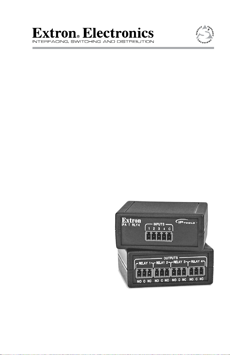
Description
The Extron IPA T RLY4 Relay Accessory is an IPLink® Accessory
product. The Relay Accessory consists of four output relays with
normally open (when the relay is de-energized) (NO) and normally
closed (NC) contacts.
The Relay Accessory converts a solid state (up to 12 VDC) signal, from
a source such as the Flex I/O port of an Extron IPL T SF24 or the digital
I/O port of an MLC 104 IP Plus, to a relay contact closure. The relay
contacts can handle up to 24 VAC or 24 VDC as a tally signal, contact
closure signal, or control signal to drive devices in your system, such
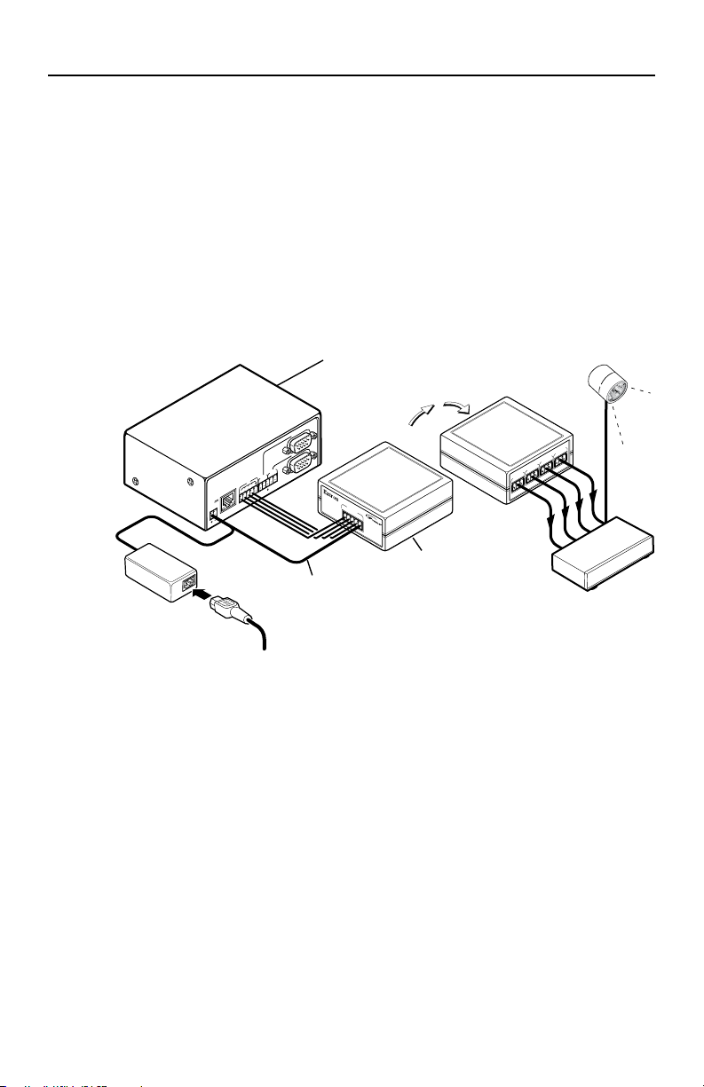
as a lighting system (figure 1) or remote screens. The relay contacts are
protected by an overvoltage circuit.
Figure 1 — Typical IPA T RLY 4 application
The compact IPA T RLY4 can be concealed out of the way anywhere in
your system with the included Velcro® strip.
1 IPATRLY4•Introduction

IPA T RLY4
1 2 3 4 C
INPUTS
NO C NC
NO C NC NO C NC NO C NC
RELAY 1
RELAY 2
RELAY 3
RELAY 4
2 2 2 2
1
Connections
N
The 5-pole captive screw input connector and four 3-pole captive
screw output connectors are included with the unit, but you
must supply the cable. Extron recommends its CTL Series cable,
part #22-148-nn (non-plenum bulk rolls), 26-119-nn (plenum
bulk rolls), or 26-461-nn (plenum pre-cut lengths).
Figure 2 — IPA T RLY4 connections
Input connections
Inputs — Connect the 12 VDC source to the common voltage (C)
a
terminal of the 5-pole captive screw connector. Connect the
appropriate input terminal (1 through 4) to the digital output(s) of
the IPL T SF24, MLC 104 IP Plus, or other device.
C Connect +12 VDC to the C pin only and
connect the return to one or all of the Input pins
(1 through 4) for the relays that you will use.
Reversing the connections can damage the power
supply.
N
Connect the I/O control line to the Input 1 terminal for
relay 1, Input 2 for relay 2, and so on.
IPATRLY4•Connections
2

Connections
1
2
3
GROUND
+12V OUT
CM
GROUND
IR OUT
GROUND
SCP
GROUND
Tx
Rx
DISPLAY
RS-232/IR
A B C D E
COMM LINK
LAN
PRESS TAB WITH
TWEEKER TO REMOVE
A B
MLS
RS-232
POWER
12V
DIGITAL
I/O
IR IN
Tx
GROUND
Rx
+12V IN
IPA T RLY4
1 2 3 4 C
INPUTS
MLC 104 IP Plus
Right Side
Observe proper polarity when making connections to the
MLC 104 IP Plus controller’s Power port.
Miswiring can damage the controller’s Digital I/O port.
IPA T RLY4
Front Panel
Relay 1
Relay 2
Relay 3
+12 VDC
CAUTION
N
Figure 3 is a wiring diagram of a typical application: an Extron
MLC 104 IP Plus controlling an IPA T RLY4 relay function.
Refer to the MLC 104 Plus Series Manual for information on
configuring the MLC to control the IPA T RLY4.
Figure 3 — Wiring diagram for connection to an
MLC 104 IP Plus
Output connections
Outputs — For each relay:
b
For the normally open contacts, connect a device between the NO
and C terminals of the 3-pole captive screw connectors.
For the normally closed contacts, connect a device between the
NC and C terminals of the 3-pole captive screw connectors.
IPATRLY4•Connections
3

Connections
NO C NC
NO C NC NO C NC NO C NC
RELAY 1
RELAY 2
RELAY 3
RELAY 4
NO C NC
NO C NC NO C NC NO C NC
RELAY 1
RELAY 2
RELAY 3
RELAY 4
For a typical Stewart screen controller,
a momentary closure on relay 1, 2, or 3
causes the screen to move up, down,
or stop.
UP DOWN STOP
Typical Stewart Low Voltage Controller
COMMON
RED BLACK
Typical Da-Lite or Draper Low Voltage Controller
WHITE (DA-LITE)
BLUE (DRAPER)
IPA T RLY4
NOTE
For a typical Da-Lite or Draper screen controller,
a momentary closure on relay 1 or 2 causes the
screen to move up or down. A momentary
closure on relay 3 causes the screen to stop in
its current position. Use 1N4001 or equivalent
diodes (not included) for reverse bias protection.
Recommended diode specifications:
100 mA maximum through diode
50 V maximum reverse bias
NOTE
IPA T RLY4
I/O state Relay state
NCNO
Output
On (closed) Closed Open
Off (open)
Open Closed
I/O mode
N
Figure 4 is a wiring diagram of a typical application: an Extron
IPA T RLY4 driving a screen controller. Please be aware that
these are examples only. Your equipment may have different
wiring requirments. Refer to the manual from the applicable
manufacturer for specific wiring instructions.
Figure 4 — Wiring diagram for connection to a screen
controller
Operation
When an input signal is applied to one of the relays, the signal toggles
the state of that IPA T RLY4’s output relay; the relay’s NO contacts close,
routing the signal for the connected device, and its NC contacts open,
interrupting the signal for the connected device. See the chart below for
clarification.
4 IPATRLY4•Operation

Specifications
Extron USA - West
Headquarters
+800.633.9876
Inside USA / Canada Only
+1.714.491.1500
+1.714.491.1517 FAX
Extron USA - East
+800.633.9876
Inside USA / Canada Only
+1.919.863.1794
+1.919.863.1797 FAX
Extron Europe
+800.3987.6673
Inside Europe Only
+31.33.453.4040
+31.33.453.4050 FA X
Extron Asia
+800.7339.8766
Inside Asia Only
+65.6383.4400
+65.6383.4664 FAX
Extron Japan
+81.3.3511.7655
+81.3.3511.7656 FAX
Extron China
+400.883.1568
Inside China Only
+86.21.3760.1568
+86.21.3760.1566 FAX
Extron Middle East
+971.4.2991800
+971.4.2991880 FAX
Relay control
Relay control ports number/type .. 4 momentary
Relay control connectors .............. (1) 3.5 mm captive screw connectors, 5 pole,
for control input and power
(4) 3.5 mm captive screw connectors, 3 pole,
NO & NC for configurable relay outputs
Relay coil operating current ........ 0.015 A (nominal), 0.025 A (maximum). The coil
limits the current; no external resistance is required.
Relay control contact rating ......... 24 V, 1 A
General
Temperature/humidity ................ Storage: -40 to +158 °F (-40 to +70 °C) /
10% to 90%, noncondensing
Operating: +32 to +122 °F (0 to +50 °C) /
10% to 90%, noncondensing
Rack mount .................................... No
Enclosure type .............................. Plastic
Enclosure dimensions .................. 1.0" H x 2.4" W x 2.3" D
2.5 cm H x 6.1 cm W x 5.8 cm D
Product weight .............................. 0.1 lb (<0.1 kg)
Shipping weight ........................... 1 lb (1 kg)
Vibration ........................................ ISTA 1A in carton
(International Safe Transit Association)
Listings............................................ UL, CUL
Compliances ................................... CE, FCC Class A, VCCI, AS/NZS, ICES
MTBF ............................................... 30,000 hours
Warranty ........................................ 3 years parts and labor
N
N
All nominal levels are at ±10%.
Specifications are subject to change without notice.
FCC Class A Notice
This equipment has been tested and found to comply with the limits for a Class A digital device, pursuant
to part 15 of the FCC Rules. Front Panel Operation is subject to the following two conditions: (1) this device
may not cause harmful interference, and (2) this device must accept any interference received, including
interference that may cause undesired operation. The Class A limits are designed to provide reasonable
protection against harmful interference when the equipment is operated in a commercial environment.
This equipment generates, uses, and can radiate radio frequency energy and, if not installed and used in
accordance with the instruction manual, may cause harmful interference to radio communications. Front
Panel Operation of this equipment in a residential area is likely to cause harmful interference, in which case
the user will be required to correct the interference at his own expense.
N
This unit was tested with shielded cables on the peripheral devices. Shielded cables must be used with the
unit to ensure compliance with FCC emissions limits.
© 2009 Extron Electronics. All rights reserved.
 Loading...