

Extreme Networks E4G Series Installation Manual

Extreme Networks E4G Series Routers
Hardware Installation Guide
Extreme Networks, Inc.
3585 Monroe Street
Santa Clara, California 95051
(888) 257-3000
(408) 579-2800
http://www.extremenetworks.com
Published: February 2012
Part number: 120728-00 Rev. 01

AccessAdapt, Alpine, Altitude, BlackDiamond, Direct Attach, EPICenter, ExtremeWorks Essentials, Ethernet
Everywhere, Extreme Enabled, Extreme Ethernet Everywhere, Extreme Networks, Extreme Standby Router
Protocol, Extreme Turbodrive, Extreme Velocity, ExtremeWare, ExtremeWorks, ExtremeXOS, Go Purple Extreme
Solution, ExtremeXOS ScreenPlay, ReachNXT, Ridgeline, Sentriant, ServiceWatch, Summit, SummitStack, Triumph,
Unified Access Architecture, Unified Access RF Manager, UniStack, XNV, the Extreme Networks logo, the Alpine
logo, the BlackDiamond logo, the Extreme Turbodrive logo, the Summit logos, and the Powered by ExtremeXOS
logo are trademarks or registered trademarks of Extreme Networks, Inc. or its subsidiaries in the United States
and/or other countries.
sFlow is the property of InMon Corporation.
Specifications are subject to change without notice.
All other registered trademarks, trademarks, and service marks are property of their respective owners.
© 2012 Extreme Networks, Inc. All Rights Reserved.
2
E4G Series Routers Hardware Installation Guide

Contents
Preface......................................................................................................................................................... 7
Audience ..................................................................................................................................................................7
Conventions .............................................................................................................................................................8
Related Publications.................................................................................................................................................8
PART 1: ABOUT THE E4G SERIES ROUTERS
Chapter 1: About the E4G Series Routers .............................................................................................13
Overview ................................................................................................................................................................13
E4G-200 Cell Site Router.......................................................................................................................................14
E4G-200 CLK Module .....................................................................................................................................16
E4G-200 F16T1E1 Module .............................................................................................................................16
E4G-200 LEDs ................................................................................................................................................17
E4G-400 Cell Site Aggregation Router...................................................................................................................18
Combination Ports on the E4G-400 Router ....................................................................................................20
LEDs ...............................................................................................................................................................20
Power Supplies for the E4G-400.....................................................................................................................22
Optional Ports for the E4G-400 Router ...........................................................................................................23
XGM3S-2sf Option Card ..........................................................................................................................23
XGM3S-2xf Option Card ..........................................................................................................................23
XGM3SB-4sf Option Card........................................................................................................................24
E4G-B16T1E1 Option Card .....................................................................................................................24
Pluggable Interfaces for E4G Series Routers.........................................................................................................25
PART 2: INSTALLING HARDWARE
Chapter 2: Site Preparation .....................................................................................................................29
Planning Your Site..................................................................................................................................................30
Meeting Site Requirements ....................................................................................................................................30
Operating Environment Requirements............................................................................................................30
Building and Electrical Codes ..................................................................................................................30
Equipment Location Considerations ........................................................................................................31
Temperature ............................................................................................................................................32
Humidity ...................................................................................................................................................32
Spacing Requirements and Airflow..........................................................................................................32
Electrostatic Discharge ............................................................................................................................33
Rack and Cabinet Specifications and Recommendations...............................................................................33
Mechanical Recommendations for the Rack............................................................................................33
Protective Grounding for the Rack...........................................................................................................34
Space Requirements for an E4G-400 Router..........................................................................................34
Securing the Rack....................................................................................................................................34
Outdoor Installation Sites................................................................................................................................35
Evaluating and Meeting Cable Requirements ........................................................................................................35
Cabling Standards...........................................................................................................................................36
Cable Labeling and Record Keeping ..............................................................................................................36
Installing Cable................................................................................................................................................36
Fiber Optic Cable .....................................................................................................................................38
Cable Distances.......................................................................................................................................39
E4G Series Routers Hardware Installation Guide
3

Contents
RJ-45 Connector Jackets................................................................................................................................40
Radio Frequency Interference.........................................................................................................................40
Meeting Power Requirements ................................................................................................................................41
Power Supply Requirements...........................................................................................................................41
AC Power Cables............................................................................................................................................41
Uninterruptible Power Supply Requirements ..................................................................................................42
Selecting a UPS.......................................................................................................................................42
Calculating Volt-Amperage Requirements ...............................................................................................42
UPS Transition Time................................................................................................................................43
DC Power Requirements ................................................................................................................................43
Applicable Industry Standards................................................................................................................................43
Chapter 3: Installing an E4G Series Router ...........................................................................................45
Pre-installation Requirements ................................................................................................................................45
Installing the E4G-200 Cell Site Router..................................................................................................................46
Installing the Router in the Rack .....................................................................................................................47
Grounding the Router......................................................................................................................................48
Preparing the DC Power Input Cable..............................................................................................................49
Connecting the Router to DC Power...............................................................................................................50
Installing and Connecting a Clock Module ......................................................................................................51
Connecting Timing Cables to the E4G-200 Router..................................................................................52
Installing a T1/E1 Module................................................................................................................................52
Connecting the Alarms Cable .........................................................................................................................53
Installing the E4G-400 Cell Site Aggregation Router .............................................................................................54
Mid-Mounting an E4G-400 Router in a Two-Post Rack ..................................................................................55
Front-Mounting an E4G-400 Router in a Two-Post Rack................................................................................56
Installing an AC Power Supply........................................................................................................................57
Installing a DC Power Supply..........................................................................................................................58
Preparing the DC Cables .........................................................................................................................58
Installing the Power Supply......................................................................................................................59
Connecting the Ground Wire ...................................................................................................................60
Connecting the Power Supply to the DC Source Voltage........................................................................61
Installing Port Option Cards ............................................................................................................................63
Connecting Timing Cables to the E4G-400 Router.........................................................................................64
Connecting Cables to the E4G-B16T1E1 Module...........................................................................................65
Initial Startup ..........................................................................................................................................................66
Initial Management Access ....................................................................................................................................66
Connecting Equipment to the Console Port ....................................................................................................66
Logging In for the First Time ...........................................................................................................................67
PART 3: MAINTENANCE
Chapter 4: Maintenance Procedures ......................................................................................................71
Replacing an AC Power Supply in the E4G-400 Router ........................................................................................71
Replacing a DC Power Supply in the E4G-400 Router ..........................................................................................74
Removing the Power Supply...........................................................................................................................74
Installing the Replacement Power Supply.......................................................................................................75
Connecting the Ground Wire...........................................................................................................................75
Connecting the DC Power Cables ..................................................................................................................76
Replacing a Fan Module in the E4G-400 Router....................................................................................................78
Replacing Optional Ports in the E4G-400 Router...................................................................................................79
Replacing a Clock Module in the E4G-200 Router.................................................................................................80
Replacing a T1E1 Module in the E4G-200 Router .................................................................................................81
Removing an E4G-200 Router from an Equipment Rack.......................................................................................82
Removing an E4G-400 Router from an Equipment Rack.......................................................................................83
Removing a 300 W AC Power Supply.............................................................................................................83
4
E4G Series Routers Hardware Installation Guide

Contents
Removing a 300 W DC Power Supply ............................................................................................................83
Removing the E4G-400 Router from the Rack................................................................................................84
PART 4: APPENDICES
Appendix A: Safety Information .............................................................................................................. 87
Considerations Before Installing.............................................................................................................................88
General Safety Precautions ...................................................................................................................................88
Maintenance Safety................................................................................................................................................89
Cable Routing for LAN Systems.............................................................................................................................89
Installing Power Supply Units and Connecting Power............................................................................................90
Selecting Power Supply Cords...............................................................................................................................91
Battery Replacement and Disposal ........................................................................................................................92
Fiber Optic Ports and Optical Safety......................................................................................................................92
SFP (Mini-GBIC), SFP+, and XFP Regulatory Compliance............................................................................93
Safety Information for the E4G Series Routers......................................................................................................93
Appendix B: Technical Specifications ................................................................................................. 101
E4G-200 Cell Site Router.....................................................................................................................................101
E4G-400 Cell Site Aggregation Router.................................................................................................................105
Power Supplies for the E4G-400 Router..............................................................................................................111
Power Cord Requirements for AC Power Supplies.......................................................................................112
E4G-200 Connector Pinouts ................................................................................................................................113
E4G-400 Connector Pinouts ................................................................................................................................116
Conformity Statements.........................................................................................................................................120
Declaration of Conformity to R&TTE Directive 1999/5/EC for the European Community, Switzerland, Norway,
Iceland, and Liechtenstein ............................................................................................................................120
EMC Class A Statements..............................................................................................................................121
International—CISPR 22 Class A ..........................................................................................................121
FCC Class A ..........................................................................................................................................121
Canada Class A .....................................................................................................................................121
Japan (VCCI Class A)............................................................................................................................121
Class A Notice for Taiwan and Other Traditional Chinese Markets .......................................................122
Telecom Approvals .......................................................................................................................................122
FCC Part 68 Notice................................................................................................................................122
Canada CS-03 Certification ...................................................................................................................122
Japan: JATE Green Book ......................................................................................................................123
GR-1089-CORE Issue 6 Documentation Statements ...................................................................................123
ESD Mitigation .......................................................................................................................................123
Telcordia GR-1089 NEBS Standard for Electromagnetic Compatibility and Safety...............................123
Intrabuilding Lightning Surge and AC Power Fault ................................................................................123
Equipment Bonding Networks................................................................................................................124
Equipment Interfacing with AC Power Ports..........................................................................................124
E4G Series Routers Hardware Installation Guide
5

Contents
6
E4G Series Routers Hardware Installation Guide

Preface
NOTE
This guide provides the instructions and supporting information needed to install the Extreme
Networks
®
E4G series routers.
The guide includes information about site preparation and router functionality.
Audience
This guide is intended for use by network administrators and equipment installers who are responsible
for installing and setting up network equipment. It assumes a basic working knowledge of:
● Standard equipment installation procedures, including remote location and electrical safety practices
● Local area networks (LANs)
● Ethernet concepts
● Ethernet switching and bridging concepts
● Routing concepts
● Time division multiplexing (TDM)
● Simple Network Management Protocol (SNMP)
See the ExtremeXOS Concepts Guide and the ExtremeXOS Command Reference Guide for information about
configuring Extreme Networks E4G series routers.
If the information in an installation note or release note shipped with your Extreme Networks equipment
differs from the information in this guide, follow the installation or release note.
E4G Series Routers Hardware Installation Guide
7
Preface
Conventions
Tab le 1 and Ta bl e 2 list conventions used throughout this guide.
Table 1: Notice Icons
Icon Notice Type Alerts you to...
Note Important features or instructions.
Caution Risk of personal injury, system damage, or loss of data.
Warning Risk of severe personal injury.
Table 2: Text Conven ti ons
Convention Description
Screen displays This typeface represents information as it appears on the screen, or command
syntax.
Words in italicized type Italics emphasize a point of information or denote new terms at the place where
they are defined in the text.
Book titles are printed in italics.
Related Publications
The documentation set for Extreme Networks ExtremeXOS® switches and routers includes:
●
ExtremeXOS Concepts Guide
●
ExtremeXOS Command Reference Guide
●
ExtremeXOS Release Notes
●
ExtremeXOS Hardware and Software Compatibility Matrix
● Extreme Networks E4G Series Routers Hardware Installation Guide (this guide)
●
BlackDiamond 8800 Series Switches Hardware Installation Guide
●
BlackDiamond X8 Series Switches Hardware Installation Guide
● BlackDiamond
●
BlackDiamond 10808 Switch Hardware Installation Guide (legacy product)
●
BlackDiamond 12800 Series Switches Hardware Installation Guide (legacy product)
● Summit Family Switches Hardware Installation Guide
●
Extreme Networks Pluggable Interface Modules Installation Guide
Hardware and software documentation for Extreme Networks products is available from the Extreme
Networks website at the following location:
http://www.extremenetworks.com/go/documentation
®
20800 Series Switches Hardware Installation Guide (legacy product)
8
E4G Series Routers Hardware Installation Guide

NOTE
Related Publications
You can download software concepts guides and reference guides, hardware installation guides, and
other documents.
Under your product warranty or with a current support contract, you can access software release notes
and entitled software from the eSupport web pages at:
https://esupport.extremenetworks.com/
For instructions on accessing and downloading software and software release notes, see the Technical
Assistance Center User Guide at:
http://www.extremenetworks.com/services/tac-userguide.aspx
You must have an active support agreement or a product registered to you in order to receive an eSupport
login and access to Extreme Networks software release notes.
To request an eSupport user name and password, select the Request Web Login link on the eSupport
home page at:
https://esupport.extremenetworks.com
You can see complete information about all of our services online at:
http://www.extremenetworks.com/solutions/service-solutions.aspx
E4G Series Routers Hardware Installation Guide
9

Preface
10
E4G Series Routers Hardware Installation Guide

PA RT
About the E4G Series
Routers


About the E4G Series Routers
1
CHAPTER
This chapter describes the Extreme Networks E4G series routers and includes the following sections:
● Overview on page 13
● E4G-200 Cell Site Router on page 14
● E4G-400 Cell Site Aggregation Router on page 18
● Pluggable Interfaces for E4G Series Routers on page 25
Overview
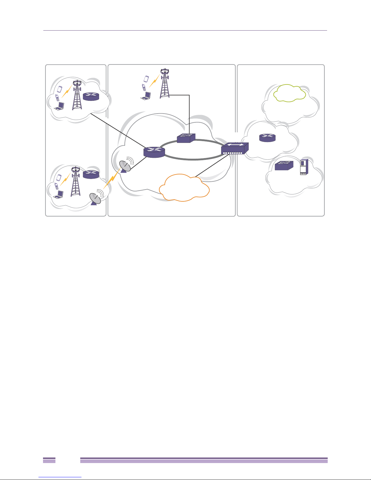
The Extreme Networks E4G router family consists of the E4G-200 cell site router and the E4G-400 cell
site aggregation router. These routers provide high-bandwidth capacity, highly accurate and flexible
timing, and Operations Administration and Maintenance (OAM) capabilities that support service level
agreement (SLA) metrics. They support time-division multiplexing pseudowire end-to-end emulation
(TDM PWE3). PWE allows the simultaneous support of multiple generations of services (2G, 3G and
4G) over the same Ethernet backhaul network without having to remove legacy T1/E1 equipment and
incur associated costs.
The E4G-200 Cell Site Router collects traffic from cell site towers for handoff to the mobile backhaul
network. The E4G-200 router connects to the E4G-400 Cell Site Aggregation Router, which aggregates
T1, E1. and Ethernet traffic for handoff to the mobile core (see Figure 1).
E4G Series Routers Hardware Installation Guide
13
Chapter 1: About the E4G Series Routers
CSR_025
Data Center
Switch
Servers and
Storage
Mobile Data
Center
Mobile Core
Cell Site
Router
Cell Site
Router
Cell-Site
Aggregation
Router
Cell-Site AggregationCell Site
Aggregation
Hub
Building Integrated
Timing System
Stratum Timing
GE over Fiber
Resilient Synchronous
Gigabit Ethernet
2G / 3G / 4G
2G/3G/4G
2G/3G/4G
Microwave
Microwave
2G/3G/4G
Mobile Service
Core
Packet Core
Network
Figure 1: Mobile Backhaul Architecture
E4G-200 Cell Site Router
The Extreme Networks E4G-200 router provides 12 resilient synchronous Gigabit Ethernet ports and 16
T1/E1 ports in a compact 1RU unit. The Ethernet ports support both IEEE 1588v2 and Synchronous
Ethernet (SyncE) timing, and the T1/E1 ports support time division multiplexing (TDM) timing. The
router provides high-performance pseudowire capability, supporting both CESoPSN (channelized) and
SAToP (unframed and unchannelized) TDM services. Deployed at the cell site, the E4G-200 cell site
router collects traffic from 2G, 3G, and 4G radio towers for handoff to the mobile backhaul over fiber
or microwave.
The E4G-200 extended temperature range of -40°C to +65°C allows service providers to deploy the
E4G-200 router at sites without climate control.
The E4G-200 cell site router front panel (Figure 2) has the following features:
● Alarms port implemented as a DB-15 connector.
For details about the connector, see “E4G-200 Connector Pinouts” on page 113.
● Management and console ports
● Eight 10/100/1000BASE-T (RJ-45) dedicated ports
● Four 100/1000BASE-X (SFP) ports
These ports require Extreme Networks optical modules that are designed for use within the
temperature range of the router.
● Slot for hot-swappable clock module
● Slot for hot-swappable T1/E1 module with 16 ports
14
E4G Series Routers Hardware Installation Guide
CSR_020
1
7
8
2 3 54 6
1 = Alarms connection
2 = Management and console ports
3 = RJ-45 dedicated ports
4 = SFP ports
5 = Slot for E4G-200 CLK module
6 = Slot for F16T1E1 module
7 = Grounding lug
8 = DC input power connectors
E4G-200 Cell Site Router
● Grounding lug
● Redundant DC input power connectors
Figure 2: E4G-200 Cell Site Router Front Panel
The alarms interface is implemented as a DB-15 female connector. This interface relays alarms to an
external device (output alarms) and monitors alarms from an external device (input alarms). The alarms
are controlled from the ExtremeXOS software.
The alarms interface provides two input alarms and eleven output alarms. Input alarms can be
configured to monitor alarms from an external source and raise a trap or flag, or to be an input source
to clear Minor or Major alarms. The output alarms can be connected to an external visual or an audible
interface. The output alarms can be either persistent or non-persistent. For information about
configuring alarms, refer to the ExtremeXOS Concepts Guide.
For details about the connector, see “E4G-200 Connector Pinouts” on page 113.
The E4G-200 router has an integrated DC power supply with dual feeds on the front panel. Power
feed A can be connected to one power source and power feed B can be connected to a different power
source to provide protection should either source of power fail. The power supply is not
field-replaceable.
The back panel of the E4G-200 router provides an alternate attachment point for the grounding lug.
Status LEDs on the E4G-200 router are described in Ta bl e 3 on page 17.
E4G Series Routers Hardware Installation Guide
15
CSR_012
1 32
1 = LED
2 = Sync In/Sync Out interfaces
3 = BITS IN interface
CSR_015
1 2
1 = LEDs
2 = T1/E1 ports
Chapter 1: About the E4G Series Routers
E4G-200 CLK Module
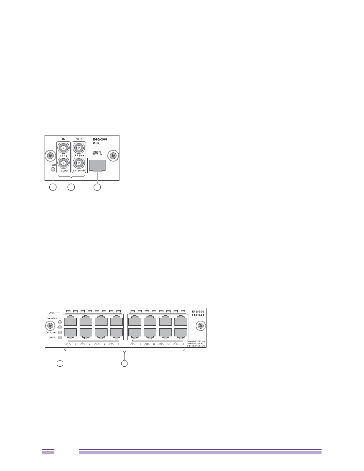
An optional clock module (Figure 3) for the E4G-200 router provides timing based on either of the
following protocols:
● ITU-T Synchronous Ethernet (SyncE) protocol
● Precision Time Protocol based on the IEEE specification 1588v2
The clock module has four mini-BNC connectors providing Sync In/Sync Out timing interfaces and an
RJ-45 connector that provides an RS-422 BITS-IN interface. Clock modules can be installed or removed
without powering down the router, although a system reboot is required to initialize the module.
Figure 3: E4G-200 Clock Module
E4G-200 F16T1E1 Module
The F16T1E1 module for the E4G-200 router provides 16 T1/E1 ports implemented as RJ-45 connectors
(Figure 4. These support circuit emulations via industry-standard pseudowires, allowing the
transformation of TDM cell sites to Ethernet/IP/MPLS cell sites. T1/E1 modules can be installed
or removed without powering down the router, although a system reboot is required to initialize
the module.
Figure 4: E4G-200 F16T1E1 Module
16
E4G Series Routers Hardware Installation Guide

E4G-200 Cell Site Router
E4G-200 LEDs
Tab le 3 describes the LEDs on the E4G-200 Cell Site Router.
Table 3: LEDs on the E4G-200 Cell Site Router
Label/type Color/State Meaning
System LEDs
MGMT Steady green Power-on self- test (POST) passed, normal operation
Blinking green POST in progress
Amber POST failed or system has overheated.
Off No power
FAN Steady green Normal operation
Blinking amber Failure
Off No power
PSU-1, PSU-2 Steady green Normal operation.
Blinking amber Power failure.
Off No power attached to this connector.
MGMT Port LEDs
ACT Blinking green Packet transmitting or receiving
Off No packet transmitting or receiving
LINK Blinking green Link up
Off No link or port disabled
Port LEDs
Ports 1 through 8
(above ports)
Ports 9
through 12
(on SFP cages)
Steady green Link exists
Blinking green Activity occurring
Off No link or port is disabled
Steady green Link exists
Blinking green Activity occurring
Off No link or port is disabled
Clock Module LED
PWR Steady green 3.3V power OK
Off No power
F16T1E1 Module LEDs
Local
(Alarm LED)
Remote
(Alarm LED)
On-Line Steady green On line
E4G Series Routers Hardware Installation Guide
Steady green Local alarm active
Blinking green Local alarm active but silenced
Off No local alarm active
Steady green Remote alarm active
Blinking green Remote alarm active but silenced
Off No remote alarm active
Off Off line
17

Chapter 1: About the E4G Series Routers
Table 3: LEDs on the E4G-200 Cell Site Router (Continued)
Label/type Color/State Meaning
PWR Steady green Normal operation
Off No power
Port LEDs
(1 through16)
Steady green Link OK
Blinking green Activity
Off No link, or port is disabled.
E4G-400 Cell Site Aggregation Router
The E4G-400 cell site aggregation router is a 1RU unit that allows networks to aggregate multiple
Ethernet links from various cell sites and route the traffic to the mobile core. The E4G-400 router
provides 28 Gigabit Ethernet ports and port options for up to six 10-Gigabit Ethernet ports, as well as a
16-port T1/E1 module with pseudowire capability. The T1/E1 module is used where 2G and 3G radios
are co-located at the aggregation site, and eliminates the need for separate cell site routers.
The Gigabit and 10-Gigabit Ethernet ports on the E4G-400 router support Synchronous Ethernet (SyncE)
and IEEE 1588v2 timing. Integrated timing connectors on the front panel provide timing based on either
the ITU-T Synchronous Ethernet (SyncE) protocol or the Precision Time Protocol based on IEEE
specification 1588v2. Four mini-BNC connectors providing Sync In/Sync Out timing interfaces and an
RJ-422 connector provides a BITS-IN interface.
The E4G-400 router has 4 shared ports. For each pair of shared ports, either the 10/100/1000BASE-T
port (RJ45) or 100/1000BASE-X (SFP) port can be used as needed.
The E4G-400 router supports stacking using ports on installed port option cards at the back of the unit.
Up to eight units can be connected into a single management entity that has up to 192 Gigabit Ethernet
ports and up to 32 10-Gigabit Ethernet ports.
At the back of the unit are two bays for either AC or DC power supplies. One 300 W AC or DC power
supply is included with the base unit. A redundant power supply must be ordered separately. You can
mix any combination of 300 W AC and DC power supplies based on the need at the particular site. For
example, you can have a DC main power feed and an AC input backup from an uninterruptible power
supply (UPS).
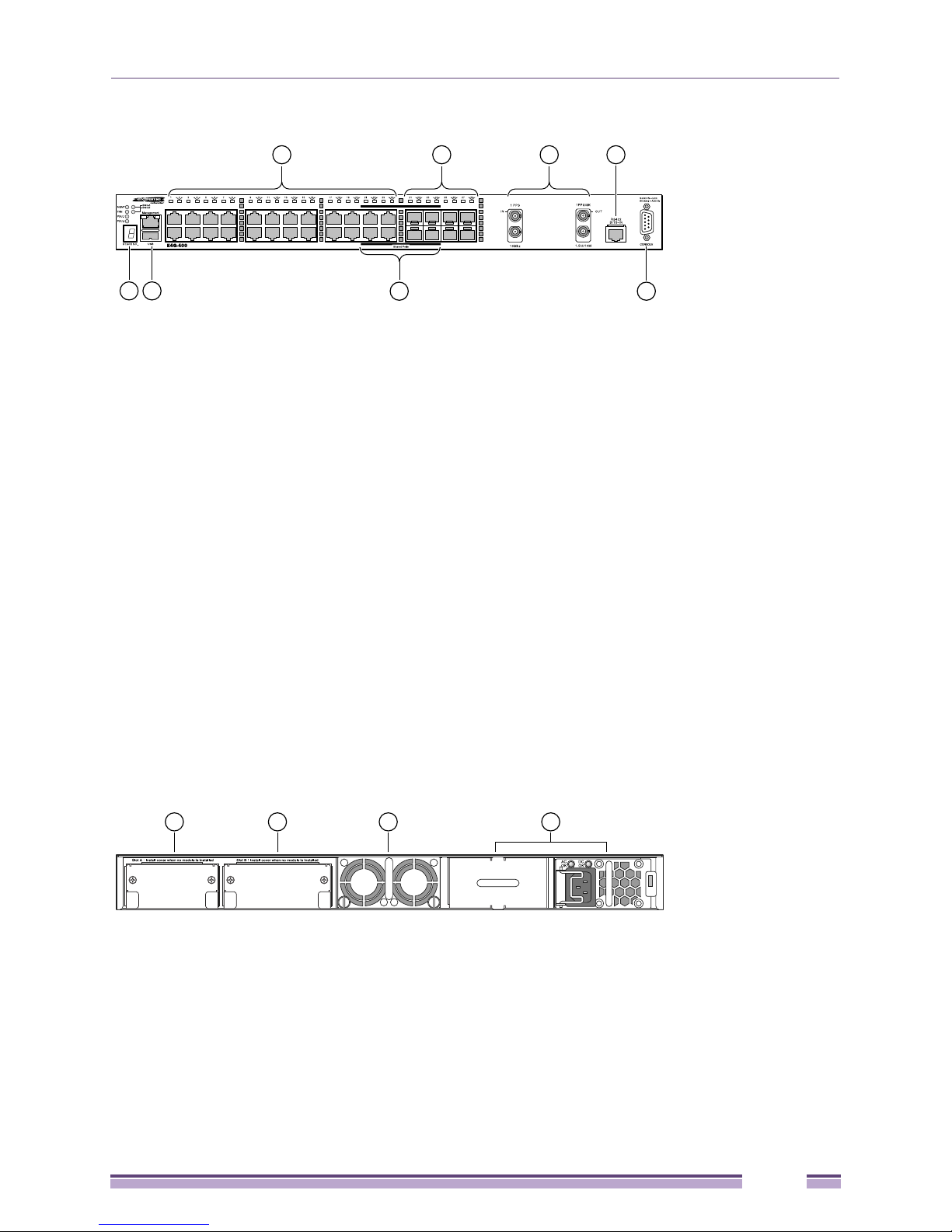
The front panel of the E4G-400 router (Figure 5) has the following features:
● Twenty 10/100/1000BASE-T (RJ-45) dedicated ports
● Four 100/1000BASE-X (SFP) or 10/100/1000BASE-T (RJ-45) shared ports
● Four 100/1000BASE-X (SFP) dedicated ports
● Timing interfaces
● BITS-IN interface
● Console port
● Stack number indicator
● Management and USB ports
18
E4G Series Routers Hardware Installation Guide
CSR_001
2 3 41
8
7
5 6
1 = RJ-45 ports
2 = SFP ports
3 = Timing connections (Mini-BNC connectors)
4 = BITS IN connector (RJ-45 connector)
5 = Stack number indicator
6 = Management and USB ports
7 = Shared ports
8 = Console port
CSR_021
1 2 3 4
1 = Slot A
2 = Slot B
3 = Fan tray
4 = Power supply bays
E4G-400 Cell Site Aggregation Router
Figure 5: E4G-400 Front Panel
Status LEDs on the E4G-400 router are described in Ta bl e 4 on page 20.
The rear panel of the E4G-400 router (Figure 6) has the following features:
● Slot A for one of the following port option cards:
- XGM3S-2xf option card (2 XFP with Sync-E for stacking or data links)
- XGM3S-2sf option card (2 SFP+ with Sync-E for stacking or data links)
● Slot B for one of the following optional port cards:
- XGM3SB-4sf option card (4 SFP+ with Sync-E for data links)
- E4G-B16T1E1 option card (2 MRJ21 with 8 TDM ports per MRJ21 connector)
Option cards in Slot A and Slot B are hot-pluggable.
● Hot-swappable fan tray
● Two bays for AC or DC power supplies
To provide redundant power to the router, you can install two AC power supplies, two DC power
supplies, or a combination of an AC and DC power supply.
Figure 6: E4G-400 Back Panel
E4G Series Routers Hardware Installation Guide
19

Chapter 1: About the E4G Series Routers
Combination Ports on the E4G-400 Router
The E4G-400 Cell Site Aggregation Router provides four uplink ports implemented as combination
ports that pair a copper port using RJ-45 connectors with an optical port using LC connectors. The
copper port operates as an autonegotiating 10/100/1000BASE-T port. The optical port allows Gigabit
Ethernet uplink connections through Extreme Networks small form factor pluggable (SFP) interface
modules.
The E4G-400 router supports automatic failover from an active fiber port to a copper backup or from an
active copper port to a fiber port. If one of the uplink connections fails, the uplink connection
automatically fails over to the second connection. To set up a redundant link on a combination port,
connect the active 1000BASE-T and fiber links to both the RJ-45 and SFP interfaces of that port.
Gigabit Ethernet uplink redundancy on the E4G-400 router follows these rules:
● With both the SFP and 1000BASE-T interfaces connected on a combination port, only one interface
can be activated. The other is inactive.
● If only one interface is connected, the switch activates the connected interface.
● The router determines whether the port uses the fiber or copper connection based on the order in
which the connectors are inserted into the router. When the router senses that an SFP and a copper
connector are inserted, the router enables the uplink redundancy feature. For example, if you first
connect copper ports 21 and 22, and then insert SFPs into optical ports 21 and 22, the router assigns
the copper ports as active ports and the fiber ports as redundant ports.
Hardware identifies when a link is lost and responds by swapping the primary and redundant ports to
maintain stability. After a failover occurs, the router keeps the current port assignment until another
failure occurs or a user changes the assignment using the CLI. For more information about configuring
automatic failover on combination ports, see the ExtremeXOS Concepts Guide.
LEDs
Tab le 4 describes the LEDs on the E4G-400 Cell Site Aggregation Router
Table 4: LEDs on the E4G-400 Cell Site Aggregation Router
Type/Label Color/State Meaning
Front Panel LEDs
MGMT Steady green Power-on self test (POST) completed successfully; normal
operation.
Blinking green POST is in progress.
Amber POST failed, or the system has over-heated.
Off No external power attached.
FAN Steady green Normal operation.
Blinking amber Failure.
Off No power.
PSU-1, PSU-2 Steady green Normal operation.
Steady amber Power is attached, but no power is on.
Blinking amber Failure.
Off No power is attached.
20
E4G Series Routers Hardware Installation Guide

E4G-400 Cell Site Aggregation Router
Table 4: LEDs on the E4G-400 Cell Site Aggregation Router (Continued)
Type/Label Color/State Meaning
Slot-A, Slot-B Steady green Port option card is installed in the indicated slot at the back
of the router.
Off No port option card is installed in the indicated slot at the
2-digit Stack Number Indicator
Left digit (1) Reserved for future use
Right digit (1 – 8)
Indicates the position
of this router in a
stacked configuration.
Ethernet Ports
1 through 28
Management Port Steady green Link OK
Back Panel
Port LED on installed
XGM3S-2sf option card
Port LED on installed
XGM3S-2xf option card
Port LED on installed
XGM3SB-4xf option
card (S1 through S4)
Port LED on installed
E4G-B16T1E1 module
(1 through16)
Upper half blinking This router is the stack master node.
Lower half blinking This router is the stack backup node.
Lit steadily This router is a standby node in the stack.
Steady green Link OK
Blinking green Activity
Off No link, or port is disabled.
Blinking green Activity
Off No link, or port is disabled.
Steady green Link OK
Blinking green Activity
Off No link, or port is disabled.
Steady green Link OK
Blinking green Activity
Off No link, or port is disabled.
Steady green Link OK
Blinking green Activity
Off No link, or port is disabled.
Steady green Link OK
Blinking green Activity
Off No link, or port is disabled.
back of the router.
E4G Series Routers Hardware Installation Guide
21
NOTE
Chapter 1: About the E4G Series Routers
Power Supplies for the E4G-400
The E4G-400 router is compatible with the following power supplies:
● 300W AC power supply (model number 10930A)
● 300W DC power supply (model number 10934A)
An E4G-400 router accommodates one or two 300 W power supplies. You can combine AC and DC
power supplies in the same E4G-400 router. In a redundant power configuration, both power supplies
are fully fault-tolerant and load-sharing. You can remove one power supply without interrupting
router operation.
An AC power input cord is not provided with a 300 W AC power supply. You can order an appropriate cord
from Extreme Networks or from your local supplier. The power cord must meet the requirements listed in “Power
Supplies for the E4G-400 Router” on page 111.
The 300 W AC power supply has the status LEDs listed in Ta bl e 5.
Table 5: 300 W AC Power Supply LEDs
LED Label and Color
AC
OK
Green
Off Off No AC input power
Off Steady red No AC input power; receiving standby output from system.
On Off AC input good; 12 V output is disabled. Standby output is ON.
On Steady red AC input good; fault in 12 V output.
On Flashing green
On Steady green AC input good; DC outputs good.
DC OK
Green/red
bicolor
and red
Meaning
AC input good, 12 V output good.
Power supply alert: power supply is likely to fail because of a developing fault,
such as abnormal thermal conditions or poor fan performance.
The 300 W DC power supply has the status LEDs listed in Ta bl e 6.
Table 6: 300 W DC Power Supply LEDs
LED Label and Color
AC
OK
Green
Off Off No AC input power
Off Steady red No AC input power; receiving standby output from system.
On Off AC input is good; 12 V output is disabled. Standby output is ON.
On Steady red AC input is good; fault in 12 V output.
On Flashing green
On Steady green AC input is good; DC outputs are good.
DC OK
Green/red
bicolor
and red
Meaning
AC input is good, 12 V output is good.
Power supply alert: power supply is likely to fail because of a developing fault,
such as abnormal thermal conditions or poor fan performance.
22
E4G Series Routers Hardware Installation Guide
CSR_022
1
2
1 = SFP+ ports
2 = LEDs
CSR_023
1
2 2
1 = XFP ports
2 = LEDs
E4G-400 Cell Site Aggregation Router
Optional Ports for the E4G-400 Router
The rear panel of the E4G-400 router has two slots for installing optional port cards.
Slot A accommodates either of the following option cards:
● XGM3S-2sf option card
● XGM3S-2xf option card
Slot B accommodates either of the following options cards:
● XGM3SB-4sf option card
● E4G-B16T1E1 option card
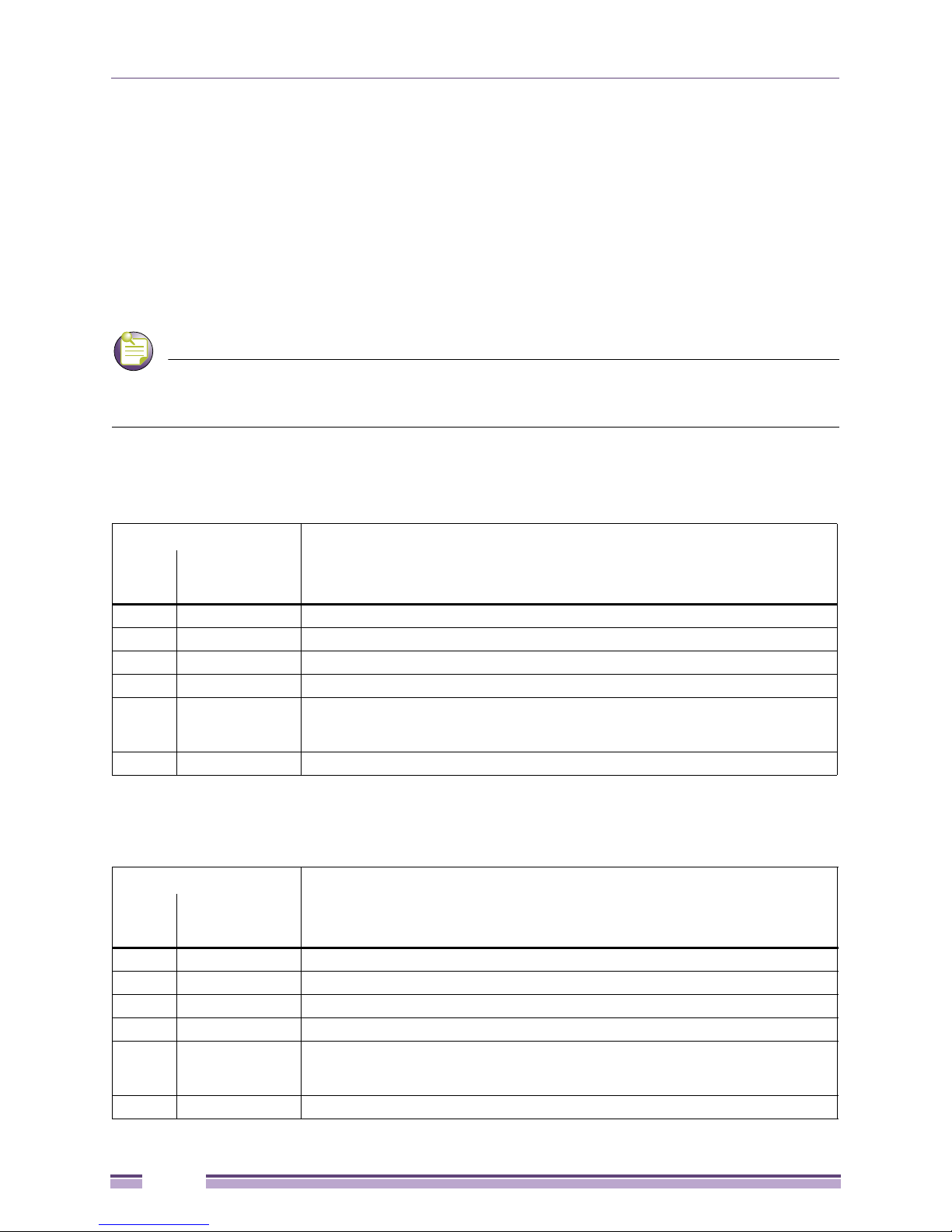
XGM3S-2sf Option Card
The XGM3S-2sf option card (Figure 7) allows you to add one or two 10-Gigabit SFP+ optical ports to
slot A on the rear panel of an E4G-400 router. These ports support synchronous Ethernet and can be
used for stacking connections or data links. The XGM3S-2sf option card supports either SFP+ optical
modules or an SFP+ direct-attach passive copper cable.
Figure 7: XGM3S-2sf Option Card
XGM3S-2xf Option Card
The XGM3S-2xf option card (Figure 8) allows you to add one or two 10-Gigabit XFP optical ports to
Slot A on the rear panel of the E4G-400 router. These ports support synchronous Ethernet and can be
used for stacking connections or data links.
Figure 8: XGM3S-2xf Option Card
E4G Series Routers Hardware Installation Guide
23
CSR_024
1
22
1 = SFP+ ports
2 = LEDs
CSR_026
1 1
32 2
1 = SFP+ ports
2 = LEDs
Chapter 1: About the E4G Series Routers
XGM3SB-4sf Option Card
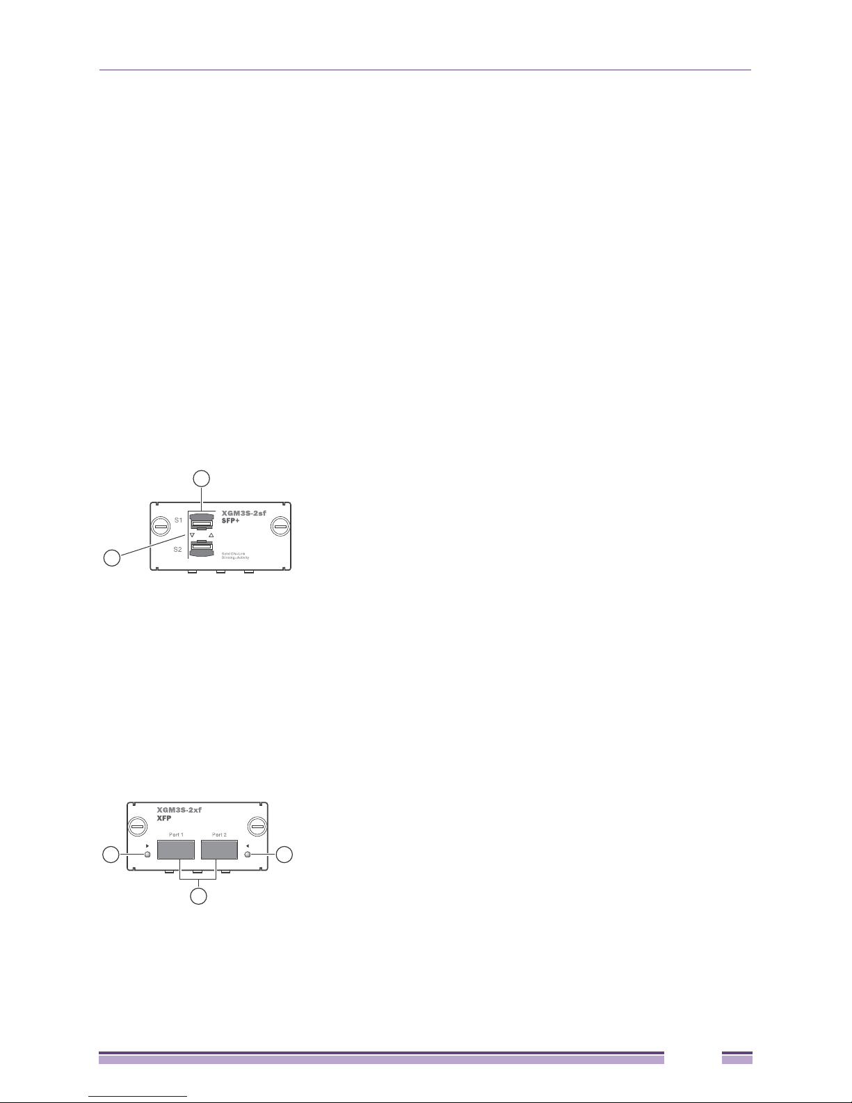
The XGM3SB-4sf option card (Figure 9) allows you to add up to four 10-Gigabit SFP+ optical ports to
Slot B on the rear panel of the E4G-400 router. These ports support synchronous Ethernet and can be
used for data links. The XGM3SB-4sf option card supports either SFP+ optical modules or the SFP+
direct-attach passive copper cable.
Figure 9: XGM3SB-4sf Option Card
E4G-B16T1E1 Option Card
The E4G-B16T1E1 option card (Figure 10) allows you to add 16 T1/E1 ports with pseudowire emulation
to slot B on the rear panel of the E4G-400 router. This option card has two MRJ21 connectors, each one
providing eight ports. Connections to these connectors are made in either of the following ways:
● A special fan-out cable that connects to the module and provides eight separate RJ-45 connectors at
the other end. (See Appendix B for more information about this cable.)
● A straight MRJ21-to-MRJ21 cable that connects to a breakout panel
Figure 10: E4G-B16T1E1 Option Card
24
E4G Series Routers Hardware Installation Guide

Pluggable Interfaces for E4G Series Routers
Pluggable Interfaces for E4G Series Routers
Ports on E4G series routers are compatible with a variety of optical modules, including SFP+ and XFP
modules. Extreme Networks optical modules are tested to work in all supported Extreme Networks
devices. We recommend that all customers use Extreme Networks optical modules in their Extreme
Networks devices. Extreme Networks assumes no liability for third-party optical modules. Although
Extreme Networks does not block third-party optical modules, we cannot ensure that all third-party
optical modules operate properly in all Extreme Networks devices. The customer assumes all risks
associated with using third-party optical modules in Extreme Networks devices.
E4G Series Routers Hardware Installation Guide
25

Chapter 1: About the E4G Series Routers
26
E4G Series Routers Hardware Installation Guide

PA RT
Installing Hardware


NOTE
Site Preparation
2
CHAPTER
This chapter includes the following sections:
● Planning Your Site on page 30
● Meeting Site Requirements on page 30
● Evaluating and Meeting Cable Requirements on page 35
● Meeting Power Requirements on page 41
● Applicable Industry Standards on page 43
By carefully planning your site, you can maximize the performance of your existing network and ensure
that it is ready to migrate to future networking technologies.
The information in this chapter is intended for the system administrator, network equipment technician,
network manager, or facilities manager responsible for installing and managing the network hardware.
The chapter assumes a working knowledge of local area network (LAN) operations, and a familiarity
with communications protocols that are used on interconnected LANs.
Only qualified service personnel should install, maintain, or remove Extreme Networks equipment.
Qualified service personnel have had appropriate technical training and experience that is necessary to
be aware of the hazards to which they are exposed when performing a task and of measures to
minimize the danger to themselves or other people.
Before installing or removing any components of the system, or before carrying out any maintenance
procedures, read the safety information in Appendix A of this guide.
E4G Series Routers Hardware Installation Guide
29

Chapter 2: Site Preparation
Planning Your Site
To install your equipment successfully, you should plan the site carefully. The site planning process has
three major parts:
● Meeting site requirements
The physical installation site must meet the following requirements for a safe and successful
installation:
- Building and electrical code requirements
- Environmental, safety, and thermal requirements for the equipment you plan to install
- Equipment rack requirements
● Evaluating and meeting cable requirements
After examining your physical site and verifying that all environment requirements are met, evaluate
and compare your existing cable plant with the requirements of the Extreme Networks equipment to
determine if you need to install new cables.
● Meeting power requirements
To run your equipment safely, you must meet the specific power requirements for each router and
external power supply unit installed in the system. For power specifications of the router and power
supplies, see the specific router models listed in Appendix B.
Meeting Site Requirements
This section describes requirements to consider when preparing your installation site, and includes the
following topics:
● Operating Environment Requirements (next section)
● Rack and Cabinet Specifications and Recommendations on page 33
● Outdoor Installation Sites on page 35
Operating Environment Requirements
Verify that your site meets all environmental and safety requirements.
Virtually all areas of the United States are regulated by building codes and standards. During the early
planning stages of installing or modifying your network, it is important that you develop a thorough
understanding of the regulations that pertain to your location and industry.
Building and Electrical Codes
Building and electrical codes vary depending on your location. Comply with all code specifications
when planning your site and installing cable. This section lists resources for obtaining additional
information.
For information about major building codes, consult the following organization:
International Code Council (ICC), 5203 Leesburg Pike; Falls Church, Virginia 22041 USA.
http://www.iccsafe.org
http://www.sbcci.org
30
E4G Series Routers Hardware Installation Guide
 Loading...