

Page 1

BETA DRAFT
Altitude 300-2
™
Getting Started Guide
Software Vers ion x.x
Extreme Networks, Inc.
3585 Monroe Street
Santa Clara, California 95051
(888) 257-3000
http://www.extremenetworks.com
Published: Auguest 2003
Part number: XXXX Rev. 01
Page 2

BETA DRAFT
A
E
P
S
©2003 Extreme Networks, Inc. All rights reserved. Extreme Networks and BlackDiamond are registered trademarks of
Extreme Networks, Inc. in the United States and certain other jurisdictions. ExtremeWare, ExtremeWare Vista,
ExtremeWorks, ExtremeAssist, ExtremeAssist1, ExtremeAssist2, PartnerAssist, Extreme Standby Router Protocol, ESRP,
SmartTraps, Alpine, Sum mit, Su mmit1, S ummit4, Summit4/ FX, Sum mit7i, Summit24 , Summi t48, Sum mit Virtual
Chassis, SummitLink, SummitGbX, SummitRPS and the Extreme Networks logo are trademarks of Extreme Networks,
Inc., which may be registered or pending registration in certain jurisdictions. The Extreme Turbodrive logo is a service
mark of Extreme Networks, which may be registered or pending registration in certain jurisdictions. Specifications are
subject to change without notice.
NetWare and Novell are registered trademarks of Novell, Inc. Merit is a registered trademark of Merit Network, Inc.
Solaris is a trademark of Sun Microsystems, Inc. F5, BIG/ip, and 3DNS are registered trademarks of F5 Networks, Inc.
see/IT is a trademark of F5 Networks, Inc.
“Data Fellows”, the triangle symbol, and Data Fellows product names and symbols/logos are
trademarks of Data Fellows.
F-Secure SSH is a registered trademark of Data Fellows.
All other registered trademarks, trademarks and service marks are property of their respective owners.
uthors:
ditor:
roduction:
pecial Thanks:
ii
Page 3

BETA DRAFT
Contents
Introduction 1
Related Publications 2
Conventions 2
Introduction 7
Hardware Description 7
Altitude 300-2TM Models And Connections 7
Radio Characteristics 8
LED Indicators 9
Optional Equipment Not Supplied 10
Software Description 10
Installation Steps 3
Altitude 300-2™ and Mounting Hardware 4
Universal Mounting Bracket 4
T-Bar Fasteners and Spacers 6
Optional Antenna Shrouds 8
Optional Plastic Cover 9
Painting The Plastic Cover 10
Ordering The Plastic Cover Kit 10
External Antennas 10
Placement of the Wireless Port 10
Mounting L ocatio ns 10
Mounting Below A Hard Ceiling 11
Mounting Below A Hanging Ceiling 11
Mounting Above The Hanging Ceiling 11
Mounting O n A Wall 13
Mounting On A Table Or Shelf 13
General Specifications 15
Maximum Number Of Tunable Channels 15
Important No tice 19
FCC - Class B 23
CAUTION STATEMENT:
FCC RF Radiation Exposure Statement 23
Altitude 300-2 Getting Sta rted Guide iii
Page 4

Contents
BETA DRAFT
Industry Canada - Class B 24
European Comm unity 24
Japan 24
iv Altitude 300-2 Getti ng Star ted Guid e
Page 5

BETA DRAFT
Preface
This preface provides an overview of this guide, describes guide conventions, and lists other
publications that might be useful.
NOTE
To ensure proper operation of your Extreme Networks eq uipment, read this guide be fore you install any
Extreme Networks equi pment.
Introduction
This guide provides the required information to in stall the Altitude 300™ wireless port. It also contains
general product information about the Altitude 300-2
This guide is intended for use by net work administrators who a re responsible for installing and setting
up network equipment. It assu mes a basic working knowledg e of:
• Local Area Networks (LANs)
• Ethern et conc epts
• Simple 802.11 wireless LAN con cepts.
See the ExtremeWare Software User Guide for information about configuring an Extreme Networks
device.
NOTE
If the information in the Rel ease Notes that shipped with your switch differs from the in formation in this
guide, follow the Release Notes.
™
.
Altitude 300-2 Getting Sta rted Guide 1
Page 6

Preface
BETA DRAFT
Related Publications
The Extreme Networks wireless port documentation set in cludes:
• Altitude 300-2
• Unified Access Deployment Guide.
• ExtremeWare Software User Guide
Documentation for Extreme Networks products is av ailable on the World Wide Web at the following
location:
http://www.extremenetworks.com/
™
Getting Started Guide (this guide)
Conventions
Table 1 lists conventions that are used throughout this g uide.
Table 1: Notice Icons
Icon Notice Type Alerts you to...
Note Important features or instructions.
Caution Risk of personal injury, system damage, or loss of data.
Warning Risk of severe pe rsonal injury .
Documentation for Extreme Networ ks products is available from the Extreme Networ ks website at the
following location:
http://www.extremenetworks.com/services/documentation/
You can select and download the following Extreme Networks doc umentation from the Doc umentation
section of the Se rvices page :
• Release Notes
• Software
• Hardware
• Reports
• White Papers
• Troubleshooting Tools
• Preventative Maintenance
• Instructional Videos
• Archives
You can also purchase Extreme Networks documentation from the Extreme Networks website.
2 Altitude 300-2 Gettin g Star ted Guide
Page 7

BETA DRAFT
1 Altitude 300-2
Introduction
Introduction
The Altitude 300-2™ wireless dual-band wireless port provides transparent, wireless high-speed data
communications between the Summit 30 0
or mobile devices equipped with 802.11a, and 802.11b/g. wireless adapters.
The Altitude 300-2
Summit 300-48
network. As part of the Unified Access Architecture, the management of Altitude 3 00-2
™
300-48
This integrated network provides unified security, scalability and manageability.
is a seamless extension of Extreme Networks' centralized management system, EPICenter™.
™
is part of Extreme Network's Unified Access Architecture. When connected to the
™
it provides a wireless network that is co mpletely integrated into the enterprise
TM
Wireless Port
™
family of wired LAN products and wireless fixed, portable
™
and Summit
Hardware Description
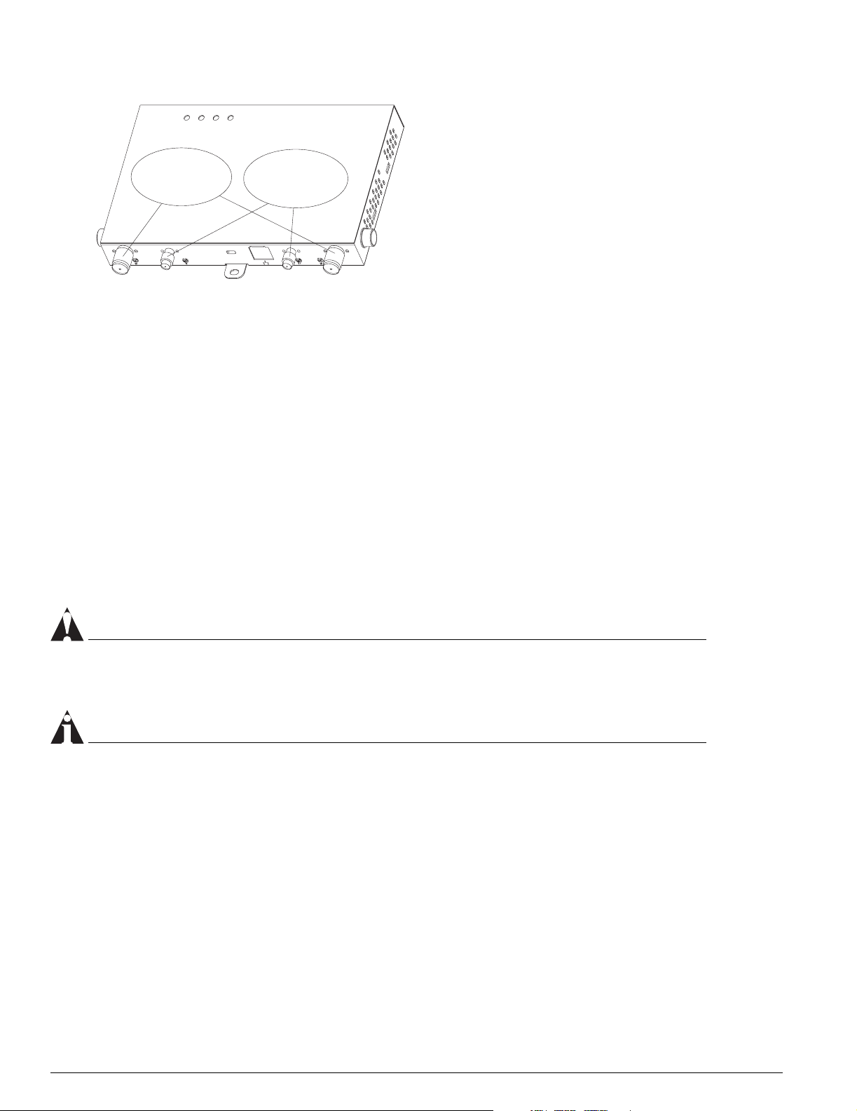
Altitude 300-2TM Models And Connections
The Altitude 300-2™ wireless port box comes in two models. The first, the Altitude-2i™, is a unit with
integrated, dual band antennas and the second, the Altitude-2d
connectors. Both models have the same radios and overall feature set.
2
1
Computer Cable
Padlock
Hole
Figure 1: Rear View Of Altitude 300-2i
Lock Hole
Ethernet
Jack
TM
™
, is a unit with external antenna
Figure 1 shows the rear side o f the
integrated antenna model of the
Altitude 300-2i
plugged into the RJ45 jack. It supplies
both network connectivity and power to
the unit. The Altitude 300-2i
locked by either a standard computer
cable lock inserted in to hole or a
padlock in hole.
™
. The Ethernet cable is
™
can be
Altitude 300-2 Getting Sta rted Guide 7
Page 8
Altitude 300-2TM Wir eless Port I ntroduction
802.11b/g
RP-TNC
Connectors
802.11a
RP-SMA
Connectors
BETA DRAFT
Figure 1 shows the rear side o f the
integrated antenna model of the
Altitude 300-2i
™
. The Ethernet cable is
plugged into the RJ45 jack. It supplies
both network connectivity and power to
the unit. The Altitude 300-2i
™
can be
locked by either a standard computer
cable lock inserted in to hole or a
padlock in hole.
Figure 2: Rear View Of Altitude 300-2d
TM
Radio Characteristics
The Altitude 300-2™ has two radios. The first uses a radio modu lation technique known as Or thogonal
Frequency Division Multiplexing (OFDM). It opera tes in the 5GHz UNII/ISM band s. Data is
transmitted over a half-duplex radio channel operating at up to 54 Megabits per sec.
The second radio has two modulation modes both using half-duplex access. The first modula tion mode,
Direct Sequence Spread Spectrum (DSSS) is used with 802.11b clients. It operates up to 11 Mbps. The
second modulation, OFDM is used with 802.11g clients. Like 802.11a it operates up to 54 Mbps. These
modulations use the 2.4 GHz, ISM band . In the ISM band the Altitude 300-2
present and selects the modulation mode.
Both UNII band and ISM band radios support antenna diversity. The Altitude 300-2i
integrated antennas. These antennas are dual band, operating simultaneously in the 2.4 - 2.4835 GHz
and 5.15- 5.35 and 5.725 - 5.85 GHz bands. The Altitude 300-2d
™
has external antenna connectors that
that support attachable antennas that operate in the 2.4 - 2.4835 GHz and 5.25 - 5.35 and 5.725 - 5.85
GHz bands.
CAUTION
External antenn as must be cer tified by Extreme Networks or sel ected by a profession installer to insure
they meet all regulator y requirements.
™
detects what clients are
™
has two
NOTE
The Altitude 300-2dTM is designed for diversity with two antenn a connectors for each radio. It is impor t
for the proper operation of the wirele ss port tha t antennas be insta lled on each connector.
8 Altitude 300-2 Gettin g Star ted Guide
Page 9
BETA DRAFT
Hardware Description
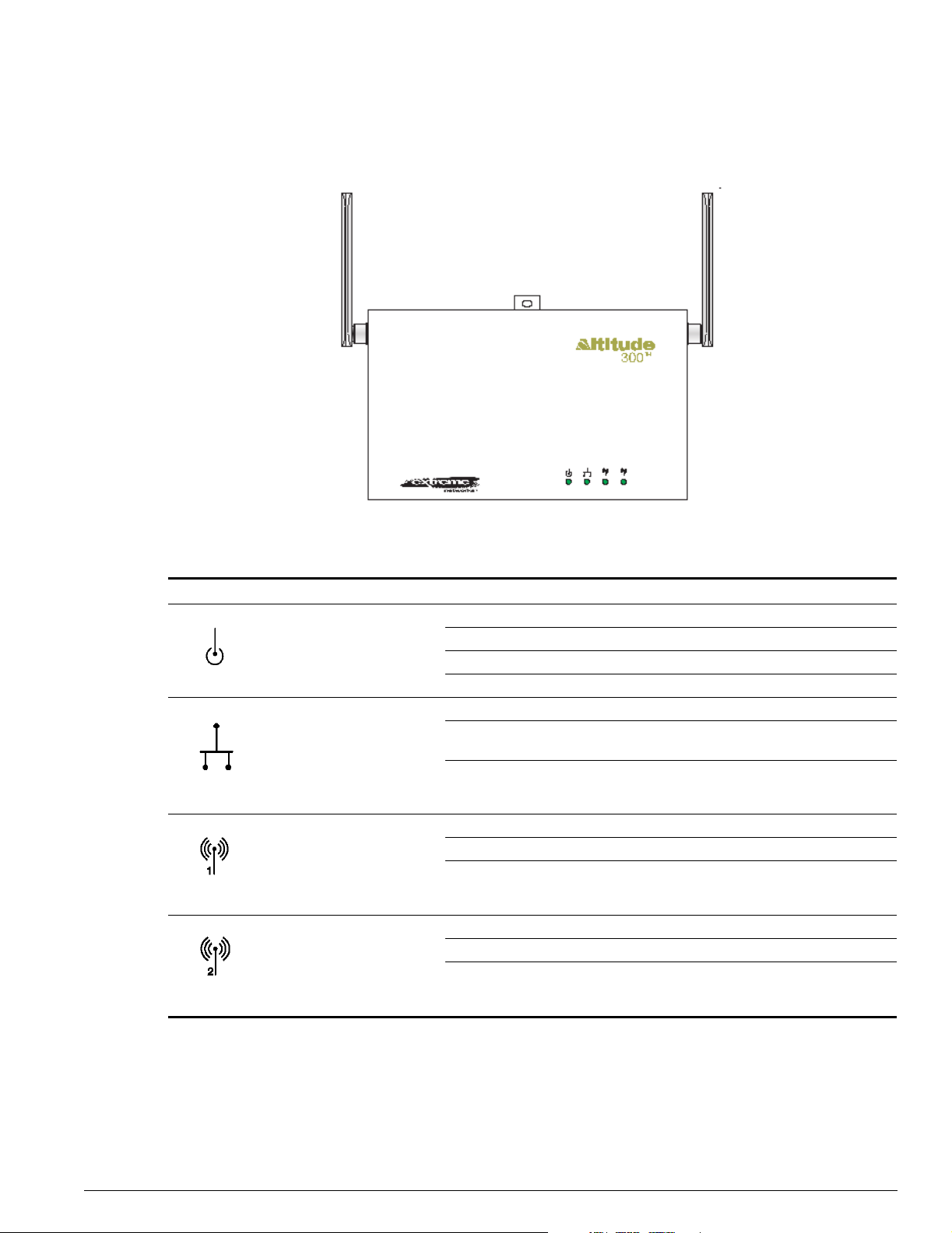
LED Indicators
The Altitude 300-2™ includes four status LED indicators visible on the basic bo x or through the light
pipes of the plastic cover. They are depicted and described in the Figure 3 and Table 1.
TM
Figure 3: Altitude 300-2
LED Indicators, Without Plastic Cover
Table 2: LED Indicator Functions
LED Symbol LED Name Color Status Description
Power Amber
&
Green
LAN Green Off No Ethernet link or the link is disabled
Radio 1 Green Off Disabled or no BSS constructed
Radio 2 Green Off 802.11b/g Disabled or no BSS constructed
Off No power
Amber On Self test fault found
Green Flashing Indicates loading software program
Green On The unit is operational.
On Indicates a valid 10/100 Mbps Ethernet cable
link.
Flashing Indicates that the wireless port is transmitting or
receiving data on a 10/100 Mbps Ethernet LAN.
Flashing rate is proportional to the link's activity.
On 802.11a BSS constructed and no activity
Flashing Indicates that the wireless port is transmitting or
receiving data through the 802.11a radio.
Flashing rate is proportional to network activity.
On 802.11b/g BSS constructed and no activity
Flashing Indicates that the wireless port is transmitting or
receiving data through the 802.11b/g radio.
Flashing rate is proportional to network activity.
Altitude 300-2 Getting Sta rted Guide 9
Page 10

Altitude 300-2TM Wir eless Port I ntroduction
Figure 4: Package Checklist
™
The Altitude 300-2
wireless port package includes:
BETA DRAFT
• One Altitude 300-2
™
wireless port (Altitude 300-2i™ or Altitude 300-2d™)
• One short Ethernet straight cable
• Altitude 300-2
™
Getting Started Manual
• One universal mounting bracket
• Two T-Bar ceiling fasteners and fastener nuts
• Two T-Bar fastener spacers
• Four #8x1 inch (25.4 mm) m ounting screws and plastic a nchors
• Four stick-on feet
• One cable tie to secure the Altitude 300-2O to the universal mounti ng bracket
• One 10-24 nut
The optional plastic cover kit not included here contains:
• Five Altitude 300-2
• Ten antenn a shrouds for use with the Altitude 300-2i
™
plastic covers (15482- translucent, 15483- cool gray, 15484- cream).
™
.
• An installation guide sheet.
If possible, retain the carton, including the origi nal packing materials. Use them again to repack the
product in case there is a need to return it.
Optional Equipment Not Supplied.
• One padlock for securing the Altitude 300-2
™
to the universal mounting bracket. The lock hasp i s
compatible with a Master Lock 120T lock or a like mode l.
WARNING!
The Altitude 300-2™ is not secured to the b racket unless a padlock is used. If a padlock is no t used
the unit should be se cured to the bracket by a cable tie through the lock hasp to keep it from falling.
Failure to secure the unit is hazardou s.
• One computer lock cable for securing the Altitude 300-2
™
when the universal mounting bracket is
not used.
• Box hanger for installing the Altit ude 300-2
• External antenna(s) for the Altitude 300-2d
™
above the tiles of a suspended ceiling.
™
. Extreme Networks' external antennas can be
ordered separately.
Software Description
The Altitude 300-2™ receives its software and conf iguration from the Summit 300™ switch. A description
of the software and the wireless port's configuration is in the Sum mit 300
™
manual.
10 Altitude 300-2 Getti ng Star ted Guid e
Page 11

BETA DRAFT
2 HARDWARE INSTALLATION
Installation Steps
1 For wall and ceiling i nstallation s the universal moun ting bracket i s used. If unit is being mounted on
a table or shelf skip to step 4. Locate and install the universa l mounting bracket. Refer to the
instructions for the various ceiling in stallation options (Moun ting Below A Hard Ceiling page 18,
Mounting Below A Hanging Cei ling: page 18, Mounting Above The Hanging Ceiling: page 18, and
Mounting Above The Hanging Ceiling: page 19) and the wall mou nting option (Mounting On A Wall:
page 20) in the next section.
2 Mount the Altitude 300-2
mounting holes on the back of th e unit. The mounting stu ds on the universal mounting brac ket fit
into the slotted mounting holes. Th e unit slides all the way forward into these holes. The lock hasp
hole on the Altitude 300-2
bracket when the unit is slid all the way forward, see Figure 5: Mounting The Wireless Port On The
Universal Mounting Bracket on page 1 4.
3 Lock and secure the Altitude 300-2
designed to use a Master Lock 120T or similarly sized padlock to secure the wireless port from theft
of from coming off the bracket, see Figure 5: Mounting The Wireless Port On The Universal
Mounting Bracket on pag e 14. Wall and ceiling installa tions skip step 4.
™
on the universal mounting bracket. The Altitude 300-2™ has three slotted
™
should line up with the lock h asp hole on the universal mounti ng
™
. The Altitude 300-2™ and the universal mounting bracket are
WARNING!
The Altitude 300-2™ is not secured t o the bracket unless a padl ock is used. If a pad lock is not used the
unit should be secured to the bracket by a cable tie through the lock hasp to keep it from falling. Failure
to secure the unit is haza rdous.
4 For table and shelf installations, attach the s tick-on feet. The Altitude 300-2
stick-on feet for use when the unit is installed on top of a table or shelf. The feet do not have to be
used for wall and ceiling installations.
WARNING!
The stick-on feet have not been tested for use in a plenum space. Do not use them for above the ceiling
installations.
5 Connect the Ethernet Cable - The Altitude 300-2
cable from a Summit 300-48
Altitude 300-2 Getting Sta rted Guide 3
™
.
™
is connected to a powered, 10/100BaseT Ethernet
™
kit comes with four
Page 12

HARDWARE INSTALLATION
NOTE
BETA DRAFT
While the Altitude 300-2™ uses standard a standar d 10/100BaseT signal and PoE power, it should only
be connected to a Summit 300-48
™
port for the proper ope ration of the management a nd configuration
features of Extreme Networks’ Unified Access System.
™
6 Connect the computer cable lock (optional). When the Altitude 300-2
universal mounting bracket, the unit can be locked with a computer cable. The Alt itude 300-2
installation does not use the
™
has a
standard computer cable lock hole located at the rear of the box, see Figure 1: Rear View Of Altitude
™
300-2i
7 Connect the external antennas, Altitude 300-2d
Altitude 300-2dO has connectors for external antennas, see Figure 2: Rear View Of Altitude 300-2d
on page 7, or Figure 2: Rear View Of Altitude 300-2d™ on page 8.
™
. For the Altitude 300-2i™ skip to step 8. The
™
on page 8. The access unit should be located wi thin the reach of the antenna's cables. The large
RP-TNC connectors are used for 2.4 GHz 802.11b/g antennas and the small RP-SMA connectors for 5
GHz 802.11a antennas. Two connectors of each type are supplied to support spatial diversity. The
unit can be operated with one antenna on each radio if desired. When this step is completed go to
step 10.
8 Attach the antenna shrouds (Altitude 300-2i
™
) - If the plastic cover is going to be used attach the
antenna shrouds to the antennas, see Figure 8: Antenna Shroud on page 16.
9 Adjust the Integrated antennas, Altitude 300-2i
™
- The Altitude 300-2i™ is equipped with two
integrated dual band antennas that connect to both the 802.11a and 802.11b/g radios. Selecting the
proper angle for the antennas is important to achieve the best performance from the system. For this
reason the Altitude 300-2i
been set the Altitude 300-2i
™
is equipped with antennas that can be rotated. Once the proper angle has
™
is outfitted with antenna shrouds that work with the plastic cover to
lock in the proper angle. This to prevents the antennas from being accident ally misaligned after
installation.
10 Attach the plastic cover -Attach the optional plastic cover to the box, see Figu re 10: Plastic Cover
Installation on page 17. After the cover has been secured push on each antenna to make sure is
shroud is locked in position. This ensures that the teeth on the shroud are engaged with the teeth on
the cover.
WARNING!
Attach the plastic cover -Attach the optional plastic cover to the box, see Figure 1 0: Plastic Cover
Installation on page 17. After the cover has been secured push on each antenna to make su re is
shroud is locked in position. This ens ures that the teeth on the s hroud are engaged with th e teeth on
the cover.
Altitude 300-2™ and Mounting Hardware
Before starting to install the wireless port and its hardware, take time to become famil iar with the parts
and their physical features.
Universal Mounting Bracket
The universal mounting bracket included wi th the wireless port is designed to mount on vertical and
horizontal surfaces like w alls and ceilings. It can be attached to electrical junction boxes in place of a
wall plate and the Ethernet cable routed from the wall or ceiling through the central hole in the bracket
to the Altitude 300-2
solid surface and the Ethernet cable attached through the network cable hole in the rear of the plastic
4 Altitude 300-2 Gettin g Star ted Guide
™
’s Ethernet jack. The universal mounti ng bracket can also be directly att ached to a
Page 13

BETA DRAFT
cover. The universal mounting bracket is also used for installations where the Altitude 300-2™ is placed
in the plenum area above a hanging ceiling. For these locations it is designed to connect to a box hanger
bar that is attached to the ceiling’s T-Bars.
Mounting Stud (x3)
Front View Wall View
Padlock Hole
Cable Hole
Cable Tie (x2)
10-24 Threaded
Grounding Stud
Various Mounting
Holes
Figure 5: Universal Mounting Bracket
There are a number of holes and other features on the universal mounting bracket. The large central
hole is for passing cables through when co nnecting the wireless port to in-the-wall cables . The smaller
holes are designed to mate w ith various fastening ha rdware like junction boxes and box han ger bars.
Two cable tie loops are provided for dressing cables. They accept standard nylon cable ties. The
threaded stud is provided for grounding the plate when electrical codes require it. The lock hasp lines
up with the lock hasp on the Altitude 300-2
™
. It secures the wireless port to the bracket. Either a lock or
a cable tie can be placed in the lock holes.
™
To mo unt the Altitude 300-2
on the bracket, place the box's mounting holes over the mounting studs
on the bracket. Firmly slide the wireless port along the mounti ng studs until the holes in the lo ck hasps
line up. The unit is designed to snap into place so some force is required.
WARNING!
Make sure the holes in th e lock hasps are lined up to ensure that the wirele ss port i s completely
seated. Also make sure tha t the wireless por t is engaged on all three mounting s tuds.
Altitude 300-2 Getting Sta rted Guide 5
Page 14

HARDWARE INSTALLATION
(2) Insert the bracket’s
mounting studs into the
mounting holes
(3) Firmly slide the
box down on the studs
BETA DRAFT
(1) Locate the three mounting
holesonthebackofthebox
(4) The box is properly
installed when the lock
hasp holes are lined up
Figure 6: Mounting The Wireless Por t On The Universal Mounting Bracket
To remove the wireless port from the universal mounting bracket first unlock or remove the cable tie.
Push the box in the direction of the lock hasp wh ile gently lifting it away from the bracket.
The universal mounting bracket is part of the Altitu de 300-2
™
kit. Spares may also be ordered. The part
number is 15921.
T-Bar Fasteners and Spacers
The T-Bar fasteners included with the wireless port are designed to connect to a range of hanging
ceiling T-Bar sizes. Following the steps in Figure 6, spread the T-Bar fastener apart, place it on the T-Ba r
and squeeze it together until it is firmly seated on the T-Bar. With the two T-Bar fasteners in place and
properly spaced to match the brackets T-Bar fastener holes, determine if spacers are needed. The T-Bar
fastener spacers are designed for hanging ceilings where the ceiling tiles' bottom surface is bellow the
T-Bar. If this is the case, insta ll the spacer as show in the diagram. The spacer allows the universal
mounting bracket to sit below th e bottom surface of the ceiling tile.
The universal mounting bracket is insta lled using the large wing nuts provided. Make sure these w ing
nuts are tight.
6 Altitude 300-2 Gettin g Star ted Guide
Page 15

BETA DRAFT
WARNING!
For safety it is recommended that two T-Bar fastene rs be used to connect the Al titude 300-2™ to a
hanging ceiling. Make sure th at the fasteners are securely on the T-Bar before installing the un iversal
bracket and wireless port.
Downward face of the
T-Bar
(A)
Swing the arms
together to attach the
T-Barfastenertothe
(B)
T-Bar
Mount the bracket on the
T-Bar fasteners and secure
it with the T-Bar nuts
Figure 7: Installation On A Hanging Ceiling
The universal mounting bracket has mounting holes tha t allow it to be in stalled inline with t he T-Bar as
shown in Figure 6 or at right angles to the T-Bar.
Some hanging ceilings have ti les with bottom surfaces t hat hang bellow the bottom of the T-Bar. For
these ceilings spacers are provided. The spacers go between the T-Bar fasteners and the universal
mounting bracket as sho wn in Figure 7.
Altitude 300-2 Getting Sta rted Guide 7
Page 16

HARDWARE INSTALLATION
Downward face of
the T-Bar
Optional spacer
Figure 8: Installation Of Optional Spacer
BETA DRAFT
NOTE
Use a small piece of tap e to hold the spacer in plac e on the universal mounting bracket and instal l the
spacer and the bracket together.
Optional Antenna Shrouds
Antenna shrouds are used with the Altitude 300-2i™ that has integrated dual band antennas. They are
an optional item that is ordered with on e of the plastic cover kits . Before the plastic cover is snapped
on, each antenna shroud is slipped over the antenna hous ing so that the gear teeth are next to the box.
The shroud is slipped all the way down on the antenna housing until it is firmly seated on the antenna
tube that comes out of the box. The shroud clips on to the tube. With the shroud installed, the antenna
is still free to be rotated to the desired angle. The process is repeated for the other side of the box.
1
2
Figure 9: Antenna Shroud Figure 10: Antenna Shroud Installation
8 Altitude 300-2 Gettin g Star ted Guide
Page 17

Optional Plastic Cover
BETA DRAFT
The plastic cover is used with either the Altitude 300-2i™ or Altitude 300-2d™. Plastic covers are
optional an d are ordered with the plasti c cove r kit. The cover is in stalled on the Altitude 300 -2
™
after all
cable connect ions and ant enna adjustm ents are made and after th e unit is locked or secured. To install
the plastic cover place it directly over the box and line up the antenna slots in the cover with the
antenna tubes on the box. While gently pu lling out on the s ides of the case where the clips are, press the
cover firmly on to the box. The installer should hear and feel the cover snap into position.
Mount the bracket, and connect the
padlock and any cables before installing
the plastic cover
Gently pull out on the
sides of the plastic cover
as it is installed on the
1
2
box
Figure 11: Plastic Cover Installation
NOTE
The cover is designed to secure the Altitude 300-2™ from casual tamper ing that can affect ser vice to
the clients. With the case in place the unit can’t be unlocked, the Ethernet con nection can't be
unplugged, the integrated a ntennas (Altitude 300-2i
connections (Alti tude 300-2d
™
) can't be undone.
™
) can't be rotated and the exter nal antenna
To remove the plastic cover, gently pull the sides near the clips outwards while pulling the cover off the
box.
Altitude 300-2 Getting Sta rted Guide 9
Page 18

HARDWARE INSTALLATION
BETA DRAFT
Painting The Plastic Cover.
The plastic cover can be painted to match a decor with any paint that is suitable for poly carbonate
plastic. The plastic light pipe must be removed before painting. The light pi pe assembly can be gently
popped off using a screwdriver that is slipped into the small lips provided on the light pipe. After
painting, reinstall the light pipe by snappin g it back in place.
NOTE
Painting the antennas is not recommen ded.
Ordering The Plastic Cover Kit.
The plastic cover kit may be order from Extreme Networks. The kit includes covers and antenna
shrouds. Please consult the Extreme Networks product web site, www.extremenetworks.com, for the
latest product information. The plastic cover kits offered include:
Product Number: 15434- five translucent covers and ten black antenna shrouds
Product Number: 15435- five cool gray covers and ten black antenna shrouds
Product Number: 15436- five cream covers and ten black antenna shrouds
External Antennas
The Altitude 300-2d™ uses external antennas. Consult the Extreme Networks product web page for a
current list of available external antennas. External antennas are connected to the RP-TNC connectors
for the 802.11b/g radio and to the RP-SMA connectors for the 802.11a radio. The external antennas are
connected before the optional plastic cover is installed.
NOTE
The Altitude 300-2d™ is designed for diversity with two antenna c onnectors for each radio. It is impor t
for the proper operation of the wirele ss port tha t antennas be insta lled on each connector.
Placement of the Wireless Port
Choose a proper place for the wireless port. In general, the best location is at the center of the wireless
coverage area, within line of sight of as many as possible wireless devices. Try to place the wireless port
in a position that can best covers its cell. Normally, the higher the wireless port is placed, the better the
overall performan ce.
Mounting Locations
The Altitude 300-2™ and its mounting hardware are designed for insta llation in a variety of places
inside a building. The ins tallation site ma y be selected for any combination of RF performance,
aesthetics, an d convenien ce reasons.
10 Altitude 300-2 Getti ng Star ted Guid e
Page 19

BETA DRAFT
WARNING!
The Altitude 300-2™ is not designed for outdoor us e or sites that exceed its environmen tal
specifications.
Mounting Below A Hard Ceiling
The Altitude 300-2™ may be installed underneath a ha rd ceiling where wall anchors are used to mount
the bracket. Select the orientation for the bracket remembering that that integrated antennas are on the
side and to the back of the Altitude 300-2i
ceiling. For each of the four plastic anchors supplied with the un it, drill 4.8 mm (3/16"} pilot holes, 24 .5
mm (1") deep. If wall anchors are not being used drill 3.2 mm (1/8") holes, 1 inch (25.4 mm) deep.
Install the bracket using the screws from the kit. The Altitude 300-2
mounting slots on the bracket and sli de all the way to the front, see Figure 5: Mounting The Wireless
Port On The Universal Mounting Bracket on page 14. The unit should then be secured with either a
padlock (not supplied) or a cable tie (sup plied). The installer may now follow the standard instructions
for connecting the Ethernet cable, antenna shrouds for integrated antennas, and the plastic cover.
™
. Use the bracket as a template to mark the ho les on the
™
is designed to slip into the
WARNING!
The Altitude 300-2™ is not secured t o the bracket unless a padl ock is used. If a pad lock is not used the
unit should be secured to the bracket by a cable tie through the lock hasp to keep it from falling. Failure
to secure the unit is haza rdous.
Mounting Below A Hanging Ceiling
The Altitude 300-2™ may be suspended from the T-Bars of a hanging ceil ing. The mounting kit contains
two T-Bar fasteners that can be adjusted for a variety of T-Bar widths. There are a number of round
holes on the bracket that can be used for the T-Bar fasteners; use two that are convent for the required
orientation on the ceiling. The bracke t is oriented on the T-Bar with so that the antennas f ace the desired
direction. Use the bracket to lightly mark where the T-Bar fasteners should be placed. Install the two
T-Bar fasteners on the T-Bar, see Figure 6: Installation On A Hanging Ceiling on page 1 5. Some ceilings
have ceiling tiles that hang down below the bottom of the T-Bar. Spacers are provided with the kit for
these types of tiles. The spaces go between the T-Bar fasteners and the bracket with the spacer's face
against the bracket, see Figure 7: Installa tion Of Optional Spacer on page 15. Mount the bracket and
make sure fasteners are tight and the bracket is secure. The Altitude 300-2
bracket's mounting slots an d slid all the way to the back, see Figure 5: Mounting The Wireless Port On
The Universal Mounting Bracket on page 14 . The unit should th en be secured with either a padloc k (not
supplied) or a cable tie (supplied). The install er may now follow the standa rd instructions for
connecting the Ethernet cable, antenna shrouds for integrated antennas, and the plastic cover.
WARNING!
™
is now slipped into the
The Altitude 300-2™ is not secured t o the bracket unless a padl ock is used. If a pad lock is not used the
unit should be secured to the bracket by a cable tie through the lock hasp to keep it from falling. Failure
to secure the unit is haza rdous.
Mounting Above The Hanging Ceiling
The Altitude 300-2d™ is compliant with UL 20 43 for installation in t he plenum area above a hanging
ceiling. The installer needs to make su re that the Ethernet cable used to connect to the unit is also
Altitude 300-2 Getting Sta rted Guide 11
Page 20

HARDWARE INSTALLATION
.
BETA DRAFT
plenum rated, see the National Electric Code, NEC, Section 300-22(C). Equipment a bove the hanging
ceiling should be secured to the T-Bars using a box hanger (not supplied). The universal m ounting
bracket has been designed to work with box hangers such as those from B-Line or Caddy, see Figure 11:
Above The Ceiling Box Hanger Mount on page 20.
Examples of these T-Bar box hangers pro ducts are:
B-Line model: BA50A, www.cooperbline.com
Caddy model: 512-BU, www.erico.com
External antennas are recommended for installations above the ceiling. Locate where the external
antenna will be located and their orien tation. Select a site above the ceilin g for the Altitude 300-2d
™
.
This should be within reach of the external antenna’s cables. Install the box hanger following the
manufacturer's instructions. If the box hanger comes with a box the universal bracket ca n be installed
onto the box or the box can be taken off and the bracket can be ins talled directly onto the box hanger
bar using the fastener provided by the manufacturer. Make sure all the fasteners are tight before
mounting the Altitude 300-2
™
on the bracket. The Altitude 300-2™ should be secured to the bracket
using either a padlock or a cable tie.
WARNING!
The Altitude 300-2™ is not secured t o the bracket unless a padl ock is used. If a pad lock is not used the
unit should be secured t o the bracket by a cable tie through the lock hasp to keep it from falling. Failure
to secure the unit is ha zardous.
Connect the external antenna cables and the powered Ethernet cable to the Altitude 300-2d
™
.
WARNING!
The plastic cover and the an tenna shro uds have not been tested for use in a plenum space. Do not us e
them for above the ceiling installations.
Box Hanger
Bracket
Typical
Adjustable Box
Hanger
The box hanger is
not supplied by
Universal
Extreme Networks
Mounting
Bracket
Hanging
Fasteners
Ceiling
T-Bars
Figure 12: Above The Ceiling Box H anger Mount
12 Altitude 300-2 Getti ng Star ted Guid e
Page 21

BETA DRAFT
Mounting On A Wall
The Altitude 300-2™ can be mounted on a vertical surface using the universal mounting bracket
supplied. The vertical position sho uld be with the Ethernet cable and lo ck hasp pointing up. Select the
location for the unit and use the bracket as a templa te to mark the holes in the ceiling. For each of the
four plastic anchors supplied with t he unit, drill 4.8 mm (3/16”} pi lot holes, 24.5 mm (1”) deep. If wa ll
anchors are not being used drill 3. 2 mm (1/8”) holes , 1 inch (25.4 mm) deep . Install the bracket using
the screws from the kit. The Altitude 300-2
and slide all the way down, see Figure 5: Mounting The Wireless Port On The Universal Mounting
Bracket on page 14. The unit should then be secured with either a padlock or a cable tie. The installer
may now follow the standard instructions for connecting the Ethernet cable, antenna shrouds for
integrated antennas, and the plastic cover.
™
is designed to slip into the mou nting slots on the brac ket
The Altitude 300-2
™
is not secured to the bracket unless a padlock is us ed. If a padlock is not used the
unit should be secured to the brack et by a cable tie through the lock ha sp to keep it f rom falling. Failure
to secure the unit is hazardous.
Mounting On A Table Or Shelf
The Altitude 300-2™ can be installed on a table or shelf us ing the stick-on feet supplied in t he unit's kit.
After the feet are applied, the unit is placed on the horizontal surface and the powered Ethernet cable
attached. If the unit is to be locked a standard computer cable and lock can be used. The computer lock
hole is located at the rear of the Altitude 300-2
The antennas are installed and the antennas are adjusted now for optimal performance. After that the
plastic cover is attached, securing the antennas and Ethernet cable.
™
, see Figure 1: Rear View Of Altitude 300-2i™ on page 7.
Altitude 300-2 Getting Sta rted Guide 13
Page 22

HARDWARE INSTALLATION
BETA DRAFT
14 Altitude 300-2 Getti ng Star ted Guid e
Page 23

BETA DRAFT
A SPECIFICATIONS
General Specifications
Maximum Number Of Tunable Channels
802.11a
FCC/IC: 13
ETSI: 4
France: 8
Spain: 8
MMK: 4
802.11b
FCC/IC: 1-11(3 non-overlapping)
ETSI: 1-13 (3 non-overlapping)
France: 10-14 (2 non-overlapping)
Spain: 10-11 (1 non-ov erlapping)
MKK: 1-14 (4 non-overlapping)
Data Rate
802.11a: 6, 9, 12, 18, 24, 36, 48, 54 Mbps per channel
802.11b: 1, 2, 5.5, 11 Mbps per channel
802.11g: 6, 9, 12, 18, 24, 36, 48, 54 Mbps per channel
Operating Frequency
802.11a
5.15 ~ 5.25 GHz (lower UNII band) US/Canada (Altitude 300-2dO only), Japan
5.25 ~ 5.35 GHz (middle UNII band) US/Canada
5.725 ~ 5.825 GHz (upper UNII and ISM C band) US/Canada
802.11b/g
2.4 ~ 2.4835 GHz
Altitude 300-2 Getting Sta rted Guide 15
Page 24

SPECIFICATIONS
BETA DRAFT
Maximum Output Power
(Note that the maximum allowable setti ng varies with individual country regulations)
802.11a
5.15 ~ to 5.25 GHz: 16 dBm
5.25 ~ to 5.35 GHz: 19 dBm
5.725 ~ to 5.85 GHz: 19 dBm
802.11b
17 dBm
802.11g
15 dBm
Radio Configurations
Dual band: 2.4 GHz ISM and 5 GHz UNII/ISM
Dual channel: one 802.11a and one 802.11b/g
Number of Clients
Greater than 256
Network Configuration
Infrastructure
Power supply
Power Over Ethernet (PoE) Standard: IEEE 802.3af
11 watts when both channels are o perating
Physical Size With Plastic Cover
21.3 (wide) x 16 (deep)x 4 (high) cm, (8.4 x 6.3 x 1.6 in)
Mounting bracket adds 2 cm (0.8 in) to the height
Weight
635 grams (22.4 oz)
Add 20 grams (0.71 oz) for the mounting bracket
LED Indicators
Ready (Power On/Fault), LAN (Ethernet Link/Activity), WLAN1 -802.11a and WLAN2 -802.11b/g
(Wireless On/Activity)
Network Management
EPICenterO
Temperature
Operating: 0 to 55 oC (32 to 131 oF)
Storage: 0 to 70 oC (32 to 158 oF)
Humidity
5% to 95% (non -condensing )
16 Altitude 300-2 Getti ng Star ted Guid e
Page 25

Emissions
FCC Part 15.107 and 15.109 (C1ass B)
IECS-003 (Canada)
VCCI (Japan)
EN 301.489-1 and -17 (Europe)
Safety
CSA 22.2 No. 950-95
UL 1950 UL 20 43
EN60950
IEC60950
Radio Approvals
FCC Part 15.247, 15.401-15.407
RSS-139-1, RSS-210 (Canada)
EN 301.893, 300.328 (Europe)
ARIB STD-T71, Telec 33B (Japan)
AS 4268.2 (Australia)
AS/NZS 354B (Australia and New Zealand)
BETA DRAFT
General Specifications
Standards
IEEE 802.3 10BASE-T, IEEE 802.3u 100BASE-TX
IEEE 802.11a/b/g
IEEE 802.3af
FCC Bulleting OET-65C
RSS-102
Wi-Fi member
Sensitivity
Table 3: 802.11a Radio
Modulation/Rates Sensitivity (dBm)
BPSK (6 Mbps) -88
BPSK (9 Mbps) -87
802.11a Rad io -86
QPSK (18 Mbps) -84
16 QAM (24 Mbps) -81
64 QAM (48 Mbps) -77
64QAM(54 Mbp s) -69
Altitude 300-2 Getting Sta rted Guide 17
Page 26

SPECIFICATIONS
Table 4: 802.11b/g Radio
Modulation/Rates Sensitivity (dBm)
DSSS-DBPSK (1Mbps) b -91
DSSS-DQPSK (2 Mbps) b -88
CCK-DBPSK (5.5 Mbps) b -87
CCK_DQPSK (11 Mbps) b -85
BPSK (6 Mbps) g -89
BPSK (9 Mbps) g -88
BPSK (9 Mbps) g -87
QPSK (18 Mbps) g -85
16 QAM (24 Mbps) g -82
16 QAM (36 Mbps) g -79
64 QAM (48 Mbps) g -74
64QAM(54 Mbp s) g -71
BETA DRAFT
18 Altitude 300-2 Getti ng Star ted Guid e
Page 27

BETA DRAFT
B Maximum Distance Table
Impor tant Notice
Maximum di stances p osted belo w are actual tested dist ance thres holds for t he Altitu de 300-2i™ with
integrat ed ante nna. Ho wever, there are many variab les such as barrier composition and construction
and local environmental interference that may impact your actual distances and cause you to experience
distance thresholds far lower than those we post below.
Table 5: 802.11a Maximum Distanc es
802.11a Wireless Products Maximum Distance Table, Integrated Antenna
Speed and D istance R anges
EnvironmentalCondition 54 Mbps 18 Mbps 6 Mbps
OutdoorEnvironment
IndoorEnvironment
1. Outdoor Environment: A line-of-sight environment with no interference or
obstruction between the wireless port and clients.
2. Indoor Environment: A typical office or home environment with floor to
ceiling obstructions between the wireless port and clients.
1
31 m
(100 ft)
2
18 m
(60 ft)
168 m
(550 ft)
46 m
(150 ft)
335 m
(1100 ft)
64 m
(210 ft)
Table 6: 802.11b Maximum Distanc es
802.11b Wireless Products Maximum Distance Table, Integrated Antenna Speed
and Distance Ranges
EnvironmentalCondition 11 Mbps 5.5 Mbps 2 Mbps 1 Mbps
OutdoorEnvironment
IndoorEnvironment
1. Outdoor Environment: A line-of-sight environment with no interference or
obstruction between the wireless port and clients.
2. Indoor Environment: A typical office or home environment with floor to
ceiling obstructions between the wireless port and clients.
1
137 m
(450 ft)
2
49 m
(160 ft)
238 m
(780 ft)
238 m
(780 ft)
305 m
(1000 ft)
103 m
(340 ft)
488 m
(1600 ft)
152 m
(500 ft)
Altitude 300-2 Getting Sta rted Guide 19
Page 28

Maximum Distance Table
BETA DRAFT
Table 7: 802.11g Maximum Distances
802.11g Wireless Products Maximum Distance Table, Integrated Antenna
Speed and Distance Ranges
EnvironmentalCondition 54 Mbps 18 Mbps 6 Mbps
OutdoorEnvironment
IndoorEnvironment
1. Outdoor Environment: A line-of-sight environment with no interference or
obstruction between the wireless port and clients.
2. Indoor Environment: A typical office or home environment with floo r to
ceiling obstructions between the wireless port and clients.
1
34 m
(110 ft)
2
20m
(65ft)
104 m
(340 ft)
46 m
(150 ft)
198 m
(650 ft)
61 m
(200 ft)
20 Altitude 300-2 Getti ng Star ted Guid e
Page 29

BETA DRAFT
C Integrated Dual Band Antenna Pattern
The Altitude 300-2i™ has two integrated dual band antennas. The characteristics of the antennas are
given in the tables and figures below.
Table 8: Integrated Antenna El ectrical Specifi cation
Frequency range 2.4 GHz - 2.5 GHz 5.12 GHz 1 5.875 GHz
1
Gain
Polarization Linear, vertical Linear, vertical
1. Exclusive of internal cable loss: for 5 GHz band, 0.8 dB; for 2.4 GHz band, 0.5 dB.
1.5 dBi 4.5 dBi
Figure 13: Antenna Radiation Patterns Figure 14: Integrated
Altitude 300-2 Getting Sta rted Guide 21
Page 30

Integrated Dual Band A ntenna Patter n
BETA DRAFT
Figure 15: Antenna Radiation Pattern Reference Diagram
22 Altitude 300-2 Getti ng Star ted Guid e
Page 31

D COMPLIANCES
FCC - Class B
This equipment has been tested and found to comply with the limits for a Class B digital device,
pursuant to Part 15 of the FCC Rules. Thes e limits are designed to provide reasonable protection against
harmful interference in a residential installati on. This equipment generates, uses and can radiate radio
frequency energy and, if not installed and used in accordance with instructions, may caus e harmful
interference to radio communications. However, there is no guarantee that the interference will not
occur in a particular installa tion. If this equipmen t does cause harmful interference to radio or television
reception, which can be determined by turning the equipment off and on, the user is encouraged to try
to correct the interference by one or more of the following measures:
BETA DRAFT
• Reorient the receiving antenna
• Increase the separation between the equipment and receiver
• Connect the equipment into an outlet on a circuit different from that to which the receiver is
connected
• Consult the dealer or an experienced radio/TV technician for help
FCC Caution: To assure continued compliance, (example - use on ly shielded interface cables when
connecting to computer or peripheral devices). Any changes or modifications not expressly approved by
the party responsible for compliance could void the user's authority to operate this equipment. This
device complies with Part 15 of the FCC Rules. Operation is subject to th e following two condition s: (1)
This device may not cause harmful interference, and (2) this device must accept any interference
received, including interference that may cause undesired operation.
CAUTION STATEMENT: FCC RF Radiation Exposure Statement
This equipment complies with F CC RF radiation exposure limits s et forth for an uncontrolled
environment. This equipment should be installed and operated with a minimum distance of 20
centimeters (8 inches) between the radiator and your body. This transmitter must not be co-located or
operating in conjunction with any other antenna or transmitter.
Altitude 300-2 Getting Sta rted Guide 23
Page 32

COMPLIANCES
BETA DRAFT
Industry Canada - Class B
This digital apparatus does not exceed the Class B limits for radio noise emissions from digital
apparatus as set out in the interference-causin g equipment standard entitled “Digit al Apparatus,”
ICES-003 of the Department of Communicatio ns. Cet appareil numerique respecte les limites de bruits
radioelectriq ues applicab les aux appareils numeriques de Classe B prescrites dans la norme sur le
materiel brouilleur: “Appareils Numeriques,” NMB-003 edi ctee par le ministere des Communications.
European Community
Declaration of conformity with regard to the R&TTE Directive 1999/5/EC
English: This equipment complies with the necessary requirements and relevant provisions of Directive
1999/5/EC
Need to supply other translated languages.
The 802.11b/g, 2.4 GHz radio complies with the following standards:
• EN 300 328-1, EN 300 328-2
• EN 301 489-1, EN 301 489-17 (09-2000)
• EN 60950
The 802.11a, 5 GHz radio complies with the following standards:
• EN 301 893 (Broadband Radio Access Network (BRAN); HIPERLAN Type2
• EN 301 489-1, EN 301 489-17 (09-2000)
• EN 60950
Japan
The 802.11b/g, 2.4 GHz radio complies with the following standards:
• ARIB STD-T66
• ARIB STD-33
The 802.11a, 5 GHz radio complies with the following standards:
• ARIB STD-T71
Table 9: Regulator Domain Product Listing
Model Number Product Regulatory Domain
15700 Altitude 300-2i North Am erica
15701 Altitude 300-2d North Ameri ca
15702 Altitude 300-2i Japan
15703 Altitude 300-2d Japan
15704 Altitude 300-2i Taiwan
15705 Altitude 300-2d Taiwan
15706 Altitude 300-2i European Community
15707 Altitude 300-2d European Community
15708 Altitude 300-2i Rest of World
15709 Altitude 300-2d Rest of World
24 Altitude 300-2 Getti ng Star ted Guid e
Page 33

BETA DRAFT
E Power Over Ethernet Connector Pin
Assignments
The Altitude 300-2™ complies with the IEEE P802.3af specification in its support of two modes of power
delivery on the RJ-45 Ethernet jack. Table 7 shows the pins that are used to deliver -48 volts to the
wireless port and Figure 14 shows the RJ-45 connector's pin number assignment. The Summit 300-48
uses the MDI, Mode A to deliver power to the Altitude 300-2
™
.Maximum Number Of Tunable Channels
™
Tabl e 10: Altitude 300-2O Power Over Ethernet RJ-45 Pi n Assignments
Conductor
1 Negative Vport
2 Negative Vport
3 Positive Vport
4 Positive Vport
5 Positive Vport Positive Vport
6
7 Negative Vport
8 Negative Vport
Vport = 44 to 57 volts under no load
23456781
Mode A: MDI
(mode used by the Summit 300-48
™
) Mode B: AII
Figure 16: Ethernet Connector Pin Number Assignment
Altitude 300-2 Getting Sta rted Guide 25
Page 34

Power Over Ethernet Connector Pin Assignments
BETA DRAFT
26 Altitude 300-2 Getti ng Star ted Guid e
Page 35

BETA DRAFT
F Ether net Connector Pin Number
Assignment
Wireless Port - An internetworking device that seamless ly connects wired and wireless networks .
Ad Hoc - An ad hoc wireless LAN is a group of computers, each with LAN adapters, connected as an
independent wireless LAN.
Altitude 300-2
The Altitude 300-2
comes in two models: the Altitude 300-2 i
connectors for detachable antennas.
Backbone - The core infrastructure of a network. The portion of the network that transports information
from one central location to anothe r central location where it is unload ed onto a local system.
Base Station - In mobile tel ecommunications, a ba se station is the central radi o transmitter/receiver that
maintains communications w ith the mobile radiotelephone sets w ithin its range. In cellular and
personal communications app lications, each cell or micro-cell has its own base statio n; each base station
in turn is interconnected with other cells’ bases.
BSS - BSS stands for “Basic Service Set.” It is an wireless port and all the LAN PCs that are associated
with it.
CSMA/CA - Carrier Sense Multiple Access with Coll ision Avoidance.
EPICenter
configuration, troublesho oting, and statu s monitoring of IP- based networks . Offering a comprehensive
set of network management app lications including the a bility to configure, monitor, troubleshoot, and
manage the network and its elements, EPICenter? delivers on both the basic requirements of network
management while adding va luable and intuitive features that help s ave time by streamlining common
tasks.
™
- Extreme Networks’ secure enterprise grade, scalable, and manageable wireless port.
™
supports two radio channels: one 802.11a channel and one 802.11b/g channel and it
™
- EPICenter? management suite is a full-featured network management tool that simplifies
™
with integrated antennas and the Altitude 300-2d™4with
ESS - ESS (ESS-ID, SSID) stands for “Extended Service Set.” More than one BSS is configured to become
an Extended Service Set. LAN mobile users can roam between different BSSs in an ESS (ESS-ID, SSID).
Ethernet - A popular local area data communications n etwork, which accepts transm ission from
computers and terminals.
Infrastructure - An integrated wireless and wired LAN is called an infrastructure configuration.
Altitude 300-2 Getting Sta rted Guide 27
Page 36

Ethernet Connector Pin Number Assignment
BETA DRAFT
28 Altitude 300-2 Getti ng Star ted Guid e
 Loading...