

Extreme Networks Alpine 3804, Alpine 3808, Alpine 3800 series Installation Note

Alpine
™
Power Supply Installation
Note
Alpine 3800 series switch power supplies are hot-swappable. You can add a second power supply
without powering off the chassis. If you have two power supplies installed, you can remove one of
them without powering off the chassis.
The power supplies on the Alpine 3804 switch are inserted into the lower rear of the chassis. The power
supplies on the Alpine 3808 switch are inserted into the front of the chassis.
Caution: Service to Alpine power supplies should be performed by trained service personnel
only. Before installing or removing any components of the system, or before carrying out any
maintenance procedures, you must read the safety information provided in Appendix A of
the
Alpine Hardware Installation Guide
.
R
EMOVING AND REPLACING AN ALPINE
To remove and replace a power supply on the Alpine 3804 switch, follow these steps:
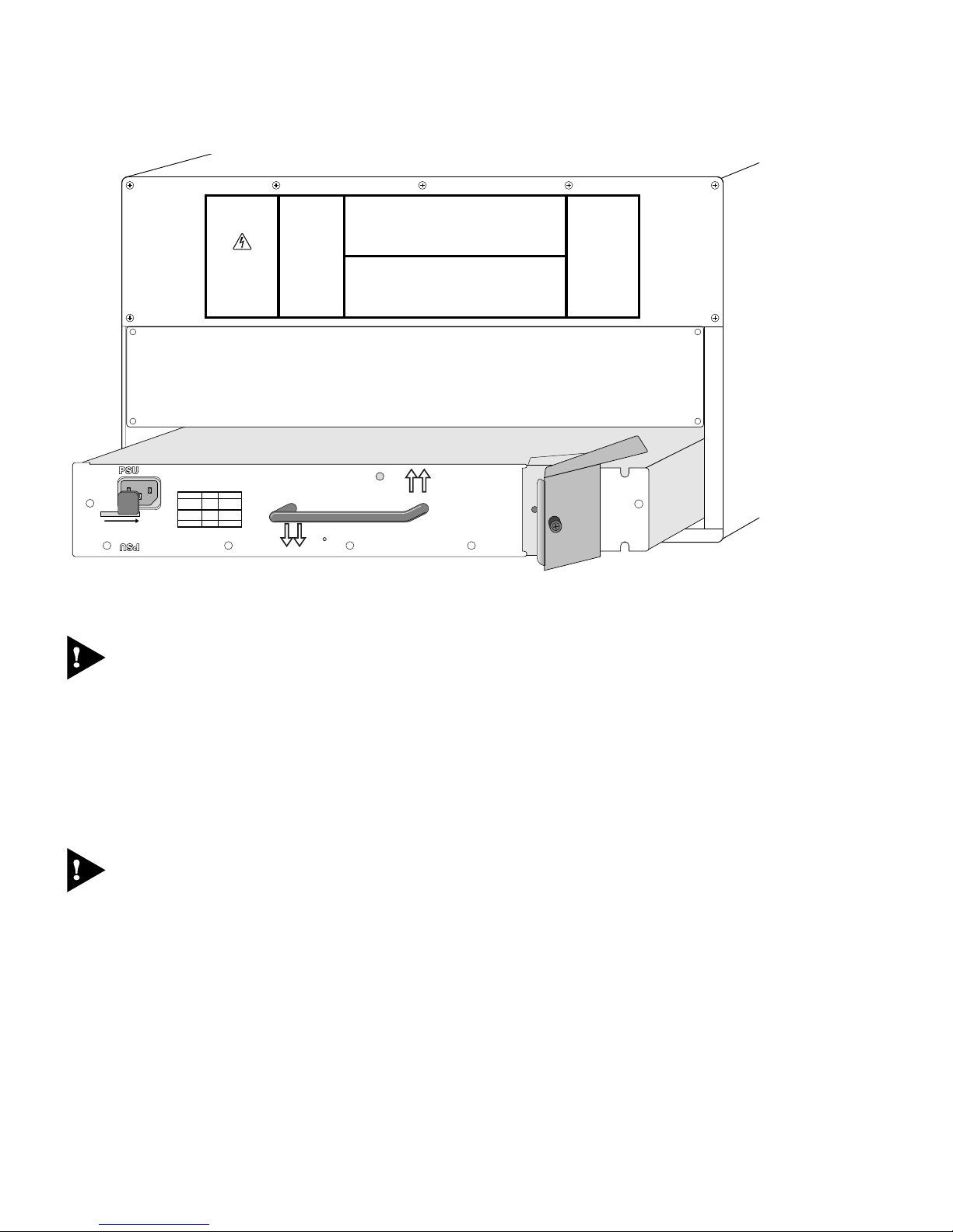
1 Locate the power supply on the lower rear of the chassis.
2 Remove the AC power cord from the power supply.
3 Slide the locking latch on the power supply so that it covers the AC power connector.
4 Unscrew the screw on the ejector/injector lever using a #2 Phillips-head screwdriver.
5 Pull the ejector/injector lever towards you while holding on to the central handle to steady the
power supply.
6 Supporting it with one hand, slide the power supply out of the chassis.
The power supply is shown in Figure 1.
3804 P
OWER SUPPLY
ART NO
P
: 122000-00 REV. 01
r
DC OK
DC OK
WHEN INSTALLED IN 3808 THIS WAY UP
38_pw
SLIDE TO REMOVE
45012
VHzA
100-120
200-2405060
60
6
13
50
13
6
VHzA
WHEN INSTALLED IN 3804 THIS WAY UP
200-240
100-120
SERVICE
Figure 1: Alpine 3804 power supply
Caution: Ensure the latch covers the AC power connector. The power supply cannot be removed
or installed unless the connector is covered.
7 Make sure that the replacement power supply is right-side up as described by the text on the front of
the power supply, that the ejector/injector lever is open, and that the safety latch covers the AC
power connector.
8 Use the centrally mounted handle to slide the power supply into the bay. Use the ejector/injector
lever to engage/disengage the power supply connectors during the last inch of insertion into the
chassis.
Caution: Do not slam the power supply into the backplane. This will cause damage and possibly
require the return of the chassis.
9 Secure the power supply by tightening the screw on the ejector/injector lever using a #2
Phillips-head screwdriver.
10 Slide the locking latch covering the AC power connector to the left until it locks into the chassis.
2
 Loading...