

Page 1

Summit WM-Series WLAN Switch and Altitude
Access Point Software Version 1.0 User Guide
Extreme Networks, Inc.
3585 Monroe Street
Santa Clara, California 95051
(888) 257-3000
http://www.extremenetworks.com
Published: September 2005
Part number: 100198-00 Rev 03
Page 2

Alpine, Altitude, BlackDiamond, EPICenter, Ethernet Everywhere, Extreme Ethernet Everywhere, Extreme
Networks, Extreme Turbodrive, Extreme Velocity, ExtremeWare, ExtremeWorks, GlobalPx Content Director, the Go
Purple Extreme Solution Partners Logo, ServiceWatch, Summit, the Summit7i Logo, and the Color Purple, among
others, are trademarks or registered trademarks of Extreme Networks, Inc. or its subsidiaries in the United States
and other countries. Other names and marks may be the property of their respective owners.
© 2005 Extreme Networks, Inc. All Rights Reserved.
Specifications are subject to change without notice.
The ExtremeWare XOS operating system is based, in part, on the Linux operating system. The machine-readable
copy of the corresponding source code is available for the cost of distribution. Please direct requests to Extreme
Networks for more information at the following address:
Software Licensing Department
3585 Monroe Street
Santa Clara CA 95051
NetWare and Novell are registered trademarks of Novell, Inc. Merit is a registered trademark of Merit Network,
Inc. Solaris and Java are trademarks of Sun Microsystems, Inc. F5, BIG/ip, and 3DNS are registered trademarks of
F5 Networks, Inc. see/IT is a trademark of F5 Networks, Inc.
sFlow® is a registered trademark of InMon Corporation.
All other registered trademarks, trademarks and service marks are property of their respective owners.
2
Summit WM-Series WLAN Switch and Altitude Access Point Software Version 1.0 User Guide
Page 3

Table of Contents
About this Guide.............................................................................................................................. 9
Who should use this guide ...........................................................................................................9
What is in this guide ...................................................................................................................9
Formatting conventions..............................................................................................................10
Documentation feedback ...........................................................................................................10
Protocols and standards.............................................................................................................11
Regulatory information ..............................................................................................................11
Chapter 1: The Summit WM-Series Switch Software solution ........................................................... 13
What is the Summit WM-Series Switch Software system?..............................................................13
Conventional wireless LANS .................................................................................................13
The Summit WM-Series Switch Software solution...................................................................14
Summit WM-Series Switch Software and your network ..................................................................17
Components of the solution: a summary ................................................................................17
Network traffic flow .............................................................................................................18
Network security .................................................................................................................19
Authentication ..............................................................................................................19
Privacy .........................................................................................................................19
Interaction with wired networks: Wireless Mobility Access Domain ...........................................20
Static routing and routing protocols ......................................................................................20
Policy: packet filtering .........................................................................................................21
Mobility and roaming...........................................................................................................21
Availability .........................................................................................................................22
Quality of Service (QoS) .......................................................................................................22
Chapter 2: Summit WM-Series Switch: Startup................................................................................ 23
Summit WM-Series Switch features and installation .....................................................................23
Installing the Summit WM-Series Switch ...............................................................................24
First-time setup of Summit WM-Series Switch .............................................................................24
Management port first-time setup .........................................................................................24
Changing the Management Port IP address: web browser method.......................................25
Adding the Summit WM-Series Switch to your enterprise network ......................................27
The graphical user interface (GUI): overview ................................................................................28
Chapter 3: Summit WM-Series Switch Software configuration.......................................................... 31
Configuration steps: overview .....................................................................................................31
Enabling the product key ...........................................................................................................31
Setting up the data ports ...........................................................................................................32
Setting up static routes..............................................................................................................35
Setting up OSPF Routing ...........................................................................................................36
Filtering at the interface level.....................................................................................................38
Port-based exception filters: built-in......................................................................................39
Port-based exception filters: user defined ..............................................................................39
Summit WM-Series WLAN Switch and Altitude Access Point Software Version 1.0 User Guide
3
Page 4

Table of Contents
Chapter 4: Altitude AP: startup ....................................................................................................... 41
Altitude AP features ..................................................................................................................41
Installing the Altitude APs .........................................................................................................43
Connecting and powering the Altitude AP ....................................................................................44
Discovery and registration: Altitude AP registration settings...........................................................44
Discovery and registration ..........................................................................................................46
Discovery steps ...................................................................................................................46
Altitude AP access approval .......................................................................................................49
Configuring properties and radios................................................................................................51
View and modify properties of registered Altitude APs.............................................................51
View and modify the radio settings of registered Altitude APs ..................................................52
Adding a Altitude AP manually .......................................................................................56
Altitude AP static configuration: branch office deployment......................................................57
Auto Cell software .....................................................................................................................58
Chapter 5: WM Access Domain Services (WM-AD): Introduction ...................................................... 61
Overview ..................................................................................................................................61
What is a WM-AD? ....................................................................................................................62
Topology of a WM-AD ................................................................................................................62
Network assignment and authentication for a WM-AD ...................................................................63
Authentication with SSID network assignment........................................................................63
Authentication with AAA (802.1x) network assignment ...........................................................64
Filtering for a WM-AD ................................................................................................................64
Privacy on a WM-AD: WEP and WPA ...........................................................................................66
Setting up a new WM-AD ...........................................................................................................66
Global Settings for a WM-AD ......................................................................................................68
Chapter 6: WM Access Domain Configuration ................................................................................. 71
Topology for a WM-AD ...............................................................................................................71
Topology for a WM-AD for Captive Portal................................................................................71
Topology for a WM-AD for AAA .............................................................................................75
Authentication for a WM-AD.......................................................................................................76
Authentication for a WM-AD for Captive Portal .......................................................................77
Authentication for a WM-AD for AAA .....................................................................................82
MAC-based authentication for a WM-AD ................................................................................82
Accounting for a WM-AD............................................................................................................84
RADIUS Policy for a WM-AD ......................................................................................................84
RADIUS Policy for Captive Portal ..........................................................................................85
RADIUS Policy for AAA and AAA groups ................................................................................85
Filtering rules for a WM-AD ........................................................................................................86
Filtering rules for an exception filter......................................................................................87
The non-authenticated filter for Captive Portal .......................................................................87
Filtering rules for a Filter ID group ........................................................................................90
Filtering rules for a default filter ...........................................................................................92
Filtering Rules for an AAA Group WM-AD.........................................................................94
Filtering rules between two wireless devices.....................................................................94
Multicast for a WM-AD ..............................................................................................................95
4
Summit WM-Series WLAN Switch and Altitude Access Point Software Version 1.0 User Guide
Page 5

Table of Contents
Privacy for a WM-AD..................................................................................................................96
Privacy for a WM-AD for Captive Portal ..................................................................................96
Privacy for a WM-AD for AAA................................................................................................97
A WM-AD with no authentication ..............................................................................................100
A WM-AD for voice traffic.........................................................................................................101
Chapter 7: Summit WM-Series Switch Configuration: Availability and Mobility ............................... 103
Availability .............................................................................................................................103
Mobility and the WM-AD Manager.............................................................................................107
VW-AD Manager and VW-AD Agent: Background...................................................................107
Chapter 8: Summit WM-Series Switch: configuring other functions ................................................ 111
Management users ..................................................................................................................111
Network time ..........................................................................................................................112
Check Point event logging ........................................................................................................113
Setting up SNMP ....................................................................................................................115
MIB support .....................................................................................................................115
Enabling SNMP on the Summit WM-Series Switch ...............................................................116
Chapter 9: Setting up third-party access points............................................................................. 119
Chapter 10: Summit Spy: detecting rogue access points................................................................ 123
Overview ................................................................................................................................123
Enabling the Analysis and RFDC Engines ..................................................................................124
Summit Spy: running scans .....................................................................................................125
The Analysis Engine ................................................................................................................126
Viewing the Scanner Status report ............................................................................................130
Chapter 11: Ongoing operation..................................................................................................... 131
Altitude AP maintenance: software ...........................................................................................131
Altitude AP client management ................................................................................................133
Client disassociate ............................................................................................................134
Client blacklist..................................................................................................................135
Summit WM-Series Switch software maintenance ......................................................................137
Summit WM-Series Switch Software logs and traces...................................................................140
Viewing log, alarm and trace messages ................................................................................141
Reports and displays ...............................................................................................................144
View displays ....................................................................................................................144
View reports......................................................................................................................146
Glossary ..................................................................................................................................... 147
Appendix A: Summit WM-Series Switch Software system states and LEDs ...................................... 167
Summit WM-Series Switch system states and LEDs....................................................................167
Altitude AP system states ........................................................................................................168
Appendix B: CLI command reference ............................................................................................ 169
Summit WM-Series WLAN Switch and Altitude Access Point Software Version 1.0 User Guide
5
Page 6

Table of Contents
Appendix C: DHCP, SLP, and Option 78 reference ......................................................................... 173
Service Location Protocol (SLP) (RFC2608)...............................................................................174
DHCP Options for Service Location Protocol (RFC2610) .............................................................174
SLP Directory Agent Option (Option 78) ....................................................................................174
SLP Service Scope Option (Option 79)......................................................................................175
Appendix D: Reference lists of standards ...................................................................................... 177
RFC list..................................................................................................................................177
802.11 standards list..............................................................................................................178
Appendix E: Support for Altitude AP.............................................................................................. 181
Altitude AP diagnostics by Telnet .............................................................................................181
Appendix F: RADIUS Attributes ..................................................................................................... 183
RADIUS Vendor-Specific Attributes (VSAs) ................................................................................183
RADIUS Accounting ................................................................................................................184
Account-Start Packet.........................................................................................................184
Account-Stop/Interim Packet..............................................................................................185
Termination Codes ............................................................................................................186
Appendix G: Logs and Events ....................................................................................................... 187
Overview ................................................................................................................................187
Critical...................................................................................................................................187
ACCESSPOINT..................................................................................................................187
CDR_COLLECTOR .............................................................................................................191
CONFIG_MANAGER ..........................................................................................................191
EVENT_SERVER ...............................................................................................................192
LANGLEY .........................................................................................................................194
RADIUS_ACCOUNTING .....................................................................................................194
RADIUS_CLIENT ..............................................................................................................194
RF_DATA_COLLECTOR......................................................................................................195
RU_MANAGER .................................................................................................................195
SECURITY_MANAGER.......................................................................................................196
STARTUP_MANAGER........................................................................................................197
STATS_SERVER................................................................................................................198
VNMGR............................................................................................................................199
Major .....................................................................................................................................200
ACCESSPOINT..................................................................................................................200
CDR_COLLECTOR .............................................................................................................201
CLI ..................................................................................................................................202
CONFIG_MANAGER ..........................................................................................................203
CPDP_AGENT_ID ..............................................................................................................203
EVENT_SERVER ...............................................................................................................204
LANGLEY .........................................................................................................................205
NSM_SERVER ..................................................................................................................205
OSPF_SERVER .................................................................................................................206
PORT_INFO_J_MANAGER..................................................................................................206
RADIUS_ACCOUNTING .....................................................................................................206
RADIUS_CLIENT ..............................................................................................................206
REDIR_ID ........................................................................................................................207
RF_DATA_COLLECTOR......................................................................................................207
6
Summit WM-Series WLAN Switch and Altitude Access Point Software Version 1.0 User Guide
Page 7

Table of Contents
RU_MANAGER .................................................................................................................208
SECURITY_MANAGER.......................................................................................................208
VNMGR............................................................................................................................210
Appendix H: Regulatory Information ............................................................................................. 213
Summit WM100 (15945), Summit WM1000 (15937) ...............................................................213
Safety ..............................................................................................................................213
Emissions.........................................................................................................................214
Environmental Operating Conditions for Summit WM100/1000 and Altitude 350-2 ................214
Altitude 350-2 Integrated Antenna AP (15938), Altitude 350-2 Detachable Antenna AP (15939) .215
United States - FCC Declaration of Conformity Statement .....................................................215
Conditions Under Which a Second party may replace a Part 15 Unlicensed Antenna ...............217
FCC RF Radiation Exposure Statement ..........................................................................217
Department of Communications Canada Compliance Statement.......................................217
European Community ........................................................................................................218
Declaration of Conformity with regard to R&TTE Directive of the European Union 1999/5/EC ...
218
Conditions of Use in the European Community...............................................................219
Permitted 5 GHz Channels for the European Community .................................................221
European Spectrum Usage Rules ..................................................................................221
Declarations of Conformity ...........................................................................................223
Certifications of Other Countries ...............................................................................................224
Index .......................................................................................................................................... 225
Summit WM-Series WLAN Switch and Altitude Access Point Software Version 1.0 User Guide
7
Page 8

Table of Contents
8
Summit WM-Series WLAN Switch and Altitude Access Point Software Version 1.0 User Guide
Page 9

About this Guide
This guide describes how to install, configure, and manage the Summit WM-Series Switch Software.
Who should use this guide
This guide is a reference for system administrators who install and manage the Summit WM-Series
Switch Software.
What is in this guide
This guide contains the following chapters:
● About this Guide describes the target audience and content of the guide, the formatting conventions
used in it, and how to provide feedback on the guide.
● Chapter 1 provides an overview of the product, its features and functionality.
● Chapter 2 describes how to perform the installation and first-time setup of the Summit WM-Series
Switch.
● Chapter 3 describes setting up the initial configuration, as well as configuring the data ports and
defining routing.
● Chapter 4 tells how to install the Altitude AP, how it discovers and registers with the Summit WM-
Series Switch, how to view and modify the radio configuration, and how to enable Dynamic Radio
Frequency Management.
● Chapter 5 provides an overview of WM Access Domain Services (WM-AD), the mechanism by
which the Summit WM-Series Switch Software controls and manages network access.
● Chapter 6 gives detailed instructions in how to configure a WM-AD, its topology, authentication,
accounting, RADIUS policy, multicast, filtering and privacy. Both Captive Portal and AAA types of
WM-AD are described.
● Chapter 7 describes how to set up the features that provide availability in the event of a Summit
WM-Series Switch failover, and mobility for a wireless device user.
● Chapter 8 includes functions, such as user privileges, network time, Check Point event logging and
SNMP.
● Chapter 9 describes how to use the Summit WM-Series Switch Software features with third-party
Altitude APs.
● Chapter 10 explains the security tool that scans for, detects and reports on rogue access points.
● Chapter 11 describes maintenance activities, such as software upgrades on both the Summit WM-
Series Switch and the Altitude AP. This chapter also includes information on the logs, traces, reports
and displays available.
● Appendix A provides a reference on the LED displays and their significance.
● Appendix B provides a list of the CLI command line syntax.
Summit WM-Series WLAN Switch and Altitude Access Point Software Version 1.0 User Guide
9
Page 10

About this Guide
● Appendix C provides background information on how the discovery process uses these network
services.
● Appendix D provides a reference list of RFCs supported.
● Appendix E provides information on a support tool.
● Appendix F provides a reference list of the RADIUS Attributes that are supported by the Summit
WM-Series Switch Software.
● Appendix G provides a reference list of the log and event messages.
● Appendix H provides regulatory information for the 6XPPLW:06HULHV6ZLWFKDQGWKH$OWLWXGH
:LUHOHVV$FFHVV3RLQW
This guide also contains a glossary of standard industry terms used in this guide.
Formatting conventions
The Summit WM-Series Switch Software documentation uses the following formatting conventions to
make it easier to find information and follow procedures:
● Bold text is used to identify components of the management interface, such as menu items and
section of pages, as well as the names of buttons and text boxes.
For example: Click Logout.
● Monospace font is used in code examples and to indicate text that you type.
For example:
● The following symbols are used to draw your attention to additional information:
Type https://<hls-address>[:mgmt-port>]
NOTE
Notes identify useful information that is not essential, such as reminders, tips, or other ways to perform a task.
WARNING!
Warnings identify essential information. Ignoring a warning can lead to problems with the application.
Documentation feedback
If you have any problems using this document, please contact your next level of support:
● Customers should contact the Extreme Networks Technical Assistance Center (TAC).
10
When you call, please have the following information ready. This will help us to identify the document
that you are referring to.
● Title: Summit WM-Series WLAN Switch and Altitude Access Point Software Version 1.0 User Guide
● Part Number: 100198-00 Rev 01
Summit WM-Series WLAN Switch and Altitude Access Point Software Version 1.0 User Guide
Page 11

Protocols and standards
Protocols and standards
Appendix D lists the protocols and standards supported by the Summit WM-Series Switch Software.
These lists include the Requests for Comment (RFCs) of the Internet Engineering Task Force (IETF) and
the 802.11 standards developed by the Institute of Electrical and Electronics Engineers (IEEE).
Regulatory information
Appendix H provides regulatory information for the Summit WM-Series Switch and the $OWLWXGH
:LUHOHVV$FFHVV3RLQW
Summit WM-Series WLAN Switch and Altitude Access Point Software Version 1.0 User Guide
11
Page 12

About this Guide
12
Summit WM-Series WLAN Switch and Altitude Access Point Software Version 1.0 User Guide
Page 13

1 The Summit WM-Series Switch Software
solution
The next generation of Extreme Networks wireless networking devices provides a truly scalable WLAN
solution. Extreme Networks Altitude APs are thin access points that are controlled through a
sophisticated network device, the Summit WM-Series Switch. This solution provides the security and
manageability required by enterprises and service providers alike.
The Summit WM-Series Switch Software system is a highly scalable wireless local area network
(WLAN) solution developed by Extreme Networks. Based on a third generation WLAN topology, the
Summit WM-Series Switch Software system makes wireless practical for medium and large-scale
enterprises and for service providers.
The Summit WM-Series Switch Software system provides a secure, highly scalable, cost-effective
solution based on the IEEE 802.11standard. The solution is intended for enterprise networks operating
on many floors in more than one building, as well as in public environments such as airports and
convention centers that require more than two access points.
This section provides an overview of the fundamental principles of the Summit WM-Series Switch
Software system: what it is, how it works, and its advantages.
What is the Summit WM-Series Switch Software
system?
The Summit WM-Series Switch Software system replaces the conventional access points used in wireless
networking with two network devices that work as a system:
● Summit WM-Series Switch: A network device that provides smart centralized control over the
elements (Altitude APs) in the wireless network.
● Altitude APs: The access points for 802.11 clients (wireless devices) in the network, controlled by the
Summit WM-Series Switch. The Altitude AP is a “fit access point” because its wireless control is
handled by the Summit WM-Series Switch. The Altitude AP is a dual-band access point, with both
802.11a and 802.11b/g radios.
Together, the Summit WM-Series Switch Software products enable a radically simplified new approach
to setting up, administering and maintaining a WLAN. Summit WM-Series Switch Software provides a
Layer 3 IP routed WLAN architecture. This architecture can be implemented over several subnets
without requiring the configuration of virtual local area networks (VLANs).
Conventional wireless LANS
At its simplest, wireless communication between two or more computers requires that each one is
equipped with a receiver/transmitter – a WLAN Network Interface Card (NIC) – capable of exchanging
digital information over a common radio frequency. This is called an ad hoc configuration. An ad hoc
network allows wireless devices to communicate together. This is an independent basic service set
(IBSS).
Summit WM-Series WLAN Switch and Altitude Access Point Software Version 1.0 User Guide
13
Page 14
The Summit WM-Series Switch Software solution
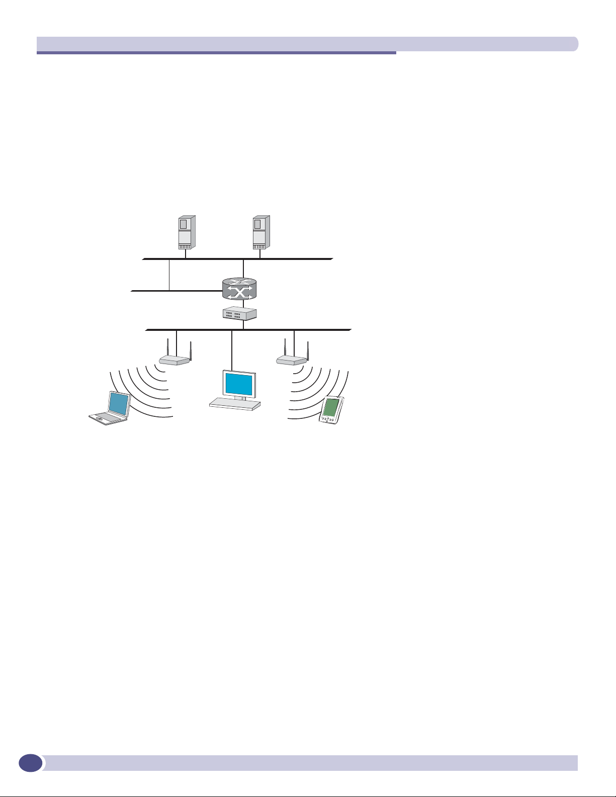
An alternative to the ad hoc configuration is the use of an access point. This may be a dedicated
hardware router or a computer running special software. Computers and other wireless devices
communicate with each other through this access point. The 802.11 standard defines Access Point
communications as devices that allow wireless devices to communicate with a “distribution system”.
This is a basic service set (BSS) or infrastructure network.
For the wireless devices to communicate with computers on a wired network, the access points must be
connected into the wired network, and provide access to the networked computers. This is called
bridging. Clearly, there are security issues and management scalability issues in this arrangement.
Figure 1: Standard wireless network solution
5$',86
DXWKHQWLFDWLRQ
VHUYHU
:LUHOHVV
GHYLFH
'+&3
VHUYHU
5RXWHU
(WKHUQHWVZLWFK
$FFHVV
SRLQW
:LUHOHVV
GHYLFH
The wireless devices and the wired networks communicate with each other using standard networking
protocols and addressing schemes. Most commonly, Internet Protocol (IP) addressing is used.
While this topology works well enough for small installations, as the network grows the difficulty of
setting up and administering all the individual access points expands as well. When the expanding
network has to cope with a large number of wireless users all signing on and off at random times, the
complexity grows rapidly. Imagine, for example, a university library filled with professors and students
– all equipped with laptops. Or a conference full of delegates and exhibitors.
14
Clearly, there must be a better way than setting up each access point individually.
The Summit WM-Series Switch Software solution
The Summit WM-Series Switch Software solution consists of two devices:
● The Summit WM-Series Switch is a rack-mountable network device designed to be integrated into an
existing wired Local Area Network (LAN). It provides centralized control over all access points (both
Altitude APs and third-party access points) and manages the network assignment of wireless device
clients associating through access points.
● The Altitude AP is a wireless LAN fit access point (IEEE 802.11) provided with unique software that
allows it to communicate only with a Summit WM-Series Switch. (A fit access point handles the radio
Summit WM-Series WLAN Switch and Altitude Access Point Software Version 1.0 User Guide
Page 15
What is the Summit WM-Series Switch Software system?
frequency (RF) communication but relies on a controller to handle WLAN elements such as
authentication.) The Altitude AP also provides local processing such as encryption.
This architecture allows a single Summit WM-Series Switch to control many Altitude APs, making the
administration and management of large networks much easier.
There can be several Summit WM-Series Switchs in the network, each with its set of registered Altitude
APs. The Summit WM-Series Switchs can also act as backups to each other, providing stable network
availability.
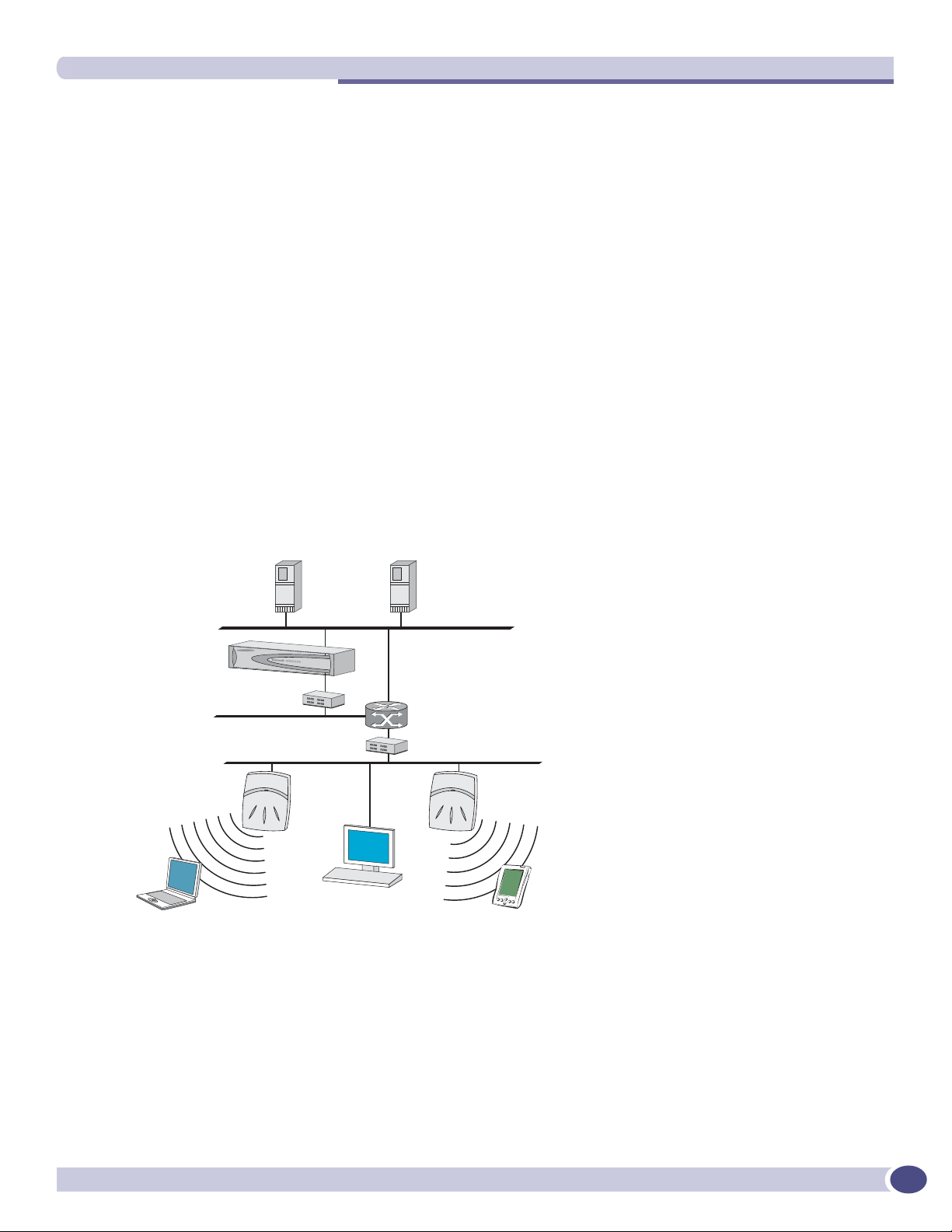
In addition to the Summit WM-Series Switchs and Altitude APs, the solution requires three other
components, which are standard for enterprise and service provider networks:
● RADIUS Server (Remote Access Dial-In User Service) (RFC2865 and RFC2866), or other
authentication server. Assigns and manages ID and Password protection throughout the network.
Used for authentication of the wireless users.
● DHCP Server (Dynamic Host Configuration Protocol) (RFC2131). Assigns IP addresses, gateways
and subnet masks dynamically. Also used by the Altitude APs to discover the location of the Summit
WM-Series Switch during the initial registration process.
● SLP (Service Location Protocol) (RFC2608) supported on the DHCP server, when SLP is used as part
of the discovery mechanism.
Figure 2: Summit WM-Series Switch Software solution
5$',86
DXWKHQWLFDWLRQ
VHUYHU
6XPPLW:0
:LUHOHVV&RQWUROOHU
(WKHUQHWVZLWFK
:LUHOHVV$3
:LUHOHVV
GHYLFH
The Summit WM-Series Switch appears to the existing network as if it were an access point, but in fact
one Summit WM-Series Switch controls many Altitude APs.
'+&3
VHUYHU
5RXWHU
(WKHUQHWVZLWFK
:LUHOHVV
GHYLFH
The Summit WM-Series Switch has built-in capabilities to recognize and manage the Altitude APs. The
Summit WM-Series Switch activates the Altitude APs, enables them to receive wireless traffic from
wireless devices, processes the data traffic from the Altitude APs and forwards or routes that data traffic
out to the network. This processing includes authenticating requests and applying access policies.
Summit WM-Series WLAN Switch and Altitude Access Point Software Version 1.0 User Guide
15
Page 16

The Summit WM-Series Switch Software solution
Simplifying the Altitude APs makes them:
● cost-effective
● easy to manage
● easy to deploy
Putting control on an intelligent centralized Summit WM-Series Switch enables:
● centralized configuration, management, reporting, maintenance
● high security
● flexibility to suit enterprise
● scalable and resilient deployments with a few Summit WM-Series Switches controlling hundreds of
Altitude APs
Here are some of the Summit WM-Series Switch Software system advantages:
Table 1: Advantages of the Summit WM-Series Switch Software system
Scales up to Enterprise capacity One Summit WM-Series Switch controls as many as 200 Altitude APs. In turn
each Altitude AP can handle up to 127 wireless devices. With additional
Summit WM-Series Switches, the number of wireless devices the system can
support is in the thousands.
Integrates in existing network A Summit WM-Series Switch can be added to an existing enterprise network as
a new network device, greatly enhancing its capability without interfering with
existing functionality. Integration of the Summit WM-Series Switches and
Altitude APs does not require any reconfiguration of the existing infrastructure
(e.g., VLANs).
Offers centralized
management and control
Provides easy deployment
of Altitude APs
Provides security via user
authentication
Provides security via filters
and privileges
Supports seamless mobility
and roaming
Integrates third-party
access points
Prevents rogue devices Unauthorized access points will be detected and identified as harmless or
Provides accounting services Summit WM-Series Switch Software logs wireless user sessions, user group
Offers troubleshooting capability Summit WM-Series Switch Software logs system and session activity and
Offers dynamic RF management Summit WM-Series Switch Software can automatically select channels and
An administrator accesses the Summit WM-Series Switch in its centralized
location to monitor and administer the entire wireless network. The Summit
WM-Series Switch has functionality to recognize, configure, and manage the
Altitude APs and distribute new software releases.
The initial configuration of the Altitude APs on the centralized Summit WMSeries Switch can be done with an automatic “discovery” technique.
Summit WM-Series Switch Software uses existing authentication (AAA) servers
to authenticate and authorize users.
Summit WM-Series Switch Software uses virtual networking techniques to
create separate virtual networks with defined authentication and billing
services, access policies and privileges.
Summit WM-Series Switch Software supports seamless roaming of a wireless
device from one Altitude AP to another on the same Summit WM-Series Switch
or on a different Summit WM-Series Switch.
Summit WM-Series Switch Software can integrate legacy third-party access
points, using a combination of network routing and authentication techniques.
dangerous rogue APs.
activity, and other activity reporting, enabling the generation of consolidated
billing records.
provides reports to aid in troubleshooting analysis.
adjust Radio Frequency (RF) signal propagation power levels without user
intervention.
16
Summit WM-Series WLAN Switch and Altitude Access Point Software Version 1.0 User Guide
Page 17

Summit WM-Series Switch Software and your network
Summit WM-Series Switch Software and your network
Components of the solution: a summary
The following is a summary checklist of the components of the Summit WM-Series Switch Software
solution on your enterprise network. These are described in detail in this guide.
● The Summit WM-Series Switch, providing centralized control over all access points (both Altitude
APs and third-party access points) and manages the network assignment of wireless device clients
associating through access points.
● The Altitude AP is a wireless LAN thin access point (IEEE 802.11) that communicates only with a
Summit WM-Series Switch.
● RADIUS Server (Remote Access Dial-In User Service) (RFC2865), or other authentication server.
Assigns and manages ID and Password protection throughout the network. Used for authentication
of the wireless users in either 802.1x or Captive Port security modes.
The RADIUS Server system can be set up for certain standard attributes, such as Filter-ID, and for
the Vendor Specific Attributes (VSAs).
● DHCP Server (Dynamic Host Configuration Protocol) (RFC2131). Assigns IP addresses, gateways
and subnet masks dynamically. IP address assignment for clients can be done by the DCHP server
internal to the Summit WM-Series Switch, or by existing servers using DHCP relay. Also used by the
Altitude APs to discover the location of the Summit WM-Series Switch during the initial registration
process. For SLP, DHCP should have Option 78 enabled (Option 78 specifies the location of one or
more SLP Directory Agents).
● Service Location Protocol (SLP) (SLP RFC2608). Client applications are User Agents and services are
advertised by Service Agents. In larger installations, a Directory Agent collects information from
Service Agents and creates a central repository. The Extreme Networks solution relies on registering
“extreme” as an SLP Service Agent.
● Domain Name Server (DNS), for an alternate mechanism (if present on the enterprise network) for
the automatic discovery process. Summit WM-Series Switch Software relies on the DNS for Layer 3
deployments and for static configuration of Altitude APs. The Extreme Networks solution relies on
registering “controller” as the DNS name.
● Web Authentication Server, if desired for external authentication.
● RADIUS Accounting Server (Remote Access Dial-In User Service) (RFC2866), if RADIUS
Accounting is enabled.
● Simple Network Management Protocol (SNMP) Manager Server, if forwarding SNMP messages is
enabled.
● Check Point Server, Check Point Event Logging API (ELA), for security event logging if a firewall
application is enabled.
● Network infrastructure, Ethernet switches and routers, must be configured to allow routing between
the various services noted above.
Routing must also be enabled between multiple Summit WM-Series Switches, for such Summit WMSeries Switch Software features as Availability, WM-AD Manager for mobility, Third-Party Access
Points, and Summit Spy for detection of rogue access points (some features require the definition of
static routes).
● Web Browser, providing access to the Summit WM-Series Switch Management GUI to configure
Summit WM-Series Switch Software.
Summit WM-Series WLAN Switch and Altitude Access Point Software Version 1.0 User Guide
17
Page 18
The Summit WM-Series Switch Software solution
● a device that supports SSH, for serial port access to the Command Line Interface (CLI), for file
management and monitoring by a network technician.
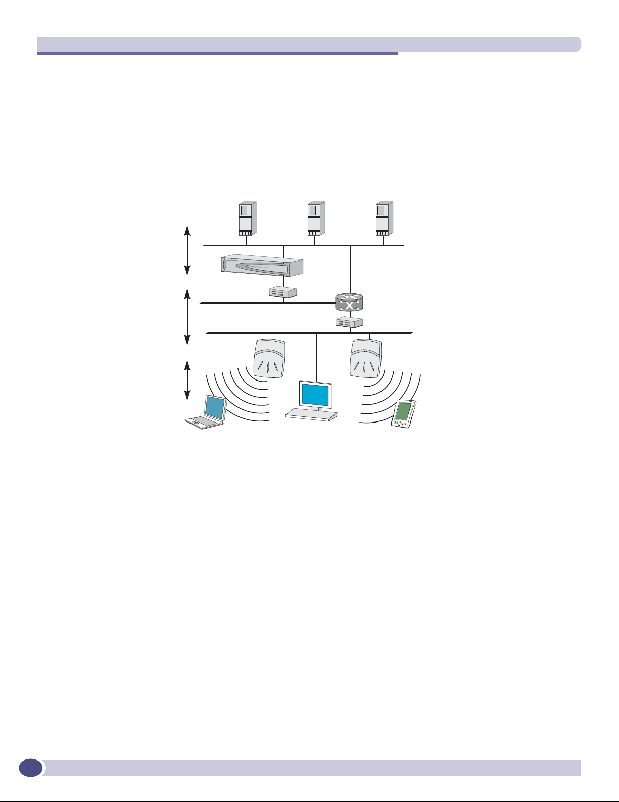
Network traffic flow
Figure 3: Traffic Flow diagram
6XPPLW:0:LUHOHVV&RQWUROOHU
FRQWUROURXWLQJ
6:&DXWKHQWLFDWHV
ZLUHOHVVXVHUIRUZDUGV,3
SDFNHWWRZLUHGQHWZRUN
6XPPLW:0:LUHOHVV&RQWUROOHU
:LUHOHVV$3WXQQHOLQJ
$3VHQGVGDWDWUDIILFWR6:&
Â
WKURXJKD8'3WXQQHO
6:&FRQWUROV$3WKURXJK
Â
D8'3WXQQHO
8VLQJWKH8'3WXQQHOV6:&
Â
DOORZVZLUHOHVVFOLHQWVWR
URDPWR$3VRQGLIIHUHQW6:&V
,3SDFNHWWUDQVPLVVLRQ
EHDFRQSUREH
ZLUHOHVVGHYLFHDVVRFLDWHV
ZLWKD:LUHOHVV$3E\LWV66,'
6XPPLW:0
:LUHOHVV&RQWUROOHU
:LUHOHVV$3
:LUHOHVVGHYLFH
5$',86
DXWKHQWLFDWLRQ
VHUYHU
'+&3
VHUYHU
(WKHUQHW
VZLWFK
([WHUQDOZHE
DXWKHQWLFDWLRQ
VHUYHU
5RXWHU
(WKHUQHWVZLWFK
:LUHOHVVGHYLFH
The diagram above shows a simple configuration with a single Summit WM-Series Switch and two
Altitude APs, each supporting a wireless device. A RADIUS server on the network provides
authentication, and a DHCP server is used by the Altitude APs to discover the location of the Summit
WM-Series Switch during the initial registration process. Also present in the network are routers and
ethernet switches.
18
Each wireless device sends IP packets in the 802.11 standard to the Altitude AP. The Altitude AP uses a
UDP (User Datagram Protocol) based tunnelling protocol to encapsulate the packets and forward them
to the Summit WM-Series Switch.
The Summit WM-Series Switch decapsulates the packets, and routes these to destinations on the
network, after authentication by the RADIUS server.
The Summit WM-Series Switch functions like a standard router, except that it is configured to route
only network traffic associated with wireless connected users. The Summit WM-Series Switch can also
be configured to simply forward traffic to a default or static route if dynamic routing is not preferred.
Summit WM-Series WLAN Switch and Altitude Access Point Software Version 1.0 User Guide
Page 19

Summit WM-Series Switch Software and your network
Network security
The Summit WM-Series Switch Software system provides features and functionality to control network
access. These are based on standard wireless network security practices.
Current wireless network security methods provide a degree of protection. These methods include:
● Shared Key authentication that relies on Wired Equivalent Privacy (WEP) keys
● Open System that relies on Service Set Identifiers (SSIDs)
● 802.1x that is compliant with Wi-Fi Protected Access (WPA)
● Captive Portal based on Secure Sockets Layer (SSL) protocol
The Summit WM-Series Switch Software system supports these encryption approaches:
● Wired Equivalent Privacy (WEP), a security protocol for wireless local area networks defined in the
802.11b standard
● Wi-Fi Protected Access version 1 (WPA1
● Wi-Fi Protected Access version 2 (WPA2
Mode with Chipher Block Chaining Message Authentication Code (CCMP).
TM
) with Temporal Key Integrity Protocol (TKIP)
TM
) with Advanced Encryption Standard (AES) and Counter
Authentication
The Summit WM-Series Switch relies on a RADIUS server, or authentication server, on the enterprise
network to provide the authentication information (whether the user is to be allowed or denied access
to the network).
The Summit WM-Series Switch provides authentication using:
● Captive Portal, a browser-based mechanism that forces users to a web page
● RADIUS (using IEEE 802.1x)
The 802.1x mechanism is a standard for authentication developed within the 802.11 standard. This
mechanism is implemented at the port, blocking all data traffic between the wireless device and the
network until authentication is complete. Authentication by 802.1x standard uses Extensible
Authentication Protocol (EAP) for the message exchange between the Summit WM-Series Switch and
the RADIUS server.
When 802.1x is used for authentication, the Summit WM-Series Switch provides the capability to
dynamically assign per-wireless-device WEP keys (called per-station WEP keys in 802.11).
In Summit WM-Series Switch Software, a RADIUS redundancy feature is provided, where you can
define a failover RADIUS server (up to 2 servers) in the event that the active RADIUS server fails.
Privacy
Privacy is a mechanism that protects data over wireless and wired networks, usually by encryption
techniques.
Summit WM-Series Switch Software supports the Wired Equivalent Privacy (WEP) standard common to
conventional access points.
Summit WM-Series WLAN Switch and Altitude Access Point Software Version 1.0 User Guide
19
Page 20

The Summit WM-Series Switch Software solution
It also provides Wi-Fi Protected Access version 1 (WPA v.1) encryption, based on Pairwise Master Key
(PMK) and Temporal Key Integrity Protocol (TKIP). The most secure encryption mechanism is WPA
version 2 using Advanced Encryption Standard (AES).
Interaction with wired networks: Wireless Mobility Access
Domain
Summit WM-Series Switch Software provides a versatile means of mapping wireless networks to the
topology of an existing wired network. This is accomplished through the assignment of WM Access
Domain Services.
When you set up WM Access Domain Services (WM-AD) on the Summit WM-Series Switch, you are
defining subnets for groups of wireless users. This WM-AD definition creates a virtual IP subnet where
the Summit WM-Series Switch acts as a default gateway for wireless devices.
This technique enables policies and authentication to be applied to the groups of wireless users on a
WM-AD, as well as the collecting of accounting information on user sessions that can be used for
billing.
When a WM-AD is set up on the Summit WM-Series Switch:
● one or more Altitude APs (by radio) are associated with it
● a range of IP addresses is set aside for the Summit WM-Series Switch’s DHCP server to assign to
wireless devices
If routing protocol is enabled, the Summit WM-Series Switch advertises the WM-AD as a routable
network segment to the wired network, and routes traffic between the wireless devices and the wired
network.
Each radio on a Altitude AP can participate in up to four WM-ADs, via the multi-SSID function.
Static routing and routing protocols
Routing can be used on the Summit WM-Series Switch to support the WM-AD definitions.
In the User Interface, you can configure routing on the Summit WM-Series Switch to use one of the
following routing techniques:
● Static routes: Use static routes to set the default route of a Summit WM-Series Switch so that
legitimate wireless device traffic can be forwarded to the default gateway.
● Open Shortest Path First (OSPF, version 2) (RFC2328): Use OSPF to specify the next best hop (route)
of a Summit WM-Series Switch. Open Shortest Path First (OSPF) is a protocol designed for medium
and large IP networks, with the ability to segment routers into different routing areas for routing
information summarization and propagation.
● Next Hop Routing: Use next hop routing as part of a WM-AD definition to specify a unique default
gateway to which traffic on a unique WM-AD is forwarded.
20
Summit WM-Series WLAN Switch and Altitude Access Point Software Version 1.0 User Guide
Page 21

Summit WM-Series Switch Software and your network
Policy: packet filtering
Policy refers to the rules that allow different network access to different groups of users. The Summit
WM-Series Switch Software system can link authorized users to user groups. These user groups then
can be confined to predefined portions of the network.
In the Summit WM-Series Switch Software system, policy is carried out by means of packet filtering,
within a WM-AD.
In the Summit WM-Series Switch user interface, you set up a filtering policy by defining a set of
hierarchical rules that allow (or deny) traffic to specific IP addresses, IP address ranges, or services
(ports). The sequence and hierarchy of these filtering rules must be carefully designed, based on your
enterprise’s user access plan.
The authentication technique selected determines how filtering is carried out:
● If authentication is by SSID and Captive Portal, a non-authenticated filter will allow all users to get
as far as the Captive Portal web page, where login occurs. When authentication is returned, then
filters are applied, based on user ID and permissions.
● If authentication is by AAA (802.1x), users will already have logged in and have been authenticated
before being assigned an IP address. At this point, filters are applied, based on user ID and
permissions.
Mobility and roaming
The 802.11 standard allows a wireless device to preserve its IP connection when it roams from one
access point to another on the same subnet. However, if a user roams to an access point on a different
subnet, the user is disconnected.
Summit WM-Series Switch Software has functionality that supports mobility on any subnet in the
network. Wireless device users can roam between Altitude APs on any subnet without having to renew
the IP connection.
The Summit WM-Series Switch stores the wireless device’s current session information, such as IP
address and MAC address. If the wireless device has not disassociated, then when it requests network
access on a different Altitude AP, the Summit WM-Series Switch can match its session information and
recognize it as still in a current session.
In addition, a Summit WM-Series Switch can learn about other Summit WM-Series Switches on the
network, and then exchange client session information. This enables a wireless device user to roam
seamlessly between different Altitude APs on different Summit WM-Series Switches.
Summit WM-Series WLAN Switch and Altitude Access Point Software Version 1.0 User Guide
21
Page 22

The Summit WM-Series Switch Software solution
Availability
Summit WM-Series Switch Software provides seamless availability against Altitude AP outages, Summit
WM-Series Switch outages, and even network outages.
For example, if one Altitude AP fails, coverage for the wireless device is automatically provided by the
next nearest Altitude AP.
If a Summit WM-Series Switch fails, all of its associated Altitude APs, or access points, can
automatically migrate to another Summit WM-Series Switch that has been defined as the secondary or
backup Summit WM-Series Switch. When the original Summit WM-Series Switch returns to the
network, the Altitude APs automatically re-establish their normal connection with their original Summit
WM-Series Switch.
Quality of Service (QoS)
Summit WM-Series Switch Software provides advanced Quality of Service (QoS) management, in order
to provide better network traffic flow. Such techniques include:
● WMM (Wi-Fi Multimedia): enabled globally on the Altitude AP. For devices with WMM enabled.,
the standard provides multimedia enhancements for audio, video, and voice applications. WMM
shortens the time between transmitting packets for higher priority traffic. WMM is part of the
802.11e standard for QoS.
● IP ToS (Type of Service) or DSCP (Diffserv Codepoint): the ToS/DSCP field in the IP header of a
frame is used to indicate the priority and Quality of Service for each frame. The IP TOS and/or
DSCP is maintained within CTP (CAPWAP Tunneling Protocol) by copying the user IP QoS
information to the CTP header — this is referred to as Adaptive QoS.
Quality of Service (QoS) management is also provided by:
● assigning high priority to an SSID (configurable)
● Adaptive QoS (automatic)
● support for legacy devices that use SpectraLink Voice Protocol (SVP) for prioritizing voice traffic
(configurable)
22
Summit WM-Series WLAN Switch and Altitude Access Point Software Version 1.0 User Guide
Page 23

2 Summit WM-Series Switch: Startup
Summit WM-Series Switch features and installation
The Summit WM-Series Switch is a network device designed to be integrated into an existing wired
Local Area Network (LAN).
Figure 4: The Summit WM-Series Switch
The Summit WM-Series Switch provides centralized management, network access and routing to
wireless devices that are using Altitude APs to access the network. It can also be configured to handle
data traffic from third-party access points.
The Summit WM-Series Switch performs the following functions:
● Controls and configures Altitude APs, providing centralized management
● Authenticates wireless devices that contact a Altitude AP
● Assigns each wireless device to a WM-AD when it connects
● Routes traffic from wireless devices, using WM-ADs, to the wired network
● Applies filtering policies to the wireless device session
● Provides session logging and accounting capability
The Summit WM-Series Switch is rack-mountable. It comes in the following product families:
Model Number Specifications
Summit WM-Series
Switch Summit
WM100
Summit WM-Series
Switch Summit
WM1000
• Four Fast-Ethernet ports, (10/100 BaseT), supporting up to 75 Altitude APs
• One management port, (10/100 BaseT)
• One console port (DB9 serial)
• Power supply redundant (R)
• Two GigE ports (dual 1GB SX network interfaces), supporting up to 200 Altitude APs
• One management port, (10/100 BaseT)
• One console port (DB9 serial)
• Power supply redundant (R)
Summit WM-Series WLAN Switch and Altitude Access Point Software Version 1.0 User Guide
23
Page 24
Summit WM-Series Switch: Startup
Installing the Summit WM-Series Switch
Before you begin installation, make sure that a site survey has been done, to determine the number and
location of Altitude APs and Summit WM-Series Switches required. The site survey should take a
number of factors into consideration, including:
● coverage areas
● number of users
● architectural features that affect transmission
● existing wired network and access to ethernet cabling
● type of mount (wall, ceiling, plenum) for Altitude APs
● type of power (Power-over-Ethernet or AC adaptor) for Altitude APs
● physical security of the Summit WM-Series Switch, including access control
Installing the Summit WM-Series Switch
1 Unpack and mount the Summit WM-Series Switch following the detailed instructions in the Quick
Start Guide
2 Install the ferrite beads provided, black for the power cord and white for the ethernet cables, as
described in the Quick Start Guide.
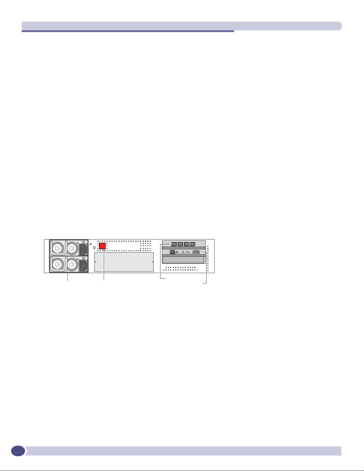
3 Plug the Summit WM-Series Switch power supply (single or dual) in to the back of the Controller.
Figure 5: The Summit WM-Series Switch – back view diagram
3RZHUVXSSO\ 3RZHU2Q2IIVZLWFK
4 Perform initial setup of the Summit WM-Series Switch to change its factory default IP address.
5 After that, connect the Summit WM-Series Switch to the enterprise LAN.
'DWDSRUWVRU
0DQDJHPHQWSRUWV
First-time setup of Summit WM-Series Switch
Management port first-time setup
Before you can connect the Summit WM-Series Switch to the enterprise network, you must change the
IP address of the Summit WM-Series Switch management port from its factory default to the IP address
suitable for your enterprise network.
24
Access the Summit WM-Series Switch for initial setup by one of two methods:
● a device supporting VT100 emulation such as a PC running HyperTerm, attached to the Summit
WM-Series Switch’s DB9 serial port (COM1 port) via a cross-over (null modem) cable. The
Summit WM-Series WLAN Switch and Altitude Access Point Software Version 1.0 User Guide
Page 25
First-time setup of Summit WM-Series Switch
Command Line Interface (CLI) commands for the initial setup are described in an attached
appendix.
● a laptop computer, running a web browser such as Internet Explorer 6.0 (or higher), attached to the
Summit WM-Series Switch’s ethernet Management Port (RJ45 port) via an ethernet cross-over cable
(cable provided with the Summit WM-Series Switch). The steps for initial setup in the Graphical
User Interface are described below.
The factory default management port setup of the Summit WM-Series Switch is:
Hostname: SWM
Management Port IP address: 192.168.10.1:5825
Management Network Mask: 255.255.255.0
Changing the Management Port IP address: web browser method
1 Connect a cross-over ethernet cable between the ethernet port of the laptop and ethernet
Management Port of the Summit WM-Series Switch.
2 Statically assign an unused IP address in the 192.168.10.0/24 subnet for the ethernet port of the PC
(for example, 192.168.10.205).
3 Run Internet Explorer (version 6.0 or above) or other web browser on the laptop.
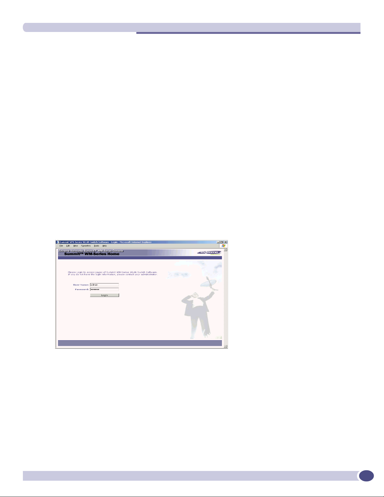
4 Point the browser to the URL https://192.168.10.1:5825. This URL launches the web-based GUI on
the Summit WM-Series Switch. The login screen appears.
Summit WM-Series WLAN Switch and Altitude Access Point Software Version 1.0 User Guide
25
Page 26
Summit WM-Series Switch: Startup
5 Key in the factory default User Name (“admin”) and Password (“abc123”). Click on the Login
button. The main menu screen appears.
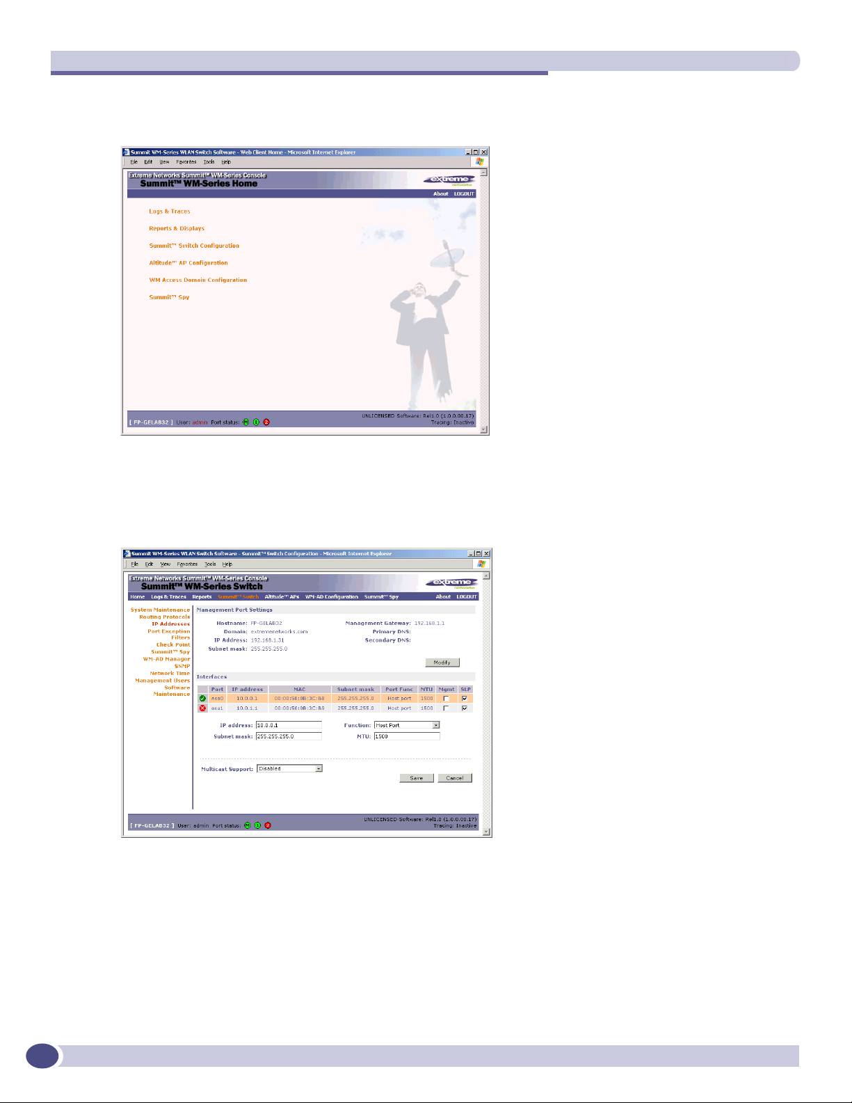
6 Click on the Summit WM-Series Switch Configuration menu option to navigate to the Summit WM-
Series Switch Configuration screen.
7 In the left-hand list, click on the IP Addresses option. The Management Port Settings area (top
portion of the screen) displays the factory settings for the Summit WM-Series Switch.
26
Summit WM-Series WLAN Switch and Altitude Access Point Software Version 1.0 User Guide
Page 27
First-time setup of Summit WM-Series Switch
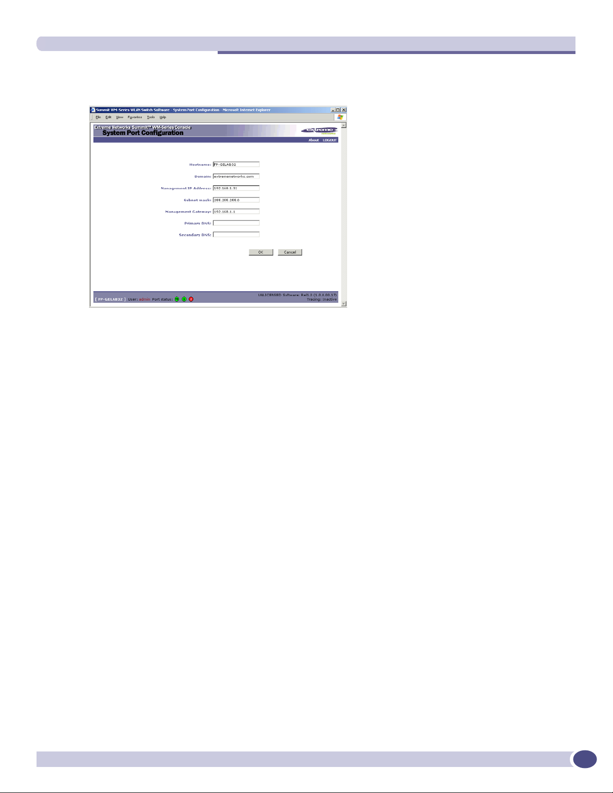
8 To modify Management Port Settings, click the Modify button. The System Port Configuration screen
appears.
9 Key in:
Hostname The name of the Summit WM-Series Switch
Domain The IP domain name of the enterprise network
Management IP Address The new IP address for the Summit WM-Series Switch’s
management port (change this as appropriate to the enterprise
network).
Subnet mask For the IP address, the appropriate subnet mask to separate the
network portion from the host portion of the address (typically
255.255.255.0)
Management Gateway The default gateway of the network.
Primary DNS The primary name server used by the network.
Secondary DNS The secondary name server used by the network
10 Click OK to return to the Summit WM-Series Switch Configuration screen.
11 Click on the Save button to save the port changes.
The web connection between the laptop and the Summit WM-Series Switch is now lost, because their IP
addresses are now on different networks.
Adding the Summit WM-Series Switch to your enterprise network
1 Disconnect the laptop from the Summit WM-Series Switch Management Port.
2 Connect the Summit WM-Series Switch Management Port to the enterprise ethernet LAN.
The Summit WM-Series Switch resets automatically. Now you will be able to launch the Summit WMSeries Switch Software GUI again, with the system visible to the enterprise network.
The remaining steps in initial configuration of the Summit WM-Series Switch Software system are
described in the next topic, after an overview of the GUI.
Summit WM-Series WLAN Switch and Altitude Access Point Software Version 1.0 User Guide
27
Page 28

Summit WM-Series Switch: Startup
The graphical user interface (GUI): overview
The administrator can configure and administer the Summit WM-Series Switch Software system using
the web-based Graphical User Interface.
To run the graphical user interface
1 Launch Microsoft Internet Explorer (version 6.0 or above), or other web browser.
2 In the address bar, key in the URL https://x.x.x.x:5825 (your management gateway as defined in
initial setup plus port 5825, formerly factory default 192.168.10.1:5825). The Summit WM-Series
Switch Software login screen appears.
3 Key in the factory default User Name (”admin”) and Password (“abc123”). Click on the Login
button. The main menu screen appears.
NOTE
You can define which user names have full read/write access to the user interface (“Admin” users) and which
users have “read-only” privileges. This is done the Summit WM-Series Switch Configuration: Management Users
screen.
The main areas in the Summit WM-Series Switch Software user interface are accessed from the main
menu, or by clicking on the appropriate tab across the top of each screen. Within each area, to access the
associated subscreens, click on the screen name in the left-hand list.
Table 2: Summit WM-Series Switch Software user interface summary
Tab Screen Function
Logs & Traces Logs normal events and alarm events
Trace logs are by component.
Reports & Displays Access to various on-screen reports
Summit WM-Series Switch
Configuration
Altitude AP Configuration Highlight a AP
System Maintenance
Routing Protocols
IP Addresses
Check Point
Summit Spy
WM-AD Manager
SNMP
Network Time
Management Users
Software Maintenance
Access Approval
AP Maintenance
AP Registration
Client Disassociate
Tasks including shutdown, enable syslog.
Define static routes, configure OSPF.
Set up management port (Modify screen)
Set up the data ports.
Enable event logging for Check Point.
Enable “detect rogue APs” mechanism.
Manage multiple Summit WM-Series Switches.
Enable SNMP messages to be sent.
Configure synchronized time.
Define user level.<
Product Keys and software upgrades.
Modify properties, radios, static config.
Modify the status of a Altitude AP.
View and set up AP software upgrade.
Define registration mode, pairing of APs.
Force a wireless device to disassociate.
28
Summit WM-Series WLAN Switch and Altitude Access Point Software Version 1.0 User Guide
Page 29

The graphical user interface (GUI): overview
Table 2: Summit WM-Series Switch Software user interface summary (Continued)
Tab Screen Function
WM-AD Configuration Global Settings
Add a subnet
WM-AD Topology
WM-AD Authen & Acct
WM-AD RADIUS Policy
WM-AD Filtering
WM-AD Privacy
Summit Spy Configure and view reports for the Summit Spy
Define RADIUS servers,& global settings
Left-hand list. Enter name. Click to add.
Define the WM-AD topology, authentication and
accounting set up
Define Filter IDs
Define filtering rules to control access
Set up WEP keys or WPA privacy.
(rogue access point detection)
Summit WM-Series WLAN Switch and Altitude Access Point Software Version 1.0 User Guide
29
Page 30

Summit WM-Series Switch: Startup
30
Summit WM-Series WLAN Switch and Altitude Access Point Software Version 1.0 User Guide
Page 31

3 Summit WM-Series Switch Software
configuration
Configuration steps: overview
To set up and configure the Summit WM-Series Switch and Altitude APs, follow these steps:
1 First-time Setup: Perform “First-Time Setup” of the Summit WM-Series Switch on the physical
network to modify the Management Port IP address for the enterprise network.
2 Product Key: Apply a Product Key file, for licensing purposes.
3 Data Port Setup: Set up the Summit WM-Series Switch on the network by configuring the physical
data ports and their function as “host port”, “router port”, or “3rd party AP port”.
4 Routing Setup: For any port defined as a “router port”, configure static routes and OSPF parameters,
if appropriate to the network
5 Altitude AP Initial Setup: Connect the Altitude APs to the Summit WM-Series Switch. They will
automatically begin the “Discovery” of the Summit WM-Series Switch, based on factors that include:
● their Registration mode (in the Altitude AP Registration screen)
● the enterprise network services that will support the discovery process.
6 Altitude AP Configuration: Modify properties or settings of the Altitude AP, if desired.
7 WM Access Domain Services Setup: Set up one or more virtual subnetworks on the Summit WM-Series
Switch. For each WM-AD, configure the following:
● Topology: configure the WM-AD, and assign the Altitude APs radios to the WM-AD.
● Authentication and Accounting: configure the authentication method for the wireless device user
and enable the accounting method.
● RADIUS Policy: define Filter ID values for user groups
● Filtering: define filtering rules to control network access
● Multicast: define groups of IP addresses for multicast traffic
● Privacy: select and configure the wireless security method on the WM-AD.
Enabling the product key
Once the “First-Time Setup” is complete, the next step in the initial setup of the Summit WM-Series
Switch is to enter your product key. This is a one-time event. The Product Key file is provided with
your Summit WM-Series Switch in a downloaded file.
For assistance, if you cannot find the product key, contact your local representative. To find your nearest
service organization, access the Extreme Networks website at www.extremenetworks.com, and then
select your country’s Extreme website from the drop-down list. The service organizations for your
country will be listed on the local site. This product area is IP Convergence Solutions or Wireless.
If no Product Key is enabled, the Summit WM-Series Switch functions with all features enabled in
demonstration mode.
Summit WM-Series WLAN Switch and Altitude Access Point Software Version 1.0 User Guide
31
Page 32

Summit WM-Series Switch Software configuration
Enabling the product key on the Summit WM-Series Switch
1 Click on the Summit Switch tab. The Summit WM-Series Switch Configuration screen appears. Click
on the Software Maintenance option. Then click on the SWM Product Keys tab. The Product Keys
screen appears.
The top portion of the screen displays the current Product Key settings. The lower portion permits
you to browse for a Product Key file and apply it.
2 To select a product key file, click Browse to navigate to a downloads folder or a CD drive.
3 To activate this product key file, click Apply Now.
Setting up the data ports
The next step in the initial setup of the Summit WM-Series Switch is to configure the physical data
ports.
Configuring the data port interfaces on the Summit WM-Series Switch
1 Click on the Summit Switch tab. In the Summit WM-Series Switch Configuration screen, click on the IP
Address option. The Management Port Settings and Interfaces screen appears.
The lower portion of the Summit WM-Series Switch Configuration screen displays the Interfaces, either
the four ethernet ports (for the Summit WM100 and Summit WM1000), or the two ports (for the
Summit WM1000). For each port, the MAC address is displayed automatically.
32
Summit WM-Series WLAN Switch and Altitude Access Point Software Version 1.0 User Guide
Page 33

2 Click in a port row to highlight it.
3 For the highlighted port, key in the:
Setting up the data ports
IP address IP Address of the physical ethernet port.
Subnet mask For the IP address, the appropriate subnet mask to separate the network
portion from the host portion of the address (typically 255.255.255.0)
MTU Maximum Transmission Unit (maximum packet size for this port). Default
setting is 1500. If you change this setting, and are using OSPF, be sure that
the MTU of each port in the OSPF link matches.
NOTE
In a “Branch Office” scenario, where the Altitude AP is configured statically on a local network whose MTU is
lower than 1500, the Summit WM-Series Switch automatically adjusts the MTU size to prevent packet
fragmentation.
4 For the highlighted port, select its Function from the drop-down list: Host Port, 3rd Party AP, Router
(defined below).
For OSPF routing on a port, that port must be configured as a “Router” Port. No more than one port
should be configured as a router port.
5 To allow Management traffic on a highlighted port, click the Mgmt checkbox on. This choice must be
used carefully since it overrides the built-in protection filters on the port.
6 For the highlighted port, click the SLP checkbox on to allow SLP protocol on this port for Altitude
APs using this port for discovery and registration.
7 To save the port configuration, click Save.
To cancel the entries without saving, click Cancel.
Summit WM-Series WLAN Switch and Altitude Access Point Software Version 1.0 User Guide
33
Page 34

Summit WM-Series Switch Software configuration
Port Type or Function
A new Summit WM-Series Switch is shipped from the factory with all its data ports set up as “Host
ports”, and support of management traffic disabled on all data ports. In the Summit WM-Series Switch
Configuration – IP Addresses screen, you can redefine the data ports to function as one of three types:
● Host Port
Use “Host Port” for connecting Altitude APs, with no dynamic routing. A “Host Port” has dynamic
routing disabled to ensure that the port does not participate in dynamic routing operations, such as
OSPF, to advertise the availability of WM-ADs hosted by the Summit WM-Series Switch. “Host
Ports” may still be used as the target for static route definitions.
● Third-Party AP Port
Define as “3rd-Party AP” a port to which you will connect third-party access points. No more than
one port can be configured for third-party APs.
Selecting this option prepares the port to support a third-party AP setup that allows the mapping of
an WM-AD to the physical port. The WM-AD settings then permit the definition of policy, such as
filters and Captive Portal, that manage the traffic flow for wireless users connected to these access
points.
The third-party access points must be operating as layer-2 bridges. The “third-party AP” WM-AD is
isolated from the rest of the network. The Summit WM-Series Switch assumes control over the layer3 functions such as DHCP.
Altitude APs must not be attached to a “3rd-Party AP” port.
● Router Port
Define as “Router Port” a port that you wish to connect to an upstream next-hop router in the
network. Dynamic routing protocol such as OSPF can be turned on for this port type.
Altitude APs can be attached to a “Router” port. The Summit WM-Series Switch will create a virtual
WM-AD port and handle wireless device traffic in the same manner as a “Host port”. Third-party
access points must not be directly connected to a “Router” port.
There is a fourth port type that is not configurable in the user interface:
● WM Access Domain Services (WM-AD) interface
An WM-AD port is a virtual port created automatically on the Summit WM-Series Switch when a
new WM-AD is defined. The WM-AD port becomes the default gateway for wireless devices on this
WM-AD. No Altitude APs can be associated with an WM-AD port and no routing is permitted on
this port.
The chart below summarizes the port types and their functions:
Table 3: Port types and functions
Altitude AP
Port Type IP Forwarding
Host No Yes Selectable No
3rd-Party AP No No Selectable No
Router Selectable.
Route wireless
device traffic only
support
Yes Selectable Selectable
Mgmt traffic support (SNMP,
HTTP, TELNET, SLP, RADIUS,
DHCP)
WM-AD No No Selectable No
Routing protocol
support (IP, OSPF
and PIM)
34
Summit WM-Series WLAN Switch and Altitude Access Point Software Version 1.0 User Guide
Page 35

Setting up static routes
Setting up static routes
It is recommended that you define a default route to your enterprise network, either with a static route
or by using OSPF protocol. This will enable the Summit WM-Series Switch to forward wireless packets
to the remainder of the network.
Setting up a static route on the Summit WM-Series Switch
1 Click on the Summit Switch tab. In the Summit WM-Series Switch Configuration screen, click on the
Routing Protocols option.
2 Click the Static Routes tab. The Static Routes screen appears.
3 To add a new route, click in the Destination Address field and key in the destination IP address of a
packet.
[The destination network IP address that this static route applies to. Packets with this destination
address will be sent to the Destination below.]
To de f ine a default static route for any unknown address not in the routing table, key in 0.0.0.0.
4 Key in the Subnet Mask. For the IP address, the appropriate subnet mask to separate the network
portion from the host portion of the address (typically 255.255.255.0).
For the default static route for any unknown address, key in 0.0.0.0.
5 In the Gateway field, key in the IP address of the gateway (the IP address of the specific router port
or gateway on the same subnet as the Summit WM-Series Switch to which to route these packets;
that is, the IP address of the next hop between the Summit WM-Series Switch and the packet’s
ultimate destination).
6 Click on the Add button. The new route appears in the list, numbered sequentially.
Summit WM-Series WLAN Switch and Altitude Access Point Software Version 1.0 User Guide
35
Page 36

Summit WM-Series Switch Software configuration
7 The Override dynamic routes checkbox is on by default. This means the static routes defined here
will have priority over the OSPF learned routes (including default route) that the Summit WM-Series
Switch uses for routing. If you wish to remove this priority for static routes, so that routing is
controlled dynamically at all times, click the Override dynamic routes checkbox off.
NOTE
If you enable dynamic routing (OSPF), the dynamic routes will normally have priority for outgoing routing. For
internal routing on the Summit WM-Series Switch, the static routes normally have priority.
8 Click on Save to update the routing table on the Summit WM-Series Switch.
Viewing the Routing Table on the Summit WM-Series Switch
To view the static routes that have been defined for the Summit WM-Series Switch, click on the View
Forwarding Table tab. This displays the Forwarding Table also accessed in the Reports & Displays area
of the user interface.
36
This report displays all defined routes, whether static or OSPF, and their current status. To update the
display, click on the Refresh button.
Setting up OSPF Routing
To enable OSPF routing, you must first define one data port as a “Router Port” in the IP Addresses
screen. Next, enable OSPF globally on the Summit WM-Series Switch, and define the global OSPF
parameters. Then you enable (or disable) OSPF on the port that you defined as a “Router Port”.
Summit WM-Series WLAN Switch and Altitude Access Point Software Version 1.0 User Guide
Page 37

Setting up OSPF Routing
Ensure that the OSPF parameters defined here for the Summit WM-Series Switch are consistent with the
adjacent routers in the OSPF area. The parameters include the following:
● If the peer router has different timer settings, the protocol timer settings in the Summit WM-Series
Switch must be changed to match, in order to achieve OSPF adjacency.
● The MTU of the ports on either end of an OSPF link must match. The MTU for ports on the Summit
WM-Series Switch is defined as 1500, in the IP Addresses screen, during data port setup. This
matches the default MTU in standard routers.
Setting up OSPF Routing on the Summit WM-Series Switch
1 Click on the OSPF tab in the Routing Protocols screen. The OSPF Settings screen appears.
2 In the Global Settings area, enable OSPF by filling in the following fields:
OSPF Status: To enable OSPF, select ON from the drop-down list.
Router ID: If left blank, the OSPF daemon will automatically pick a router ID from one
of the Summit WM-Series Switch’s interface IP addresses.
If filled in here with the IP address of the Summit WM-Series Switch, this ID
must be unique across the OSPF area.
Area ID: 0 is the main area in OSPF
Area Type: Select Default (Normal), Stub, or Not-so-stubby (OSPF area types) from the
drop-down list.
3 To save these settings, click on the Save button.
Summit WM-Series WLAN Switch and Altitude Access Point Software Version 1.0 User Guide
37
Page 38

Summit WM-Series Switch Software configuration
4 In the Port Settings area, for the data port defined as a “Router Port”, fill in these fields:
Port Status: To enable OSPF on the port, select Enabled from the drop-down list.
Link Cost: Key in the OSPF standard for your network for this port. Default displayed
is 10. (The cost of sending a data packet on the interface. The lower the cost,
the more likely the interface is to be used to forward data traffic.)
NOTE
If more than one port is enabled for OSPF, it is desirable to prevent the Summit WM-Series Switch from serving
as a router for other network traffic (other than the traffic from wireless device users controlled by the Summit
WM-Series Switch). To ensure that the Summit WM-Series Switch is never the preferred OSPF route, one
solution is to set the Link Cost to its maximum value of 65535. Filters should also be defined in the WM Access
Domain Configuration – Filtering screen that will drop routed packets.
Authentication: From the drop-down list, select the authentication type set up for the
OSPF on your network: None or Password.
Password: If “Password” was selected above, key it in here. This password
must match on either end of the OSPF connection.
Dead-Interval: Time in seconds (displays OSPF default).
Hello-Interval: Time in seconds (displays OSPF default).
Retransmit-Interval: Time in seconds (displays OSPF default).
Transmit delay: Time in seconds (displays OSPF default).
5 To save these settings, click on the Save button.
To confirm that the ports are set up for OSPF, and that advertised routes from the upstream router are
recognized, click View Forwarding Table to view the Forwarding Table report. Two additional reports
display OSPF information when the protocol is in operation:
● OSPF Neighbor report displays the current neighbors for OSPF (routers that have interfaces to a
common network)
● OSPF Linkstate report shows the Link State Advertisements (LSAs) received by the currently running
OSPF process. The LSAs describe the local state of a router or network, including the state of the
router’s interfaces and adjacencies.
Filtering at the interface level
The Summit WM-Series Switch Software has a number of built-in filters that protect the system from
unauthorized traffic. These filters are applied at the network interface level and are automatically
invoked.
In addition to these built-in filters, the administrator can define specific exception filters at the interfacelevel to customize network access. These filters do not depend on a WM-AD definition.
38
Summit WM-Series WLAN Switch and Altitude Access Point Software Version 1.0 User Guide
Page 39

Filtering at the interface level
Port-based exception filters: built-in
On the Summit WM-Series Switch, various port-based exception filters are built in and invoked
automatically. These filters protect the Summit WM-Series Switch from unauthorized access to system
management functions and services via the ports.
For example, on the Summit WM-Series Switch’s data interfaces (both physical interfaces and WM-AD
virtual interfaces), the built-in exception filter prohibits invoking SSH, HTTPS, or SNMP. However, such
traffic is allowed, by default, on the Management port.
To enable SSH, HTTPS, or SNMP access through a data interface, select the interface in the IP Addresses
screen and click the “Management” checkbox on. You can also enable such management traffic in the
WM-AD definition.
If management traffic is explicitly enabled for any interface (physical port or WM-AD), access is
implicitly extended to that interface through any of the other interface. (WM-AD).
Only traffic specifically allowed by the interface’s exception filter is allowed to reach the Summit WMSeries Switch itself. All other traffic is dropped. Exception filters are dynamically configured, and are
regenerated whenever the system's interface topology changes (a change of IP address for any
interface).
Enabling management traffic on an interface adds additional rules to the exception filter to open up the
well-known IP(TCP/UDP) ports corresponding to the HTTPS, SSH and SNMP applications.
The port-based built-in exception filtering rules, in the case of traffic from WM-AD users, operate only
on traffic that is targeted directly to one of the WM-AD's interfaces. For example, a WM-AD filter may
be generic enough to allow traffic access to the Summit WM-Series Switch's management (Allow All
[*.*.*.*]). The traffic will initially be allowed according to the WM-AD user’s policy, but may then be
denied by the exception filter of the WM-AD interface.
Port-based exception filters: user defined
You can add specific filtering rules at the port level in addition to the built-in rules. Such rules give you
the capability of restricting access to a port, for specific reasons, such as a Denial of Service (DoS) attack.
To define filtering rules that are associated with one of the physical data ports on the Summit WMSeries Switch rather than with a WM-AD, use the Port Exception Filter screen.
The filtering rules are set up in the same manner as filtering rules defined for a WM-AD — specify an
IP address and then either “Allow” or “Deny” traffic to that address. See “Filtering rules for a WM-AD”
on page 86.
Exception filtering rules that you will define for a WM-AD will apply to the wireless device users after
their authentication, whereas the filtering rules that you define here apply to all traffic on a physical
port.
Summit WM-Series WLAN Switch and Altitude Access Point Software Version 1.0 User Guide
39
Page 40

Summit WM-Series Switch Software configuration
Define port exception filters
1 Click on the Summit Switch tab. Click on the Port Exception Filters option. The Port Exception Filters
screen appears.
2 Select the data port from the pull-down list to which these filters will apply.
3 For each filtering rule you are defining:
IP / Port: Type in the destination IP address. You can also specify an IP range, a port
designation or a port range on that IP address.
Protocol: Default is N/A. To specify a protocol, select from the drop-down list (may
in c l u d e U D P, T C P, I P s e c - E SP, I P s e c- A H , I C M P ) .
4 Click on the Add button. The information appears in a new line in the Filter area of the screen.
5 Highlight the new filtering rule and click Allow checkbox on to allow traffic. Leave unchecked to
disallow traffic.
6 Edit the order of a filtering rule by highlighting the line and clicking on the Up and Down buttons.
The filtering rules are executed in the order defined here.
7 To save the filtering rules, click on the Save button.
40
Summit WM-Series WLAN Switch and Altitude Access Point Software Version 1.0 User Guide
Page 41

4 Altitude AP: startup
You are now ready to add the Altitude APs to the Summit WM-Series Switch Software system and
register them with the Summit WM-Series Switch. Before the Altitude APs can handle wireless traffic,
you will also need to assign the Altitude APs to a WM-AD.
NOTE
Changes or modifications made to the Summit WM-Series Switch or the Altitude APs which are not expressly
approved by Extreme and/or the party responsible for compliance upon installation could void the user's authority to
operate the equipment.
Altitude AP features
The Altitude AP is a wireless LAN access point using the 802.11 wireless standards (802.11a, 802.11b
and 802.11g) for network communications. The Altitude AP bridges network traffic to an Ethernet LAN.
The Altitude AP is provided with proprietary software that allows it to communicate only with the
Summit WM-Series Switch.
The Altitude AP is physically connected to a LAN infrastructure and establishes an IP connection to a
Summit WM-Series Switch. The Altitude AP has no user interface. The only way to manage a Altitude
AP is through the Summit WM-Series Switch.
All communication with the Summit WM-Series Switch is carried out using a UDP-based protocol to
encapsulate IP traffic from the Altitude APs and direct it to the Summit WM-Series Switch. The Summit
WM-Series Switch decapsulates the packets and routes them to the appropriate destinations, while
managing sessions and applying policy.
Figure 6: The Altitude AP
Summit WM-Series WLAN Switch and Altitude Access Point Software Version 1.0 User Guide
41
Page 42

Altitude AP: startup
The Altitude AP has two radios:
● a 5 GHz radio that supports the 802.11a standard
The 802.11a standard is an extension to 802.11 that applies to wireless LANs and provides up to 54
Mbps in the 5-GHz band. 802.11a uses an orthogonal frequency division multiplexing encoding
scheme rather than FHSS or DSSS.
NOTE
The Altitude 350-2 access point will automatically discontinue transmission in case of either absence of
information to transmit (no frames transmitted through Ethernet) or operational failure.
● a 2.4 GHz radio that supports both the 802.11g and 802.11b standards
The 802.11g standard applies to wireless LANs and specifies a transmission rate of 54 Mbps. The
802.11b (High Rate) standard is an extension to 802.11 that specifies a transmission rate of 11 Mbps.
Because 802.11g uses the same communication frequency range as 802.11b (2.4 GHz), 802.11g devices
can co-exist with 802.11b devices on the same network
Either radio on the Altitude AP can be enabled or disabled in the user interface. Both radios can be
enabled and offer service simultaneously.
The Altitude AP supports the full range of 802.11a:
5.15 to 5.25 GHz U-NII Low Band
5.25 to 5.35 GHz U-NII Middle Band
5.725 to 5.825 GHz U-NII High Band
New 5.470 GHz to 5.725 GHz Band
(when approved by FCC)
WARNING!
The Altitude 350-2 utilizing the internal or detachable antennas are intended only for indoor use. This specifically
applies when the 5.15 to 5.25 GHz band is enabled.
The U-NII bands (Unlicensed National Information Infrastructure) are three frequency bands of 100
MHz each in the 5 GHz band designated for short-range, high-speed wireless networking
communication.
Altitude APs are licensed to operate in North America, the European Union countries and European
Union free trade countries. The Altitude AP will operate on the radio band allowed for each European
Union country, after being configured on the Summit WM-Series Switch in the Altitude AP Configuration:
Properties screen.
The Altitude AP has two models:
42
● internal antenna (Altitude 350-2 Integrated Antenna), internal dual (multimode) diversity antennas
● external antenna (Altitude 350-2 Detachable Antenna) (dual external antennas), RP-SMA connectors
For North America, the U-NII Low Band (5.15 to 5.25 GHz band) is disabled for the Altitude 350-2
Detachable Antenna to comply with FCC regulations.
Summit WM-Series WLAN Switch and Altitude Access Point Software Version 1.0 User Guide
Page 43

Installing the Altitude APs
Installing the Altitude APs
Install the Altitude APs as described in the Altitude AP Installation Guide packed with the units.
1 Unpack the Altitude AP from its shipment carton. Check that all parts are present, using the
Installation Guide packed with the unit.
2 Mount the Altitude AP wall bracket, using 3 screws, near the LAN ethernet cable plug coming from
the wall.
3 Press the back of the Altitude AP onto the bracket, aligning it with the open notches in the bracket.
Then slide it downwards until it clicks into place.
CAUTION
There should be at least 9 inches (20 cm) separation between the Altitude 350-2 and, or antenna and users.
To remove the Altitude AP, release the spring clip by inserting the Allen key (provided) into the
small hole at the bottom of the bracket. Use the Allen key to depress the spring clip. Then slide the
case up the bracket and lift off the Altitude AP. Keep the Allen key in a safe place.
4 Insert the plastic spreading rivet through the hole at the bottom of the bracket and into the Altitude
AP case. Then screw in the plastic screw. This spreads the rivet and locks the case to the bracket. To
remove the Altitude AP, use a screwdriver to take out the screw.
3RZHUFRQQHFWRU /$1HWKHUQHW
SRUWFRQQHFWRU
2SHQLQJ
IRUULYHW
2SHQLQJIRU
$OOHQNH\
$3BWRSBERWWRP
WARNING!
For installations that use Receive diversity (the default) the antennae should be pointed in the same direction.
For installations that do NOT use Receive diversity or for those that split the 802.11a and 802.11b/g radio onto
different physical ports, then the antennae can be pointed in whatever direction is desired.
Summit WM-Series WLAN Switch and Altitude Access Point Software Version 1.0 User Guide
43
Page 44

Altitude AP: startup
Connecting and powering the Altitude AP
WARNING!
The Altitude 350-2 with internal and detachable antenna is intended for indoor use only. Device must not be
connected to a LAN segment exposed to outdoor wiring. Ensure that all cables are installed to avoid strain. Replace
the power supply adaptor immediately, if it shows any signs of damage.
Powering up the Altitude AP initiates its automatic discovery and registration process with the Summit
WM-Series Switch, The parameters for this process should be set in the Altitude AP Registration screen.
WARNING!
Use only an UL approved Limited Power Source to provide power to the Altitude 350-2. This includes an UL/Safety
approved Power over Ethernet (PoE) switch, UL/Safety approved power injector, or UL/safety approved (Class 2)
AC wall adaptor.
Connect and power up the Altitude APs in one of three ways:
● Power Over Ethernet (PoE)
If your network is already set up with PoE, attach the LAN ethernet cable to the RJ45 ethernet
connector at the top of the Altitude AP.
● Power Over Ethernet: Adding PoE Injector
If your network is not set up with PoE, you can provide power to the ethernet cable with a PoE
injector. The PoE injector must be 802.3af compliant. The PoE injector is not provided with the
Altitude AP.
● Power by AC Adaptor
An AC adaptor is not provided with the Altitude AP. If you wish to use one, the specifications are:
Input: 120-240 VAC, Output Voltage DC +6V, max amps 1.50, max watts 10.
To use an adaptor, install the Altitude AP within six feet of a wall outlet, attach the adaptor to the
Altitude AP and then plug the adaptor into the wall outlet.
Discovery and registration: Altitude AP registration
settings
Before the Altitude APs are powered and begin their “discovery” process, you should define the
parameters of this process in the Altitude AP Registration screen. In this screen, you define two elements
involved in the “discovery” process:
44
● Security Mode
● Discovery Timers
The Stand-alone or Paired options are part of the Availability feature to define a failover Summit WMSeries Switch if the primary Summit WM-Series Switch fails, described later in this Guide.
Summit WM-Series WLAN Switch and Altitude Access Point Software Version 1.0 User Guide
Page 45

Discovery and registration: Altitude AP registration settings
During the “Registration” process, the Summit WM-Series Switch’s approval of the serial number of the
Altitude AP depends on the security mode that has been set:
● Allow all
If the Summit WM-Series Switch does not recognize the serial number, it sends a default
configuration to the Altitude AP.
If it recognizes the serial number, it sends the specific configuration (port and binding key) set for
that Altitude AP.
● Allow approved
If the Summit WM-Series Switch does not recognize the serial number, the operator is prompted to
create a configuration.
If it recognizes the serial number, it sends the configuration for that Altitude AP.
NOTE
It may be advisable, for the initial set up of the network, to select the “Allow All” option here. This is the most
efficient way to get a large number of Altitude APs registered with the Summit WM-Series Switch.
After that, you may want to reset this option to “Allow Approved”, so that no unapproved Altitude APs would be
able to connect. You can modify the status of an unapproved Altitude AP in the Access Approval screen.
Define the Security Mode for registering Altitude APs
1 Select the Altitude APs tab in any screen. Click on AP Registration. The Altitude AP Registration
Mode screen appears.
2 To allow all Altitude APs to connect, click this radio button (default mode)
To allow only approved Altitude APs to connect, click on this radio button.
Set the discovery timers
3 Define the timing parameters for the “discovery” process:
Number of Retries The default number of retries is 3.
Summit WM-Series WLAN Switch and Altitude Access Point Software Version 1.0 User Guide
45
Page 46

Altitude AP: startup
Delay between Retries The default is 1 second
4 To save the above parameters, click the Save button.
This completes the preparation for the “discovery” process. Now you can go back to the Altitude APs
and power them on.
Discovery and registration
When the Altitude AP is powered on, it automatically begins a “discovery” process to determine the IP
address of the Summit WM-Series Switch. When successful, it registers with the Summit WM-Series
Switch.
When the Altitude AP is registered, it appears in the Altitude AP Access Approval screen. You can check
its status in this screen. If the status is “Pending”, you must modify it to “Approved”.
You can now assign the registered and approved Altitude AP to a WM Access Domain Service (WMAD) and it will be ready to handle wireless traffic.
Discovery steps
The Altitude APs “discover” the IP address of a Summit WM-Series Switch using a sequence of
mechanisms that allow for the possible services available on the enterprise network.
The “discovery” steps are processed in the following order, until the Altitude AP successfully locates a
Summit WM-Series Switch with which it can “register”.
1 Use the IP address of the last successful connection to a Summit WM-Series Switch.
2 Use the predefined static IP addresses for the Summit WM-Series Switchs on the network (if so
configured).
3 Use Dynamic Host Configuration Protocol (DHCP) Option 78 to locate a Service Location Protocol
(SLP) Directory Agent (DA), followed by a unicast SLP request to the Directory Agent.
4 Use a Domain Name Server (DNS) lookup for the host name “ext-summitwm-connect-1”.
5 Use a multicast SLP request to find SLP Service Agents (SAs).
You must ensure that the appropriate services on your enterprise network are prepared to support the
“discovery” process.
Discovery step 1: last successful connection
Once a Altitude AP has successfully registered with a Summit WM-Series Switch, it remembers that
controller's IP address, and will use that address on subsequent reboots. In effect, it will bypass
discovery, and go straight on to registration. However, if this discovery method fails, it cycles through
the remaining steps until it meets with success.
46
Summit WM-Series WLAN Switch and Altitude Access Point Software Version 1.0 User Guide
Page 47

Discovery and registration
Discover step 2: static IP address
You can specify a list of static IP addresses of the Summit WM-Series Switches on your network. On the
Altitude AP Configuration screen Static Configuration tab, add the addresses to the Summit WM-Series
Switch Search List.
WARNING!
Care must be taken when setting or changing these values. Altitude APs configured statically will connect only to
Summit WM-Series Switches in the list. Improperly configured Altitude APs will not be able to connect to a nonexistent Summit WM-Series Switch address and therefore will not be able to receive a corrected configuration.
Discovery step 3: the DHCP and unicast SLP solution
To use the DHCP and unicast SLP discovery method, you must ensure that the DHCP server on your
network supports Option 78 (DHCP for SLP RFC2610). The Altitude APs use this to discover the
Summit WM-Series Switch.
This solution takes advantage of two services that are present on most networks:
● DHCP (Dynamic Host Configuration Protocol), the standard means of providing IP addresses
dynamically to devices on a network.
● SLP (Service Location Protocol), a means of allowing client applications to discover network services
without knowing their location beforehand. Devices advertise their services, using a Service Agent.
In larger installations, a Directory Agent collects information from Service Agents and creates a
central repository (SLP RFC2608).
The Summit WM-Series Switch contains an SLP Service Agent that, when it starts up, queries the DHCP
server for Option 78 and if found, registers itself with the Directory Agent as service type “extreme”. The
Summit WM-Series Switch contains a Directory Agent (slpd).
The Altitude AP queries DHCP servers for Option 78 in order to locate any Directory Agents. The
Altitude AP's SLP User Agent will then query the DAs for a list of “extreme” Service Agents.
Option 78 needs to be set for the subnets connected to the ports of the Summit WM-Series Switch and
the subnets connected to the Altitude APs. These should contain an identical list of Directory Agent IP
addresses.
Discovery step 4: the DNS solution
If no Directory Agent is found, or if it has no “extreme” Service Agents registered, the Altitude AP will
attempt to locate a Summit WM-Series Switch via DNS.
If you choose to use this method for discovery, place an “A” record in the DNS server for
“ext-summitwm-connect-1”. The <domain-name> is optional, but if you use one, ensure that it is listed
with the DHCP server.
Discovery step 5: the multicast SLP solution
If all of the preceding methods fail to locate a Summit WM-Series Switch, then the Altitude AP sends
out a multicast SLP request, looking for any SLP Service Agents providing the “extreme” service.
Summit WM-Series WLAN Switch and Altitude Access Point Software Version 1.0 User Guide
47
Page 48

Altitude AP: startup
Registration after discovery
Any of the discovery steps 2 through 5 can inform the Altitude AP of a list of multiple IP addresses to
which the Altitude AP may attempt to connect. Once the Altitude AP has “discovered” these addresses,
it sends out connection requests to all of them simultaneously. It will attempt to register only with the
first which responds to its request.
When the Altitude AP obtains the IP address of the Summit WM-Series Switch, it connects and
registers, sending its serial number identifier to the Summit WM-Series Switch, and receiving from the
Summit WM-Series Switch a port IP address and binding key.
Once a Altitude AP is registered with a Summit WM-Series Switch:
● it appears in the Altitude AP Access Approval screen. You can check its status in this screen. If the
registration mode was “Approved only” then the status will be “Pending”. You must modify it to
“Approved”.
● it appears in the side list in the Altitude AP Configuration: Properties screen, where you can modify the
properties and radio parameters.
● its two radios appear as available choices in the WM Access Domain Configuration: Topology screen,
when you are setting up a WM-AD (up to four WM-ADs for each radio).
Before a registered Altitude AP can handle wireless traffic, you must set up a WM-AD definition and
assign the Altitude AP's radios to a WM-AD. See Chapter 6.
Discovery and registration: Altitude AP LED sequence
As the Altitude AP is powered on and boots up, you can follow its progress through the registration
process by observing the LED sequence described below.
The Status LED (center) also indicates power: dark when unit is off and green (solid) when the AP has
completed discovery and is operational.
*+]UDGLRDFWLYLW\
6WDWXV/('/HIW/('
The Altitude AP boot sequence is described below:
1 When powered on, the Altitude AP status LED turns from dark to green briefly.
Status LED: green (solid) then to dark before beginning boot sequence.
2 The Altitude AP performs a self-test.
Status LED: red (solid) if POST failed.
3 The “Discovery” mode: the Altitude AP sends a request to the DHCP server on the enterprise
network for the location of the Summit WM-Series Switch (as described above.)
Status LED: orange (solid) while searching (“Discovery”)
Status LED: red-orange (alternate blink) if DHCP server not found on network
Status LED: green-orange (alternate blink) if SLP issues in failed discovery.
5LJKW/('
*+]UDGLRDFWLYLW\
48
Summit WM-Series WLAN Switch and Altitude Access Point Software Version 1.0 User Guide
Page 49

Altitude AP access approval
4 The Altitude AP “learns” the IP address of the Summit WM-Series Switch,
Status LED: orange (blink) when IP address successfully obtained (“Registration” process underway)
Status LED: red (blink) if “Registration” fails
5 The Altitude AP sends its serial number (a unique identifier that is hard coded during manufacture)
to the Summit WM-Series Switch.
Status LED: green (blink) when Altitude AP finds Summit WM-Series Switch (“Standby” status)
6 The Summit WM-Series Switch sends the Altitude AP a port IP address and a binding key, as
follows:
● If the Summit WM-Series Switch does not recognize the serial number, it sends a default
configuration to the Altitude AP.
● If it does recognize the serial number, it sends the specific configuration (port and binding key)
set for that Altitude AP.
The Summit WM-Series Switch also adds the Altitude AP to its database.
Status LED: green (blink) when Altitude AP finds Summit WM-Series Switch (“Standby” status)
7 When the binding key is received, the Altitude AP's status changes from “Standby” to “Active”. It
becomes active and is enabled to transmit data traffic.
LED: green steady (“Active”)
When the Altitude AP has wireless traffic, you will see a green blink on the traffic LED. The left LED
indicates the traffic LED for activity on the 2.4 GHz radio, while the right LED indicates activity on the
5 GHz radio.
Altitude AP access approval
You can also view and modify the status of registered Altitude APs. Use this function to modify the
status of a Altitude AP from “Pending” to “Approved” for a manual registration. You can also delete
the configuration of Altitude APs that are no longer in service.
Summit WM-Series WLAN Switch and Altitude Access Point Software Version 1.0 User Guide
49
Page 50

Altitude AP: startup
Modify a Altitude AP's registration status (approve access)
1 Click on the Altitude APs tab. The Altitude AP Configuration screen appears. Click on the Access
Approval option. The Access Approval screen appears, displaying the current registered Altitude APs
and their current status.
The Home field displays “Local” (this Summit WM-Series Switch) or “Foreign” (other Summit WMSeries Switches), if you have set up two Summit WM-Series Switches in Paired Mode, as described
in the Summit WM-Series Switch Configuration: Availability topic.
2 Select the Altitude APs for status change, either by:
● clicking the checkbox on to select a specific Altitude AP, or
● using one of the Select Altitude APs buttons to select by category
3 To perform an action on the selected Altitude APs, click on one of the Action buttons: Approved,
Pending, Release, Delete.
● Change a Altitude AP's status from “Pending” to “Approved”, if the Altitude AP Configuration:
AP Registration screen was set to register only approved Altitude APs.
● Release “foreign” Altitude APs after recovery from a Failover, as described in the Availability
topic.
50
Summit WM-Series WLAN Switch and Altitude Access Point Software Version 1.0 User Guide
Page 51

Configuring properties and radios
Configuring properties and radios
Once a Altitude AP has successfully registered on the Summit WM-Series Switch, it appears in the side
list in the Altitude AP Configuration: Properties screen, where you can modify its properties and radio
parameters.
View and modify properties of registered Altitude APs
1 Select the Altitude APs tab in any screen. The Altitude AP Configuration screen appears, with a list of
registered Altitude APs.
2 Highlight the appropriate Altitude AP in the list. Click on the AP Properties tab to view basic
information about the highlighted Altitude AP.
Summit WM-Series WLAN Switch and Altitude Access Point Software Version 1.0 User Guide
51
Page 52

Altitude AP: startup
3 To modify the default information about a selected Altitude AP, key in information in the following
fields (where appropriate):
Serial # (Display only) A unique identifier set during manufacture.
Name Defaults to the serial number. Change this to a unique descriptive
name that more easily identifies the Altitude AP.
Description Available for descriptive comments (optional).
Port # From the drop-down list, select the ethernet port through which the
Altitude AP can be reached.
Hardware Version (Display only) Current version of the Altitude AP hardware.
Application Version (Display only) Current version of the Altitude AP software.
Status (Display only) “Approved” = Altitude AP has received its binding key
from the Summit WM-Series Switch after the Discovery process.
“Pending” = binding key not yet received.
You can modify the status of a Altitude AP (for example from
“Pending” to “Approved”) in the Access Approval screen.
Active Clients (Display only) The number of wireless devices currently active on the
Altitude AP.
Poll Timeout The default is 30 seconds.
Poll Interval The default is 5 seconds.
4 If this Altitude AP is to used in Bridge Mode as part of a static configuration for Branch Office
deployment, click the Maintain client session in event of poll failure checkbox on in order to
maintain the session. See “Altitude AP static configuration: branch office deployment” on page 57.
5 To save the modified information, click on the Save button.
View and modify the radio settings of registered Altitude APs
Most properties of the Altitude AP radios can be modified without triggering a reboot of the Altitude
AP. However, modifying the following will trigger a reboot:
● enabling or disabling either radio
● changing the radio channel between “Auto” and any fixed channel number.
52
Summit WM-Series WLAN Switch and Altitude Access Point Software Version 1.0 User Guide
Page 53

Configuring properties and radios
View and modify the radio settings
1 Select the Altitude APs tab in any screen. The Altitude AP Configuration screen appears, with a list of
registered Altitude APs.
2 Highlight the appropriate Altitude AP in the list. Then click on either radio tab:
● 802.11 b/g (2.4 GHz radio)
● 802.11a (5 GHz radio)
Each screen displays the default radio settings for each radio on the Altitude AP. If this radio has
been assigned to a WM-AD (up to four WM-ADs), the WM-AD names and MAC addresses appear
in the Base Settings area.
Summit WM-Series WLAN Switch and Altitude Access Point Software Version 1.0 User Guide
53
Page 54

Altitude AP: startup
3 Modify these Base Settings where appropriate.
BSS Info (Display only) After WM-AD configuration, the Basic Service Set
(BSS) area displays the MAC address on the Altitude AP for each
WM-AD and the SSIDs of the WM-AD to which this radio has been
assigned.
DTIM Delivery Traffic Indication Message period. Default is 2.
Beacon Period Time units between beacon transmissions. Default is 100.
Short Retry Limit The maximum number of transmission attempts of a frame that is
less than or equal to the RTS Threshold, before a failure condition is
indicated. Default is 4.
Long Retry Limit The maximum number of transmission attempts of a frame that is
greater than the RTS Threshold, before a failure condition is
indicated. Default is 7.
RTS Threshold Request To Send Threshold, the size of a data unit below which an
RTS/CTS (RTS/Clear to Send) handshake is not performed. Default
is 2330.
Frag. Threshold The Fragmentation Threshold, the maximum size of a packet or data
unit that can be delivered. Default is 2346.
Enable Radios Click checkbox on for each radio.
Radio Settings:
Channel (Drop-down list) The wireless channel that the Altitude AP should
use to communicate with wireless devices (see chart below).
Depending on the regulatory domain (based on country), some
channels may be restricted. The default setting is based on North
America.
Tx Power Level (Drop-down list) Min, 13%, 25%, 50%, Max
If Auto Cell was enabled in the previous window, it will override
selections made here in the Tx Power Level field.
Operational Rate Set (Drop-down list) in Mbps
A: Best data rate, 6, 9 12,18, 24, 36, 48, 54
B/G: Best data rate, 1, 2, 5.5, 11, 6, 9 12,18, 24, 36, 48, 54
Diversity From the drop-down list, select “Best,” for the best signal from both
antennas, or “Left” or “Right” to choose either of the two diversity
antennas.
Basic Rates (for b radio only) Select a set of basic rates from the drop-down list.
The best data rate from the set will be used for current conditions
(power vs. range)
Short Preamble Invoked Click checkbox on to enable.
g Radio Settings:
Protection Mode (Drop-down list) None, Auto (default), Always
Protection Rate (Drop-down list) in Mbps: 1, 2, 5.5, 11 (default)
Protection Type (Drop-down list) CTS (Clear To Send), RTS CTS (Request To Send,
Clear To Send) - default.
54
Summit WM-Series WLAN Switch and Altitude Access Point Software Version 1.0 User Guide
Page 55

Configuring properties and radios
NOTE
Radio A Channels 100 to 140 occupy the 5470-5725 MHz band, in the regulatory domains of the European Union
and European Union free trade countries.
Radio B/G Channels 12 to 14 are not available in North America.
Radio Channels
802.11a
Auto
34: 5170 MHz
36: 5180 MHz
38: 5190 MHz
40: 5200 MHz
42: 5210 MHz
44: 5220 MHz
46: 5230 MHz
48: 5240 MHz
52: 5260 MHz
56: 5280 MHz
60: 5300 MHz
64: 5320 MHz
100:
104:
108:
112:
116:
120:
124:
128:
132:
136:
140:
149: 5745 MHz
153: 5765 MHz
157: 5785 MHz
161: 5805 MHz
Radio Channels
802.11b/g
1: 2412 MHz
2: 2417 MHz
3: 2422 MHz
4: 2437 MHz
5: 2432 MHz
6: 2437 MHz
7: 2442 MHz
8: 2447 MHz
9: 2452 MHz
10: 2457 MHz
11: 2462 MHz
12 2467 MHz
13: 2472 MHz
14: 2484 MHz
4 To save the modified information, click on the Save button.
Summit WM-Series WLAN Switch and Altitude Access Point Software Version 1.0 User Guide
55
Page 56

Altitude AP: startup
Adding a Altitude AP manually
Add and register a Altitude AP manually:
1 Select the Altitude AP tab. In any radio screen, click on the Add Altitude AP button. The Add
Altitude AP subscreen appears.
2 Key in, or select from the drop-down list, information in the following fields:
Serial # A unique identifier set during manufacture.
Name A unique name for the Altitude AP.
Description Available for descriptive comments (optional).
Port # The ethernet port through which the Altitude AP can be reached
3 To add the Altitude AP, click the Add Altitude AP button.
To return to the previous screen, click Close.
The Altitude AP is added with default settings. To modify these settings, use the Altitude AP
Configuration screens described earlier. You can modify the properties and the settings for each radio
on the Altitude AP.
Before a registered Altitude AP can handle wireless traffic, you must set up a WM-AD definition, and
assign one or both of the Altitude AP's radios to a WM-AD. See Chapter 6 for details.
56
Summit WM-Series WLAN Switch and Altitude Access Point Software Version 1.0 User Guide
Page 57

Configuring properties and radios
Altitude AP static configuration: branch office deployment
The Altitude AP static configuration feature provides Summit WM-Series Switch Software capability for
a network with the central office / branch office model. In this scenario, Altitude APs are installed in
remote sites, while the Summit WM-Series Switch is in the central office. The Altitude APs require the
capability to interact in both the local site network and the central network. To achieve this, a static
configuration is used.
NOTE
In static configuration, if the Altitude AP cannot register with the Summit WM-Series Switch within the specified
number of retries), the Altitude AP will use SLP, DNS and SLP multicast as a backup mechanism (as described in
the discovery process). If unsuccessful, the Altitude AP resumes the discovery process with the static configuration,
followed with SLP, DNS and SLP multicast.
Once the static configuration is set up, then all traffic is bridged locally on the wired Ethernet segment
that the Altitude AP is connected to, without going through a Summit WM-Series Switch.
Set up a Altitude AP with static configuration
1 Select the Altitude AP tab in any screen. In the Altitude AP Properties screen, click on the Static
Configuration tab. The Static Configuration screen appears.
2 Select one of the two methods of IP address assignment for the Altitude AP:
● to enable DHCP, click the radio button on (default), or
● to specify the IP address of the Altitude AP, click the Static Values radio button on and fill in the
IP Address, Subnet Mask, and Gateway.
NOTE
For first-time deployment of the Altitude AP for a Branch Office scenario, it is recommended that you use DHCP
initially on the central office network to obtain an IP address for the Altitude AP. Then enter these values in the
Static Configuration screen for this Altitude AP and save the configuration.
Summit WM-Series WLAN Switch and Altitude Access Point Software Version 1.0 User Guide
57
Page 58

Altitude AP: startup
3 Click the Bridge Traffic Locally checkbox on to enable this. When authentication of a wireless device
user in the Branch Office is complete, the Altitude AP will direct all traffic to the local network.
Authentication is 802.1x-AAA. Authentication by Captive Portal is not supported
4 In the Summit WM-Series Switch Search List area of the screen, in the entry field, key in the IP
address of the Summit WM-Series Switch that will control this Altitude AP. Click on the Add button
to add it to the list. Repeat to add a secondary Summit WM-Series Switch. Use the Up and Down
buttons to modify the order of the controllers (maximum 3 controllers).
This allows the Altitude AP to bypass the discovery process. If this field is not filled in, the Altitude
AP will use SLP to discover a Summit WM-Series Switch.
The DHCP function for wireless clients must be provided locally by a local DHCP server, unless
each wireless client has a static IP address
5 To save the static configuration, click on the Save button.
NOTE
In a “Branch Office” scenario, where the Altitude AP is configured statically on a local network whose MTU is
lower than 1500, the Summit WM-Series Switch automatically adjusts the MTU size to prevent packet
fragmentation. The MTU is set in the IP Addresses screen and should not be changed.
Auto Cell software
You can enable the Auto Cell software on the Altitude AP. With the Auto Cell feature enabled, the
Altitude AP will:
● adjust power levels to balance coverage if another Altitude AP which is assigned to the same SSID
and is on the same channel is added to, or leaves, the network.
● allow wireless clients to be moved to another Altitude AP if the load is too high
● scan automatically for a channel, using a channel selection algorithm
● avoid other WLANs by reducing transmit power whenever other APs with the same channel, but
different SSIDs are detected
58
Summit WM-Series WLAN Switch and Altitude Access Point Software Version 1.0 User Guide
Page 59

Auto Cell software
Configure Auto Cell software
1 Select the Altitude AP tab in any screen. Click on the Auto Cell option. The Auto Cell Configuration
screen appears.
2 The Enable Auto Cell checkbox is on by default., enabling the software globally.
3 From the list of registered Altitude APs, select the Altitude AP you want to configure for Auto Cell
by clicking its checkbox on.
The fields for Auto Cell populate with default values, with Auto Cell “on”.
4 In the Coverage field, select from the drop-down list:
● Std (Standard Coverage) adjusts the range to the client that is the most distant, as indicated by its
signal strength
● Shpd (Shaped Coverage) adjusts the range based on neighboring Altitude APs
5 To ena ble t he Av oi d W L A N feature, select on from the drop-down list.
6 To configure a range within which the transmit power can be adjusted dynamically, select the
Minimum and Maximum power levels from the drop-down list.
7 When the configuration choices are complete, click on the Apply to selected APs button.
8 To save these changes, click on the Save button.
9 To re-establish baseline settings, forcing the APs to go through the auto-channel selection process,
click on the Reset Auto Cell button.
Summit WM-Series WLAN Switch and Altitude Access Point Software Version 1.0 User Guide
59
Page 60

Altitude AP: startup
60
Summit WM-Series WLAN Switch and Altitude Access Point Software Version 1.0 User Guide
Page 61

5 WM Access Domain Services (WM-AD):
Introduction
Overview
WM Access Domain Services (WM-AD) are the key to the advantages that the Summit WM-Series
Switch Software system has to offer. This technique provides a versatile means of mapping wireless
networks to the topology of an existing wired network.
When you set up a WM-AD on the Summit WM-Series Switch, you are defining a subnet for a group of
wireless device users. This WM-AD definition creates a virtual IP subnet where the Summit WM-Series
Switch acts as a default gateway to wireless devices.
Before you begin to define a WM-AD, you should have determined:
● a user access plan for both individual users and user groups
● the RADIUS attribute values that support the user access plan
● the location and identity of the Altitude APs that will be used on the WM-AD
● the routing mechanism to be used on the WM-AD
● the network addresses that the WM-AD will use
● the type of authentication for wireless device users on the WM-AD
● the specific filters to be applied to the defined users and user groups to control network access
● what privacy mechanisms should be employed between the Altitude APs and the wireless devices
● whether the WM-AD is to be used for voice traffic
The user access plan should analyze the enterprise network and identify which users should have access
to which areas of the network. What areas of the network should be separated? Which users can go out
the World Wide Web?
The Summit WM-Series Switch Software system relies on authenticating users via a RADIUS server (or
other authentication server). To make use of this feature, you will, of course, require such an
authentication server on the network. Make sure that the server's database of registered users, with
login identification and passwords, is current.
NOTE
To deploy Summit WM-Series Switch Software without a RADIUS server (and without authentication of users on the
network), select SSID for network assignment (in the Topology screen). In the Authentication - Configure Captive
Portal screen, click on the No Captive Portal radio button. There will be no authentication of users, but Summit WMSeries Switch Software is otherwise operational.
The user access plan should also identify the user groups in your enterprise, and the business structure of
the enterprise network., such as:
● department (such as Engineering, Sales, Finance)
● role (such as student, teacher, library user)
● status (such as guest, administration, technician)
Summit WM-Series WLAN Switch and Altitude Access Point Software Version 1.0 User Guide
61
Page 62

WM Access Domain Services (WM-AD): Introduction
For each user group, you should set up a Filter ID attribute in the RADIUS server, and then associate
each user in the RADIUS server to at least one Filter ID name. The Summit WM-Series Switch Software
enables you to define specific filtering rules, by Filter ID attribute, that will be applied to user groups to
control network access.
What is a WM-AD?
A WM-AD is an IP subnet that is especially designed to enable Altitude APs to interact with wireless
devices. In many ways, a WM-AD is similar to a regular IP subnet. However, it has the following
required features:
1 Each WM-AD is assigned a unique identifier.
2 Each WM-AD is assigned an SSID. These do not have to be unique.
3 Each WM-AD is assigned a range of IP addresses for wireless devices. All the wireless devices share
the same IP address prefix (the part of the IP address that identifies the network and subnet).
The IP addresses of the wireless devices are assigned dynamically by the Summit WM-Series
Switch's DHCP server within the assigned range.
(These IP addresses are not “virtual”. They are regular IP addresses, and are unique over the
network. These IP addresses are advertised to other hosts on the network so that they can exchange
traffic with the wireless devices in the WM-AD.)
NOTE
Alternatively, you can allow the enterprise network's DHCP server to provide the IP addresses for the WM-AD, by
enabling DHCP Relay in the Topology screen.
4 A single overall filtering policy applies to all the wireless devices within the WM-AD. Further
filtering can be applied when the wireless user is authenticated by the RADIUS server.
5 When the Summit WM-Series Switch creates the WM-AD, it also creates a virtual IP subnet for that
WM-AD.
6 Each WM-AD represents a mobility group that, when configured, can be carried across multiple
Summit WM-Series Switches.
7 Each WM-AD also offers unique AAA services.
Topology of a WM-AD
Before you configure a WM-AD, you should define global settings that will apply to all WM-AD
definitions. In the Global Settings screen, identify the location of the RADIUS servers. You also enable
Priority Traffic Handling for voice-over-internet traffic.
In the To p ol o g y screen, you name a new WM-AD and begin its configuration
62
Summit WM-Series WLAN Switch and Altitude Access Point Software Version 1.0 User Guide
Page 63

Network assignment and authentication for a WM-AD
The key choice for a WM-AD is the type of network assignment, which determines all the other factors
of the WM-AD. There are two options for network assignment:
● SSID:
● has Captive Portal authentication, or no authentication.
● requires restricted filtering rules before authentication and, after authentication, filtering rules for
group Filter IDs.
● is used for a WM-AD supporting wireless voice traffic (QoS).
● is used for a WM-AD supporting third-party APs.
● has WEP and WPA-PSK privacy.
● AAA (Authentication, Authorization and Accounting)
● has 802.1x authentication
● requires filtering rules for group Filter IDs and default filter.
● has WEP and WPA privacy.
In the Topology screen, you assign the available Altitude APs (by radio) to the WM-AD. An Altitude AP
radio will appear in the list as available for WM-AD assignment until it has been assigned to four WMADs. After that, it will no longer appear in the list.
After a WM-AD definition has been saved, the Summit WM-Series Switch updates this information on
the Altitude AP. Each radio acquires up to four SSIDs (one for each WM-AD it is part of), and
broadcasts these during beacon transmission (unless the SSID beacon is suppressed in the Topology
screen).
You can view (in the Altitude AP Configuration screen) a list of defined WM-ADs to which each radio has
been assigned.
In the To p ol o g y area of WM Access Domain Configuration, you also define other aspects of the WM-AD,
such as the parameters for DHCP for IP address assignment. You might also configure this WM-AD for
management traffic only, or for Third-Party Access Points, or for Voice Traffic. (These are described in
detail later in this Guide.)
Network assignment and authentication for a WM-AD
The second step is to configure the authentication mechanism for the WM-AD. The authentication
mechanism depends on the network assignment. In addition, all WM-AD definitions can include
authentication by MAC address.
Authentication with SSID network assignment
If SSID was selected, there are two authentication options:
● None: The wireless device connects to the network, but can only access specified network
destinations (defined in the Non-Authenticated Filter). No authentication is performed.
● Captive Portal: The wireless device connects to the network, but can only access specified network
destinations (defined in the Non-Authenticated Filter). One of those destinations is a web page logon
screen (the portal in which he is captive), where the user must input an ID and a password. This
Summit WM-Series WLAN Switch and Altitude Access Point Software Version 1.0 User Guide
63
Page 64

WM Access Domain Services (WM-AD): Introduction
identification is sent by the Summit WM-Series Switch to the RADIUS server for authentication. Four
authentication types are supported by Summit WM-Series Switch Software for Captive Portal:
● PAP (Password Authentication Protocol)
● CHAP (Challenge Handshake Authentication Protocol)
● MS CHAP (Windows-specific version of CHAP)
● MS CHAP v2 (Windows-specific version of CHAP, version 2)
For Captive Portal, the RADIUS server must support the selected authentication type: PAP, CHAP
(RFC2484), MS-CHAP (RFC2433), MS-CHAPv2 (RFC2759).
Authentication with AAA (802.1x) network assignment
If network assignment is by AAA (802.1x) with 802.1x authentication, the wireless device user
requesting network access via Summit WM-Series Switch Software must first be authenticated. The
wireless device's client utility must support 802.1x. The user's request for network access along with
login identification or user profile will be forwarded by the Summit WM-Series Switch to a RADIUS
server. Summit WM-Series Switch Software supports these authentication types:
● EAP-TLS Extensible Authentication Protocol - Transport Layer Security that relies on client-side and
server-side certificates to perform authentication and can be used to dynamically generate userbased and session-based WEP keys.
● EAP-TTLS (EAP with Tunneled Transport Layer Security) is an extension of EAP-TLS to provide
certificate-based, mutual authentication of the client and network through an encrypted tunnel, as
well as to generate dynamic, per-user, per-session WEP keys. Unlike EAP-TLS, EAP-TTLS requires
only server-side certificates.
● PEAP (Protected Extensible Authentication Protocol) is a standard to authenticate wireless LAN
clients without requiring them to have certificates. In PEAP authentication, first the user
authenticates the authentication server, then the authentication server authenticates the user.
For 802.1x, the RADIUS server must support RADIUS extensions (RFC2869).
If the RADIUS server sends an “access-accept” message to the Summit WM-Series Switch, the Summit
WM-Series Switch's DHCP server assigns the device its IP address and allows network access controlled
by the filtering rules defined for the specific Filter ID value associated with the wireless device user.
Both Captive Portal and AAA (802.1x) authentication mechanisms in Summit WM-Series Switch
Software rely on a RADIUS server on the enterprise network. You can identify and prioritize up to three
RADIUS servers on the Summit WM-Series Switch. This means that in the event of a failover of the
active RADIUS server, the Summit WM-Series Switch will poll the other servers in the list for a
response.
64
Filtering for a WM-AD
The WM-AD capability provides a technique to apply policy, to allow different network access to
different groups of users. This is done by packet filtering.
After setting up the authentication, the next step is to define the filtering rules for the filters that apply
to your network and the WM-AD you are setting up.
Summit WM-Series WLAN Switch and Altitude Access Point Software Version 1.0 User Guide
Page 65

Filtering for a WM-AD
Four types of filters are applied by the Summit WM-Series Switch in the following order:
1 Exception filter, to provide the administrator optional additional flexibility in securing the system
and blocking Denial of Service (DoS) attacks, on any type of WM-AD.
2 Non-Authenticated filter, with filtering rules that apply before authentication, to control network
access and to direct users to a Captive Portal web page for login.
3 Group filters (by Filter ID) for designated user groups, to control access to certain areas of the
network, with values that match the values defined for the RADIUS Filter ID attribute.
4 Default filter, to control access if there is no matching Filter ID for a user.
Within each type of filter, you define a sequence of filtering rules. This sequence must be carefully
planned and arranged in the order that you want them to take effect. You define each rule to either
allow or deny traffic in either direction:
● “In”: from a wireless device in to the network
● “Out”: from the network out to the wireless device
The final rule in any filter should be a catch-all for any traffic that did not match a filter. This final rule
should either “allow all” or “deny all” traffic, depending on the requirements for network access. For
example, the final rule in a Non-Authenticated Filter for Captive Portal is typically “deny all”. A final
“allow all” rule in a Default Filter will ensure that a packet is not dropped entirely if no other match
can be found.
Each rule can be based on any one of the following:
● destination IP address, or any IP address within a specified range that is on the network subnet (as a
wildcard)
● destination ports, by number and range
● protocols (UDP, TCP, etc.)
This is how the Summit WM-Series Switch software filters traffic:
1 The Summit WM-Series Switch software attempts to match each packet of a WM-AD to the filtering
rules that apply to the wireless device user.
2 If a filtering rule is matched, the operation (allow or deny) is executed.
3 The next packet is fetched for filtering.
The filtering sequence depends on the type of authentication:
● No authentication (network assignment by SSID)
Only the Non-Authenticated filter will apply. Specific network access can be defined. Since there will
be no authentication, the final rule should be “deny all”.
● Authentication by captive portal (network assignment by SSID)
The Non-Authenticated filter will apply before authentication. Specific network access can be
defined. The filter should also include a rule to allow all users to get as far as the Captive Portal
webpage where the user can enter login identification for authentication. When authentication is
returned, then the Filter ID group filters are applied. If no Filter ID matches are found, then the
Default filter is applied.
Summit WM-Series WLAN Switch and Altitude Access Point Software Version 1.0 User Guide
65
Page 66

WM Access Domain Services (WM-AD): Introduction
● Authentication by AAA (802.1x)
Since users have already logged in and have been authenticated, there is no need for a NonAuthenticated filter. When authentication is returned, then the Filter ID group filters are applied. For
AAA, a WM-AD can have a subgoup with Login-LAT-group ID that has its own filtering rules. If no
Filter ID matches are found, then the Default filter is applied.
Privacy on a WM-AD: WEP and WPA
Privacy is a mechanism that protects data over wireless and wired networks, usually by encryption
techniques. Summit WM-Series Switch Software supports:
● Wired Equivalent Privacy (WEP) which encrypts data sent between wireless nodes. Each node must
use the same encryption key.
● Wi-Fi Protected Access (WPA v.1 and WPA v.2) privacy, in Enterprise Mode (which specifies 802.1x
authentication and requires an authentication server) or in Pre-Shared Key (PSK) mode (which relies
on a shared secret). Encryption is by Advanced Encryption Standard (AES) or by Temporal Key
Integrity Protocol (TKIP). If WPA v.2 is selected, both WPA v.1 and WPA v.2 are supported
simultaneously, defaulting to the highest encryption method.
Setting up a new WM-AD
Click on the WM-AD Configuration tab in any screen. The WM Access Domain Configuration screen
appears. For a new Summit WM-Series Switch Software installation, where no WM-AD has yet been
defined, the screen is blank, except for the Add subnet function.
Create a new WM-AD name
1 In the entry field above the Add subnet button, key in a name that will uniquely identify the new
WM-AD.
2 Click on the Add subnet button. The name appears in the left-hand list. The To p o lo g y screen appears.
66
Summit WM-Series WLAN Switch and Altitude Access Point Software Version 1.0 User Guide
Page 67

Setting up a new WM-AD
3 In the left-hand list, highlight the name of the new WM-AD. You can now configure its parameters
in the Topology screen.
Configure the new WM-AD (overview of basic steps)
1 Select the network assignment mechanism from the Assignment by drop-down list:
● SSID
● AAA
2 In the SSID box at the right, key in the SSID that the wireless devices will use to access the Altitude
AP.
3 Select the Altitude APs (by radio) to be assigned to this WM-AD. The displayed list of available
Altitude APs has a checkbox for each radio on the Altitude AP. Each radio on a Altitude AP can be
assigned to a maximum of four WM-ADs. When this maximum is reached, the radio will no longer
be available in this list.
4 Configure other options for this WM-AD: Allow Management Traffic, Use DHCP Relay, Use 3rd
Party APs, or Enable Priority Traffic Handling.
5 Define the DHCP settings for this WM-AD.
6 To save the new WM-AD Topology, click on the Save button.
When the new Topology has been saved, the screen displays tabs for Auth & Acct, RAD Policy, Filtering,
Multicast, and Privacy, for configuring these aspects of the new WM-AD.
Before you configure the WM-AD, you must first define the Global Settings.
Summit WM-Series WLAN Switch and Altitude Access Point Software Version 1.0 User Guide
67
Page 68

WM Access Domain Services (WM-AD): Introduction
Global Settings for a WM-AD
Before defining specific WM Access Domain Service (WM-AD), define various settings that will apply
to all WM-AD definitions. These global settings include:
● enabling or disabling Priority Traffic Handling for voice-over internet traffic
● identifying the location and password of RADIUS servers on the enterprise network
The servers defined here will appear as available choices when you set up the authentication
mechanism for each WM-AD.
● defining the shared secret used to encrypt the Pairwise Master Key (PMK) for WPA v.2 between
Summit WM-Series Switchs on the network
1 In the WM Access Domain Configuration screen, in the left-hand list click on the Global Settings
option.
68
Enable Priority Traffic Handling for a VoIP WM-AD
2 The Priority Traffic Handling field is disabled by default. After you have defined a WM-AD, its
name will appear in the drop-down list. To prioritize voice-over-internet traffic on a WM-AD, select
its name from the drop-down list.
3 To activate this setting, click on the Apply button.
Summit WM-Series WLAN Switch and Altitude Access Point Software Version 1.0 User Guide
Page 69

Global Settings for a WM-AD
Define the RADIUS servers available on the network
4 For each RADIUS server, fill in the following fields:
Server Name Name of the RADIUS server
Server Address The IP address of the RADIUS server
Shared Secret The password that is required in both directions that is set up on the
RADIUS Server. This password is used to validate the connection
between the Summit WM-Series Switch and the RADIUS Server.
To display the shared secret (in order to proofread your entry before saving the configuration), click
on the Unmask button. To mask the shared secret, click on the button again (the button toggles
between Mask and Unmask). This precautionary step is recommended in order to avoid an error
later when the Summit WM-Series Switch attempts to communicate with the RADIUS server.
5 To add the defined server to the list, click on the Add button.
6 To remove a defined server from the list, highlight it and click on the Remove selected server
button.
7 To save these settings, click on the Save button.
Key distribution between Summit WM-Series Switches
8 Key in a shared secret (between 8 and 63 characters long) to be used between Summit WM-Series
Switches. Mask or unmask as you type, as described above. The same shared secret must also be
defined on the other Summit WM-Series Switches on the network.
9 To save this Shared Secret, click on the Save button.
Summit WM-Series WLAN Switch and Altitude Access Point Software Version 1.0 User Guide
69
Page 70

WM Access Domain Services (WM-AD): Introduction
70
Summit WM-Series WLAN Switch and Altitude Access Point Software Version 1.0 User Guide
Page 71

6 WM Access Domain Configuration
For each WM-AD, you define its topology, authentication, accounting, RADIUS servers, filtering,
multicast parameters and privacy mechanism. When you set up a new WM-AD definition, the
additional tabs will appear only after you save the Topology.
Topology for a WM-AD
In the To p ol o g y screen, the key choice for a WM-AD is the type of network assignment, which
determines all the other factors of the WM-AD. There are two options for network assignment:
● SSID:
● has Captive Portal authentication, or no authentication (as well as MAC-based authentication).
● requires restricted filtering rules before authentication and, after authentication, filtering rules for
group Filter IDs.
● is used for a WM-AD supporting wireless voice traffic (QoS).
● is used for a WM-AD supporting third-party APs.
● has WEP and WPA-PSK privacy.
● AAA (Authentication, Authorization and Accounting):
● has 802.1x authentication (as well as MAC-based authentication)
● requires filtering rules for group Filter IDs and default filter.
● has WEP and WPA (WPA v.1 and WPA v.2) privacy.
Topology for a WM-AD for Captive Portal
The section describes how to set up a WM-AD for Captive Portal.
In the WM Access Domain Configuration screen, highlight the WM-AD name in the left-hand list and click
on the To p o lo g y tab.
Summit WM-Series WLAN Switch and Altitude Access Point Software Version 1.0 User Guide
71
Page 72

WM Access Domain Configuration
Create an SSID for Captive Portal WM-AD
1 Using the Assignment by drop-down list, select SSID.
2 In the SSID box, key in the SSID that wireless devices will use to access the Altitude AP.
3 Click the Suppress SSID checkbox on to prevent this SSID from appearing in the beacon message
sent by the Altitude AP. The wireless device user seeking network access will not see this SSID as an
available choice, and will need to specify it.
Define the Session Timeout parameters for this WM-AD
4 In the Timeout area, in the Idle “pre” field, key in the number of minutes that a wireless device can
be inactive before a session, and in the Idle “post” field, key in the number of minutes that a
wireless device can be inactive after a session.
In the Session area, key in the absolute time limit of a session (0 = no limit).
Identify the Altitude AP radios that will be assigned to this WM-AD
5 From the displayed list of Altitude AP Radios that are available throughout the network, check the
ones to be assigned to this WM-AD.
NOTE
If two Summit WM-Series Switches have been paired for availability (as described in the Availability topic), each
Summit WM-Series Switch's registered Altitude APs will appear as “foreign” in the list of available Altitude APs
on the other Summit WM-Series Switch.
72
Once you have assigned a Altitude AP radio to four WM-ADs, it will not appear in the list for
another WM-AD setup.
You can view the WM-ADs that each radio is participating in by clicking on each radio tab in the
Altitude AP Configuration screen.
Summit WM-Series WLAN Switch and Altitude Access Point Software Version 1.0 User Guide
Page 73

Topology for a WM-AD
Enable Management Traffic on this WM-AD
6 To use this WM-AD for Management Traffic such as SSH, HTTPS, or SNMP, click the Allow mgmt
traffic checkbox on. Use this capability with caution, since it overrides the built-in exception filters
that prohibit such traffic on the Summit WM-Series Switch data interfaces. (See also “Port-based
exception filters: built-in” on page 39.)
Enable Third Party Access Points on this WM-AD
7 If this WM-AD is to be used for third-party access points, click the Use 3rd Party AP checkbox on.
The screen changes to include fields to enter the IP Address and MAC Address of the third-party
access point. Use this function as part of the process defined in Chapter 9.
Define a next hop route for this WM-AD
8 To define a static route specifically for this WM-AD, in the Next Hop Address field, key in the IP
address of the next hop router on the network through which you wish all traffic on this WM-AD to
be directed. If traffic from a wireless device on this WM-AD is destined outside of the WM-AD, then
it is forwarded to the next hop IP address, where this router applies policy and forwards the traffic.
This features applies to unicast traffic only.
You c a n a l so m odi fy th e OSPF Route Cost.
9 To disable OSPF Advertisement on this WM-AD, click the checkbox on.
Set the IP address for the WM-AD (for the DHCP server on the Summit WM-Series
Switch)
10 In the Gateway box, key in the network IP address for the WM-AD.
This IP address is the default gateway for the WM-AD. The Summit WM-Series Switch advertises this
address to the wireless devices when they sign on.
11 In the Mask box, key in the appropriate subnet mask for this IP address, to separate the network
portion from the host portion of the address (typically 255.255.255.0)
The Address Ranges fields populate automatically (based on the IP address you keyed in) with the
range of IP addresses to be assigned to wireless devices using this WM-AD.
12 To mo dify the Address Ranges, key the first available address in the from box. Key the last available
address in the to box.
Summit WM-Series WLAN Switch and Altitude Access Point Software Version 1.0 User Guide
73
Page 74

WM Access Domain Configuration
13 If there are specific IP addresses to be excluded from this range, click on the Exclusions button. The
Address Exclusion subscreen appears.
14 In the Exclusions subscreen, key in the IP addresses or address ranges to exclude. Click on the Add
button after each entry. Click on the Save button to save the changes and return to the To p ol o gy
screen.
15 The Broadcast Address field populates automatically, based on the Gateway IP address and subnet
mask of the WM-AD. Modify this if appropriate.
16 In the Domain Name box, key in the external enterprise domain name.
Set time limits for IP assignments
17 In the Default Lease box, accept the default value of 36000 seconds (10 hours), or modify. This is the
default time limit that an IP address would be assigned by the DHCP server to a wireless device.
In the Max Lease box, accept the default value is 2592000 seconds (720 hours, 30 days), or modify.
This is the maximum time that an IP address can be assigned.
Set the name server configuration
18 In the DNS Servers box, key in the IP Address of the Domain Name Server(s) to be used.
19 If the DHCP server uses WINS (Windows Internet Naming Service), key in the IP address in the
WINS box. If not, leave it blank.
Use DHCP Relay for the WM-AD
74
20 To use an external DHCP server, click the Use DHCP Relay checkbox on. The DHCP Settings area of
the screen changes to display only the Gateway IP, Mask and DHCP Server fields. Key in the
appropriate IP addresses and mask to reach the enterprise's external DHCP server.
Use DHCP Relay to force the Summit WM-Series Switch to forward DHCP requests to an external
DHCP server on the enterprise network. This function will bypass the local DHCP server on Summit
WM-Series Switch (to bypass steps 10 to 19 above). This function allows the enterprise to manage IP
address allocation to a WM-AD from its existing infrastructure.
Summit WM-Series WLAN Switch and Altitude Access Point Software Version 1.0 User Guide
Page 75

Topology for a WM-AD
The range of IP addresses to be assigned to the wireless device users on this WM-AD should also be
designated on the external DHCP server.
Save the new WM-AD
21 To save this WM-AD configuration, click on the Save button.
When the new Topology has been saved, the screen changes to display tabs for Authentication and
Accounting, RAD Policy, Filtering, Multicast and Privacy.
Topology for a WM-AD for AAA
For a WM-AD with 802.1x authentication, select Network Assignment by AAA (Authentication,
Authorization, Accounting) in the To p o lo g y screen.
In the WM Acess Domain Configuration screen, highlight the WM-AD name in the left-hand list and click
on the To p o lo g y tab.
Create an AAA topology
1 Using the Assignment by drop-down list, select AAA.
2 To configure the WM-AD, follow steps 2 to 20 above, for the Topology for Captive Portal (SSID
network assignment), with the exception of step 7.
Configuring a WM-AD for Third-party APs is only available with SSID network assignment.
Save the new WM-AD
3 To save this WM-AD configuration for AAA, click on the Save button.
Summit WM-Series WLAN Switch and Altitude Access Point Software Version 1.0 User Guide
75
Page 76

WM Access Domain Configuration
Authentication for a WM-AD
The next step in configuring a WM-AD is to set up the Authentication mechanism in the Authentication
and Accounting screen. There are various combinations available:
● If network assignment is by SSID, authentication can be:
● none
● by Captive Portal using internal Captive Portal
● by MAC-based authentication
● If network assignment is by AAA (802.1x), authentication can be:
● by 802.1x authentication, the wireless device user must be authenticated before gaining network
access
● by MAC-based authentication
The first step for any type of authentication is to select RADIUS servers (defined in the Global Settings
screen), to be used for:
● Authentication
● Accounting
● MAC-based authentication
MAC-based authentication enables network access to be restricted to specific devices by MAC address.
The Summit WM-Series Switch queries a RADIUS server for MAC address when a wireless client
attempts to connect to the network. This is available in addition to the other types of authentication for
all WM-AD definitions.
The chart below shows the authentication and accounting combinations available:
Table 4: Authentication types and features
Accounting CDR Internal CP
SSID / None Unavailable Unavailable Unavailable
SSID / MAC Unavailable Unavailable Unavailable
SSID / Int. Auth Configurable Configurable Configurable
SSID / Ext. Auth Configurable if
ExtCP=T
SSID / MAC / Int Auth Configurable Configurable Configurable
SSID / MAC / Ext Auth Configurable if
ExtCP=T
AAA Configurable Configurable Unavailable
AAA / MAC Configurable Configurable Unavailable
Configurable if ExtCP=T Unavailable
Configurable if ExtCP=T Unavailable
76
Summit WM-Series WLAN Switch and Altitude Access Point Software Version 1.0 User Guide
Page 77

Authentication for a WM-AD
Vendor Specific Attributes (VSAs)
In addition to the standard RADIUS message, you can include Vendor Specific Attributes (VSAs). The
Summit WM-Series Switch Software authentication mechanism provides six Vendor Specific Attributes
(VSAs), for RADIUS and other authentication mechanisms.
Table 5: Vendor Specific Attributes in RADIUS
VSA Attribute Name Attribute # Comment
AP-Name 1 Name of Altitude AP as specified in the AP Properties screen
AP-Serial 2 Altitude AP Serial number from manufacturing
AP-Radio 3 The Altitude AP radio type the client has connected to
WM-AD-Name 4 The WM-AD that the user associated with
SSID 5 Value of SSID that the user associated with
URL-Redirection 6 Provides the specific URL that the user will be redirected to
The first five of these VSAs provide information about the identify of the specific Altitude AP that is
handling the wireless device, enabling the provision of location-based services.
The RADIUS message also includes RADIUS attributes “Called-Station-Id” and “Calling-Station-Id” in
order to include the MAC address of the wireless device.
Authentication for a WM-AD for Captive Portal
For Captive Portal authentication, the wireless device connects to the network, but can only access the
specific network destinations defined in the Non-Authenticated Filter (see “The non-authenticated filter
for Captive Portal” on page 87). One of these destinations should be a server (internal) that presents a
web page logon screen (the Captive Portal). The wireless device user must input an ID and a Password.
This request for authentication is sent by the Summit WM-Series Switch to a RADIUS server or other
authentication server. Based on the permissions returned from the authentication server, the Summit
WM-Series Switch implements policy and allows the appropriate network access.
There are three mechanisms by which Captive Portal authentication can be carried out:
● internal Captive Portal: the Summit WM-Series Switch presents the Captive Portal webpage, carries
out the authentication and implements policy
Captive Portal authentication relies on a RADIUS server on the enterprise network.
Summit WM-Series WLAN Switch and Altitude Access Point Software Version 1.0 User Guide
77
Page 78

WM Access Domain Configuration
Set up authentication by Captive Portal
1 In the WM Access Domain Configuration screen, highlight the WM-AD name and click on the Auth &
Acct tab. The Authentication and Accounting screen appears (in the Captive Portal version if network
assignment is by SSID).
2 In the right-hand portion of the screen, there are three options:
● Auth. to define authentication servers
● MAC to define servers for MAC-based authentication
● Acct. to define accounting servers
Select Auth. A box appears around this area of the screen.
3 From the drop-down list of RADIUS servers that were defined in the Global Settings screen, select the
server you wish to use for Captive Portal authentication. Click on the Use button. The boxed area
fills with fields displaying the default information about this server.
78
This server is no longer available in the drop-down list.
Summit WM-Series WLAN Switch and Altitude Access Point Software Version 1.0 User Guide
Page 79

Authentication for a WM-AD
The server name now appears in the list of configured servers (beside the Up and Down buttons)
where it can be prioritized for RADIUS redundancy. It can also be assigned again for MAC-based
authentication or accounting purposes.
A red asterisk appears in the right-hand list, showing that a server has been assigned.
4 Fill in the following fields:
Port # The port used to access the RADIUS server (default: 1812)
# of Retries Number of times the Summit WM-Series Switch will attempt to access
the RADIUS server
Timeout The maximum time that a Summit WM-Series Switch will wait for a
response from the RADIUS server before attempting again
NAS Identifier Network Access Server (NAS) identifier, a RADIUS attribute that
identifies the server responsible for passing information to designated
RADIUS Servers and then acting on the response returned. [Optional]
5 In the Auth. Type field, select the authentication protocol to be used by the RADIUS server to
authenticate the wireless device users (for a WM-AD with Captive Portal authentication).
PAP (Password Authentication Protocol)
CHAP (Challenge Handshake Authentication Protocol)
MS CHAP (Windows-specific version of CHAP)
MS CHAP v2 (Windows-specific version of CHAP, version 2)
6 In the Include VSA Attributes area, click on the appropriate checkbox to include the Vendor Specific
Attributes in the message to the RADIUS server: AP Identification, WM-AD Identification, and
SSID Identification.
The Vendor Specific Attributes must be defined on the RADIUS Server.
7 If appropriate, click the Set as primary server checkbox on.
8 To save this configuration, click on Save.
NOTE
If you have already assigned a server to either MAC-based authentication or accounting, and wish to use it again
for authentication, highlight its name in the list beside the Up and Down buttons. Click the Use server for
Authentication checkbox on. The boxed area populates with fields about this server.
Define the RADIUS server priority for RADIUS redundancy
If more than one server has been defined for any type of authentication, you can define the priority of
the servers in the case of failover.
1 Select from the drop-down list: Configured Servers, Authentication Servers, MAC Servers,
Accounting Servers.
2 Highlight a RADIUS server in the list and use the Up or Down key to change the order.
The first server in the list is the active one. In the event of a failover of the main RADIUS server (if
no response after the set number of retries), then the other servers in the list will be polled on a
round-robin basis until one responds.
Summit WM-Series WLAN Switch and Altitude Access Point Software Version 1.0 User Guide
79
Page 80

WM Access Domain Configuration
If one of the other servers becomes the active one during a failover, an “A” will appear after that
server name.
If all defined RADIUS servers fail to respond, a critical message is generated in the logs.
3 To run a test of the Summit WM-Series Switch’s connection to all configured RADIUS servers, click
on the Te s t button. In the pop-up screen, key in your User ID and click on the Te st button.
4 To view a summary of the RADIUS test results, click on the View Summary button.
5 To save the authentication parameters for this WM-AD, click on the Save button.
Configure Captive Portal for internal authentication
Click on the Configure Captive Settings button in the Authentication screen. The Captive Portal Settings
subscreen appears.
80
On the Captive Portal Settings subscreen, you have three options (radio buttons):
● No Captive Portal Support
● Internal Captive Portal: define the parameters of the internal Captive Portal page presented by the
Summit WM-Series Switch, and the authentication request from the Summit WM-Series Switch to
the RADIUS server
Configure the Captive Portal settings for internal Captive Portal
1 Click on the Internal Captive Portal radio button in the Captive Portal Settings screen.
2 Key in the text that will appear on the Captive Portal page.
Login Label The text that will appear as a label for the user login field
Password Label The text that will appear as a label for the user password field
Summit WM-Series WLAN Switch and Altitude Access Point Software Version 1.0 User Guide
Page 81

Authentication for a WM-AD
3 Key in the locations of the header and footers.
Header URL The location of the file to be displayed in the Header portion of the Captive
Portal screen. This page can be customized to suit your company, with logos
or other graphics. (Caution: Ensure that such graphics in the header are not
so large that they push the login area out of view.)
Footer URL The location of the file to be displayed in the Footer portion of the Captive
Portal screen
4 In the Message field, key in the message that will appear above the login field to greet the user. For
example, this could explain why this Captive Portal page is appearing, and what the user should do.
5 If use a Fully Qualified Domain Name (FQDN) as the gateway address, key in the appropriate name
in the Replace Gateway IP with FQDN field.
6 Key in the Default Redirection URL.
7 Click on the appropriate checkboxes to include the following VSA Attributes in the message to the
authentication server: AP Serial number, AP Name, WM-AD Name, SSID, MAC Address. Check
whether these apply to the header or footer of the Captive Portal page.
These choices influence what URL is returned in either area. For example, wireless users can be
identified by which Altitude AP or which WM-AD they are associated with, and can be presented
with a Captive Portal web page that is customized for those identifiers.
Refer to a separate Technical Note for instructions on integrating the VSA information into Captive
Portal authentication display.
8 To provide either of two buttons on a popup status page, click the appropriate checkbox on:
● Logoff, for a button that displays a popup logoff screen, allowing users to control their logoff
● Status check, for a button that displays a popup window with session statistics for users to
monitor their usage and time left in session.
9 To save this configuration, click on Save.
10 To see how the Captive Portal page you have designed will look (after saving the configuration),
click on the View Sample Portal Page button.
NOTE
In order for Captive Portal authentication to work, all the URLs referenced in the Captive Portal setup must also
be specifically identified and allowed in the Non-Authenticated Filter (see “The non-authenticated filter for
Captive Portal” on page 87).
Summit WM-Series WLAN Switch and Altitude Access Point Software Version 1.0 User Guide
81
Page 82

WM Access Domain Configuration
Authentication for a WM-AD for AAA
Set up authentication by AAA (802.1x) method
1 In the WM Access Domain Configuration screen, highlight the WM-AD name and click on the Auth &
Acct tab. For an AAA WM-AD, the AAA version of the Authentication screen appears.
2 Follow steps 2 to 10 described above for Captive Portal, except for Step 5 (Authentication Type)
which does not apply to AAA. See “Authentication for a WM-AD for Captive Portal” on page 77.
3 To save the authentication parameters for this WM-AD, click on the Save button.
MAC-based authentication for a WM-AD
MAC-based authentication enables network access to be restricted to specific devices by MAC address.
The Summit WM-Series Switch queries a RADIUS server for MAC address when a wireless client
attempts to connect to the network.
MAC-based authentication can be set up on any type of WM-AD, in addition to the Captive Portal or
AAA authentication.
To set up a RADIUS server for MAC-based authentication, you must set up a user account with
UserID=MAC and Password=MAC for each user.
If MAC-based authentication is to be used in conjunction with the 802.1x or Captive Portal
authentication, an additional account with a real “UserID” and “Password” must also be set up on the
RADIUS server.
82
Summit WM-Series WLAN Switch and Altitude Access Point Software Version 1.0 User Guide
Page 83

Authentication for a WM-AD
Define MAC-based authentication for a WM-AD
1 In the WM Access Domain Configuration screen, highlight the WM-AD name and click on the Auth &
Acct tab. The Authentication and Accounting screen appears (in either Captive Portal or AAA versions
depending on network assignment). In the right-hand portion of the screen, select MAC. A box
appears around this area of the screen.
2 From the drop-down list of RADIUS servers defined in the Global Settings screen, select the server
you wish to use for MAC-based authentication. Click on the Use button.
The boxed area fills with fields displaying the default information about this server.
Alternatively, highlight a server name that has already been used for another type of authentication,
or accounting, and click on the checkbox User server for MAC Authentication.
3 Fill in the fields described above for Captive Portal authentication or for AAA authentication.
4 In the Auth. Type field, select the authentication protocol to be used by the RADIUS server to
authenticate the wireless device users (for a Captive Portal WM-AD), as described above for Captive
Portal authentication.
5 In the Include VSA Attributes area, click on the appropriate checkbox to include the Vendor Specific
Attributes in the message to the RADIUS server: AP Identification, WM-AD Identification, and
SSID Identification.
The Vendor Specific Attributes must be defined on the RADIUS Server.
6 To ena ble MAC-based authentication on roam, click the checkbox on.
7 To save these authentication parameters for this WM-AD, click on the Save button.
Summit WM-Series WLAN Switch and Altitude Access Point Software Version 1.0 User Guide
83
Page 84

WM Access Domain Configuration
Accounting for a WM-AD
The next step is to enable and configure, for a WM-AD, the methods of accounting to track the activity
of a wireless device users. Two types of accounting can be enabled:
● Summit WM-Series Switch Accounting: enables the Summit WM-Series Switch to generate Call Data
Records (CDRs) in a flat file on the Summit WM-Series Switch
● RADIUS Accounting: enables the Summit WM-Series Switch to generate an “accounting request
packet” with an “accounting start record” after successful login by the wireless device user and an
“accounting stop record” based on session termination. The Summit WM-Series Switch sends the
accounting requests to a remote RADIUS server.
Summit WM-Series Switch Accounting creates Call Data Records (CDRs) in a standard format of user
session information, such as start time and duration of session. The CDRs are stored in flat files that be
downloaded via the CLI.
If you enable RADIUS Accounting, you need to specify a RADIUS accounting server.
Enable and configure accounting methods for this WM-AD
1 In the WM Access Domain Configuration screen, click on the Auth & Acct tab. The Authentication
screen appears, for the highlighted WM-AD.
2 In the RADIUS Accounting area of the screen, to enable Summit WM-Series Switch Accounting,
click the Collect Accounting Information checkbox on.
3 From the drop-down list of RADIUS servers that were defined in the Global Settings screen, select the
server you wish to use for RADIUS accounting. Click on the Use button.
The Acct. portion of the screen displays the information about this server, and it is no longer
available in the list.
4 Click the Use server for Accounting checkbox on.
5 Fill in the fields as described above for the Authentication server.
6 Ty pe i n the RADIUS Accounting Interim Interval. Interim accounting records are sent out if the
interim time interval is reached before the session ends. The default is 60 minutes.
7 To save this configuration, click on Save.
RADIUS Policy for a WM-AD
The next step is to define the Filter ID values for a WM-AD. These Filter ID values must match those set
up on the RADIUS servers.
84
Summit WM-Series WLAN Switch and Altitude Access Point Software Version 1.0 User Guide
Page 85

RADIUS Policy for a WM-AD
RADIUS Policy for Captive Portal
1 In the WM Access Domain Configuration screen, highlight the WM-AD name and click on the RAD
Policy tab. For a WM-AD with SSID network assignment, the Captive Portal version of the RADIUS
Policy screen appears.
Define the Filter ID values on this WM-AD.
1 In the Filter ID Values entry field, key in the name of a group that you want to define specific
filtering rules for, to control network access. Click on the Add button. The Filter ID value appears in
the list above.
Repeat for additional Filter ID values.
These will appear in the Filter ID list in the Filtering screen. These Filter ID values must match the
those set up for the Filter-ID attribute in the RADIUS server.
2 To save the Filter ID values for this WM-AD, click on the Save button.
RADIUS Policy for AAA and AAA groups
In addition the Filter ID values described above, you can also set up group ID, for a WM-AD with AAA
authentication. You can set up a group within a WM-AD that relies on the RADIUS attribute LoginLAT-Group (RFC2865). For each group, you can define filtering rules to control access to the network.
If you define a group within an AAA WM-AD, the group (or child) definition acquires the same
authentication and privacy parameters as the parent WM-AD. However, you need to define a different
topology and filtering rules for this group.
Summit WM-Series WLAN Switch and Altitude Access Point Software Version 1.0 User Guide
85
Page 86

WM Access Domain Configuration
Define the Filter ID values on this WM-AD
1 In the WM Access Domain Configuration screen, highlight the WM-AD name and click on the RAD
Policy tab. For a WM-AD with AAA network assignment, the AAA version of the RADIUS Policy
screen appears.
2 In the Filter ID Values entry field, key in the name of a group that you want to define specific
filtering rules for, to control network access. Click on the Add button. The Filter ID value appears in
the list above. Repeat for additional Filter ID values.
These will appear in the Filter ID list in the Filtering screen. These Filter ID values must match the
those set up for the Filter-ID attribute in the RADIUS server.
3 To create and define a WM-AD Group within the selected parent WM-AD, key in the name in the
WM-AD Group Name field. Then click on the Add button.
The Group Name will appear as a child of the parent WM-AD in the left-hand list.
4 To save the Filter ID values and Group definition for this WM-AD, click on the Save button.
Filtering rules for a WM-AD
The next step is to configure the filtering rules for a WM-AD. Four types of filters are applied by the
Summit WM-Series Switch in the following order:
1 Exception filter, to provide the administrator optional additional flexibility in securing the system
and blocking Denial of Service (DoS) attacks, on any type of WM-AD.
2 Non-Authenticated filter, with restrictive filtering rules that apply before authentication, to control
network access and to direct users to a Captive Portal web page for login.
3 Group filters (by Filter ID) for designated user groups, that apply after authentication, when the
RADIUS server returns the “access-accept” message along with the Filter-ID attribute value
associated with the user.
4 Default filter, to control access if there is no matching Filter ID for a user.
86
Summit WM-Series WLAN Switch and Altitude Access Point Software Version 1.0 User Guide
Page 87

Filtering rules for a WM-AD
For an AAA WM-AD, since users have already been authenticated, there is no need for a NonAuthenticated filter. When authentication is returned, then the Filter ID group filters are applied. For
AAA, a WM-AD can have a subgoup with Login-LAT-group ID that has its own filtering rules. If no
Filter ID matches are found, then the Default filter is applied.
Filtering rules for an exception filter
The exception filter on an WM-AD applies only to the destination portion of the packet. The screen is
set to allow or deny (allow left unchecked) traffic to the specified IP address and IP port.
Adding the exception filtering rules allows the network administration to either tighten or relax the
built-in filtering that automatically drops packets not specifically allowed by filtering rule definitions.
The exception filtering rules could deny access in the event of DoS attack, or on the other hand, could
allow certain types of management traffic that would otherwise be denied.
Define the filtering rules for an exception filter
1 In the WM Access Domain Configuration - Filtering screen, using the Filter ID drop-down list, select
Exception.
2 Follow the steps described below for the non-authenticated filter.
The non-authenticated filter for Captive Portal
The non-authenticated filter should allow access to the Captive Portal page IP address, as well as to any
URLs for the header and footer of the Captive Portal page. The filter should also allow network access
to the IP address of the DNS server and to the Network Address, the Gateway, of the WM-AD (the
WM-AD Gateway is used as the IP for the Captive Portal page).
You can also set up filtering rules to allow access, before authentication, to explicitly defined areas of
the network. Then you must deny all other access.
Summit WM-Series WLAN Switch and Altitude Access Point Software Version 1.0 User Guide
87
Page 88

WM Access Domain Configuration
Redirection and Captive Portal credentials apply to HTTP traffic only. A wireless device user attempting
to reach websites other than those specifically allowed in the Non-Authenticated Filter will be
redirected to the allowed destinations. Most HTTP traffic outside of those defined in the nonauthenticated filter will be redirected.
All other network access will be controlled after the user is authenticated, when the filter ID or default
filtering rules are applied. The wireless device user who does not authenticate will not get a wireless
session.
Define filtering rules for a non-authenticated filter
1 In the WM Access Domain Configuration screen, highlight the WM-AD name and click on the Filtering
tab. For a WM-AD with SSID network assignment, the Captive Portal version of the Filtering screen
appears.
2 Using the Filter ID drop-down list, select Non-Authenticated.
88
The Filtering screen automatically provides a “Deny All” rule already in place. Use this rule as the
final rule in the Non-Authenticated Filter for Captive Portal.
3 For each filtering rule you are defining:
IP / Port: Type in the destination IP address. You can also specify an IP range, a port
designation or a port range on that IP address.
Protocol: Default is N/A. To specify a protocol, select from the drop-down list (may
in c l u d e U D P, T C P, I P s e c - E SP, I P s e c- A H , I C M P ) .
4 For Captive Portal, define a rule to allow access to the default gateway for this WM-AD. Select IP /
Port and key in the default gateway IP address that you defined in the To po l og y screen for this WM-
AD.
5 Click on the Add button. The information appears in a new line in the Filter Rules area of the
screen.
Summit WM-Series WLAN Switch and Altitude Access Point Software Version 1.0 User Guide
Page 89

Filtering rules for a WM-AD
6 Highlight the new filtering rule and fill in (or leave unchecked) the three checkboxes in the
combinations that define the traffic access:
In: Click checkbox on to refer to traffic from the wireless device that is trying to get on
the network (“going to” the network)
Out: Click checkbox on to refer to traffic from the network host that is trying to get to a
wireless device. (“coming from” the network)
Allow: Click checkbox on to allow. Leave unchecked to disallow.
For Captive Portal, to allow access to the defined IP address, check all three boxes on.
7 Edit the order of a filtering rule by highlighting the line and clicking on the Up and Down buttons.
The filtering rules are executed in the order defined here.
8 To save the filtering rules, click on the Save button.
Non-authenticated filters: examples
A basic Non-Authenticated filter for Captive Portal should have three rules in this order:
In Out Allow IP / Port Description
x x x IP address of the Default
Gateway
x x x IP address of the DNS
Server
x x *.*.*.* Deny everything else.
Allow all incoming wireless devices access to the default
gateway of the WM-AD.
Allow all incoming wireless devices access to the DNS
server of the WM-AD.
If you put URLs in the header and footer of the Captive Portal page, you must include a filtering rule to
allow traffic to each of these URLs. Put these rules above the “deny everything” rule.
Here is another example of a Non-Authenticated Filter that adds two more filtering rules: one denies
access to a specific IP address, and the next rule allows only HTTP traffic, before denying all other
access:
In Out Allow IP / Port Description
x x x IP address of the Default
Gateway
x x x IP address of the DNS
Server
x x [a specific IP address, or
address plus range]
x x x *.*.*.*:80 Allow all port 80 (HTTP) traffic.
x x *.*.*.* Deny everything else.
Allow all incoming wireless devices access to the default
gateway of the WM-AD.
Allow all incoming wireless devices access to the DNS
server of the WM-AD.
Deny all traffic to a specific IP address, or to a specific
IP address range (such as :0/24).
Summit WM-Series WLAN Switch and Altitude Access Point Software Version 1.0 User Guide
89
Page 90

WM Access Domain Configuration
Once a wireless device user has logged in on the Captive Portal page, and has been authenticated by
the RADIUS server, then the following filters will apply:
● Filter ID Filter, if a Filter ID associated with this user was returned the authentication server
● Default Filter, if no matching Filter ID was returned from the authentication server
These filters are described below.
Filtering rules for a Filter ID group
The next step is to define the filtering rules for the Filter ID values on the WM-AD.
When the wireless device user enters a login identification, that identification is sent by the Summit
WM-Series Switch to the RADIUS server or other authentication server, through a sequence of
exchanges depending on the type of authentication protocol used.
When the server allows this request for authentication (sends an “access-accept” message), the RADIUS
server may also send back to the Summit WM-Series Switch a Filter ID attribute value associated with
the user. For an AAA WM-AD, a Login-LAT-Group identifier for the user may also be returned.
If the Filter ID attribute value (or Login-LAT-Group attribute value) from the RADIUS server matches a
Filter ID value that you have set up on the Summit WM-Series Switch, the Summit WM-Series Switch
applies to the wireless device user the filtering rules that you defined for that Filter ID value.
If no Filter ID is returned by the authentication server, or no match is found on the Summit WM-Series
Switch, then the filtering rules in the Default Filter will apply to the wireless device user.
90
Summit WM-Series WLAN Switch and Altitude Access Point Software Version 1.0 User Guide
Page 91

Filtering rules for a WM-AD
Define filtering rules for a Filter ID group
1 In the WM Access Domain Configuration screen, click on the Filtering tab. The Filtering screen appears
for the highlighted WM-AD.
2 Using the Filter ID drop-down list, select one of the names you defined in the Filter ID Values field
in the Authentication screen [one of your enterprise's user groups, such as Sales, Engineering, Teacher,
Guest....]
The screen automatically provides a “Deny All” rule already in place. This can be modified to
“Allow All”, if appropriate to the network access needs for this WM-AD.
3 Select one of the following as the basis for each filtering rule you are defining:
IP / Port: Type in the destination IP address, and if desired, the port designation on that IP
address.
Protocol: Select from the drop-down list (may include UDP, TCP, IPsec-ESP, IPsec-AH,
ICMP)
4 Click on the Add button. The information appears in a new line in the Filter Rules area of the
screen.
5 Highlight the new filtering rule and fill in (or leave unchecked) the three checkboxes in the
combinations that define the traffic access:
In: Click checkbox on to refer to traffic from the wireless device that is trying to get on
the network (“going to” to network)
Out: Click checkbox on to refer to traffic from the network host that is trying to get to a
wireless device. (“coming from” the network)
Allow: Click checkbox on to allow. Leave unchecked to disallow
6 Edit the order of a filtering rule by highlighting the line and clicking on the Up and Down buttons.
The filtering rules are executed in the order defined here
7 To save the filtering rules, click on the Save button.
Summit WM-Series WLAN Switch and Altitude Access Point Software Version 1.0 User Guide
91
Page 92

WM Access Domain Configuration
Filtering Rules by Filter ID: Examples
Below are two examples of possible filtering rules for a Filter ID. The first disallows only some specific
access before allowing everything else.
In Out Allow IP / Port Description
x x *.*.*.*:22-23 Deny all telnet sessions
x x [specific IP address, range] Deny all traffic to a specific IP address or address
x x x *.*.*.*. Allow everything else
The second example does the opposite of the first example. It allows only some specific access and
denies everything else.
In Out Allow IP / Port Description
x x x [specific IP address, range] Allow traffic to a specific IP address or address range.
x x *.*.*.*. Deny everything else.
range
Filtering rules for a default filter
After authentication of the wireless device user, the default filter will apply only after:
● no match is found for the Exception flittering rules
● no Filter ID attribute value is returned by the authentication server for this user
● no match is found on the Summit WM-Series Switch for a Filter ID value
The final rule in the Default filter should be a catch-all for any traffic that did not match a filter. A final
“allow all” rule in a Default Filter will ensure that a packet is not dropped entirely if no other match
can be found.
92
Summit WM-Series WLAN Switch and Altitude Access Point Software Version 1.0 User Guide
Page 93

Filtering rules for a WM-AD
Define the filtering rules for a default filter
1 In the WM Access Domain Configuration - Filtering screen, using the Filter ID drop-down list, select
Default.
2 Follow Steps 2 to 6, as described above for Filter ID values rules.
3 To save the filtering rules, click on the Save button.
Default Filter: Examples
Here is an example of filtering rules for a Default Filter:
In Out Allow IP / Port Description
x x Intranet IP, range Deny all access to an IP range
x x Port 80 (HTTP) Deny all access to web browsing
x x Intranet IP Deny all access to a specific IP
x x x *.*.*.*. Allow everything else
Summit WM-Series WLAN Switch and Altitude Access Point Software Version 1.0 User Guide
93
Page 94

WM Access Domain Configuration
Here is another example of filtering rules for a Default Filter:
In Out Allow IP / Port Description
x Port 80 (HTTP) on host IP Deny all incoming wireless devices access to
web browsing the host
x Intranet IP 10.3.0.20, ports 10-30 Deny all traffic from the network to the wireless
devices on the port range, such as TELNET
(port 23) or FTP (port 21)
x x Intranet IP 10.3.0.20 Allow all other traffic from the wireless devices
x x Intranet IP 10.3.0.20 Allow all other traffic from Intranet network to
x x x *.*.*.*. Allow everything else
to the Intranet network
wireless devices
Filtering Rules for an AAA Group WM-AD
If you defined a child group for an AAA WM-AD, it will have the same authentication parameters and
Filter IDs as the parent WM-AD. However, you can define different filtering rules for these Filters IDs in
the child configuration than in the parent configuration.
1 In the WM Access Domain Configuration screen, highlight the WM-AD group name in the list and
click on the Filtering tab. The Filtering screen for this WM-AD group appears.
2 Follow Steps 2 to 6, as described above for a parent WM-AD.
3 To save the filtering rules, click on the Save button.
Filtering rules between two wireless devices
Traffic from two wireless devices that are on the same WM-AD and are connected to the same Altitude
AP will pass through the Summit WM-Series Switch and therefore be subject to filtering policy. You can
set up filtering rules that allow each wireless device access to the default gateway, but prevent each
device from communicating each other.
Add the following two rules to a Filter ID filter before allowing everything else:
In Out Allow IP / Port Description
x x x [Intranet IP] Allow access to the Gateway IP address of the WM-AD only
x x [Intranet IP, range] Deny all access to the WM-AD subnet range 0/24
x x x *.*.*.*. Allow everything else
94
Summit WM-Series WLAN Switch and Altitude Access Point Software Version 1.0 User Guide
Page 95

Multicast for a WM-AD
Multicast for a WM-AD
A mechanism that supports multicast traffic can be enabled as part of a WM-AD definition. This is
provided to support the demands of VoIP and IPTV network traffic, while still providing the network
access control.
In the Multicast screen, you define a list of multicast groups whose traffic is allowed to be forwarded to
and from the WM-AD. The default behavior is to drop the packets. For each group defined, you can
enable Multicast Replication by group.
1 In the WM Access Domain Configuration screen, highlight the WM-AD name and click on the
Multicast tab. The Multicast screen for this WM-AD appears.
2 To enable the multicast function, click the Enable Multicast Support checkbox on.
3 Define the multicast groups by clicking one of the radio buttons:
● IP Group: Key in the IP address range
● Defined groups: select from the drop-down list.
4 Click on the Add button. The group appears in the list above.
5 To enable the defined multicast replication for this group, click the Wireless Replication checkbox
on.
6 To modify the priority of the multicast groups, highlight the group row and click the Up or Down
buttons.
7 A “Deny all” rule is automatically added as the last rule (IP = *.*.*.* and the Replication box left
unchecked). This ensures that all other traffic is dropped.
8 To save these settings, click on the Save button.
Summit WM-Series WLAN Switch and Altitude Access Point Software Version 1.0 User Guide
95
Page 96

WM Access Domain Configuration
Privacy for a WM-AD
Privacy for a WM-AD for Captive Portal
For the Captive Portal WM-AD, there are three options for the Privacy mechanism:
● None
● Static Wired Equivalent Privacy (WEP) keys for a selected WM-AD, so that it matches the WEP
mechanism used on the rest of the network. You can assign each radio on a Altitude AP to up to
four WM-ADs by SSID. For each WM-AD, only one WEP key can be specified. Summit WM-Series
Switch Software always uses the first key (key index 0).
● Wi-Fi Protected Access (WPA) privacy in PSK mode, using a Pre-Shared Key (PSK), or shared secret
for authentication. WPA a new security solution that adds authentication to enhanced WEP
encryption and key management. WPA in PSK mode does not require an authentication server
(suitable for home or small office).
Configure Privacy by static WEP for a Captive Portal WM-AD
1 In the WM Access Domain Configuration screen, highlight the WM-AD name and click on the Privacy
tab. For a WM-AD with SSID network assignment, the Captive Portal version of the Privacy screen
appears.
2 For no privacy mechanism on this WM-AD, click on the None radio button.
3 To configure static keys for WEP, click on the Static Keys (WEP) radio button.
96
4 From the drop-down list, select the WEP Key Length: 40-bit, 104-bit, 128-bit
5 Click on the appropriate radio button to select the Input Method: Input Hex, Input String.
6 Type in the WEP key input, as appropriate to the technique selected. The key is generated
automatically, based on the input.
7 To save these settings, click on the Save button.
Summit WM-Series WLAN Switch and Altitude Access Point Software Version 1.0 User Guide
Page 97

Privacy for a WM-AD
Configure privacy by WPA-PSK for a Captive Portal WM-AD
1 In the WM Access Domain Configuration screen, click on the Privacy tab. The Privacy screen appears
for the highlighted WM-AD.
2 To configure privacy by WPA-PSK, click on the WPA-PSK radio button.
3 Ty pe i n the Pre-Shared Key (PSK), or shared secret, to be used between the wireless device and
Altitude AP. The key should be between 8 and 63 characters. It is used to generate the 256-bit key.
4 To display the Pre-Shared Key (in order to proofread your entry before saving the configuration),
click on the Unmask button. To mask the key again, click on the button again (the button toggles
between Mask and Unmask).
5 To enable re-keying after a time interval, click the Broadcast re-key interval checkbox on (the default
is on). Type in the re-key time interval (the time after which the broadcast encryption key is changed
automatically) in seconds.
If the box is unchecked, the Broadcast encryption key is never changed and the Altitude AP will
always use the same broadcast key for Broadcast/Multicast transmissions. Note that this reduces the
level of security for wireless communications.
6 To save the privacy parameters for the new WM-AD, click on the Save button.
Privacy for a WM-AD for AAA
For a WM-AD with authentication by 802.1x (AAA), there are four Privacy options:
● Static keys (WEP)
● Dynamic keys
● Wi-Fi Protected Access (WPA) version 1, with encryption by Temporal Key Integrity Protocol (TKIP)
● Wi-Fi Protected Access (WPA) version 2, with encryption by Advanced Encryption Standard with
Counter-Mode/CBC-MAC Protocol (AES-CCMP)
Summit WM-Series WLAN Switch and Altitude Access Point Software Version 1.0 User Guide
97
Page 98

WM Access Domain Configuration
Set up static WEP privacy for a WM-AD for AAA
1 In the WM Access Domain Configuration screen, highlight the WM-AD name and click on the Privacy
tab. For a AAA WM-AD, the AAA version of the Privacy screen appears.
2 To use static keys, click on the Static Keys (WEP) radio button.
3 From the drop-down list, select the WEP Key Length: 40-bit, 104-bit, 128 bit
4 Click on the appropriate radio button to select the Input Method: Input Hex, Input String.
5 Type in the WEP key input, as appropriate to the technique selected. The key is generated
automatically, based on the input.
6 To save these settings, click on the Save button.
Set up dynamic WEP privacy for a selected AAA WM-AD
The dynamic key WEP mechanism changes to key for each user and each session.
1 To use dynamic keys, click on the Dynamic Keys radio button.
2 To save these settings, click on the Save button.
Privacy for a WM-AD for AAA: Wi-Fi Protected Access (WPA v1 and WPA v2)
The WM-AD Privacy function supports Wi-Fi Protected Access (WPA v1 and WPA v2), a security
solution that adds authentication to enhanced WEP encryption and key management.
The authentication portion of WPA for AAA is in Enterprise Mode:
98
● Specifies 802.1x with Extensible Authentication Protocol (EAP)
● Requires a RADIUS or other authentication server
● Uses RADIUS protocols for authentication and key distribution
● Centralizes management of user credentials
Summit WM-Series WLAN Switch and Altitude Access Point Software Version 1.0 User Guide
Page 99

Privacy for a WM-AD
The encryption portion of WPA v1 is Temporal Key Integrity Protocol (TKIP). TKIP includes:
● a per-packet key mixing function that shares a starting key between devices, and then changes their
encryption key for every packet or after the specified re-key time interval.
● a extended WEP key length of 256-bits
● an enhanced Initialization Vector (IV) of 48 bits, instead of 24 bits, making it more difficult to
compromise.
● a Message Integrity Check or Code (MIC), an additional 8-byte code that is inserted before the
standard WEP 4-byte Integrity Check Value (ICV). These integrity codes are used to calculate and
compare, between sender and receiver, the value of all bits in a message, to ensure that the message
has not been tampered with.
The encryption portion of WPA v2 is Advanced Encryption Standard (AES). AES includes:
● a 128 bit key length, for the WPA2/802.11i implementation of AES
● four stages that make up one round. Each round is iterated 10 times. a per-packet key mixing
function that shares a starting key between devices, and then changes their encryption key for every
packet or after the specified re-key time interval.
● the Counter-Mode/CBC-MAC Protocol (CCMP), a new mode of operation for a block cipher that
enables a single key to be used for both encryption and authentication. The two underlying modes
employed in CCM include
● Counter mode (CTR) that achieves data encryption
● Cipher Block Chaining Message Authentication Code (CBC-MAC) to provide data integrity
The steps in the WPA authentication and encryption process are as follows:
1 The wireless device client associates with Altitude AP.
2 Altitude AP blocks the client's network access while the authentication process is carried out (the
Summit WM-Series Switch sends the authentication request to the RADIUS authentication server).
3 The wireless client provides credentials that are forwarded by the Summit WM-Series Switch to the
authentication server.
4 If the wireless device client is not authenticated, the wireless client stays blocked from network
access.
5 If the wireless device client is authenticated, the Summit WM-Series Switch distributes encryption
keys to the Altitude AP and the wireless client.
6 The wireless device client gains network access via the Altitude AP, sending and receiving encrypted
data. The traffic is controlled with permissions and policy applied by the Summit WM-Series Switch.
Summit WM-Series WLAN Switch and Altitude Access Point Software Version 1.0 User Guide
99
Page 100

WM Access Domain Configuration
Set up Wi-Fi Protected Access privacy (WPA) for an AAA WM-AD
1 To set up WPA privacy on the WM-AD, click on the WPA radio button.
2 To enable either WPA v1 or WPA v2, or both, click the appropriate checkboxes on.
3 To enable re-keying after a time interval, click the Broadcast re-key interval checkbox on (the default
is on). Type in the re-key time interval (the time after which the broadcast encryption key is changed
automatically) in seconds.
If the box is unchecked, the Broadcast encryption key is never changed and the Altitude AP will
always use the same broadcast key for Broadcast/Multicast transmissions. Note that this reduces the
level of security for wireless communications.
4 To save the privacy parameters for the new WM-AD, click on the Save button.
A WM-AD with no authentication
You can choose to set up a WM-AD that will bypass all authentication mechanisms and run Summit
WM-Series Switch Software with no authentication of a wireless device user.
On such a WM-AD, however, you can still control network access with filtering rules. See “The non-
authenticated filter for Captive Portal” on page 87 for information on how to set up filtering rules that
allow access only to specified IP addresses and ports.
Set up a WM-AD with no authentication
1 In the WM Access Domain Configuration screen, highlight the WM-AD name in the left-hand list and
click on the To p ol o g y tab.
2 In the To p o l og y screen, select Network Assignment by SSID. Follow the steps described above for a
WM-AD for Captive Portal. Save the new WM-AD Topology by clicking on the Save button.
3 Click on the Authentication tab for this WM-AD. Click on the Configure Captive Portal button.
4 In the Configure Captive Portal subscreen, select the No Captive Portal radio button, for no
authentication on this WM-AD, then click on the Save button.
100
Summit WM-Series WLAN Switch and Altitude Access Point Software Version 1.0 User Guide
 Loading...