

Extreme Networks 4411OAC Users Manual
Installing the ExtremeWireless Outdoor
AP3965
Electrical Hazard: Only qualified personnel should perform
installation procedures.
Overview of the AP3965
The AP3965 enables you to extend your Wireless LAN
beyond the boundaries of indoor locations. It is resistant to
harsh outdoor conditions and extreme temperatures
(Operating Temp. -40ºC~60ºC). Using the advanced
wireless distribution mesh feature of Wireless LAN, the
AP3965 can extend your Wireless LAN to outdoor locations
without Ethernet cabling. Mounting brackets are provided
for quick and easy mounting of the AP to walls and poles.
Note: The AP3965 is available in both an “i” model (with
internal antennas) and an “e” model (with external
antennas). In this Quick Reference, any reference to
AP3965
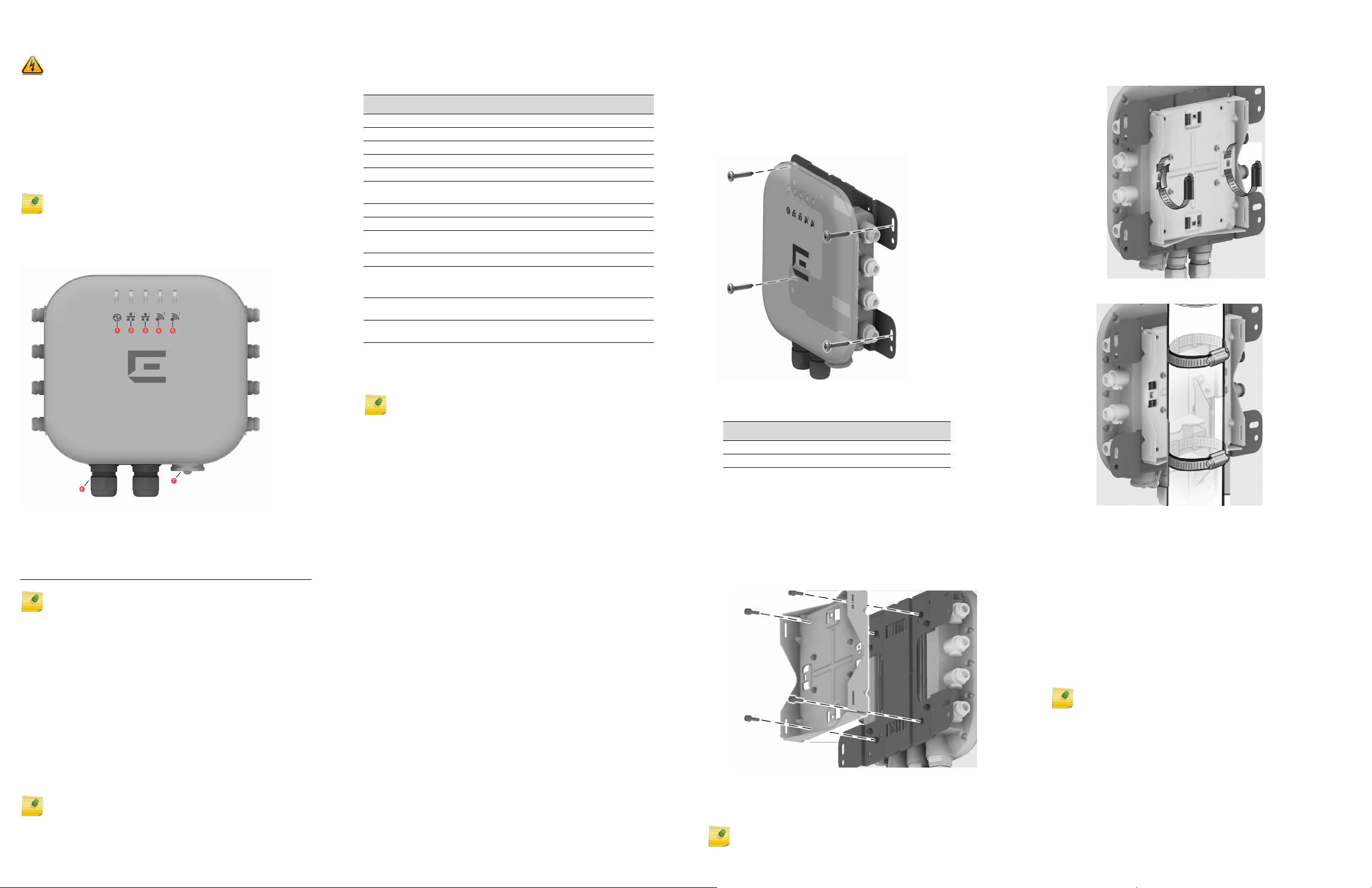
Figure 1 AP3965 Top View
applies to both models.
Unpacking the AP3965
The AP3965 box includes a cardboard separation.
1 Unpack the AP3965 from its carton.
2 Verify the contents of the carton as listed in Ta bl e 1 .
Table 1 Contents of the AP3965
Quantity Item
1 AP3965 Quick Reference
1 WS-AP3965i/e model that you ordered.
Under the cardboard separation:
1 H” shaped bracket that is used for mounting the AP.
1 Metal bracket for attaching the AP to a pole, pipe, or mast.
1 #10AWG ground wire with a ring terminal crimped on it (6 foot
The following hardware is included:
4 Additional Hex nuts for the concrete anchors.
4 Concrete wall anchor assemblies that include the anchors, a
4 Split Washers for the concrete anchors.
4 Cable clamps, all are ½" wide. Two clamps accommodate a 2.5"
8 Screw assemblies, size M4, that include the screws, flat
1 Ground Screw assembly, size M4, that include the screw, star
length)
flat washer, and a hex nut.
maximum diameter pole and two clamps accommodate a
6”-7” diameter pole.
washers, and split washers.
washer, and split washer.
a Use 4 M4 screw assemblies to attach the AP to the “H”
bracket on the side that does not have the PEM standoffs.
b Tighten the four screws to a torque of 12.0 in-lbs.
5 Secure the anchors to the wall, then secure the bracket
to the anchors.
6 If using #10 screws, tighten them to a torque of 25 in-lbs.
If using ¼” screws, tighten them to 45 in-lbs.
Figure 2 AP3965 Wall Mount “H” Bracket
5 Put the metal band around the pole and insert it into the
clamp. Turn the clamp screw clockwise, tightening the
band around the pole.
Figure 4 AP with Mounting Bracket—Horizontal Position
Figure 5 AP3965 Pole Mount—Vertical Pole
1 Status 5 Radio 1 (5 GHz)
2 LAN 1 (Ethernet 1) 6 LAN Ports (POE):
LAN 1 PDE Port
LAN 2 PSE Port output of DC48V, 0.26A
3 LAN 2 (Ethernet 2) 7 Console Port and Reset Button
4 Radio 2 (2.4 GHz) .
War nin g: Always install and torque all LAN and Console
caps properly, regardless of installation site location.
AP3965 models have the following features:
• Radios: 2 radios (2.4 GHz and 5 GHz)
•LEDs: 5 (see Figure 1)
• Power: 802.3at (PoE+) compliant
• The AP3965 supports the 802.11ac and 802.11n wireless
standards, with full backward compatibility with legacy
802.11a, and 802.11b/g devices.The AP3965 with external
antenna connectors supports a variety of antennas.
(External antennas must be ordered separately.)
• The AP3965 interoperates fully with Wireless LAN,
including support for VoWLAN, branch office mode,
guest services, RTLS, availability and mobility features.
• Mounting brackets for a wall or pole mount.
Note: All radio and LAN ports are labeled on the AP3965.
For detailed installation information about the AP3965, see
the ExtremeWireless AP3965i/e Installation Guide.
Optional: You may also need antennas, terminators, or
cables. Refer to
www.extremenetworks.com/support for
product numbers.
Note: Before mounting the AP3965, read the “RF Safety
Distance” on page 2.
Mounting the AP3965
Use these instructions as guidelines for mounting and
connecting the AP3965 easily and safely. The installation of
the AP3965 should be performed by a professional installer
to ensure proper operation and compliance with local
safety guidelines.
Attach the AP3965 to a surface that can support it and
withstand its environment. It can be mounted to a wall,
girder, ceiling, or pole, and the surface material can be
concrete, brick, wood, metal, or plastic.
Positioning the AP for Installation
Mount the AP so that the glands are on the side of the AP
closest to the ground, and not above the plastic cover. You
must provide a 3-inch drip loop on all cables.
Attach the Ground Wire
Use the M4 ground screw assembly, with the star washer, to
attach the ground wire’s ring terminal to the AP. The wire
should be as close to the AP bottom as possible. Tighten
the screw to a torque of 12.0 in-lbs.
Mounting the AP3965 to a Wall
1 Using the mounting bracket as a guide, mark the location
for the mounting screws. The wall bracket provides 8
attachment holes. Use 4 (1 in each corner), Place the
bracket and mark the 4 hole centers.
2 Drill four holes into the wall as follows:
– for installing the AP on a masonry wall, use a 5/16” diameter
bit.
– for other materials, use the appropriate drill for the screws
being used.
3 For masonry installations, drill at least 1/8” [3MM] past
the depth of the screw, or bolt, being used, and place
four anchor assemblies into the holes.
4 Attach the AP to the “H” Bracket:
Mounting the AP3965 to a Pole
1 Determine the diameter of the pole.
Pole Diameter Cable Clamp Size
<= 2.5” [63.5mm], Use small cable clamp.
6” - 7” (178mm) Use large cable clamp
For other pole diameters, provide your own stainless steel cable
clamp. The band must be ½” [12.7mm] wide,
2 Attach the AP to the “H” bracket on the side that does
not have the PEM stand-offs. Tighten the four screws to a
torque of 12.0 in-lbs.
3 Using four M4 screw assemblies, attach the pole bracket
onto the “H” bracket. Tighten the screws to 12 in-lbs.
Figure 3 Attaching Pole Mount to “H” Bracket
4 Attach the cable clamp to the pole bracket. Open the
cable clamp by turning a flat bladed screwdriver
counterclockwise. Then, insert the non-clamp end into
the pole bracket through the holes.
Note: It is easier to install both clamps before attaching to
the pole.
Installing External Antennas
1 Install the external antennas intended for area coverage.
For information about antenna selection and installation,
refer to the External Antenna Site Preparation and
Installation Guide.
2 Attach the external antenna cables to the Standard
Polarity Type-N connectors on the AP3965.
Connecting & Powering the AP3965
You can power up the AP3965 using Power over Ethernet
based on 802.3at (PoE+) compliant switch or PoE+ injector.
• The PoE injector must be 802.3at compliant. The PoE
injector is not provided with the AP.
Note: When the AP3965 is powered by the Power Injector,
the DATA port of the Injector should be connected to a non
PoE switch or, if the switch is PoE capable, PoE must be
DISABLED on the DATA port.
• A waterproof RJ45 connector is provided to connect the
PoE injector to the AP3965. You must connect the RJ45
connector to the RJ45 cable. For instructions, refer to
the ExtremeWireless Outdoor AP3965 Installation Guide.
Notice
Copyright © 2015 Extreme Networks, Inc. All Rights Reserved.
Legal Notices
Extreme Networks, Inc. reserves the right to make changes in specifications
and other information contained in this document and its website without
prior notice. The reader should in all cases consult representatives of
Extreme Networks to determine whether any such changes have been
made.
The hardware, firmware, software or any specifications described or referred
to in this document are subject to change without notice.
Trademarks
Extreme Networks and the Extreme Networks logo are trademarks or
registered trademarks of Extreme Networks, Inc. in the United States and/or
other countries.
All other names (including any product names) mentioned in this document
are the property of their respective owners and may be trademarks or
registered trademarks of their respective companies/owners.
For additional information on Extreme Networks trademarks, please see:
www.extremenetworks.com/company/legal/trademarks/
Documentation & Support
For product support, including documentation, visit:
www.extremenetworks.com/support/
Extreme Networks, Inc.
145 Rio Robles
San Jose, CA 19534
Tel: +1 408-579-2800
Toll-free: +1 888-257-3000
Regulatory and Compliance Information
Federal Communications Commission (FCC)
Notice:
This device complies with Part 15 of the FCC rules. Operation is subject to
the following two conditions: (1) this device may not cause harmful
interference, and (2) this device must accept any interference received,
including interference that may cause undesired operation.
Industry Canada Notice:
This device complies with Industry Canada license-exempt RSS standard(s).
Operation is subject to the following two conditions: (1) this device may not
cause interference, and (2) this device must accept any interference,
including interference that may cause undesired operation of the device.
Le présent appareil est conforme aux CNR d'Industrie Canada applicables
aux appareils radio exempts de licence. L'exploitation est autorisée aux deux
conditions suivantes : (1) l'appareil ne doit pas produire de brouillage, et (2)
l'utilisateur de l'appareil doit accepter tout brouillage radioélectrique subi,
même si le brouillage est susceptible d'en compromettre le fonctionnement.
This radio transmitter (IC: 4141B-4411OAC) has been approved by Industry
Canada to operate with the antenna types listed below with the maximum
permissible gain and required antenna impedance for each antenna type
indicated. Antenna types not included in this list, having a gain greater than
the maximum gain indicated for that type, are strictly prohibited for use with
this device.
Le présent émetteur radio (IC: 4141B-4411AC) a été approuvé par Industrie
Canada pour fonctionner avec les types d'antenne énumérés ci-dessous et
ayant un gain admissible maximal et l'impédance requise pour chaque type
d'antenne. Les types d'antenne non inclus dans cette liste, ou dont le gain
est supérieur au gain maximal indiqué, sont strictement interdits pour
l'exploitation de l'émetteur.:
Antennas for the AP 3965e Antenna Gain
Part No.
(Short Description)
30711 (WS-AO-DQ05120N) 2.4G/5G Sector 5.5 5.5
30712 (WS-AO-5Q04060N) 5G Sector N/A 4
30713 (WS-AO-2Q05060N) 2.4G Sector 5 N/A
30714 (WS-AO-DE07025N) 2.4G/5G Sector 7.5 6.5
30715 (WS-AO-DE13025N) 2.4G/5G Sector 13 12
30716 (WS-AO-5Q05025N) 5G Sector N/A 4.5
30717 (WS-AO-5Q11025N) 5G Sector N/A 11.5
30718 (WS-AO-DE10055N) 2.4G/5G Sector 10.5 7.5
30720 (WS-AO-DE07100N) 2.4G/5G Panel 7 6
30724 (WS-AO-DQ04360N) 2.4/5G Omni 5.5 6
WS-AO-5D23009N
(WS-AO-5D23009N)
Note: All antennas use Standard Polarity Type-N connectors.
Frequency
Band
5G Sector N/A 23
Antenna
Typ e
2.4G
Gain5GGain
The antennas used for this transmitter must be installed to provide a
separation distance of at least 39 cm (150cm for WS-AO-5D23009N) from
all persons and must not be co-located or operating in conjunction with
another antenna or transmitter.
Cet équipement est conforme aux limites d'exposition aux rayonnements IC
établies pour un environnement non contrôlé. Cet équipement doit être
installé et utilisé avec un minimum de 39 cm (150cm pour WS-AO5D23009N) de distance entre la source de rayonnement et votre corps.
Dynamic Frequency Selection (DFS) for devices operating in the bands
5250- 5350 MHz, 5470-5600 MHz and 5650-5725 MHz
Sélection dynamique de fréquences (DFS) pour les dispositifs fonctionnant
dans les bandes 5250-5350 MHz, 5470-5600 MHz et 5650-5725 MHz
This device may not be operated in the band 5150-5250 MHz outdoors. This
band is restricted to indoor use only to reduce potential harmful interference
to co-channel mobile satellite systems.
Ce dispositif ne peut pas être utilisé dans la bande 5150-5250 MHz à
l'extérieur. Cette bande est limitée à une utilisation en intérieur afin de
réduire les interférences nuisibles potentiel de co- canal avec les systèmes
mobiles par satellite.
The maximum antenna gain permitted for devices in the bands 5250-5350
MHz and 5470-5725 MHz shall be such that the equipment still complies
with the e.i.r.p. limit.
le gain maximal d'antenne permis pour les dispositifs utilisant les bandes
5250-5350 MHz et
5470-5725 MHz doit se conformer à la limite de p.i.r.e.
The maximum antenna gain permitted for devices in the band 5725-5850
MHz shall be such that the equipment still complies with the e.i.r.p. limits
specified for point-to-point and non-point-to-point operation as
appropriate.
le gain maximal d'antenne permis (pour les dispositifs utilisant la bande
5725-5850 MHz)
doit se conformer à la limite de p.i.r.e. spécifiée pour l'exploitation point à
point et non point à point, selon le cas.
For product available in the USA/Canada market, only channel 1~11 can be
operated. Selection of other channels is not possible.
Pour les produits disponibles aux États-Unis / Canada du marché, seul le
canal 1 à 11 peuvent être exploités. Sélection d'autres canaux n'est pas
possible.
High-power radars are allocated as primary users (i.e. priority users) of the
bands 5250-5350 MHz and 5650-5850 MHz and that these radars could
cause interference and/or damage to LE-LAN devices.
Les radars à haute puissance sont désignés comme utilisateurs principaux
(c. utilisateurs prioritaires ) des bandes 5250-5350 MHz et 5650-5850 MHz
et que ces radars pourraient provoquer des interférences et / ou
endommager les appareils LE- LAN.
Refer to the ExtremeWireless Outdoor AP3965 Installation Guide, Appendix
B, “Regulatory Information,” for complete regulatory information.
RF Safety Distance
The antennas used for this transmitter must be installed to provide a
separation distance of at least 39 cm (150cm for WS-AO-5D23009N) from
all persons and must not be co-located or operating in conjunction with
another antenna or transmitter.
Safety Guidelines
This section contains notices that you must adhere to ensure your personal
safety and to prevent any damage to the equipment.
Grounding Warning:
War nin g: To operate the ExtremeWireless Outdoor AP3965 safely,
the chassis ground connector must have a suitable cable connected.
Do not use the ExtremeWireless Outdoor AP3965 without a ground
cable connected.
Qualified Personnel:
Electrical Hazard: Only qualified personnel should perform
installation procedures. Within the context of the safety notes in this
documentation qualified persons are defined as persons who are
authorized to commission, ground and label devices, systems and
circuits in accordance with established safety practices and
standards. A qualified person understands the requirements and
risks involved with installing outdoor electrical equipment in
accordance with national codes.
Lightning Protection Warning:
War nin g: Antennas installed outdoors must be within the area
covered by a lightning protection system. Make sure that all
conducting systems entering from outdoors can be protected by a
lightning protection potential equalization system.When
implementing your lightning protection concept, make sure you
adhere to the VDE 0182 or IEC 62305 standard.
The AP3965 has a built-in lightning protector; no external lightning
protector is required. You must, however, note that the lightning
protector is not an adequate protection against a lightning strike.
The lightening protector only works within the framework of a
comprehensive lightning protection concept. If you have questions,
ask a qualified specialist company.
European Waste Electrical and Electronic
Equipment (WEEE) Notice
In accordance with Directive 2012/19/EU of the European Parliament on waste electrical
and electronic equipment (WEEE):
1 The symbol above indicates that separate collection of electrical and electronic
equipment is required.
2 When this product has reached the end of its serviceable life, it cannot be disposed of
as unsorted municipal waste. It must be collected and treated separately.
3 It has been determined by the European Parliament that there are potential negative
effects on the environment and human health as a result of the presence of hazardous
substances in electrical and electronic equipment.
4 It is the users’ responsibility to utilize the available collection system to ensure WEEE
is properly treated.
For information about the available collection system, please contact Extreme
Customer Support at 353 61 705500 (Ireland).
NCC Statement
(1) 「經型式認證合格之低功率射頻電機,非經許可,公司、商號或使用者均不得擅
自變更頻率、加大功率或變更原設計之特性及功能」。
(2) 「低功率射頻電機之使用不得影響飛航安全及干擾合法通信;經發現有干擾現象
時,應立即停用,並改善至無干擾時方得繼續使用。前項合法通信,指依電
信法規定作業之無線電通信。低功率射頻電機須忍受合法通信或工業、科學
及醫療用電波輻射性電機設備之干擾」。
(3) 「電磁波曝露量 MPE 標準值 1mW/cm
cm」。
(4) 「本器材須經專業工程人員安裝及設定,始得設置使用,且不得直接販售給一般
消費者
2
,本產品使用時建議應距離人體:39
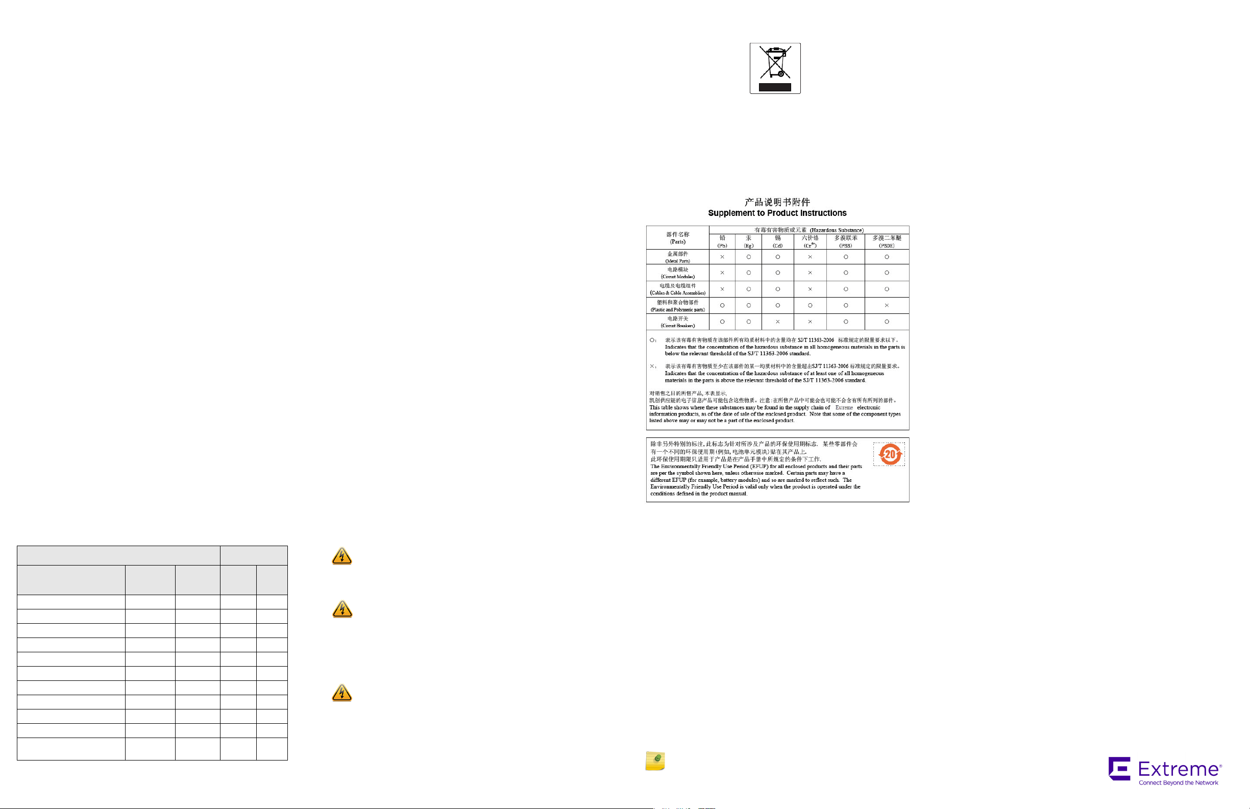
Hazardous Substances
This product complies with the requirements of Directive 2011/65/EU of the European
Parliament and of the Council of 8 June 2011 on the restriction of the use of certain
hazardous substances in electrical and electronic equipment.
Declaration of Conformity in Languages of the
European Community
Hereby, Extreme Networks, Inc. declares that the radio equipment type Wireless LAN
Access Point is in compliance with Directive 1999/5/EC. The full text of the EU declaration
of conformity is available at the following Internet address:
http://www.extremenetworks.com/
Note: Changes or modifications made to this device which are not
expressly approved by the party responsible for compliance could
void the user’s authority to operate the equipment.
ExtremeWireless
TM
Access Points
Quick Reference
P/N 31016 WS-AP3965i-FCC
P/N 31017 WS-AP3965i-ROW
P/N 31018 WS-AP3965e-FCC
P/N 31019 WS-AP3965e-ROW
Federal Communication Commission Interference Statement
This equipment has
for a Class A digital device, pursuant to part 15 of the FCC Rules.
These limits are designed to provide reasonable protection against
harmful interference when the equipment is operated in a
commercial environment. This equipment generates, uses, and can
radiate radio frequency energy and, if not installed and used in
accordance with the instruction manual, may cause harmful
interference to radio communications. Operation of this equipment
in a residential area is likely to cause harmful interference in which
case the user will be required to correct the interference at his own
expense.
P/N 9034916 Rev.01
been tested and found to comply with the limits
 Loading...