

Extreme Networks 3626, 3650 Quick Install Manual

Depending on your hardware model, your switch may
appear different than the figures shown in this guide.
Ethernet Routing
Switch 3600 Series
Quick Install Guide
Confirm that you have the tools and package contents
as follows:
Tools Required:
• Phillips #2 screwdriver
• Console cable
Package Contents:
Before you start
1. Provide the equivalent of 1U of vertical rack space for each
3626 or 3650 model in an EIA or IEC-standard 19-inch
(48.2-centimeter) equipment rack.
2. Ensure that the equipment rack is stable and securely
attached to a permanent structure.
3. Ground the rack to the same grounding electrode used by
the power service in the area. The ground path must be
permanent and must not exceed 1 Ohm of resistance from
the rack to the grounding electrode. Extreme Networks
recommends using a filter or surge suppressor.
Product
Number
Name
AL2011020-E6
AL2011022-E6
DB-9 RED TO
RJ-45 ADAPTOR
RJ-45/DB-9
CONSOLE CABLE
DB-9 RED TO RJ-45 SERIAL PORT.
Can be used with standard Category 5
cable to connect DB-9 FEMALE serial
port on PCs.
1.8m cable with DB-9 Female for
terminal/PC on one end and RJ-45
for device console port connectivity
on the other
Description
Note: Extreme Networks does not supply the bolts used to
secure the switch to the rack. Ensure you obtain the
appropriate bolts to secure the switch to your specific rack
before you begin.
1. Attach a bracket to each side of the switch.
The Ethernet Routing Switch 3600 Series provides fail-safe
stackability. You can connect up to eight ERS 3600 Series
devices in a stack to provide uninterrupted connectivity for up
to 224 to 416 ports. You can manage the stack as a single unit.
To install/add a unit to a stack, you must change the default
mode from standalone to stacking mode and reboot the unit. See
Installing Ethernet Routing Switch 3600 Series for more details.
The Ethernet Routing Switch 3600 Series back panel provides a
Base Unit switch. The Base Unit Switch is used to designate the
base unit in a stack. When set to the RIGHT position, this unit
acts as the Base Unit for the stack.
The Ethernet Routing Switch 3600 Series provides a Cascade
Down port, and a Cascade Up ports on the front panel
for stacking purposes as shown below:
• Stacking cables
Product
Number
AA1403018-E6
AA1403019-E6
AA1403020-E6
10m (Active Copper Cable) SFP+ direct attach cable
3.0m (Active Copper Cable) SFP+ direct attach cable
5.0m (Active Copper Cable) SFP+ direct attach cable
Description
2. Attach a bracket to each side of the switch.
3. Slide the switch into the rack. Insert and tighten the
rack-mount screws.
4. Verify that the switch is securely fastened to the rack.
Cascade Down and Cascade Up ports – used to connect a
switch to the next unit in a stack through a cascade cable.
Connect one end of the Cascade Down cable to the
Cascade Up port of the next switch in the stack (shown in
the three-switch stack connection block diagram below):
1
2
3
1 – Base Unit
2 – Cascade/Stacking Cable
3 – Cascade/Stacking cable
(Return cable to make stack
resilient. Use longer stack
cable if required).
To create a stack connection, order the appropriate cascade cables
to ensure fail-safe stacking. For stacking three or more units
(maximum eight units per stack), order the applicable 3.0 m, 5.0 m,
or 10 m cables as applicable (see “Stacking cables”).
1. Ensure all the switches for the stack are rack mounted.
2. Slide the Base Unit Select switches on the on the back of the
units to the appropriate position, depending on whether they are
a base unit or a non-base unit:
• Base Unit – Slide the Base Unit Select switch to the RIGHT.
• Non-Base Unit – Slide the Base Unit Select switch to the LEFT.
Because stack parameters are associated with the base unit, the
physical stack order depends on the base unit position and
whether you configure the stack cascade up (stack up) or cascade
down (stack down). This designation depends on the stack cabling
arrangement.
IMPORTANT: Extreme Networks recommends you to use the
Cascade Down configuration.
• Unpack the Ethernet Routing Switch 3600 Series.
• Observe ESD precautions when unpacking.
700512588
SFP+ to SFP+, 10G, passive, 0.5M
700512589
SFP+ to SFP+, 10G, passive, 1.0M
When you install the switch in the network, ensure you use the
following cables:
• Category 5E or higher specification cabling should be used
for 1 Gbps/1000 Mbps operation
• RJ-45 console port cables and adaptors are as follows:
1
3
2
1. Ethernet Routing Switch 3600 Series
2. Rack-mounting hardware that includes:
• Rack-mount brackets (2)
• Screws to attach brackets to the switch (8)
• Screws to attach the switch to the equipment
rack (3 x 4).
3. Rubber footpads (ERS 3626GTS-PWR+ only)
4. Documentation that includes Quick Install poster and
the Regulatory Document
Note: Be sure to order Direct Attach cables and SFP or
SFP+ Transceivers if required.
Note: Be sure to order the correct power cord for your region.
1
Tools Required and Package Contents
3a
Rack mouting
4
Stacking
2a
Unpack equipment
2b
(Optional) Prepare the rack
2c
Install the Switch
For information about installing an ERS 3626GTS-PWR+ on a
table or shelf, see Installing the Ethernet Routing Switch
3600 Series.
3b
Table mouting
Connect the AC power cord to the back of the switch, and
then plug the other end of the cord into an AC power outlet.
Warning: You must use a power cord set approved for the
ERS 3600 Series switch and the power receptacle type for
your country.
a. Connect the console cable from the terminal to the console
port of the switch to allow initial configuration. Any terminal
or PC with the appropriate terminal emulator can be used
as the management station.
To connect to the switch
console port, you require a
console cable with an RJ-45
connector to match the
console port on the switch.
CLI Quickstart welcome screen
################################################################
Welcome to the ERS3600 setup utility.
You will be requested to provide the switch basic connectivity
settings. After entering the requested info, the configuration
will be applied and stored into the switch NVRAM.
Once the basic connectivity settings are applied, additional
configuration can be done using the available management interfaces.
Use Ctrl+C to abort the configuration at any time.
################################################################
Please provide the Quick Start VLAN <1-4094> [1]:
Please provide the in-band IP Address[192.0.2.3]:
Please provide the in-band sub-net mask[255.255.255.0]:
Please provide the Default Gateway[192.0.2.4]:
Please provide the Read-Only Community String[**********]:
Please provide the Read-Write Community String[**********]:
Please provide the in-band IPV6 Address/Prefix_length[::/0]:
Please provide the in-band IPV6 Default Gateway[::]:
################################################################
Basic stack parameters have now been configured and saved.
################################################################
1. Connect a Laptop/PC to any Ethernet port and ensure that
the PC has an IP address configured within the same IP
subnet as the switch management IP address.
2. Start your web browser, such as Internet Explorer or Firefox.
3. Enter switch management IP address in the URL field and
press Enter (for example; 192.0.2.1).
4. The switch summary screen appears on your browser. Use
the navigation tree on the left to select switch configuration
options.
Note: You do not need login credentials.
CLI boot and factory default commands:
boot – reboot the switch
boot default – reboot and use the factory default
configuration
restore factory default – reset the switch to factory
default configuration
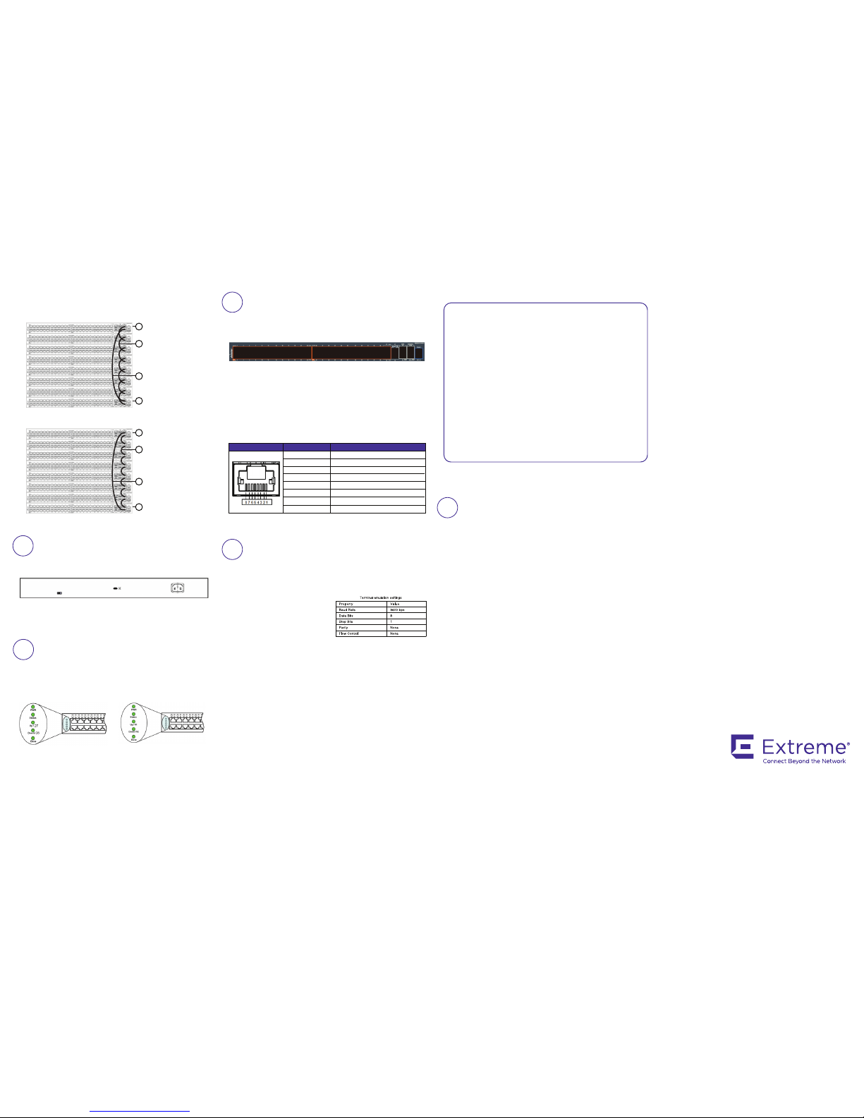
The console port is the RJ-45 port shown with a blue border
outline on the front of your ERS 3600 Series switch (note the
orientation). The port is labeled Console.
Use an RJ-45 to DB-9 cable to connect the switch console
port to your management terminal. Extreme Networks
recommends that you use the RJ-45 Console Cable part
number: AL2011022-E6. Alternatively, a DB-9 to RJ-45
adapter or other suitable console cables can be used – the
maximum length of a console cable is 25 feet (8.3 meters).
The following table describes the RJ-45 console port pin-out
information. You can use the pin-out information to verify or
create a console cable for use with your maintenance
terminal.
Recommended reading
To obtain additional documentation references, go to
http://www.extremenetworks.com/support/documentation/
and download the following ERS 3600 documents:
• Locating Documentation
• Documentation Reference
• Installing ERS 3600
• Installation Job Aid
• Release Notes
3. Connect stacking cables as required for a Cascade Up (stack up)
or Cascade Down (stack down) configuration as shown below:
Cascade Down (stack down) configuration
1 = Base unit
2 = Cascade/Stack Cable
3 = Cascade/Stack Cable
(Return cable to make
stack resilient. Use longer
stack cable if required.)
4 = Last unit
4
2
3
1
Cascade Up (stack up) configuration
1 = Base unit
2 = Cascade/Stack Cable
3 = Cascade/Stack Cable
(Return cable to make
stack resilient. Use longer
stack cable if required.)
4 = Last unit
4
2
3
1
Check the front-panel LEDs as the device powers on to be
sure the PWR LED is lit. If not, check if the power cord is
plugged in correctly.
The ERS 3600 Series switches begin switching data after
the switch is powered up and has loaded the agent code
software, which is indicated by both the PWR and Status
LEDs being lit solid green.
Connector Pin Number Signal
1
2
3
4
5
6
7
8
RTS (ready to send) – optional
DTR (data terminal ready) – optional
TXD (transmit data) – mandatory
GND (ground) – mandatory
DCD (carrier detect) – optional
RXD (receive data) – mandatory
DSR (data set ready) – optional
CTS (clear to send) – optional
b. Set the terminal protocol on the terminal or terminal
emulation program to VT100 or VT100/ANSI.
c. Connect to the switch using the terminal or terminal
emulation application.
d. The Extreme Networks switch banner appears when you
connect to the switch through the Console port. There is no
default password for the switch for CLI console access.
Enter Ctrl+Y and type the following CLI commands:
• enable
• install
e. The CLI Quickstart welcome screen helps you enter the
information requested at each prompt.
Note: The ERS 3600 uses the default IP address of
192.168.1.1/24 if the switch does not get its IP address from
another source.
ERS3626GTS/ERS3626GTS-PWR+
ERS3650GTS/ERS3650GTS-PWR+
5
Powering Up
6
7
Console Port pin assignments
8
Setting IP parameters using the console
port and CLI QuickStart
9
Connecting to the ERS 3600 embedded Web UI
6480 Via Del Oro
San Jose, CA 95119
Tel: +1 408-579-2800
Toll-free: +1 888-257-3000
WWW.EXTREMENETWORKS.COM
Poster part number: 700513176 Rev.02
NN47213-300 02.03
 Loading...