

Extreme Networks 210-12p-GE2, 210-24t-GE2, 210-12t-GE2, 210-48t-GE4, 210-24p-GE2 Hardware Installation Manual
...
ExtremeSwitching 210 and
220 Series Switches:
Hardware Installation Guide
122039-00
Published May 2017

Copyright © 2017 Extreme Networks, Inc. All rights reserved.
Legal Notice
Extreme Networks, Inc. reserves the right to make changes in specifications and other information
contained in this document and its website without prior notice. The reader should in all cases
consult representatives of Extreme Networks to determine whether any such changes have been
made.
The hardware, firmware, software or any specifications described or referred to in this document
are subject to change without notice.
Trademarks
Extreme Networks and the Extreme Networks logo are trademarks or registered trademarks of
Extreme Networks, Inc. in the United States and/or other countries.
All other names (including any product names) mentioned in this document are the property of
their respective owners and may be trademarks or registered trademarks of their respective
companies/owners.
For additional information on Extreme Networks trademarks, please see:
www.extremenetworks.com/company/legal/trademarks
Software Licensing
Some software files have been licensed under certain open source or third-party licenses. Enduser license agreements and open source declarations can be found at:
www.extremenetworks.com/support/policies/software-licensing
Support
For product support, phone the Global Technical Assistance Center (GTAC) at 1-800-998-2408
(toll-free in U.S. and Canada) or +1-408-579-2826. For the support phone number in other
countries, visit: http://www.extremenetworks.com/support/contact/
For product documentation online, visit: https://www.extremenetworks.com/documentation/

Table of Contents
Preface......................................................................................................................................... 5
Audience....................................................................................................................................................................................5
Conventions.............................................................................................................................................................................5
Providing Feedback to Us................................................................................................................................................ 6
Getting Help.............................................................................................................................................................................7
Related Publications............................................................................................................................................................ 7
Chapter 1: ExtremeSwitching 210 and 220 Series Switches................................................9
Overview of the ExtremeSwitching 210 Series Switches.................................................................................10
Overview of the ExtremeSwitching 220 Series Switches................................................................................16
ExtremeSwitching 210 and 220 Series Switch LEDs.........................................................................................23
Pluggable Interfaces for ExtremeSwitching Switches......................................................................................23
Chapter 2: External Power Supplies...................................................................................... 25
RPS-150XT Redundant Power Supply......................................................................................................................25
RPS-500p Redundant Power Supply.......................................................................................................................27
Installing External Power Supplies............................................................................................................................. 28
Chapter 3: Installing Your 210 or 220 Switch...................................................................... 36
Safety Considerations for Installing Switches...................................................................................................... 37
Pre-installation Requirements...................................................................................................................................... 37
Attaching a 24- or 48-Port Switch to a Rack.......................................................................................................38
Mounting 12-Port Switches............................................................................................................................................39
Installing a Switch on a Desktop or Other Flat Surface.................................................................................. 48
Installing Optional Components................................................................................................................................. 49
Connecting Power to the Switch................................................................................................................................50
Connecting Network Interface Cables.....................................................................................................................50
Chapter 4: Building Stacks..................................................................................................... 52
Planning to Create Your Stack..................................................................................................................................... 52
Setting up the Physical Stack.......................................................................................................................................55
Managing Stacks.................................................................................................................................................................58
Chapter 5: Basic Configuration for Your Switch................................................................. 60
First-time Network Connection and Configuration.......................................................................................... 60
Appendix A: Safety Information............................................................................................63
Considerations Before Installing................................................................................................................................. 63
General Safety Precautions...........................................................................................................................................64
Maintenance Safety...........................................................................................................................................................64
Cable Routing for LAN Systems................................................................................................................................. 65
Selecting Power Supply Cords.................................................................................................................................... 65
Battery Replacement and Disposal...........................................................................................................................66
Battery Warning - Taiwan...............................................................................................................................................66
Fiber Optic Ports and Optical Safety.......................................................................................................................66
Appendix B: Technical Specifications...................................................................................68
ExtremeSwitching 210 and 220 Switches.............................................................................................................. 68
RPS-150XT Redundant Power Supply Technical Specifications................................................................. 74
RPS-500p Redundant Power Supply Technical Specifications...................................................................76
ExtremeSwitching 210 and 220 Series Switches: Hardware Installation Guide 3

Table of Contents
Power Cord Requirements for AC-Powered Switches and AC Power Supplies..................................77
Index.......................................................................................................................................... 79
ExtremeSwitching 210 and 220 Series Switches: Hardware Installation Guide 4

Preface
This guide provides the instructions and supporting information needed to install the following Extreme
Networks® products:
210 Series switches:
•
ExtremeSwitching 210-12t-GE2 switch
•
ExtremeSwitching 210-12p-GE2 switch
•
ExtremeSwitching 210-24t-GE2 switch
•
ExtremeSwitching 210-24p-GE2 switch
•
ExtremeSwitching 210-48t-GE4 switch
•
ExtremeSwitching 210-48p-GE4 switch
•
220 Series switches:
•
ExtremeSwitching 220-12t-10GE2 switch
•
ExtremeSwitching 220-12p-10GE2 switch
•
ExtremeSwitching 220-24t-10GE2 switch
•
ExtremeSwitching 220-24p-10GE2 switch
•
ExtremeSwitching 220-48t-10GE4 switch
•
ExtremeSwitching 220-48p-10GE4 switch
•
The guide includes information about site preparation, switch functionality, and switch operation.
Audience
This guide is intended for use by network administrators responsible for installing and setting up
network equipment. It assumes a basic working knowledge of:
Local area networks (LANs)
•
Ethernet concepts
•
Ethernet switching and bridging concepts
•
Routing concepts
•
SNMP (Simple Network Management Protocol)
•
Basic equipment installation procedures
•
Note
If the information in an installation note or release note shipped with your Extreme Networks
equipment diers from the information in this guide, follow the installation or release note.
Conventions
This section discusses the conventions used in this guide.
Text Conventions
The following tables list text conventions that are used throughout this guide.
ExtremeSwitching 210 and 220 Series Switches: Hardware Installation Guide 5
Table 1: Notice Icons
Icon Notice Type Alerts you to...
General Notice Helpful tips and notices for using the product.
Note Important features or instructions.
Caution Risk of personal injury, system damage, or loss of data.
Warning Risk of severe personal injury.
New This command or section is new for this release.
Preface
Table 2: Text Conventions
Convention Description
Screen displays
The words enter and
type
[Key] names Key names are written with brackets, such as [Return] or [Esc]. If you must press two
Words in italicized type Italics emphasize a point or denote new terms at the place where they are defined in
This typeface indicates command syntax, or represents information as it appears on the
screen.
When you see the word “enter” in this guide, you must type something, and then press
the Return or Enter key. Do not press the Return or Enter key when an instruction
simply says “type.”
or more keys simultaneously, the key names are linked with a plus sign (+). Example:
Press [Ctrl]+[Alt]+[Del]
the text. Italics are also used when referring to publication titles.
Terminology
When features, functionality, or operation is specific to a switch family, such as ExtremeSwitching™ or
Summit®, the family name is used. Explanations about features and operations that are the same across
all product families simply refer to the product as the switch.
Providing Feedback to Us
We are always striving to improve our documentation and help you work better, so we want to hear
from you! We welcome all feedback but especially want to know about:
Content errors or confusing or conflicting information.
•
Ideas for improvements to our documentation so you can find the information you need faster.
•
Broken links or usability issues.
•
ExtremeSwitching 210 and 220 Series Switches: Hardware Installation Guide 6

If you would like to provide feedback to the Extreme Networks Information Development team about
this document, please contact us using our short online feedback form. You can also email us directly at
internalinfodev@extremenetworks.com.
Getting Help
If you require assistance, contact Extreme Networks using one of the following methods:
GTAC (Global Technical Assistance Center) for Immediate Support
•
Phone: 1-800-998-2408 (toll-free in U.S. and Canada) or +1 408-579-2826. For the support
•
phone number in your country, visit: www.extremenetworks.com/support/contact
Email: support@extremenetworks.com. To expedite your message, enter the product name or
•
model number in the subject line.
GTAC Knowledge — Get on-demand and tested resolutions from the GTAC Knowledgebase, or
•
create a help case if you need more guidance.
The Hub — A forum for Extreme customers to connect with one another, get questions answered,
•
share ideas and feedback, and get problems solved. This community is monitored by Extreme
Networks employees, but is not intended to replace specific guidance from GTAC.
Support Portal — Manage cases, downloads, service contracts, product licensing, and training and
•
certifications.
Preface
Before contacting Extreme Networks for technical support, have the following information ready:
Your Extreme Networks service contract number and/or serial numbers for all involved Extreme
•
Networks products
A description of the failure
•
A description of any action(s) already taken to resolve the problem
•
A description of your network environment (such as layout, cable type, other relevant environmental
•
information)
Network load at the time of trouble (if known)
•
The device history (for example, if you have returned the device before, or if this is a recurring
•
problem)
Any related RMA (Return Material Authorization) numbers
•
Related Publications
200 Series Documentation
ExtremeSwitching 210 and 220 Series Switches: Hardware Installation Guide
•
ExtremeSwitching 200 Series: Administration Guide
•
ExtremeSwitching 200 Series: Command Reference Guide
•
Other Documentation
Extreme Hardware/Software Compatibility and Recommendation Matrices
•
Extreme Networks Pluggable Transceivers Installation Guide
•
Environmental Guidelines for ExtremeSwitching Products
•
ExtremeSwitching 210 and 220 Series Switches: Hardware Installation Guide 7

Open Source Declarations
Some software files have been licensed under certain open source licenses. More information is
available at: www.extremenetworks.com/support/policies/software-licensing
Preface
ExtremeSwitching 210 and 220 Series Switches: Hardware Installation Guide 8

1 ExtremeSwitching 210 and 220
Series Switches
Overview of the ExtremeSwitching 210 Series Switches
Overview of the ExtremeSwitching 220 Series Switches
ExtremeSwitching 210 and 220 Series Switch LEDs
Pluggable Interfaces for ExtremeSwitching Switches
The ExtremeSwitching 210 and 220 series switches are compact enclosures 1.75 inches high (1 U). Each
switch model provides 12, 24, or 48 high-density copper or fiber optic ports operating at speeds up to
10 Gbps. PoE connections are available on some models.
The 220 series 24-port and 48-port switches make provision for redundant power supplies.
Model numbers for the switches use the following format:
Series Number_of_Ports Port_Type SFP_Ports
where:
Series = The switch series – either 210 or 220
•
Number_of_Ports = The number of front-panel I/O ports, for example 24 or 48.
•
Port_Type = Either t (copper) or p (copper providing Power over Ethernet, or PoE).
•
SFP_Ports = The number and type of additional SFP or SFP+ ports that can transmit at 1 GbE or
•
10GbE speeds
For example, the 220-48p-10GE4 switch:
Is part of the 220 series.
•
Has 48 ports of copper providing PoE.
•
Has four ports that can transmit at 10GbE speed.
•
The following sections provide detailed descriptions of the switches:
ExtremeSwitching 210-12t-GE2 switch
•
ExtremeSwitching 210-12p-GE2 switch
•
ExtremeSwitching 210-24t-GE2 switch
•
ExtremeSwitching 210-24p-GE2 switch
•
ExtremeSwitching 210-48t-GE4 switch
•
ExtremeSwitching 210-48p-GE4 switch
•
ExtremeSwitching 220-12t-10GE2 switch
•
ExtremeSwitching 220-12p-10GE2 switch
•
ExtremeSwitching 220-24t-10GE2 switch
•
ExtremeSwitching 220-24p-10GE2 switch
•
ExtremeSwitching 210 and 220 Series Switches: Hardware Installation Guide 9

ExtremeSwitching 210 and 220 Series Switches
ExtremeSwitching 220-48t-10GE4 switch
•
ExtremeSwitching 220-48p-10GE4 switch
•
Overview of the ExtremeSwitching 210 Series Switches
The ExtremeSwitching 210 series switches are 12-, 24, or 48-port switches that provide 1-gigabit
Ethernet connectivity using fixed 10/100/1000BASE-T RJ45 ports and installable SFP optical modules.
The ExtremeSwitching 210 series base models are described in the following sections:
ExtremeSwitching 210-12t-GE2 Switch Ports and Slots on page 10
•
ExtremeSwitching 210-12p-GE2 Switch Ports and Slots on page 11
•
ExtremeSwitching 210-24t-GE2 Switch Ports and Slots on page 12
•
ExtremeSwitching 210-24p-GE2 Switch Ports and Slots on page 13
•
ExtremeSwitching 210-48t-GE4 Switch Ports and Slots on page 14
•
ExtremeSwitching 210-48p-GE4 Switch Ports and Slots on page 15
•
Using a serial console port on the front panel of the switch, you can connect a terminal and perform
local management. An Ethernet management port can be used to connect the system to a parallel
management network for administration. Alternatively, you can use an Ethernet cable to connect this
port directly to a laptop to view and locally manage the switch configuration. The Ethernet
management port supports 10/100 Mbps speeds.
The 12-port switches have a small form factor that allows you to install two switches side-by-side in a
standard equipment rack.
Switch cooling is provided by one, two, or three non-replaceable fan modules with side-to-side airflow.
AC power is supplied by a built-in power supply unit that is not user-replaceable.
ExtremeSwitching 210-12t-GE2 Switch Ports and Slots
The ExtremeSwitching 210-12t-GE2 switch ports and slots include:
12 10/100/1000BASE-T ports (ports 1–12) that provide 1 GbE connectivity
•
Two dedicated 1 GbE SFP ports (ports 13–14)
•
Ethernet management port (10/100BASE-T)
•
Serial console port used to connect a terminal and perform local management
•
LEDs to indicate switch operating conditions
•
For a description of the LEDs and their operation, see ExtremeSwitching 210 and 220 Series Switch
LEDs on page 23.
ExtremeSwitching 210 and 220 Series Switches: Hardware Installation Guide 10
ExtremeSwitching 210 and 220 Series Switches
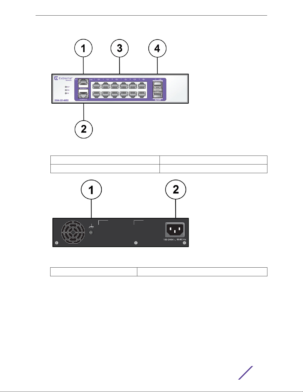
Figure 1: ExtremeSwitching 210-12t-GE2 Switch Front Panel
1 = Ethernet management port 3 = 10/100/1000BASE-T ports
2 = Console port 4 = SFP ports
Figure 2: ExtremeSwitching 210-12t-GE2 Switch Rear Panel
1 = Grounding point
2 = AC power input connector
ExtremeSwitching 210-12p-GE2 Switch Ports and Slots
The ExtremeSwitching 210-12p-GE2 switch ports and slots include:
12 10/100/1000BASE-T PoE+ ports (ports 1–12) that provide 1 GbE connectivity
•
Two dedicated 1 GbE SFP ports (ports 13–14)
•
Ethernet management port (10/100BASE-T)
•
Serial console port used to connect a terminal and perform local management
•
LEDs to indicate switch operating conditions
•
ExtremeSwitching 210 and 220 Series Switches: Hardware Installation Guide 11
ExtremeSwitching 210 and 220 Series Switches
For a description of the LEDs and their operation, see ExtremeSwitching 210 and 220 Series Switch
LEDs on page 23.
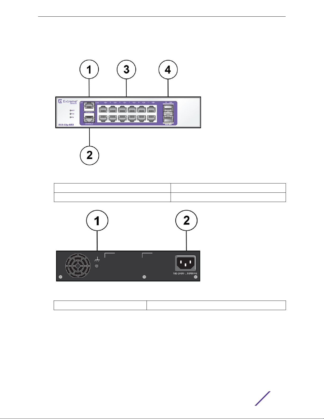
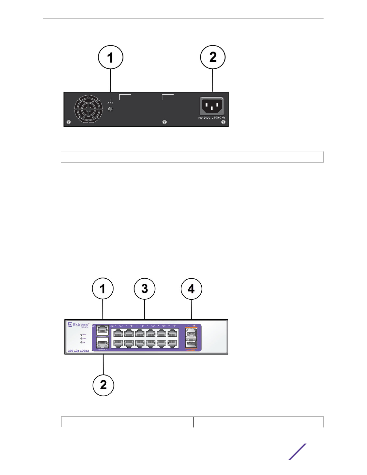
Figure 3: ExtremeSwitching 210-12p-GE2 Switch Front Panel
1 = Ethernet management port 3 = 10/100/1000BASE-T ports
2 = Console port 4 = SFP ports
Figure 4: ExtremeSwitching 210-12p-GE2 Switch Rear Panel
1 = Grounding point
2 = AC power input connector
ExtremeSwitching 210-24t-GE2 Switch Ports and Slots
The ExtremeSwitching 210-24t-GE2 switch ports and slots include:
24 10/100/1000BASE-T ports (ports 1–24) that provide 1 GbE connectivity
•
Two dedicated 1 GbE SFP ports (ports 25–26)
•
Ethernet management port (10/100BASE-T)
•
ExtremeSwitching 210 and 220 Series Switches: Hardware Installation Guide 12
ExtremeSwitching 210 and 220 Series Switches
Serial console port used to connect a terminal and perform local management
•
LEDs to indicate switch operating conditions
•
For a description of the LEDs and their operation, see ExtremeSwitching 210 and 220 Series Switch
LEDs on page 23.
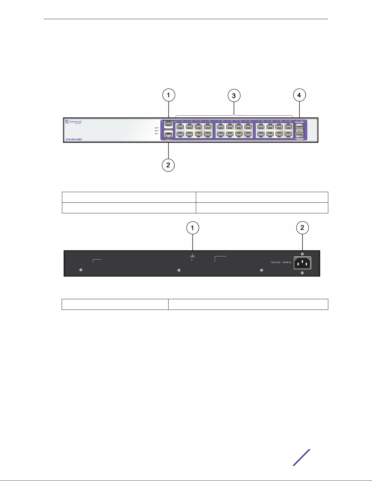
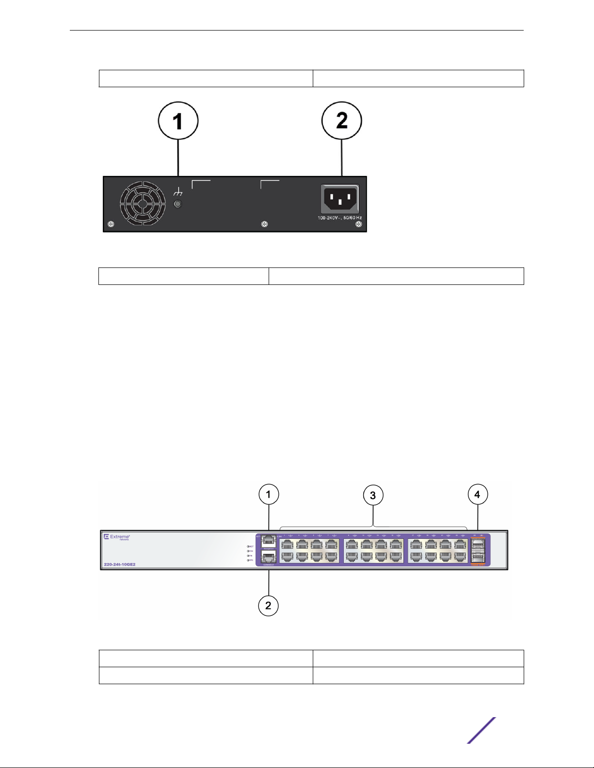
Figure 5: ExtremeSwitching 210-24t-GE2 Switch Front Panel
1 = Ethernet management port 3 = 10/100/1000BASE-T ports
2 = Console port 4 = SFP ports
Figure 6: ExtremeSwitching 210-24t-GE2 Switch Rear Panel
1 = Grounding point
2 = AC power input connector
ExtremeSwitching 210-24p-GE2 Switch Ports and Slots
The ExtremeSwitching 210-24p-GE2 switch ports and slots include:
24 10/100/1000BASE-T PoE+ ports (ports 1–24) that provide 1 GbE connectivity
•
Two dedicated 1 GbE SFP ports (ports 25–26)
•
Ethernet management port (10/100BASE-T)
•
Serial console port used to connect a terminal and perform local management
•
LEDs to indicate switch operating conditions
•
For a description of the LEDs and their operation, see ExtremeSwitching 210 and 220 Series Switch
LEDs on page 23.
ExtremeSwitching 210 and 220 Series Switches: Hardware Installation Guide 13
ExtremeSwitching 210 and 220 Series Switches
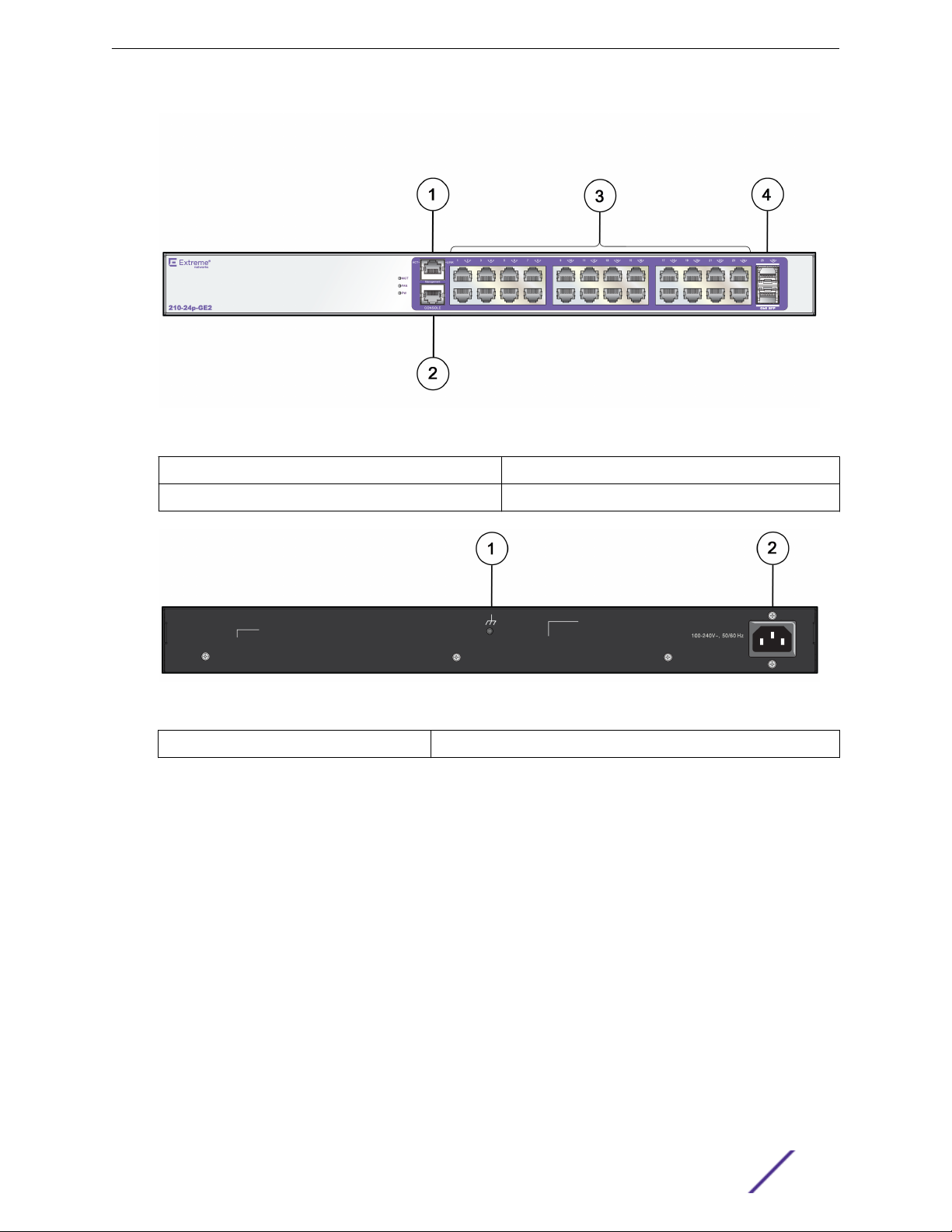
Figure 7: ExtremeSwitching 210-24p-GE2 Switch Front Panel
1 = Ethernet management port 3 = 10/100/1000BASE-T ports
2 = Console port 4 = SFP ports
Figure 8: ExtremeSwitching 210-24p-GE2 Switch Rear Panel
1 = Grounding point
2 = AC power input connector
ExtremeSwitching 210-48t-GE4 Switch Ports and Slots
The ExtremeSwitching 210-48t-GE4 switch ports and slots include:
48 10/100/1000BASE-T ports (ports 1–48) that provide 1 GbE connectivity
•
Four dedicated 1 GbE SFP ports (ports 49–52)
•
Ethernet management port (10/100BASE-T)
•
Serial console port used to connect a terminal and perform local management
•
LEDs to indicate switch operating conditions
•
For a description of the LEDs and their operation, see ExtremeSwitching 210 and 220 Series Switch
LEDs on page 23.
ExtremeSwitching 210 and 220 Series Switches: Hardware Installation Guide 14
ExtremeSwitching 210 and 220 Series Switches
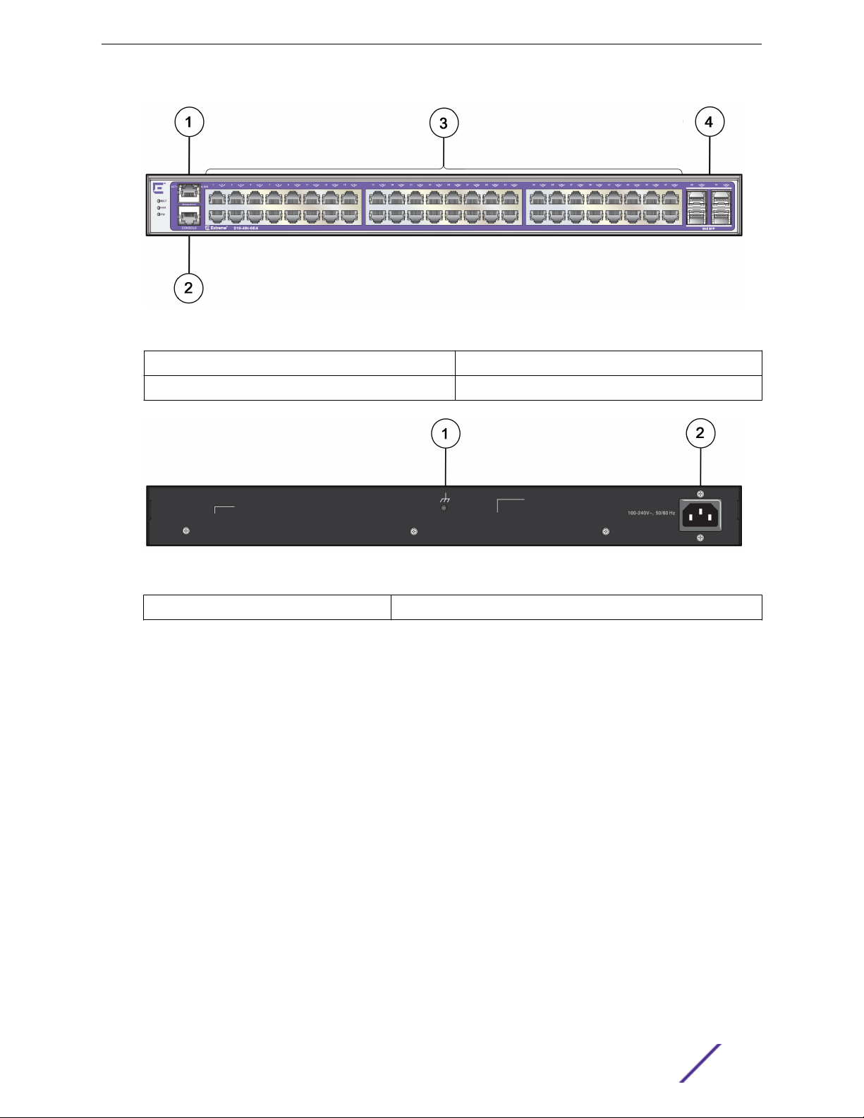
Figure 9: ExtremeSwitching 210-48t-GE4 Switch Front Panel
1 = Ethernet management port 3 = 10/100/1000BASE-T ports
2 = Console port 4 = SFP ports
Figure 10: ExtremeSwitching 210-48t-GE4 Switch Rear Panel
1 = Grounding point
2 = AC power input connector
ExtremeSwitching 210-48p-GE4 Switch Ports and Slots
The ExtremeSwitching 210-48p-GE4 switch ports and slots include:
48 10/100/1000BASE-T PoE+ ports (ports 1–48) that provide 1 GbE connectivity
•
Four dedicated 1 GbE SFP ports (ports 49–52)
•
Ethernet management port (10/100BASE-T)
•
Serial console port used to connect a terminal and perform local management
•
LEDs to indicate switch operating conditions
•
For a description of the LEDs and their operation, see ExtremeSwitching 210 and 220 Series Switch
LEDs on page 23.
ExtremeSwitching 210 and 220 Series Switches: Hardware Installation Guide 15
ExtremeSwitching 210 and 220 Series Switches
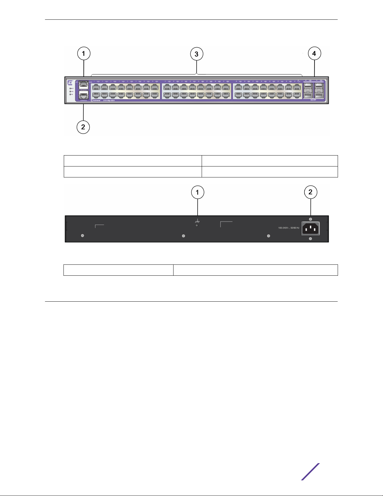
Figure 11: ExtremeSwitching 210-48p-GE4 Switch Front Panel
1 = Ethernet management port 3 = 10/100/1000BASE-T ports
2 = Console port 4 = SFP ports
Figure 12: ExtremeSwitching 210-48p-GE4 Switch Rear Panel
1 = Grounding point
2 = AC power input connector
Overview of the ExtremeSwitching 220 Series Switches
The ExtremeSwitching 220 series switches are 12-, 24, or 48-port switches that provide 10-gigabit
Ethernet connectivity using fixed 10/100/1000BASE-T RJ45 ports and installable SFP+ optical modules.
The ExtremeSwitching 220 series base models are described in the following sections:
ExtremeSwitching 220-12t-10GE2 Switch Ports and Slots on page 17
•
ExtremeSwitching 220-12p-10GE2 Switch Ports and Slots on page 18
•
ExtremeSwitching 220-24t-10GE2 Switch Ports and Slots on page 19
•
ExtremeSwitching 220-24p-10GE2 Switch Ports and Slots on page 20
•
ExtremeSwitching 220-48t-10GE4 Switch Ports and Slots on page 21
•
ExtremeSwitching 220-48p-10GE4 Switch Ports and Slots on page 22
•
Using a serial console port on the front panel of the switch, you can connect a terminal and perform
local management. An Ethernet management port can be used to connect the system to a parallel
management network for administration. Alternatively, you can use an Ethernet cable to connect this
port directly to a laptop to view and locally manage the switch configuration. The Ethernet
management port supports 10/100/1000 Mbps speeds.
ExtremeSwitching 210 and 220 Series Switches: Hardware Installation Guide 16
ExtremeSwitching 210 and 220 Series Switches
The 12-port switches have a small form factor that allows you to install two switches side-by-side in a
standard equipment rack.
Switch cooling is provided by one, two, or three non-replaceable fan modules with side-to-side airflow.
AC power is supplied by a built-in power supply unit that is not user-replaceable.
ExtremeSwitching 220-12t-10GE2 Switch Ports and Slots
The ExtremeSwitching 220-12t-10GE2 switch ports and slots include:
12 10/100/1000BASE-T ports (ports 1–12) that provide 1 GbE connectivity
•
Two dedicated 10 GbE SFP+ ports (ports 13–14)
•
Ethernet management port (10/100BASE-T)
•
Serial console port used to connect a terminal and perform local management
•
LEDs to indicate switch operating conditions
•
For a description of the LEDs and their operation, see ExtremeSwitching 210 and 220 Series Switch
LEDs on page 23.
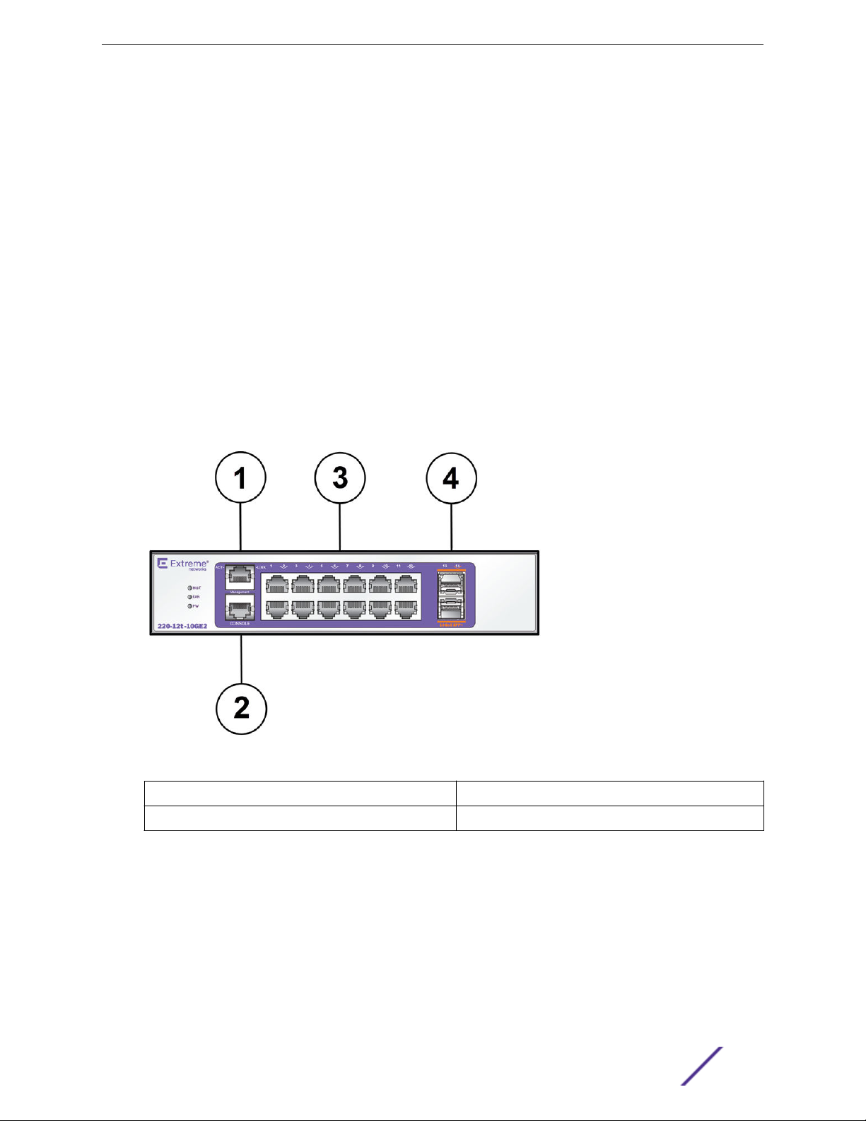
Figure 13: ExtremeSwitching 220-12t-10GE2 Switch Front Panel
1 = Ethernet management port
2 = Console port 4 = 10 GbE SFP+ ports
ExtremeSwitching 210 and 220 Series Switches: Hardware Installation Guide 17
3 = 10/100/1000BASE-T ports
ExtremeSwitching 210 and 220 Series Switches
Figure 14: ExtremeSwitching 220-12t-10GE2 Switch Rear Panel
1 = Grounding point 2 = AC power input connector
ExtremeSwitching 220-12p-10GE2 Switch Ports and Slots
The ExtremeSwitching 220-12p-10GE4 switch ports and slots include:
12 10/100/1000BASE-T PoE+ ports (ports 1–12) that provide 1 GbE connectivity
•
Two dedicated 10 GbE SFP+ ports (ports 13–14)
•
Ethernet management port (10/100BASE-T)
•
Serial console port used to connect a terminal and perform local management
•
LEDs to indicate switch operating conditions
•
For a description of the LEDs and their operation, see ExtremeSwitching 210 and 220 Series Switch
LEDs on page 23.
Figure 15: ExtremeSwitching 220-12p-10GE2 Switch Front Panel
1 = Ethernet management port
ExtremeSwitching 210 and 220 Series Switches: Hardware Installation Guide 18
3 = 10/100/1000BASE-T ports
ExtremeSwitching 210 and 220 Series Switches
2 = Console port 4 = 10 GbE SFP+ ports
Figure 16: ExtremeSwitching 220-12p-10GE2 Switch Rear Panel
1 = Grounding point 2 = AC power input connector
ExtremeSwitching 220-24t-10GE2 Switch Ports and Slots
The ExtremeSwitching 220-24t-10GE2 switch ports and slots include:
24 10/100/1000BASE-T ports (ports 1–24) that provide 1 GbE connectivity
•
Two dedicated 10 GbE SFP+ ports (ports 25–26)
•
Ethernet management port (10/100BASE-T)
•
Serial console port used to connect a terminal and perform local management
•
LEDs to indicate switch operating conditions
•
One rear redundant power supply connector
•
For a description of the LEDs and their operation, see ExtremeSwitching 210 and 220 Series Switch
LEDs on page 23.
Figure 17: ExtremeSwitching 220-24t-10GE2 Switch Front Panel
1 = Ethernet management port
2 = Console port 4 = 10 GbE SFP+ ports
ExtremeSwitching 210 and 220 Series Switches: Hardware Installation Guide 19
3 = 10/100/1000BASE-T ports
ExtremeSwitching 210 and 220 Series Switches
Figure 18: ExtremeSwitching 220-24t-10GE2 Switch Rear Panel
1 = Redundant power input 3 = AC power input connector
2 = Grounding point
ExtremeSwitching 220-24p-10GE2 Switch Ports and Slots
The ExtremeSwitching 220-24p-10GE2 switch ports and slots include:
24 10/100/1000BASE-T PoE+ ports (ports 1–24) that provide 1 GbE connectivity
•
Two dedicated 10 GbE SFP+ ports (ports 25–26)
•
Ethernet management port (10/100BASE-T)
•
Serial console port used to connect a terminal and perform local management
•
LEDs to indicate switch operating conditions
•
One rear redundant power supply connector
•
For a description of the LEDs and their operation, see ExtremeSwitching 210 and 220 Series Switch
LEDs on page 23.
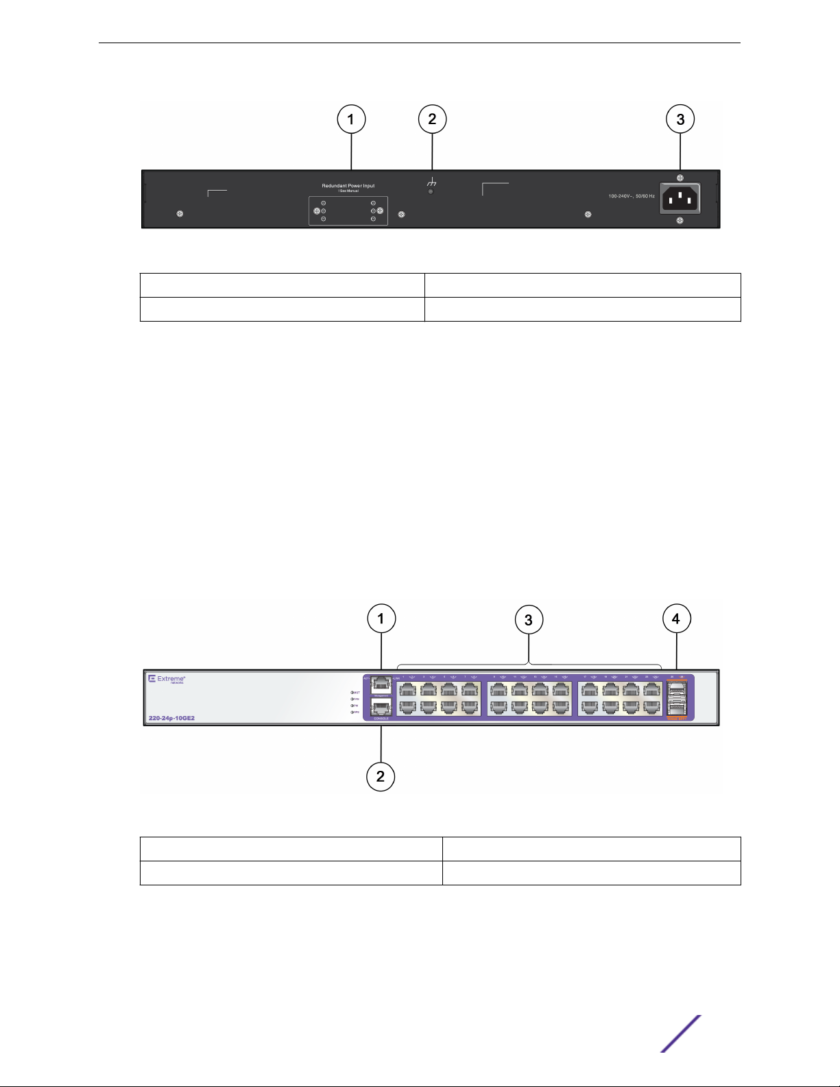
Figure 19: ExtremeSwitching 220-24p-10GE2 Switch Front Panel
1 = Ethernet management port
2 = Console port 4 = 10 GbE SFP+ ports
3 = 10/100/1000BASE-T ports
ExtremeSwitching 210 and 220 Series Switches: Hardware Installation Guide 20

ExtremeSwitching 210 and 220 Series Switches
Figure 20: ExtremeSwitching 220-24p-10GE2 Switch Rear Panel
1 = Redundant power input 3 = AC power input connector
2 = Grounding point
ExtremeSwitching 220-48t-10GE4 Switch Ports and Slots
The ExtremeSwitching 220-48t-10GE4 switch ports and slots include:
48 10/100/1000BASE-T ports (ports 1–48) that provide 1 GbE connectivity
•
Four dedicated 10 GbE SFP+ ports (ports 49–52)
•
Ethernet management port (10/100BASE-T)
•
Serial console port used to connect a terminal and perform local management
•
LEDs to indicate switch operating conditions
•
One rear redundant power supply connector
•
For a description of the LEDs and their operation, see ExtremeSwitching 210 and 220 Series Switch
LEDs on page 23.
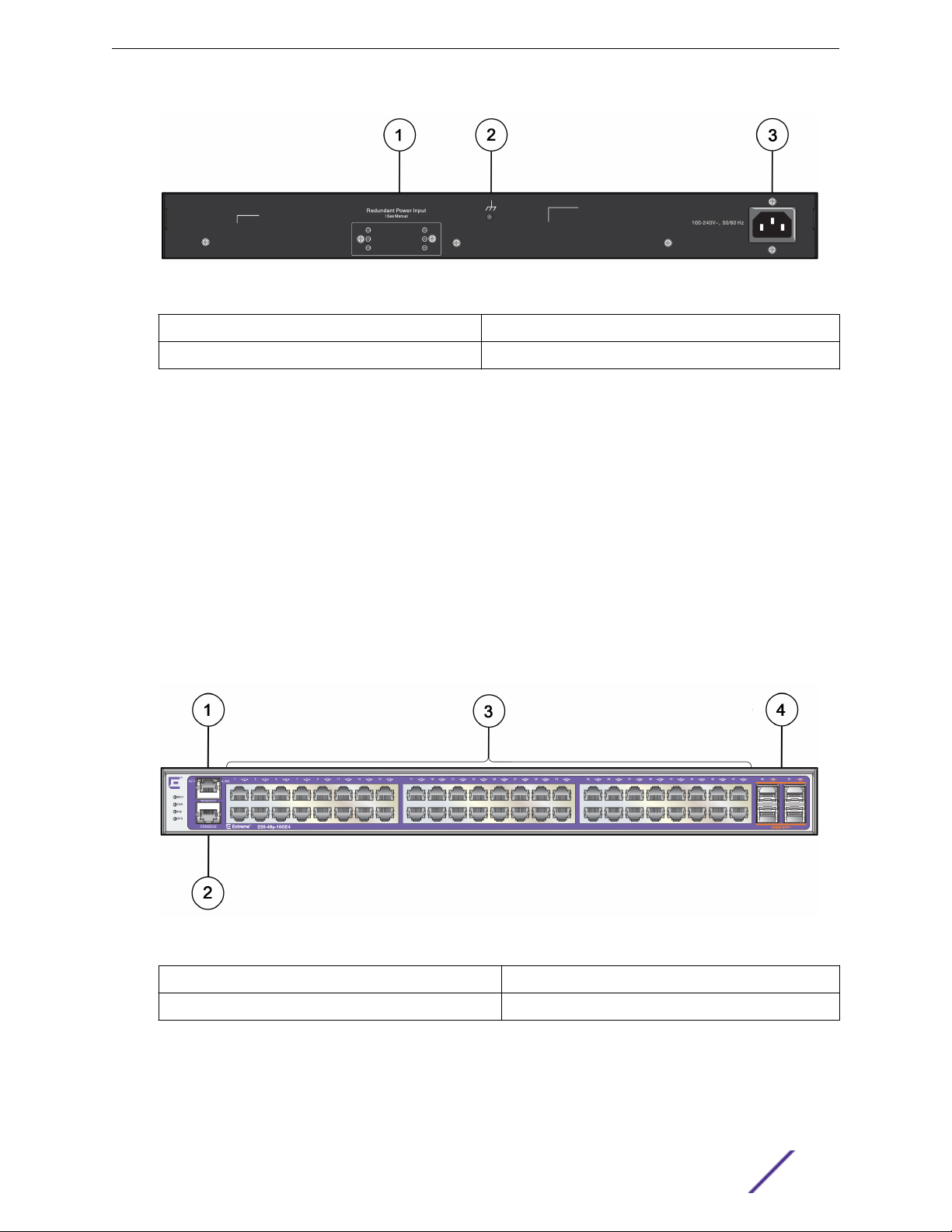
Figure 21: ExtremeSwitching 220-48t-10GE4 Switch Front Panel
1 = Ethernet management port
2 = Console port 4 = 10 GbE SFP+ ports
3 = 10/100/1000BASE-T ports
ExtremeSwitching 210 and 220 Series Switches: Hardware Installation Guide 21
ExtremeSwitching 210 and 220 Series Switches
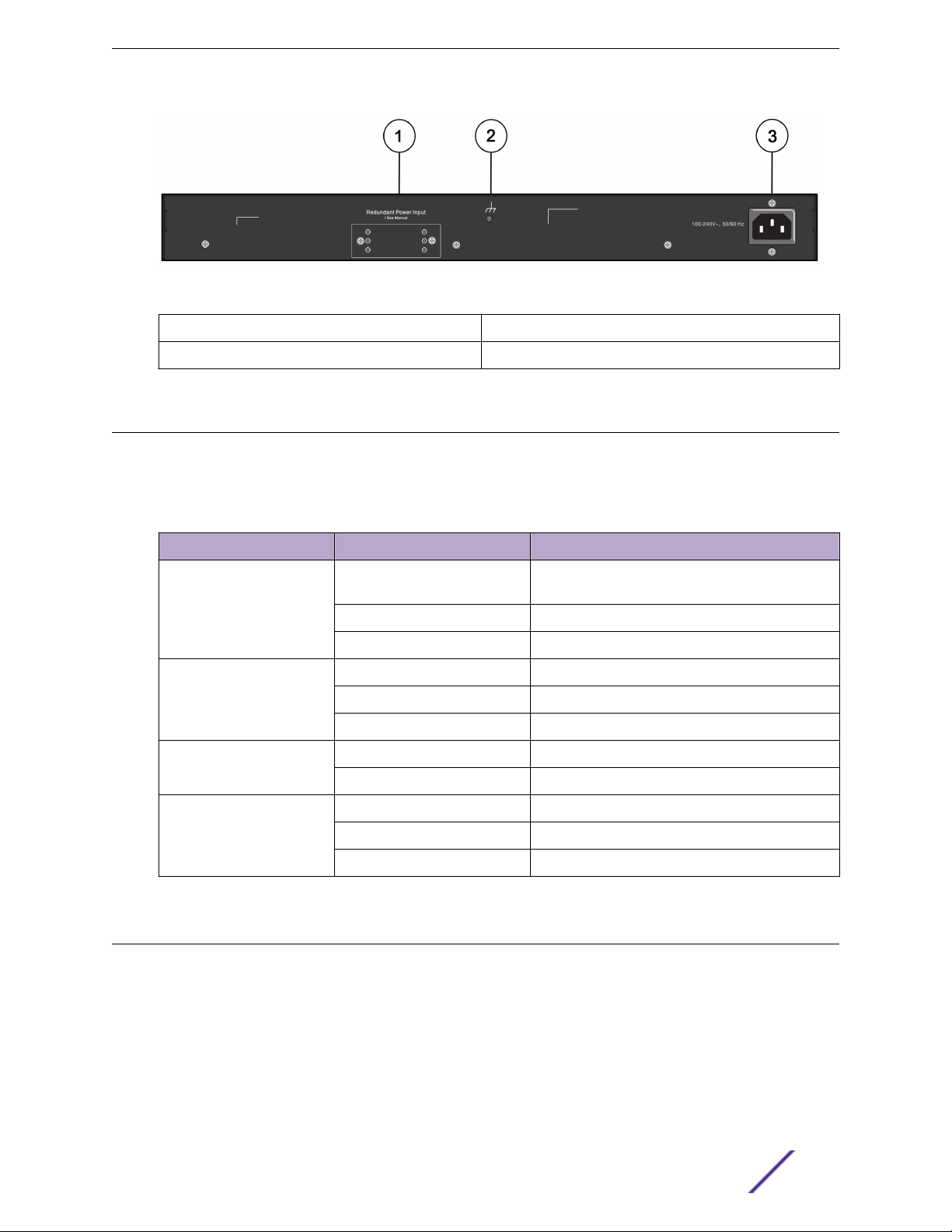
Figure 22: ExtremeSwitching 220-48t-10GE4 Switch Rear Panel
1 = Redundant power input 3 = AC power input connector
2 = Grounding point
ExtremeSwitching 220-48p-10GE4 Switch Ports and Slots
The ExtremeSwitching 220-48p-10GE4 switch ports and slots include:
48 10/100/1000BASE-T PoE+ ports (ports 1–48) that provide 1 GbE connectivity
•
Four dedicated 10 GbE SFP+ ports (ports 49–52)
•
Ethernet management port (10/100BASE-T)
•
Serial console port used to connect a terminal and perform local management
•
LEDs to indicate switch operating conditions
•
One rear redundant power supply connector
•
For a description of the LEDs and their operation, see ExtremeSwitching 210 and 220 Series Switch
LEDs on page 23.
Figure 23: ExtremeSwitching 220-48p-10GE4 Switch Front Panel
1 = Ethernet management port
2 = Console port 4 = 10 GbE SFP+ ports
3 = 10/100/1000BASE-T ports
ExtremeSwitching 210 and 220 Series Switches: Hardware Installation Guide 22
ExtremeSwitching 210 and 220 Series Switches
Figure 24: ExtremeSwitching 220-48p-10GE4 Switch Rear Panel
1 = Redundant power input 3 = AC power input connector
2 = Grounding point
ExtremeSwitching 210 and 220 Series Switch LEDs
The following table describes the meanings of the LEDs on the ExtremeSwitching 210 and 220 series
switches.
Table 3: Front Panel LEDs
Label or Type Color/State Meaning
MGT (Management) Slowly blinking green Power-on self test (POST) has finished. This is
normal operation.
Blinking green POST in progress.
O No power.
FAN Steady green Normal operation.
Blinking amber Failure.
O No power.
PW
(Power Supply)
RPS
(Remote Power Supply)
220 Series 24- and 48-port
models only
Steady green Normal operation.
O No power.
Steady green RPS working properly.
Blinking amber RPS failure.
O No RPS.
Pluggable Interfaces for ExtremeSwitching Switches
Some 210 and 220 series switches include ports that are compatible with a variety of optical modules,
including SFP and SFP+ modules. Extreme Networks optical modules are tested to work in all
supported Extreme Networks devices. We recommend that all customers use Extreme Networks optical
modules in their Extreme Networks devices.
Extreme Networks assumes no liability for third-party optical modules. Although Extreme Networks
does not block third-party optical modules, we cannot ensure that all third-party optical modules
ExtremeSwitching 210 and 220 Series Switches: Hardware Installation Guide 23

ExtremeSwitching 210 and 220 Series Switches
operate properly in all Extreme Networks devices. The customer assumes all risks associated with using
third-party optical modules in Extreme Networks devices.
For more information, refer to the Extreme Networks Pluggable Transceivers Installation Guide.
ExtremeSwitching 210 and 220 Series Switches: Hardware Installation Guide 24

2 External Power Supplies
RPS-150XT Redundant Power Supply
RPS-500p Redundant Power Supply
Installing External Power Supplies
Some ExtremeSwitching 220 switch models can use an external power supply to help ensure
redundancy. The following external power supplies are available:
RPS-150XT Redundant Power Supply on page 25
•
RPS-500p Redundant Power Supply on page 27
•
External power supplies are supported as follows:
Table 4: External Power Supplies Supported for 220 Series Switches
Switch Model RPS-150XT RPS-500p
220-24t-10GE2 yes
220-24p-10GE2 yes
220-48t-10GE4 yes
220-48p-10GE4 yes
For instructions on attaching your switch to an external power supply, see Installing External Power
Supplies on page 28.
RPS-150XT Redundant Power Supply
The RPS-150XT provides backup power to Extreme Networks stackable switches. If for some reason the
switch loses power from its internal power supply, the RPS-150XT can provide up to 150 W maximum
operating power to support switch operation.
The power supply ships with the following:
RPS cable
•
Four rubber feet (for flat surface installation)
•
The RPS-150XT is compatible with the following Extreme Networks switches:
ExtremeSwitching X440-G2-24t-10GE4 switch
•
ExtremeSwitching X440-G2-24x-10GE4 switch
•
ExtremeSwitching X440-G2-48t-10GE4 switch
•
ExtremeSwitching X440-G2-24t-10GE4-DC switch
•
ExtremeSwitching X440-G2-48t-10GE4-DC switch
•
ExtremeSwitching X440-G2-12t8fx-GE4 switch
•
ExtremeSwitching X440-G2-24fx-GE4 switch
•
ExtremeSwitching 210 and 220 Series Switches: Hardware Installation Guide 25
 Loading...