

Extreme Networks 2000, 2024F-4X, 2024C, 2024F, 2048C Hardware Installation Manual
...
HARDWARE INSTALLATION GUIDE
ExtremeSwitching CES 2000 Series and
ExtremeRouting CER 2000 Series
Hardware Installation Guide
9035631-01
November 2018

Copyright © 2018 Extreme Networks, Inc. All Rights Reserved.
Legal Notice
Extreme Networks, Inc. reserves the right to make changes in specications and other information contained in this document and its
website without prior notice. The reader should in all cases consult representatives of Extreme Networks to determine whether any such
changes have been made.
The hardware, rmware, software or any specications described or referred to in this document are subject to change without notice.
Trademarks
Extreme Networks and the Extreme Networks logo are trademarks or registered trademarks of Extreme Networks, Inc. in the United
States and/or other countries.
All other names (including any product names) mentioned in this document are the property of their respective owners and may be
trademarks or registered trademarks of their respective companies/owners.
For additional information on Extreme Networks trademarks, please see: www.extremenetworks.com/company/legal/trademarks
Software Licensing
Some software
declarations can be found at: www.extremenetworks.com/support/policies/software-licensing
les have been licensed under certain open source or third-party licenses. End-user license agreements and open source
Support
For product support, phone the Global Technical Assistance Center (GTAC) at 1-800-998-2408 (toll-free in U.S. and Canada) or
+1-408-579-2826. For the support phone number in other countries, visit: http://www.extremenetworks.com/support/contact/
For product documentation online, visit: https://www.extremenetworks.com/documentation/
2 9035631-01
ExtremeSwitching CES 2000 Series and ExtremeRouting CER 2000 Series Hardware Installation Guide

Contents
Preface...................................................................................................................................................................................................................................7
Conventions..................................................................................................................................................................................................................................................7
Notes, cautions, and warnings.....................................................................................................................................................................................................7
Text formatting conventions.........................................................................................................................................................................................................7
Command syntax conventions....................................................................................................................................................................................................8
Documentation and Training................................................................................................................................................................................................................. 8
Open Source Declarations............................................................................................................................................................................................................8
Training..................................................................................................................................................................................................................................................8
Getting Help................................................................................................................................................................................................................................................. 9
Subscribing to Service Notications.........................................................................................................................................................................................9
Providing Feedback to Us...................................................................................................................................................................................................................... 9
About This Document..................................................................................................................................................................................................... 11
Audience.....................................................................................................................................................................................................................................................11
Supported hardware and software................................................................................................................................................................................................... 11
How command information is presented in this guide............................................................................................................................................................12
Notice to the reader................................................................................................................................................................................................................................12
What’s new in this document............................................................................................................................................................................................................. 12
Product Overview.............................................................................................................................................................................................................13
Introduction................................................................................................................................................................................................................................................13
Product overview.....................................................................................................................................................................................................................................19
Software features.....................................................................................................................................................................................................................................20
Upgrade applications.............................................................................................................................................................................................................................20
Hardware features................................................................................................................................................................................................................................... 21
CES 2000 Series 2024C-4X.................................................................................................................................................................................................21
CES 2000 Series 2024F-4X................................................................................................................................................................................................. 21
CES 2000 Series 2024C......................................................................................................................................................................................................... 22
CES 2000 Series 2024F..........................................................................................................................................................................................................22
CES 2000 Series 2048C......................................................................................................................................................................................................... 22
CES 2000 Series 2048CX...................................................................................................................................................................................................... 23
CES 2000 Series 2048F..........................................................................................................................................................................................................23
CES 2000 Series 2048FX.......................................................................................................................................................................................................24
CER 2000 Series 2024C.........................................................................................................................................................................................................24
CER 2000 Series 2024F......................................................................................................................................................................................................... 25
CER 2000 Series 2048C.........................................................................................................................................................................................................25
CER 2000 Series 2048CX......................................................................................................................................................................................................26
CER 2000 Series 2048F......................................................................................................................................................................................................... 26
CER 2000 Series 2048FX...................................................................................................................................................................................................... 27
Control features.............................................................................................................................................................................................................................. 27
Network interfaces.........................................................................................................................................................................................................................31
Power supplies................................................................................................................................................................................................................................32
Cooling system and fans............................................................................................................................................................................................................33
Connecting to a Network Device ..................................................................................................................................................................................35
Password assignment...........................................................................................................................................................................................................................35
IP address conguration...................................................................................................................................................................................................................... 36
Support of sub-net masks.........................................................................................................................................................................................................36
ExtremeSwitching CES 2000 Series and ExtremeRouting CER 2000 Series Hardware Installation Guide
9035631-01 3

Assigning an IP address to a management interface.....................................................................................................................................................37
Assigning an IP address to an interface, virtual interface, or loopback...................................................................................................................37
Enabling and disabling the interfaces....................................................................................................................................................................................38
Management port function overview..............................................................................................................................................................................................39
Device connection..................................................................................................................................................................................................................................39
Installation..........................................................................................................................................................................................................................41
System unpacking..................................................................................................................................................................................................................................41
Package contents...........................................................................................................................................................................................................................41
General requirements...................................................................................................................................................................................................................41
Summary of installation tasks............................................................................................................................................................................................................42
Installation precautions......................................................................................................................................................................................................................... 42
Lifting precautions.........................................................................................................................................................................................................................43
Power precautions.........................................................................................................................................................................................................................43
Installation site preparation..................................................................................................................................................................................................................44
Cabling infrastructure...................................................................................................................................................................................................................44
Installation location........................................................................................................................................................................................................................45
Redundant power supply installation..............................................................................................................................................................................................45
Installing an AC power supply..................................................................................................................................................................................................45
Installing a DC power supply.................................................................................................................................................................................................... 48
Device installation................................................................................................................................................................................................................................... 51
Installing the device on a desktop...........................................................................................................................................................................................51
Installing the device in a rack.....................................................................................................................................................................................................51
System power...........................................................................................................................................................................................................................................56
Powering on the system............................................................................................................................................................................................................. 57
Operation verication............................................................................................................................................................................................................................ 57
Verifying proper operation......................................................................................................................................................................................................... 57
Observing the power status LEDs......................................................................................................................................................................................... 58
PC or terminal attachment.................................................................................................................................................................................................................. 59
Attaching a PC or terminal.........................................................................................................................................................................................................59
Device Management Applications Familiarization.................................................................................................................................................... 61
Management application overview..................................................................................................................................................................................................61
CLI Functionality......................................................................................................................................................................................................................................61
Online help....................................................................................................................................................................................................................................... 61
Command completion.................................................................................................................................................................................................................62
Scroll control....................................................................................................................................................................................................................................62
Line editing commands.............................................................................................................................................................................................................. 62
Searching and ltering output from CLI commands......................................................................................................................................................63
Hardware Specications.................................................................................................................................................................................................69
Power specications..............................................................................................................................................................................................................................69
Physical dimensions..............................................................................................................................................................................................................................70
Operating environment ........................................................................................................................................................................................................................71
Storage environment ............................................................................................................................................................................................................................71
Cooling........................................................................................................................................................................................................................................................ 71
Safety agency approvals...................................................................................................................................................................................................................... 72
Electromagnetic approvals.................................................................................................................................................................................................................. 72
Port specications.................................................................................................................................................................................................................................. 72
Console port pin assignments................................................................................................................................................................................................. 73
Management port pin assignments.......................................................................................................................................................................................73
4 9035631-01
ExtremeSwitching CES 2000 Series and ExtremeRouting CER 2000 Series Hardware Installation Guide

Hardware Maintenance....................................................................................................................................................................................................75
Hardware maintenance schedule..................................................................................................................................................................................................... 75
Power supply replacement..................................................................................................................................................................................................................75
Installation precautions and warnings....................................................................................................................................................................................75
Determining which power supply failed............................................................................................................................................................................... 76
AC power supply ...........................................................................................................................................................................................................................76
Power supplies for the devices................................................................................................................................................................................................ 77
Verifying proper operation......................................................................................................................................................................................................... 85
10-Gigabit Ethernet module installation or replacement.......................................................................................................................................................86
Removing a 2 x10-Gigabit Ethernet module....................................................................................................................................................................86
Installing a 2 x10-Gigabit Ethernet Module.......................................................................................................................................................................87
Replacing the fan tray............................................................................................................................................................................................................................87
Copper or Fiber optic module replacement.................................................................................................................................................................................88
Removing a Copper or ber optic module..........................................................................................................................................................................88
Installing a new Copper or ber optic module...................................................................................................................................................................89
Cabling a ber optic module.....................................................................................................................................................................................................90
Tunable 10 GbE DWDM SFP+............................................................................................................................................................................................... 90
Fiber optic connector cleaning..........................................................................................................................................................................................................91
Regulatory Statements....................................................................................................................................................................................................93
BSMI statement (Taiwan).....................................................................................................................................................................................................................93
Canadian requirements.........................................................................................................................................................................................................................93
China CC statement...............................................................................................................................................................................................................................94
Europe and Australia (CISPR 22 Class A Warning)..................................................................................................................................................................94
FCC warning (US only)..........................................................................................................................................................................................................................95
Germany statement................................................................................................................................................................................................................................95
KCC statement (Republic of Korea)................................................................................................................................................................................................. 95
VCCI statement........................................................................................................................................................................................................................................95
Japan power cord ...................................................................................................................................................................................................................................96
EMC, safety, and environmental regulatory compliance information................................................................................................................................96
Regulatory compliance (EMC)..................................................................................................................................................................................................96
Regulatory compliance (safety)................................................................................................................................................................................................ 96
Regulatory compliance (environmental)............................................................................................................................................................................... 96
Caution and Danger Notices..........................................................................................................................................................................................99
Cautions......................................................................................................................................................................................................................................................99
General cautions.............................................................................................................................................................................................................................99
Electrical cautions.......................................................................................................................................................................................................................100
Cautions related to equipment weight...............................................................................................................................................................................104
Danger Notices.....................................................................................................................................................................................................................................104
General dangers..........................................................................................................................................................................................................................104
Electrical dangers........................................................................................................................................................................................................................105
Dangers related to equipment weight................................................................................................................................................................................107
Laser dangers.............................................................................................................................................................................................................................. 108
ExtremeSwitching CES 2000 Series and ExtremeRouting CER 2000 Series Hardware Installation Guide
9035631-01 5

6 9035631-01
ExtremeSwitching CES 2000 Series and ExtremeRouting CER 2000 Series Hardware Installation Guide

Preface
• Conventions............................................................................................................................................................................................................7
• Documentation and Training............................................................................................................................................................................8
• Getting Help............................................................................................................................................................................................................9
• Providing Feedback to Us.................................................................................................................................................................................9
This section discusses the conventions used in this guide, ways to provide feedback, additional help, and other Extreme Networks
publications.
Conventions
This section discusses the conventions used in this guide.
Notes, cautions, and warnings
Notes, cautions, and warning statements may be used in this document. They are listed in the order of increasing severity of potential
hazards.
NOTE
A Note provides a tip, guidance, or advice, emphasizes important information, or provides a reference to related information.
ATTENTION
An Attention statement indicates a stronger note, for example, to alert you when trac might be interrupted or the device might
reboot.
®
CAUTION
A Caution statement alerts you to situations that can be potentially hazardous to you or cause damage to hardware,
rmware, software, or data.
DANGER
A Danger statement indicates conditions or situations that can be potentially lethal or extremely hazardous to you. Safety
labels are also attached directly to products to warn of these conditions or situations.
Text formatting conventions
Text formatting conventions such as boldface, italic, or Courier font may be used to highlight specic words or phrases.
Format Description
bold text Identies command names.
Identies keywords and operands.
Identies the names of GUI elements.
Identies text to enter in the GUI.
italic text Identies emphasis.
Identies variables.
Identies document titles.
ExtremeSwitching CES 2000 Series and ExtremeRouting CER 2000 Series Hardware Installation Guide
9035631-01 7

Documentation and Training
Format Description
Courier font
Identies CLI output.
Identies command syntax examples.
Command syntax conventions
Bold and italic text identify command syntax components. Delimiters and operators
relationships.
Convention Description
bold text Identies command names, keywords, and command options.
italic text Identies a variable.
[ ] Syntax components displayed within square brackets are optional.
Default responses to system prompts are enclosed in square brackets.
{ x | y | z } A choice of required parameters is enclosed in curly brackets separated by vertical bars. You must select
one of the options.
x | y A vertical bar separates mutually exclusive elements.
< > Nonprinting characters, for example, passwords, are enclosed in angle brackets.
... Repeat the previous element, for example, member[member...].
\ Indicates a “soft” line break in command examples. If a backslash separates two lines of a command
input, enter the entire command at the prompt without the backslash.
dene groupings of parameters and their logical
Documentation and Training
To nd Extreme Networks product guides, visit our documentation pages at:
Current Product Documentation www.extremenetworks.com/documentation/
Archived Documentation (for earlier versions and
legacy products)
Release Notes www.extremenetworks.com/support/release-notes
Hardware/Software Compatibility Matrices https://www.extremenetworks.com/support/compatibility-matrices/
White papers, data sheets, case studies, and other
product resources
www.extremenetworks.com/support/documentation-archives/
https://www.extremenetworks.com/resources/
Open Source Declarations
Some software
support/policies/open-source-declaration/.
les have been licensed under certain open source licenses. More information is available at: www.extremenetworks.com/
Training
Extreme Networks oers product training courses, both online and in person, as well as specialized certications. For more information,
visit www.extremenetworks.com/education/.
8 9035631-01
ExtremeSwitching CES 2000 Series and ExtremeRouting CER 2000 Series Hardware Installation Guide

Providing Feedback to Us
Getting Help
If you require assistance, contact Extreme Networks using one of the following methods:
Extreme Portal Search the GTAC (Global Technical Assistance Center) knowledge base, manage support cases and service
contracts, download software, and obtain product licensing, training, and certications.
The Hub A forum for Extreme Networks customers to connect with one another, answer questions, and share ideas and
feedback. This community is monitored by Extreme Networks employees, but is not intended to replace specic
guidance from GTAC.
Call GTAC For immediate support: 1-800-998-2408 (toll-free in U.S. and Canada) or +1 408-579-2826. For the support
phone number in your country, visit: www.extremenetworks.com/support/contact
Before contacting Extreme Networks for technical support, have the following information ready:
• Your Extreme Networks service contract number and/or serial numbers for all involved Extreme Networks products
• A description of the failure
• A description of any action(s) already taken to resolve the problem
• A description of your network environment (such as layout, cable type, other relevant environmental information)
• Network load at the time of trouble (if known)
• The device history (for example, if you have returned the device before, or if this is a recurring problem)
• Any related RMA (Return Material Authorization) numbers
Subscribing to Service
You can subscribe to email notications for product and software release announcements, Vulnerability Notices, and Service
Notications.
1. Go to www.extremenetworks.com/support/service-notication-form.
2. Complete the form with your information (all elds are required).
3. Select the products for which you would like to receive notications.
NOTE
You can modify your product selections or unsubscribe at any time.
4. Click Submit.
Notications
Providing Feedback to Us
Quality is our
document. We are always striving to improve our documentation and help you work better, so we want to hear from you! We welcome all
feedback but especially want to know about:
• Content errors or confusing or conicting information.
• Ideas for improvements to our documentation so you can nd the information you need faster.
• Broken links or usability issues.
rst concern at Extreme Networks, and we have made every eort to ensure the accuracy and completeness of this
If you would like to provide feedback to the Extreme Networks Information Development team, you can do so in two ways:
• Use our short online feedback form at https://www.extremenetworks.com/documentation-feedback/.
ExtremeSwitching CES 2000 Series and ExtremeRouting CER 2000 Series Hardware Installation Guide
9035631-01 9

Providing Feedback to Us
• Email us at documentation@extremenetworks.com.
Please provide the publication title, part number, and as much detail as possible, including the topic heading and page number if
applicable, as well as your suggestions for improvement.
10 9035631-01
ExtremeSwitching CES 2000 Series and ExtremeRouting CER 2000 Series Hardware Installation Guide

About This Document
• Audience................................................................................................................................................................................................................11
• Supported hardware and software..............................................................................................................................................................11
• How command information is presented in this guide...................................................................................................................... 12
• Notice to the reader..........................................................................................................................................................................................12
• What’s new in this document........................................................................................................................................................................12
Audience
This document is designed for system administrators with a working knowledge of Layer 2 and Layer 3 switching and routing.
If you are using an Extreme Networks device, you should be familiar with the following protocols if applicable to your network - IP, RIP,
OSPF, BGP, ISIS, IGMP, PIM, MPLS, and VRRP.
Supported hardware and software
End of support for ExtremeSwitching CES 2000 Series devices
Beginning with NetIron OS 6.3.00a and later, the ExtremeSwitching CES 2000 Series devices are not supported. Refer to the End of
Sale and End of Support page under https://www.extremenetworks.com/support/end-of-sale-and-end-of-support-products/ for
additional information .
The following hardware platforms are supported by the release of this guide:
TABLE 1 Supported devices
ExtremeRouting CER 2000 Series Supported
ExtremeRouting CER 2024C-4X-RT Yes
ExtremeRouting CER 2024F-4X-RT Yes
ExtremeRouting CER 2024C Yes
ExtremeRouting CER-RT 2024C Yes
ExtremeRouting CER 2024F Yes
ExtremeRouting CER-RT 2024F Yes
ExtremeRouting CER 2048C Yes
ExtremeRouting CER-RT 2048C Yes
ExtremeRouting CER 2048CX Yes
ExtremeRouting CER-RT 2048CX Yes
ExtremeRouting CER 2048F Yes
ExtremeRouting CER-RT 2048F Yes
ExtremeRouting CER 2048FX Yes
ExtremeRouting CER-RT 2048FX Yes
ExtremeSwitching CES 2000 Series and ExtremeRouting CER 2000 Series Hardware Installation Guide
9035631-01 11

How command information is presented in this guide
How command information is presented in this guide
Starting with Extreme NetIron 5.6.00, command syntax and parameter descriptions are removed from commands that are referenced in
conguration tasks. To nd the full description of a specic command, including all required and optional keywords and variables, refer to
the Extreme NetIron Command Reference for your software release.
Notice to the reader
This document may contain references to the trademarks of the following corporations. These trademarks are the properties of their
respective companies and corporations.
These references are made for informational purposes only.
Corporation Referenced Trademarks and Products
Microsoft Corporation Internet Explorer
Mozilla Corporation Mozilla Firefox
Oracle Corporation Java Runtime Environment
What’s new in this document
NOTE
The NetIron 6.3.00 release (the image les and the documentation) is no longer available from the Extreme Portal. New
software features introduced in release 6.3.00 are included in release 6.3.00a.
On October 30, 2017, Extreme Networks, Inc. acquired the data center networking business from Brocade Communications Systems,
Inc. This document has been updated to remove or replace references to Brocade Communications, Inc. with Extreme Networks., Inc., as
appropriate.
For the complete list of supported features and the summary of enhancements and conguration notes for this release, refer to the
Extreme NetIron OS Release Notes.
12 9035631-01
ExtremeSwitching CES 2000 Series and ExtremeRouting CER 2000 Series Hardware Installation Guide

Product Overview
• Introduction.......................................................................................................................................................................................................... 13
• Product overview...............................................................................................................................................................................................19
• Software features............................................................................................................................................................................................... 20
• Upgrade applications....................................................................................................................................................................................... 20
• Hardware features..............................................................................................................................................................................................21
Introduction
Network planners today have to expand and extend the range of services oered further into the edge of the network. This requires
extending the intelligence and high-touch processing capabilities to the network edge-- whether in a metro network, a campus network
or in a data center. The challenge at the edge of the network is compounded by the need to exibly dene and easily manage customer
services in an intuitive manner. Further, of many rollouts. Whether deployed from a central oce or from remote huts, space is an
important constraint for such providers.
In order to meet these challenges, the ExtremeSwitching CES 2000 Series and ExtremeRouting CER 2000 Series were purpose-built
to oer exible, secure and advanced processing capabilities in a compact form factor. The CES Series 2000 and CER 2000 Series are
compact 1 RU, multi-service edge or aggregation devices with a powerful set of capabilities chosen to combine performance with rich
functionality at the edge of the network. The CES 2000 Series and CER 2000 Series devices oer network planners a rich set of highperformance IPv4, Classic Layer 2, Provider Bridge (PB) and Provider Backbone Bridge (PBB) functionalities in the same device. With
these capabilities, a diverse set of applications ranging from metro edge networks, ISPs, data centers, large enterprises, government
networks, and education or research can be addressed with the CES 2000 Series and CER 2000 Series devices.
This guide includes procedures for installing the hardware and conguring essential, basic parameters such as permanent passwords and
IP addresses. The basic software conguration procedures show how to perform tasks using the CLI. This guide also includes
instructions for managing and maintaining the ExtremeSwitching CES 2000 Series and ExtremeRouting CER 2000 Series hardware.
There are eight avors to the NetIron Carrier Ethernet Switch (CES) 2000 Series:
• CES 2000 Series 2024C-4X -- accommodates 24-port 10/100/1000 RJ45 model with 4 combination 100/1000 Hybrid
Fiber (HF) ports and 4x10G SFP+ uplinks
• CES 2000 Series 2024F-4X -- accommodates 24-port 100/1000 Hybrid Fiber (HF) model with 4 combination
10/100/1000 RJ45 ports and 4x10G SFP+ uplinks
• CES 2000 Series 2024C -- accommodates 24-port 10/100/1000 RJ45 model with 4 combination 100/1000 Hybrid
Fiber (HF) ports and an optional eld upgradeable 2x10G uplink slot
• CES 2000 Series 2024F -- accommodates 24-port 100/1000 Hybrid Fiber (HF) model with 4 combination 10/100/1000
RJ45 ports and an optional eld upgradeable 2x10G XFP uplink slot
• CES 2000 Series 2048C -- accommodates 48-port 10/100/1000 RJ45 model with 4 combination 100/1000 Hybrid
Fiber (HF) ports
• CES 2000 Series 2048CX -- accommodates 48-port 10/100/1000 RJ45 model with 2x10G XFP uplink ports
• CES 2000 Series 2048F -- accommodates 48-port 100/1000 Hybrid Fiber (HF) model
• CES 2000 Series 2048FX -- accommodates 48-port 100/1000 Hybrid Fiber (HF) model with 2x10G XFP uplink ports
ExtremeSwitching CES 2000 Series and ExtremeRouting CER 2000 Series Hardware Installation Guide
9035631-01 13
Introduction
FIGURE 1 CES 2000 Series 2024C-4X
FIGURE 2 CES 2000 Series 2024F-4X
FIGURE 3 CES 2000 Series 2024C
14 9035631-01
ExtremeSwitching CES 2000 Series and ExtremeRouting CER 2000 Series Hardware Installation Guide
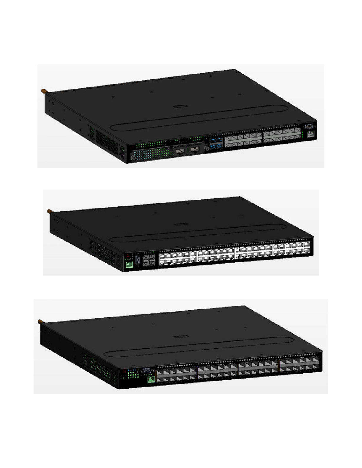
FIGURE 4 CES 2000 Series 2024F
FIGURE 5 CES 2000 Series 2048C
Introduction
FIGURE 6 CES 2000 Series 2048F
ExtremeSwitching CES 2000 Series and ExtremeRouting CER 2000 Series Hardware Installation Guide
9035631-01 15

Introduction
FIGURE 7 CES 2000 Series 2048CX
FIGURE 8 CES 2000 Series 2048FX
There are also fourteen models in the ExtremeRouting (CER and CER-RT) 2000 Series:
• CER 2000 Series 2024C-4X -RT -- accommodates 24-port 10/100/1000 RJ45 model with 4 combination 100/1000
Hybrid Fiber (HF) ports and 4x10G SFP+ uplinks. This device has the ability to simultaneously store up to 1.5 million IPv4
routes and up to 256,000 IPv6 routes
• CER 2000 Series 2024F-4X-RT -- accommodates 24-port 100/1000 Hybrid Fiber (HF) model with 4 combination
10/100/1000 RJ45 ports and 4x10G SFP+ uplinks. This device has the ability to simultaneously store up to 1.5 million IPv4
routes and up to 256,000 IPv6 routes
• CER 2000 Series 2024C -- accommodates 24-port 10/100/1000 Copper RJ45 model with 4 combination 100/1000
Hybrid Fiber (HF) ports and an optional eld upgradeable 2x10G uplink slot
• CER 2000 Series- RT 2024C -- accommodates 24-port 10/100/1000 Copper RJ45 model with 4 combination
100/1000 Hybrid Fiber (HF) ports and an optional eld upgradeable 2x10G uplink slot. This device has the ability to
simultaneously store up to 1.5 million IPv4 routes and up to 256,000 IPv6 routes
• CER 2000 Series 2024F -- accommodates 24-port 100/1000 Hybrid Fiber (HF) model with 4 combination 10/100/1000
RJ45 ports and an optional eld upgradeable 2x10G XFP uplink slot
• CER 2000 Series- RT 2024F -- accommodates 24-port 100/1000 Hybrid Fiber (HF) model with 4 combination
10/100/1000 RJ45 ports and an optional eld upgradeable 2x10G XFP uplink slot. This device has the ability to
simultaneously store up to 1.5 million IPv4 routes and up to 256,000 IPv6 routes
• CER 2000 Series 2048C -- accommodates 48-port 10/100/1000 Copper RJ45 model with 4 combination 100/1000
Hybrid Fiber (HF) ports
16 9035631-01
ExtremeSwitching CES 2000 Series and ExtremeRouting CER 2000 Series Hardware Installation Guide
• CER 2000 Series- RT 2048C -- accommodates 48-port 10/100/1000 Copper RJ45 model with 4 combination
100/1000 Hybrid Fiber (HF) ports. This device has the ability to simultaneously store up to 1.5 million IPv4 routes and up to
256,000 IPv6 routes
• CER 2000 Series 2048F -- accommodates 48-port 100/1000 Hybrid Fiber (HF) model
• CER 2000 Series- RT 2048F -- accommodates 48-port 100/1000 Hybrid Fiber (HF) model This device has the ability to
simultaneously store up to 1.5 million IPv4 routes and up to 256,000 IPv6 routes
• CER 2000 Series 2048CX -- accommodates 48-port 10/100/1000 RJ45 model with 2x10G XFP uplink ports
• CER 2000 Series- RT2048CX -- accommodates 48-port 10/100/1000 RJ45 model with 2x10G XFP uplink ports. This
device has the ability to simultaneously store up to 1.5 million IPv4 routes and up to 256,000 IPv6 routes
• CER 2000 Series 2048FX -- accommodates 48-port 100/1000 Hybrid Fiber (HF) model with 2x10G XFP uplink ports
• CER 2000 Series- RT 2048FX -- accommodates 48-port 100/1000 Hybrid Fiber (HF) model with 2x10G XFP uplink
ports. This device has the ability to simultaneously store up to 1.5 million IPv4 routes and up to 256,000 IPv6 routes
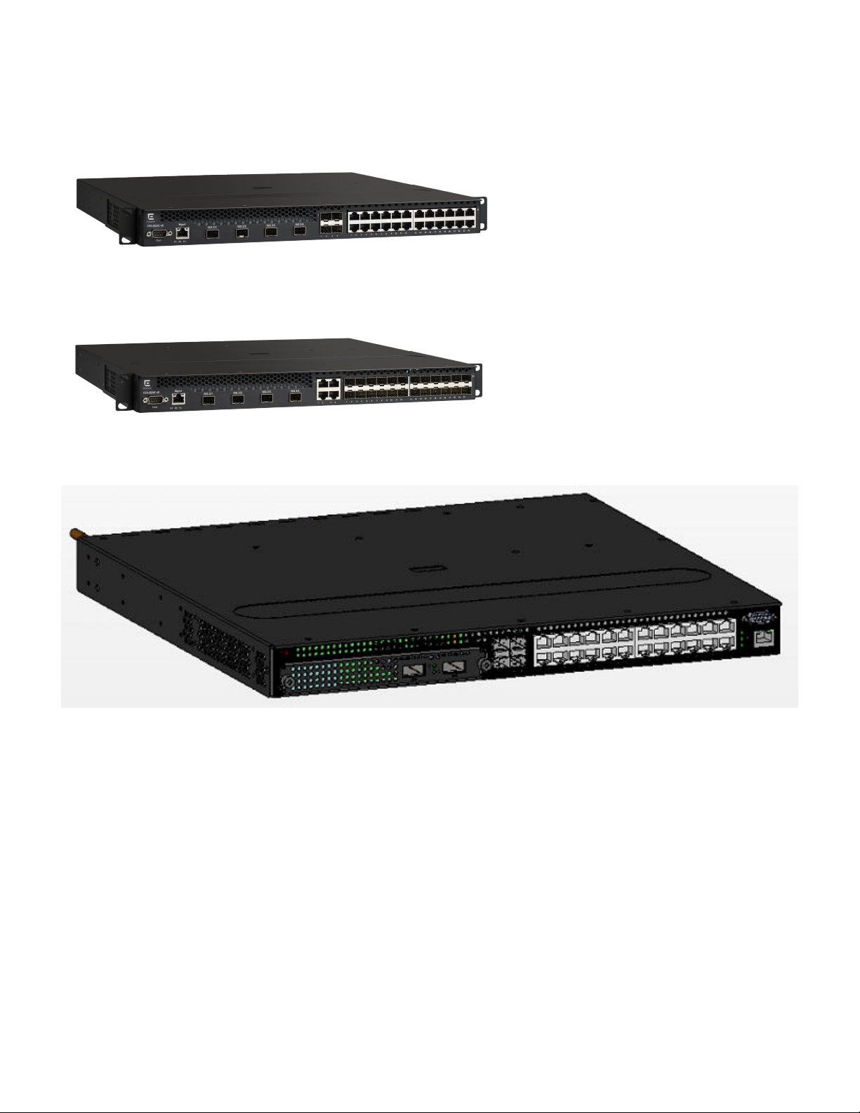
FIGURE 9 CER 2000 Series 2024C-4X-RT
Introduction
FIGURE 10 CER 2000 Series 2024F-4X-RT
FIGURE 11 CER 2000 Series 2024C
ExtremeSwitching CES 2000 Series and ExtremeRouting CER 2000 Series Hardware Installation Guide
9035631-01 17

Introduction
FIGURE 12 CER 2000 Series 2024F
FIGURE 13 CER 2000 Series 2048C
FIGURE 14 CER 2000 Series 2048F
18 9035631-01
ExtremeSwitching CES 2000 Series and ExtremeRouting CER 2000 Series Hardware Installation Guide

FIGURE 15 CER 2000 Series 2048CX
FIGURE 16 CER 2000 Series 2048FX
Product overview
Product overview
The CES 2000 Series is a compact 1 RU, multi-service edge or aggregation switch with a powerful set of capabilities that combine
performance with rich functionality at the network edge. The CES 2000 Series switch oers network planners a broad set of high
performance IPv4, Classic Layer 2, Provider Bridge (PB) and Provider Backbone Bridge (PBB) functionalities in the same device. With
these capabilities, the CES 2000 Series addresses a diverse set of applications in metro edge networks, ISP networks, mobile backhaul
networks, data centers, large enterprises, government networks and education or research.
FIGURE 17 CES 2000 Series switch
The CER 2000 Series is a compact 1 RU, IP, MPLS, and multi-VRF enabled metro router oering a broad set of capabilities including
high performance IPv4 and IPv6 routing, Advanced Layer 2, Multiprotocol Label Switching (MPLS), Provider Bridge (PB) and Provider
Backbone Bridge (PBB) functionalities in the same device. With these capabilities, the CER 2000 Series addresses a diverse set of
needs in service provider networks and enterprise applications, as well as metro edge networks and small data centers.
ExtremeSwitching CES 2000 Series and ExtremeRouting CER 2000 Series Hardware Installation Guide
9035631-01 19
Software features
FIGURE 18 CER 2000 Series router
Software features
Software features dier depending on the software package that is purchased with the device. The BASE package on the CES 2000
Series devices support full Layer 2 Switching and base Layer 3 (RIP and static routes). The Metro Edge Premium (ME_PREM) package
support full Layer 2 Switching, base Layer 3 (RIP and static routes), Provider Bridges (IEEE 802.1ad), Provider Backbone Bridges (IEEE
802.1ah), OSPF, ISIS, and Connectivity Fault Management (IEEE 802.1ag) and Service OAM. The Layer 3 Premium (L3_PREM)
packages support full Layer 2 Switching, base Layer 3 (RIP and static routes), and full Layer 3 including BGP, ISIS and OSPF.
The BASE package on the CER 2000 Series devices support full Layer 2 Switching and full Layer 3 (RIP, OSPF, ISIS, and BGP). It also
includes virtual routing in non-MPLS environments via Multi-VRF. The Advanced Services Premium (ADV_SVCS_PREM) package
includes MPLS, Layer 2 VPNs using VPLS and VLLs, Provider Bridges (IEEE 802.1ad), Provider Backbone Bridges (IEEE 802.1ah),
Connectivity Fault Management (IEEE 802.1ag) and Service OAM, along with Ethernet Service Instance (ESI). The ExtremeRouting CER
-RT features full MPLS capabilities as the original ExtremeRouting CER, and has the ability to simultaneously store up to 1.5 million
IPv4 routes and up to 256,000 IPv6 routes.
All ExtremeSwitching CES 2000 Series and ExtremeRouting CER 2000 Series devices can be upgraded to premium packages.
Upgrade applications
You can convert (upgrade) your CES 2000 Series device. Converting your CES 2000 Series device allows you to run a software image
that contains additional capabilities available in premium packages.
To convert your CES 2000 Series and CER 2000 Series devices, you need an upgrade kit. The kit includes a Dual Inline Package (DIP)
key, Multi-Service IronWare software, upgrade instructions, and other items. Alternatively, you can order an CES 2000 Series or CER
2000 Series device with the premium software already installed. For more information, refer to the Extreme NetIron Software Upgrade
Guide .
TABLE 2 Upgrade kits
Extreme CES/CER 2000 Series Part Number Description
NI-CES-2024-MEU Metro Edge Premium upgrade for CES 2000 Series 24-port models.
NI-CES-2024-L3U L3 Premium upgrade for CES 2000 Series 24-port models.
NI-CES-2048-MEU Metro Edge Premium upgrade for CES 2000 Series 48-port models.
NI-CES-2048-L3U L3 Premium upgrade for CES 2000 Series 48-port models.
NI-CER-2024-ADVU Advanced Services Premium License for CER 2000 Series 24-port
models.
NI-CER-2048-ADVU Advanced Services Premium License for CER 2000 Series 48-port
models.
20 9035631-01
ExtremeSwitching CES 2000 Series and ExtremeRouting CER 2000 Series Hardware Installation Guide
Hardware features
Hardware features
This section describes the physical characteristics of the ExtremeSwitching CES 2000 Series and ExtremeRouting CER 2000 Series
devices. For details about physical dimensions, power supply specications, and pinouts, refer to the Hardware Specications on page
69.
The following gures show the front panels of the various CES 2000 Series and CER Series 2024 and 2048 devices.
NOTE
This is only a representative sample. For the exact model, look at the faceplate on the front of the device. Both CES 2000
Series and CER Series devices have similar look and feel.
CES 2000 Series 2024C-4X
The CES 2000 Series 2024C-4X switch has twenty-four 10/100/1000 MbE RJ45 ports plus four combination 100/ 1000 MbE
SFP ports, 4-port 10 GbE SFP+ module, one DB9 serial management interface port labeled Console, one 10/100/1000 MbE RJ45
out-of-band management port, one resilient six-unit fan tray, and two AC power supply bays for 1+1 redundancy with one 500W AC
power supply included.
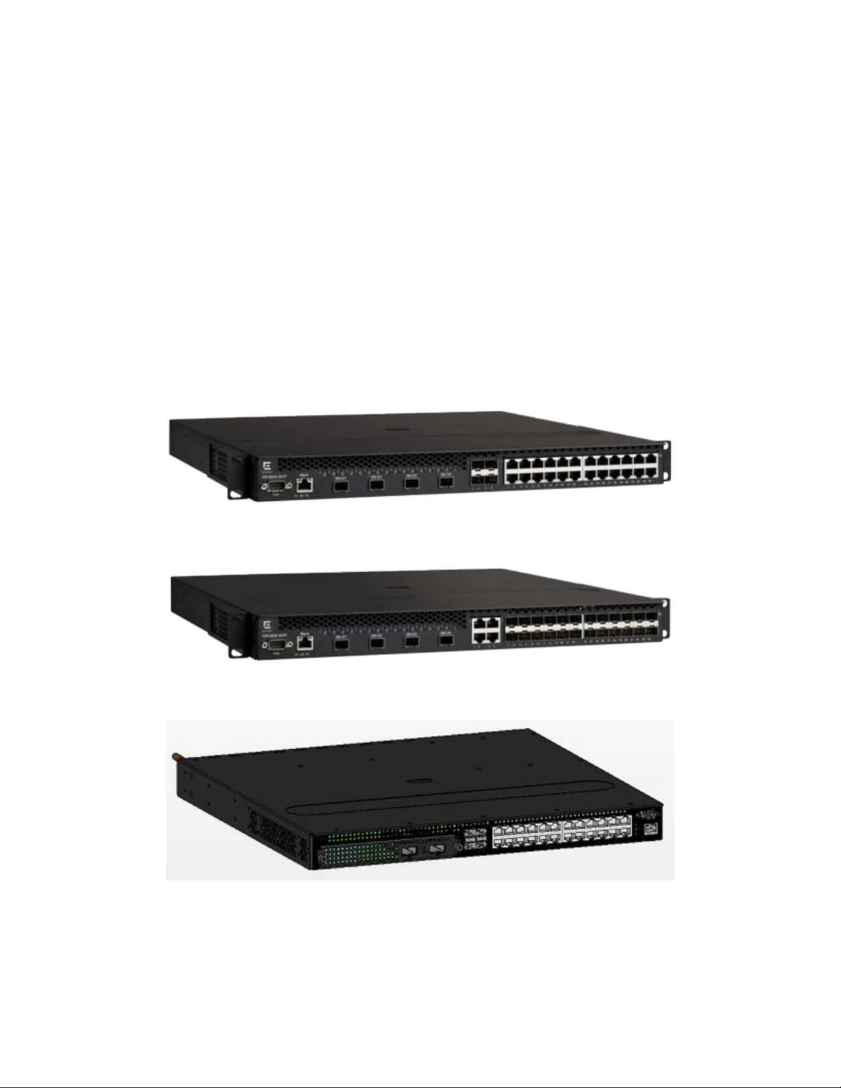
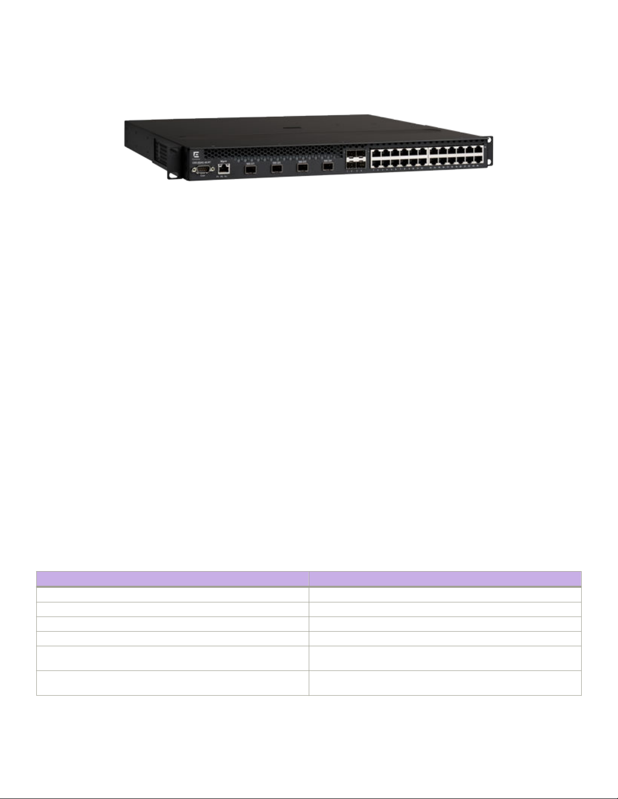
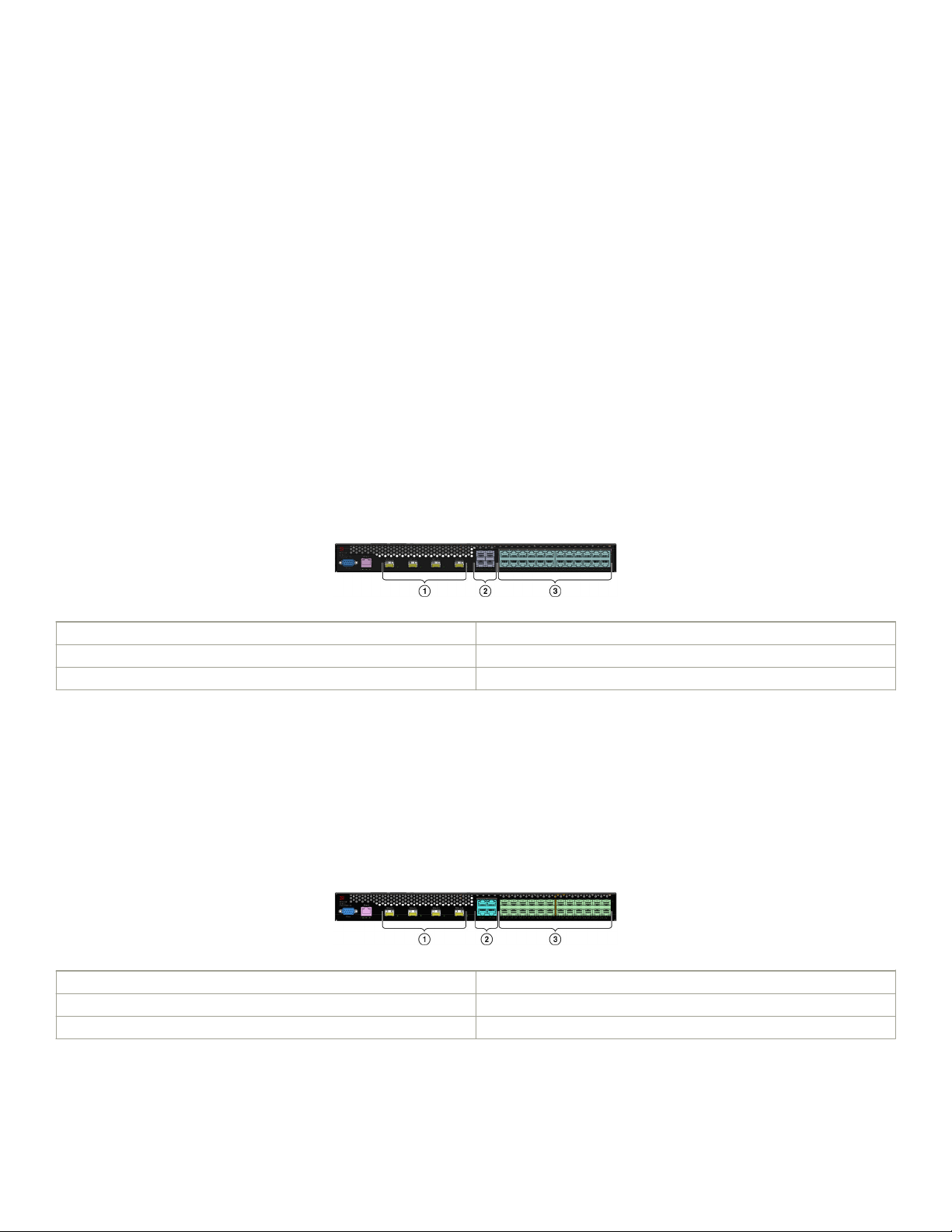
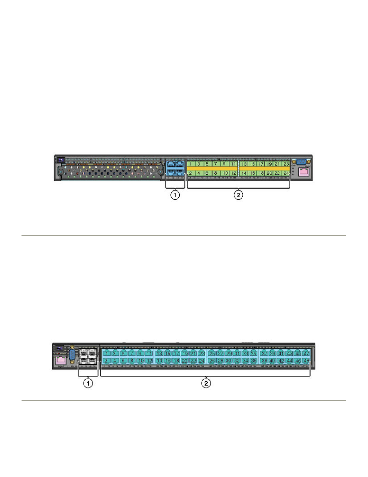
FIGURE 19 CES 2000 Series 2024C-4X device
1 10 GbE SFP+ ports
2 Four combination 100/1000 MbE SFP ports
3 Twenty-four 10/100/1000 MbE RJ45 ports
CES 2000 Series 2024F-4X
The CES 2000 Series 2024F-4X has twenty-four 100/1000 MbE SFP ports plus four combination 10/100/1000 MbE RJ45 ports,
4-port 10 GbE SFP+ module, one DB9 serial management interface port labeled Console, one 10/100/1000 MbE RJ45 out-of-band
management port, one resilient six-unit fan tray, and two AC power supply bays for 1+1 redundancy with one 500W AC power supply
included.
FIGURE 20 CES 2000 Series 2024F-4X device
1 10 GbE SFP+ ports
2 Four combination 10/100/1000 MbE RJ45 ports
3 Twenty-four 100/1000 MbE SFP ports
ExtremeSwitching CES 2000 Series and ExtremeRouting CER 2000 Series Hardware Installation Guide
9035631-01 21
Hardware features
CES 2000 Series 2024C
The CES 2000 Series 2024C switch has twenty-four 10/100/1000 MbE RJ45 ports plus four combination 100/ 1000 MbE SFP
ports, one module slot for an optional eld upgradable 2-port 10 GbE XFP module, one DB9 serial management interface port labeled
Console, one 10/100/1000 MbE RJ45 out-of-band management port, one resilient six-unit fan tray, and two AC power supply bays
for 1+1 redundancy with one 500W AC power supply included.
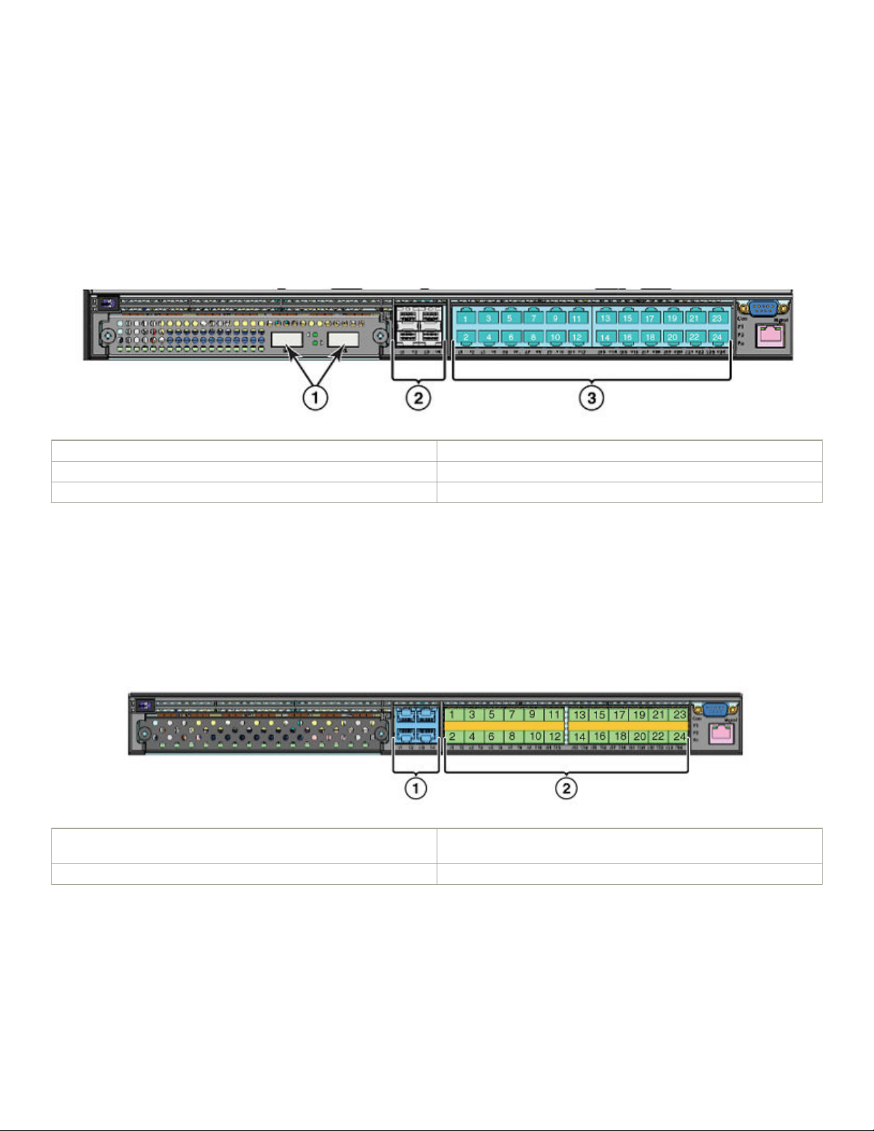
FIGURE 21 CES 2000 Series 2024C device with the optional 2 ports of 10-G XFP uplink
1 Optional 10 GbE XFP ports
2 Four combination 100/1000 MbE SFP ports
3 Twenty-four 10/100/1000 MbE RJ45 ports
CES 2000 Series 2024F
The CES 2000 Series 2024F has twenty-four 100/1000 MbE SFP ports plus four combination 10/100/1000 MbE RJ45 ports, one
module slot for an optional eld upgradable 2-port 10 GbE XFP module, one DB9 serial management interface port labeled Console,
one 10/100/1000 MbE RJ45 out-of-band management port, one resilient six-unit fan tray, and two AC power supply bays for 1+1
redundancy with one 500W AC power supply included.
FIGURE 22 CES 2000 Series 2024F device
1 Four combination 10/100/1000 MbE RJ45 ports with support for
optional 10Gbe XFP ports
2 Twenty-four 100/1000 MbE SFP ports
CES 2000 Series 2048C
CES 2000 Series 2048C (Copper) switch has forty-eight 10/100/1000 MbE RJ45 ports plus four combination 100/ 1000 MbE
SFP ports, one DB9 serial management interface port labeled Console, one 10/100/1000 MbE RJ45 out-of-band management port,
one resilient six-unit fan tray, and two AC power supply bays for 1+1 redundancy with one 500W AC power supply included.
22 9035631-01
ExtremeSwitching CES 2000 Series and ExtremeRouting CER 2000 Series Hardware Installation Guide
Hardware features
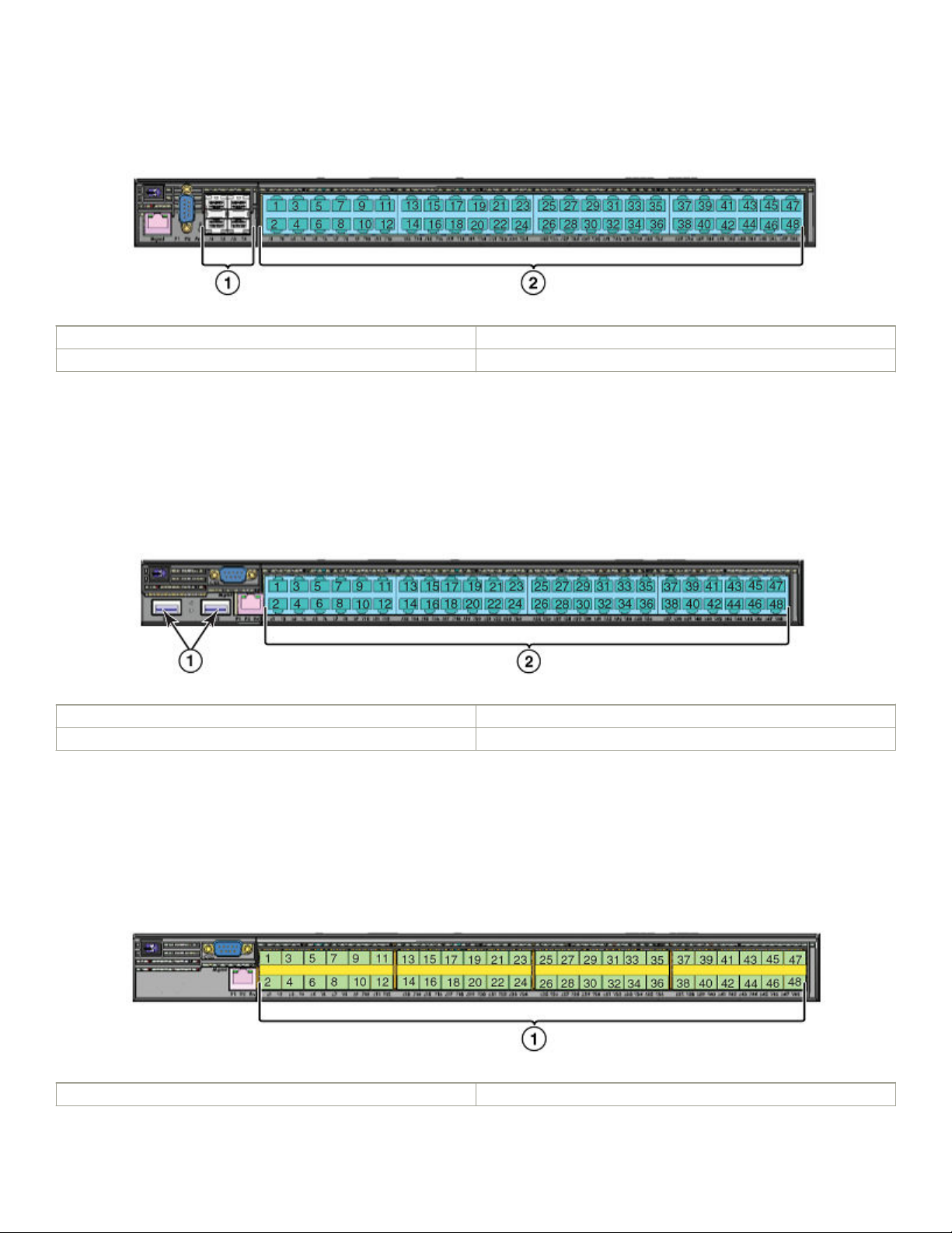
FIGURE 23 CES 2000 Series 2048C device
1 Four combination 100/1000 MbE SFP ports
2 Forty-eight 10/100/1000 MbE RJ45 ports
CES 2000 Series 2048CX
CES 2000 Series 2048CX (Copper) has forty-eight 10/100/1000 MbE RJ45 ports plus two 10 GbE XFP ports, one DB9 serial
management interface port labeled Console, one 10/100/1000 MbE RJ45 out-of-band management port, one resilient six-unit fan
tray, and two AC power supply bays for 1+1 redundancy with one 500W AC power supply included.
FIGURE 24 CES 2000 Series 2048CX device
1 10 GbE XFP ports
2 Forty-eight 10/100/1000 MbE RJ45 ports
CES 2000 Series 2048F
CES 2000 Series 2048F (Fiber) has forty-eight 100/1000 MbE SFP ports, one DB9 serial management interface port labeled
Console, one 10/100/1000 MbE RJ45 out-of-band management port, one resilient six-unit fan tray, and two AC power supply bays
for 1+1 redundancy with one 500W AC power supply included.
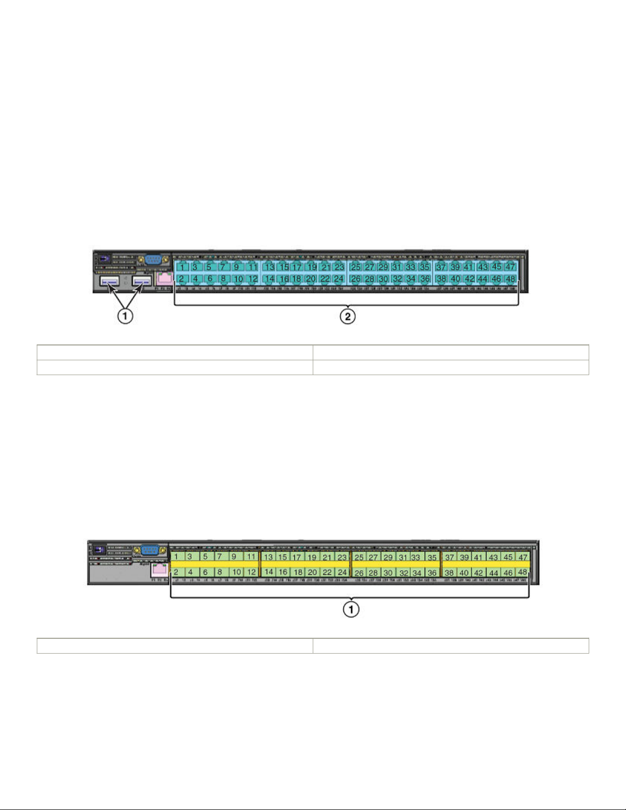
FIGURE 25 CES 2000 Series 2048F device
1 Forty eight 100/1000 MbE SFP ports
ExtremeSwitching CES 2000 Series and ExtremeRouting CER 2000 Series Hardware Installation Guide
9035631-01 23
Hardware features
CES 2000 Series 2048FX
CES 2000 Series 2048FX (Fiber) switch has forty-eight 100/1000 MbE SFP ports plus two 10 GbE XFP ports, one DB9 serial
management interface port labeled Console, one 10/100/1000 MbE RJ45 out-of-band management port, one resilient six-unit fan
tray, and two AC power supply bays for 1+1 redundancy with one 500W AC power supply included.
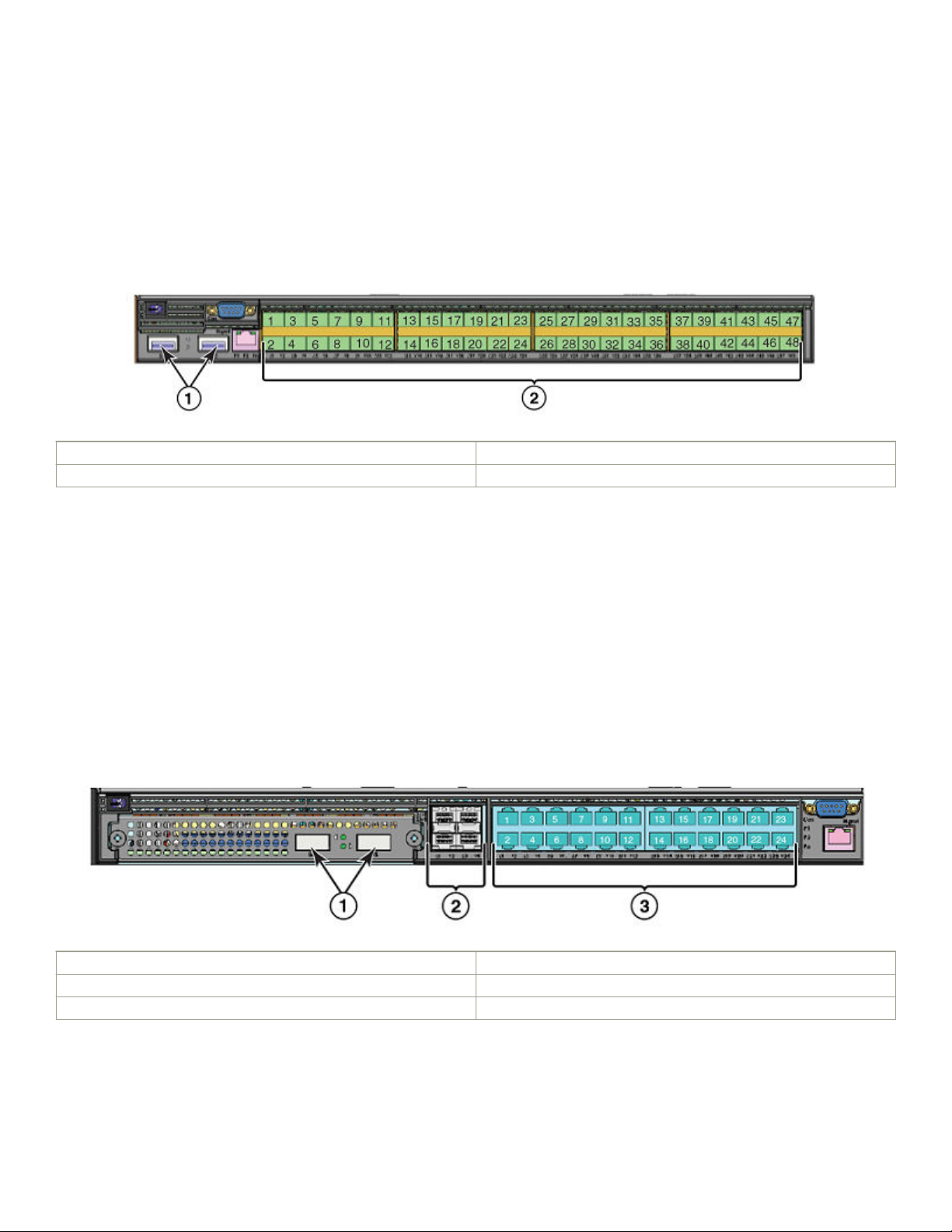
FIGURE 26 CES 2000 Series 2048FX device
1 10 GbE XFP ports
2 Forty eight 100/1000 MbE SFP ports
CER 2000 Series 2024C
The CER 2000 Series 2024C router has twenty-four 10/100/1000 MbE RJ45 ports plus four combination 100/ 1000 MbE SFP
ports, one module slot for an optional eld upgradable 2-port 10 GbE XFP module, one DB9 serial management interface port labeled
Console, one 10/100/1000 MbE RJ45 out-of-band management port, one resilient six-unit fan tray, and two AC power supply bays
for 1+1 redundancy with one 500W AC power supply included.
The CER 2000 Series-RT 2024C router has more memory to support 1.5M routes, twenty-four 10/100/1000 MbE RJ45 ports plus
four combination 100/ 1000 MbE SFP ports, one module slot for an optional eld upgradable 2-port 10 GbE XFP module, one DB9
serial management interface port labeled Console, one 10/100/1000 MbE RJ45 out-of-band management port, one resilient six-unit
fan tray, and two AC power supply bays for 1+1 redundancy with one 500W AC power supply included.
FIGURE 27 CER 2000 Series 2024C device with the optional 2 ports of 10-G XFP uplink
1 Optional 10 GbE XFP ports
2 Four combination 100/1000 MbE SFP ports
3 Twenty-four 10/100/1000 MbE RJ45 ports
24 9035631-01
ExtremeSwitching CES 2000 Series and ExtremeRouting CER 2000 Series Hardware Installation Guide
Hardware features
CER 2000 Series 2024F
The CER 2000 Series 2024F has twenty-four 100/1000 MbE SFP ports plus four combination 10/100/1000 MbE RJ45 ports, one
module slot for an optional eld upgradable 2-port 10 GbE XFP module, one DB9 serial management interface port labeled Console,
one 10/100/1000 MbE RJ45 out-of-band management port, one resilient six-unit fan tray, and two AC power supply bays for 1+1
redundancy with one 500W AC power supply included.
The CER 2000 Series-RT 2024F has more memory to support 1.5M routes, twenty-four 100/1000 MbE SFP ports plus four
combination 10/100/1000 MbE RJ45 ports, one module slot for an optional eld upgradable 2-port 10 GbE XFP module, one DB9
serial management interface port labeled Console, one 10/100/1000 MbE RJ45 out-of-band management port, one resilient six-unit
fan tray, and two AC power supply bays for 1+1 redundancy with one 500W AC power supply included.
FIGURE 28 CER 2000 Series 2024F device
1 Four combination 10/100/1000 MbE RJ45 ports with support for
optional 10Gbe XFP ports
2 Twenty-four 100/1000 MbE SFP ports.
CER 2000 Series 2048C
CER 2000 Series 2048C (Copper) router has forty-eight 10/100/1000 MbE RJ45 ports plus four combination 100/ 1000 MbE SFP
ports, one DB9 serial management interface port labeled Console, one 10/100/1000 MbE RJ45 out-of-band management port, one
resilient six-unit fan tray, and two AC power supply bays for 1+1 redundancy with one 500W AC power supply included.
CER 2000 Series-RT 2048C (Copper) router has more memory to support 1.5M routes, forty-eight 10/100/1000 MbE RJ45 ports
plus four combination 100/ 1000 MbE SFP ports, one DB9 serial management interface port labeled Console, one 10/100/1000
MbE RJ45 out-of-band management port, one resilient six-unit fan tray, and two AC power supply bays for 1+1 redundancy with one
500W AC power supply included.
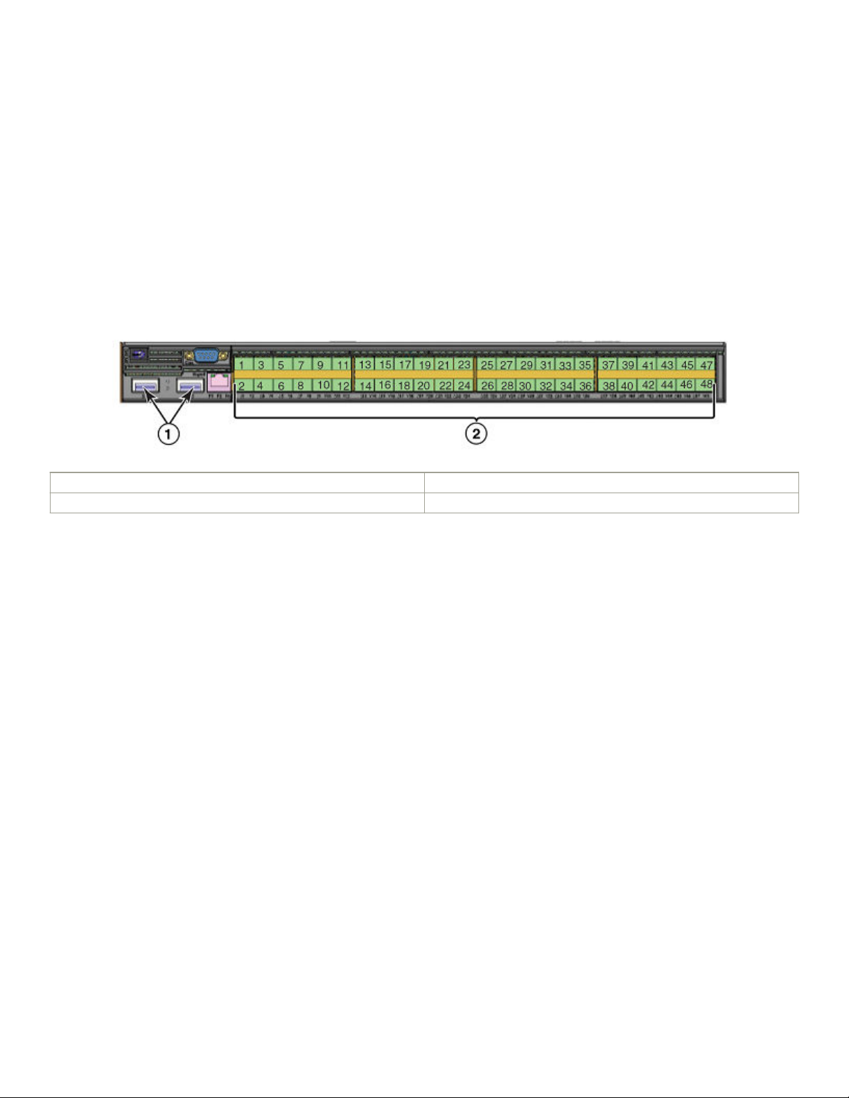
FIGURE 29 CER 2000 Series 2048C device
1 Four combination 100/1000 MbE SFP ports
2 Forty-eight 10/100/1000 MbE RJ45 ports
ExtremeSwitching CES 2000 Series and ExtremeRouting CER 2000 Series Hardware Installation Guide
9035631-01 25
Hardware features
CER 2000 Series 2048CX
CER 2000 Series 2048CX (Copper) has forty-eight 10/100/1000 MbE RJ45 ports plus two 10 GbE XFP ports, one DB9 serial
management interface port labeled Console, one 10/100/1000 MbE RJ45 out-of-band management port, one resilient six-unit fan
tray, and two AC power supply bays for 1+1 redundancy with one 500W AC power supply included.
CER 2000 Series-RT 2048CX (Copper) has more memory to support 1.5M routes, forty-eight 10/100/1000 MbE RJ45 ports plus
two 10 GbE XFP ports, one DB9 serial management interface port labeled Console, one 10/100/1000 MbE RJ45 out-of-band
management port, one resilient six-unit fan tray, and two AC power supply bays for 1+1 redundancy with one 500W AC power supply
included.
FIGURE 30 CER 2000 Series 2048CX device
1 10 GbE XFP ports
2 Forty-eight 10/100/1000 MbE RJ45 ports
CER 2000 Series 2048F
CER 2000 Series 2048F (Fiber) has forty-eight 100/1000 MbE SFP ports, one DB9 serial management interface port labeled
Console, one 10/100/1000 MbE RJ45 out-of-band management port, one resilient six-unit fan tray, and two AC power supply bays
for 1+1 redundancy with one 500W AC power supply included.
CER 2000 Series-RT 2048F (Fiber) has more memory to support 1.5M routes, forty-eight 100/1000 MbE SFP ports, one DB9 serial
management interface port labeled Console, one 10/100/1000 MbE RJ45 out-of-band management port, one resilient six-unit fan
tray, and two AC power supply bays for 1+1 redundancy with one 500W AC power supply included.
FIGURE 31 CER 2000 Series 2048F device
1 Forty eight 100/1000 MbE SFP ports
26 9035631-01
ExtremeSwitching CES 2000 Series and ExtremeRouting CER 2000 Series Hardware Installation Guide
Hardware features
CER 2000 Series 2048FX
CER 2000 Series 2048FX (Fiber) router has forty-eight 100/1000 MbE SFP ports plus two 10 GbE XFP ports, one DB9 serial
management interface port labeled Console, one 10/100/1000 MbE RJ45 out-of-band management port, one resilient six-unit fan
tray, and two AC power supply bays for 1+1 redundancy with one 500W AC power supply included.
CER 2000 Series-RT 2048FX (Fiber) router has more memory to support to support 1.5M routes, forty-eight 100/1000 MbE SFP
ports plus two 10 GbE XFP ports, one DB9 serial management interface port labeled Console, one 10/100/1000 MbE RJ45 out-ofband management port, one resilient six-unit fan tray, and two AC power supply bays for 1+1 redundancy with one 500W AC power
supply included.
FIGURE 32 CER 2000 Series 2048FX device
1 10 GbE XFP ports
2 Forty eight 100/1000 MbE SFP ports
Control features
The front panel on each device has a combination of the following control features:
• Serial Management Interface (the port labeled Console)
• 10/100/1000 ports with RJ-45 copper connectors
• 100/1000 Hybrid Fiber (HF) ports
• 100/1000 ports with mini-GBIC slots for SFP MSA-compliant ber transceivers
• Each device that optionally has up to two 10-Gigabit Ethernet uplink ports, supports 10-Gigabit Small Form Factor Pluggable
(XFP) MSA-compliant optical transceivers
• Each device that has four 10-Gigabit Ethernet uplink ports, supports 10-Gigabit Small Form Factor Pluggable (SFP+) MSAcompliant optical transceivers
Serial Management Interface (console port)
The Serial Management Interface enables you to
a directly connected PC. A straight-through EIA/TIA DB-9 serial cable (M/F) ships with the device. The serial management interface (the
port labeled Console) is located in the front panel.
congure and manage the device using a third-party terminal emulation application on
Port LEDs
The ports on the devices provide status information using the LEDs listed in Table 3 and Table 4.
ExtremeSwitching CES 2000 Series and ExtremeRouting CER 2000 Series Hardware Installation Guide
9035631-01 27

Hardware features
TABLE 3 LEDs for 10/100/1000 Mbps ports
LED Position State Meaning
10/100/1000 Port LEDs
Lnk/Act Bottom Left On Link is up.
O Link is down.
Blinking Port is transmitting or receiving
trac
Lnk/Act Bottom Right On Link is up.
O Link is down.
Blinking Port is transmitting or receiving
trac
NOTE
The LEDs are located beneath the port connector.
TABLE 4 LEDs for 10-Gbps Ethernet ports
LED Port State Meaning
10-Gbps Port LEDs on devices with two 10-Gbps ports
Top Left hand port On The port is connected.
O No ber port connection exists.
Blinking Trac is being transmitted and
received on the ber port
Bottom Right hand port On The port is connected.
O No ber port connection exists.
Blinking Trac is being transmitted and
received on the ber port
10-Gbps Port LEDs on devices with four 10-Gbps ports
Top Left hand port On The port is connected.
O No ber port connection exists.
Blinking Trac is being transmitted and
received on the ber port
Bottom Right hand port On The port is connected.
O No ber port connection exists.
Blinking Trac is being transmitted and
received on the ber port
NOTE
The LEDs are located adjacent to the port connector.
Network interfaces
This section describes the port types in the CES 2000 Series, CER 2000 Series devices.
10/100/1000 Mbps ports
The 10/100/1000 ports on the device use auto-sensing and auto-negotiating to determine the speed (10 Mbps, 100 Mbps, or 1000
Mbps) and duplex mode (full-duplex or half-duplex) of the port at the other end of the link and adjust port speed accordingly.
28 9035631-01
ExtremeSwitching CES 2000 Series and ExtremeRouting CER 2000 Series Hardware Installation Guide

Hardware features
Combination ports
On devices with combination (combo) ports, one port out of each pair of copper and ber ports can be active at a time. Combo ports are
numbered 1-4. For example, you can use either copper port 2 or ber port 2, but not both at the same time. You can use a combination
of ber and copper ports or all copper or all ber ports, as needed.
If you attach both the copper and ber connectors for a port to the network, the ber connectors take precedence over the copper
connectors. These ports support true media automatic detection, meaning the device selects the ber or copper connector based on link
availability. If a ber link cannot be established, the device selects the copper media.
10-Gbps ports
The CES 2000 Series 2048C-4X, CES 2000 Series 2048F-4X, CER 2000 Series 2048C-4X-RT, and the CER 2000 Series
2048F-4X-RT come with four 10-Gigabit Ethernet ports installed. The four 10-Gigabit Ethernet uplink ports support 10-Gigabit Small
Form Factor Pluggable (SFP+) MSA-compliant optical transceivers
The CES 2000 Series 2048CX, CES 2000 Series 2048FX, CER 2000 Series 2048CX, and the CER 2000 Series 2048FX come
with two 10-Gigabit Ethernet ports installed. A 24-port CES 2000 Series, CER 2000 Series has a slot to accommodate a 2-port 10Gigabit Ethernet module. If your 24-port device does not include a 10-GbE module, you can optionally install one. Refer to 10-Gbps
ports. The two 10-Gigabit Ethernet ports use 10-Gigabit Small Form Factor Pluggable (XFP) MSA-compliant transceivers.
Supported optics
100/1000 Ethernet Ports
The Ethernet Interface module contains 24 or 48 physical ports, through which you can connect your device to other network devices at
a speed of 100 Mbps or 1 Gbps.
Into a physical port, you must insert a
provide an optical transceiver or physical medium-dependent (PMD) interface for ber that can be used with the LAN physical layer
(PHY)
The following 100 Mbps and 1 GbE optical transceivers are available from Extreme Networks:
TABLE 5 SFP-compliant transceivers for the 100/1000 Ethernet interface module
Part number Description
E1MG-TX SFP Copper, RJ-45 connector
E1MG-SX 1000Base-SX SFP optic, multi-mode ber, LC connector
E1MTG-SX 1000Base-SX SFP optic, multi-mode ber, MTRJ connector
E1MG-SX2-1310 1310 1000Base-SX SFP optic multi-mode ber, LC connector and
E1MG-LX 1000Base-LX SFP optic, single-mode ber, LC connector
E1MG-LHA 1000Base-LHA SFP optic, single-mode ber, LC connector
E1MG-LHB 1000Base-LHB SFP optic, single-mode ber, LC connector, 150km
E1MG-BXD 1000Base-BXD SFP optic single-mode ber, 1490nm, LC connector.
E1MG-CWDM80-1470 CWDM SFP optic, 80km, 1470nm, LC connector
E1MG-CWDM80-1490 CWDM SFP optic, 80Km, 1490nm, LC connector
E1MG-CWDM80-1510 CWDM SFP optic, 80Km, 1510nm, LC connector
ber-optic transceiver provided by Extreme Networks. The SFP-compliant ber-optic modules
support for distances up to 2km
Maximum Reach
This optic can only be connected to an E1MG-BXU
ExtremeSwitching CES 2000 Series and ExtremeRouting CER 2000 Series Hardware Installation Guide
9035631-01 29

Hardware features
TABLE 5 SFP-compliant transceivers for the 100/1000 Ethernet interface module (continued)
Part number Description
E1MG-CWDM80-1530 CWDM SFP optic, 80Km, 1530nm, LC connector
E1MG-CWDM80-1550 CWDM SFP optic, 80Km, 1550nm, LC connector
E1MG-CWDM80-1570 CWDM SFP optic, 80Km, 1570nm, LC connector
E1MG-CWDM80-1590 CWDM SFP optic, 80Km, 1590nm, LC connector
E1MG-CWDM80-1610 CWDM SFP optic, 80Km, 1610nm, LC connector
E1MG-100FX 100Base-FX SFP optic multi-mode ber, LC connector
E1MG-100FX-IR 100BaseFX-IR optic for SMF with LC connector. For distances up to
15nm.
E1MG-100FX-LR 100BaseFX-LR SFP optic for SMF with LC connector. For distances up
to 40km.
10 Gigabit Ethernet ports
A 10 Gigabit Ethernet module contains two or four physical ports, through which you can connect your device to other network devices
at a speed of 10 Gigabits.
Into a physical port, you must insert a ber-optic transceiver provided by device. The XFP/SFP+-compliant ber-optic modules provide
an optical transceiver or physical medium-dependent (PMD) interface for single or multi-mode ber that can be used with the LAN
physical layer (PHY).
The following 10 Gigabit optics are available from device.
TABLE 6 MSA-compliant Optics for the 10 GbE Ethernet interface module
Part number Description
Devices with up to two 10GbE ports (XFP)
10G-XFP-SR 850nm serial pluggable XFP optic, target range 300m over multi-mode
ber
10G-XFP-LR 1310nm serial pluggable XFP optic for up to 10km over single-mode
ber
10G-XFP-ER 1550nm serial pluggable XFP optic for up to 40km over single-mode
ber
10G-XFP-ZR 1550nm serial pluggable XFP optic for up to 80km over single-mode
ber
10G-XFP-ZRD 10GBase-ZR DWDM, XFP optic, 80km, 1530.33 to 1561.42
10G-XFP-CX4 10-Base-CX4, XFP transceiver, 15km, CX connector
Devices with up to four 10GbE ports (SFP+)
10G-SFPlus-SR
10G-SFPlus-LR
10G-SFPlus-ZR
10G-SFPlus-ZRD
Port regions
Ports on the devices are grouped into regions. For a few features, such as port monitoring and unknown unicast congurations, you will
need to know the region to which a port belongs. However, for most features, a port’s region does not aect conguration or operation of
the feature. If a port’s region does aect conguration or operation of a feature, it is noted and described in the appropriate feature
section of this guide.
30 9035631-01
ExtremeSwitching CES 2000 Series and ExtremeRouting CER 2000 Series Hardware Installation Guide
 Loading...