

Page 1

Summit 200 Series Switch
Installation and User Guide
Software Version 7.1e0
Extreme Networks, Inc.
3585 Monroe Street
Santa Clara, California 95051
(888) 257-3000
http://www.extremenetworks.com
Part Number: 100149-00 Rev 02
December, 2003
Page 2

©2003 Extreme Networks, Inc. All rights reserved. Extreme Networks, ExtremeWare and BlackDiamond are registered
trademarks of Extreme Networks, Inc. in the United States and certain other jurisdictions. ExtremeWare Vista,
ExtremeWorks, ExtremeAssist, ExtremeAssist1, ExtremeAssist2, PartnerAssist, Extreme Standby Router Protocol, ESRP,
SmartTraps, Alpine, Summit, Summit1, Summit4, Summit4/FX, Summit7i, Summit24, Summit48, Summit Virtual
Chassis, SummitLink, SummitGbX, SummitRPS and the Extreme Networks logo are trademarks of Extreme Networks,
Inc., which may be registered or pending registration in certain jurisdictions. The Extreme Turbodrive logo is a service
mark of Extreme Networks, which may be registered or pending registration in certain jurisdictions. Specifications are
subject to change without notice.
NetWare and Novell are registered trademarks of Novell, Inc. Merit is a registered trademark of Merit Network, Inc.
Solaris is a trademark of Sun Microsystems, Inc. F5, BIG/ip, and 3DNS are registered trademarks of F5 Networks, Inc.
see/IT is a trademark of F5 Networks, Inc.
“Data Fellows”, the triangle symbol, and Data Fellows product names and symbols/logos are
trademarks of Data Fellows.
F-Secure SSH is a registered trademark of Data Fellows.
All other registered trademarks, trademarks and service marks are property of their respective owners.
ii
Page 3

Contents
Preface
Introduction xiii
Conventions xiv
Related Publications xiv
Chapter 1 Summit 200 Series Switch Overview
Summit 200 Series Switches 15
Summary of Features 15
Summit 200-24 Switch Physical Features 16
Summit 200-24 Switch Front View 16
Summit 200-24 Switch Rear View 19
Summit 200-48 Switch Physical Features 19
Summit 200-48 Switch Front View 19
Summit 200-48 Switch Rear View 22
Mini-GBIC Type and Hardware/Software Support 23
Mini-GBIC Type and Specifications 23
Chapter 2 Switch Installation
Determining the Switch Lo cation 27
Following Safety Information 28
Installing the Switch 28
Rack Mounting 28
Free-Standing 29
Desktop Mounting of Multiple Switches 29
Installing or Replacing a Mini-Gig abit Interface Connector (Mini-GBIC) 29
Safety Information 29
Preparing to Install or Replace a Mini-GBIC 29
Removing and Inserting a Mini-GBIC 30
Summit 200 Series Switch Installation and User Guide iii
Page 4

Contents
Creating a Stack 31
Connecting Equipment to the Console Port 32
Powering On the Switch 34
Checking the Installation 34
Logging In for the First Time 34
Chapter 3 ExtremeWare Overview
Summary of Features 37
Virtual LANs (VLANs) 38
Spanning Tree Protocol 38
Quality of Service 39
Unicast Routing 39
Load Sharing 39
ESRP-Aware Switches 39
Software Licensing 40
Feature Licensing 40
Security Licensing for Features Under License Control 41
SSH2 Encryption 41
Software Factory Defaults 42
Chapter 4 Accessing the Switch
Understanding the Command Syntax 45
Syntax Helper 46
Command Shortcuts 46
Summit 200 Series Switch Numerical Ranges 46
Names 47
Symbols 47
Line-Editing Keys 47
Command History 48
Common Commands 48
Configuring Management Access 50
User Account 50
Administrator Account 51
Default Accounts 51
Creating a Management Account 52
Domain Name Service Client Services 53
Checking Basic Connectivity 54
Ping 54
Traceroute 54
iv Summit 200 Series Switch Installation and User Guide
Page 5

Chapter 5 Managing the Switch
Overview 57
Using the Console Interface 58
Using Telnet 58
Connecting to Another Host Using Telnet 58
Configuring Switch IP Parameters 58
Disconnecting a Telnet Session 60
Controlling Telnet Access 61
Using Secure Shell 2 (SSH2) 61
Enabling SSH2 61
Using SNMP 62
Accessing Switch Agents 62
Supported MIBs 62
Configuring SNMP Settings 62
Displaying SNMP Settings 64
Contents
Authenticating Users 64
RADIUS Client 64
Configuring TACACS+ 69
Network Login 71
Web-Based and 802.1x Authentication 71
Campus and ISP Modes 73
Interoperability Requirements 74
Multiple Supplicant Support 75
Exclusions and Limitations 75
Configuring Network Login 76
Web-Based Authentication User Login Using Campus Mode 77
DHCP Server on the Switch 79
Displaying DHCP Information 79
Displaying Network Login Settings 79
Disabling Network Login 79
Additional Configuration Details 79
Network Login Configuration Commands 80
Displaying Network Login Settings 81
Disabling Network Login 81
Using EAPOL Flooding 81
Using the Simple Network Time Protocol 82
Configuring and Using SNTP 82
SNTP Configuration Commands 85
SNTP Example 85
Chapter 6 Configuring Ports on a Switch
Enabling and Disabling Switch Ports 87
Summit 200 Series Switch Installation and User Guide v
Page 6

Contents
Configuring Switch Port Speed and Duplex Setting 88
Switch Port Commands 89
Load Sharing on the Switch 91
Load-Sharing Algorithms 92
Configuring Switch Load Sharing 93
Load-Sharing Example 93
Verifying the Load-Sharing Configuration 94
Switch Port-Mirroring 94
Port-Mirroring Commands 95
Port-Mirroring Example 95
Setting Up a Redundant Gigabit Uplink Port 95
Extreme Discovery Protocol 95
EDP Commands 96
Chapter 7 Virtual LANs (VLANs)
Overview of Virtual LANs 97
Benefits 97
Ty p es of VLANs 9 8
Port-Based VLANs 98
Ta g ged VLANs 100
VLAN Names 102
Default VLAN 102
Renaming a VLAN 103
Configuring VLANs on the Switch 103
VLAN Configuration Commands 103
VLAN Configuration Examples 104
Displaying VLAN Settings 104
MAC-Based VLANs 105
MAC-Based VLAN Guidelines 105
MAC-Based VLAN Limitations 106
MAC-Based VLAN Example 106
Timed Configuration Download for MAC-Based VLANs 106
Chapter 8 Forwarding Database (FDB)
Overview of the FDB 109
FDB Contents 109
FDB Entry Types 109
How FDB Entries Get Added 110
Associating a QoS Profile with an FDB Entry 110
Configuring FDB Entries 111
FDB Configuration Examples 111
vi Summit 200 Series Switch Installation and User Guide
Page 7

Displaying FDB Entries 112
Chapter 9 Access Policies
Overview of Access Policies 115
Access Control Lists 115
Rate Limits 115
Routing Access Policies 116
Using Access Control Lists 116
Access Masks 116
Access Lists 116
Rate Limits 117
How Access Control Lists Work 118
Access Mask Precedence Numbers 118
Specifying a Default Rule 118
The permit-established Keyword 118
Adding Access Mask, Access List, and Rate Limit Entries 119
Deleting Access Mask, Access List, and Rate Limit Entries 120
Verifying Access Control List Configurations 120
Access Control List Commands 120
Access Control List Examples 124
Contents
Using Routing Access Policies 128
Creating an Access Profile 128
Configuring an Access Profile Mode 128
Adding an Access Profile Entry 128
Deleting an Access Profile Entry 129
Applying Access Profiles 129
Routing Access Policies for RIP 129
Routing Access Policies for OSPF 131
Making Changes to a Routing Access Policy 132
Removing a Routing Access Policy 132
Routing Access Policy Commands 133
Chapter 10 Network Address Translation (NAT)
Overview 135
Internet IP Addressing 136
Configuring VLANs for NAT 136
NAT Modes 1 37
Configuring NAT 138
Configuring NAT Rules 138
Creating NAT Rules 139
Creating Static and Dynamic NAT Rules 139
Summit 200 Series Switch Installation and User Guide vii
Page 8

Contents
Creating Portmap NAT Rules 139
Creating Auto-Constrain NAT Rules 140
Advanced Rule Matching 140
Configuring Timeouts 141
Displaying NAT Settings 141
Disabling NAT 142
Chapter 11 Ethernet Automatic Protection Switching
Overview of the EAPS Protocol 143
Optimizing Interoperability 145
Fault Detection and Recovery 145
Restoration Operations 146
Summit 200 Series Switches in Multi-ring Topologies 147
Commands for Configuring and Monitoring EAPS 148
Creating and Deleting an EAPS Domain 149
Defining the EAPS Mode of the Switch 149
Configuring EAPS Polling Timers 149
Configuring the Primary and Secondary Ports 150
Configuring the EAPS Control VLAN 151
Configuring the EAPS Protected VLANs 151
Enabling and Disabling an EAPS Domain 152
Enabling and Disabling EAPS 152
Unconfiguring an EAPS Ring Port 152
Displaying EAPS Status Information 152
Chapter 12 Quality of Service (QoS)
Overview of Policy-Based Quality of Service 157
Applications and Types of QoS 158
Video Applications 158
Critical Database Applications 158
Web Browsing Applications 158
File Server Applications 159
Configuring QoS for a Port or VLAN 159
Tr af fic Gr ou pin gs 15 9
Access List Based Traffic Groupings 160
MAC-Based Traffic Groupings 160
Explicit Class of Service (802.1p and DiffServ) Traffic Groupings 161
Configuring DiffServ 163
Physical and Logical Groupings 166
Verifying Configuration and Performance 167
QoS Monitor 167
Displaying QoS Profile Information 167
viii Summit 200 Series Switch Installation and User Guide
Page 9

Modifying a QoS Configuration 168
Traffic Rate-Limiting 168
Dynamic Link Context System 168
DLCS Guidelines 169
DLCS Limitations 169
DLCS Commands 169
Chapter 13 Status Monitoring and Statistics
Status Monitoring 171
Port Statistics 173
Port Errors 173
Port Monitoring Display Keys 174
Setting the System Recovery Level 175
Logging 175
Local Logging 176
Remote Logging 177
Logging Configuration Changes 178
Logging Commands 178
Contents
RMON 179
About RMON 179
RMON Features of the Switch 180
Configuring RMON 181
Event Actions 1 81
Chapter 14 Spanning Tree Protocol (STP)
Overview of the Spanning Tree Protocol 183
Spanning Tree Domains 183
Defaults 184
STPD BPDU Tunneling 184
STP Configurations 184
Configuring STP on the Switch 186
STP Configuration Example 189
Displaying STP Settings 189
Disabling and Resetting STP 189
Chapter 15 IP Unicast Routing
Overview of IP Unicast Routing 191
Router Interfaces 192
Populating the Routing Table 193
Subnet-Directed Broadcast Forwarding 194
Summit 200 Series Switch Installation and User Guide ix
Page 10

Contents
Proxy ARP 194
ARP-Incapable Devices 195
Proxy ARP Between Subnets 1 95
Relative Route Priorities 195
Configuring IP Unicast Routing 196
Verify ing the IP Unicast Routing Configuration 196
IP Commands 197
Routing Configuration Example 201
Displaying Router Settings 202
Resetting and Disabling Router Settings 203
Configuring DHCP/BOOTP Relay 204
Verifying the DHCP/BOOTP Relay Configuration 204
UDP-Forwarding 205
Configuring UDP-Forwarding 205
UDP-Forwarding Example 205
ICMP Packet Processing 206
UDP-Forwarding Commands 206
Chapter 16 Interior Gateway Routing Protocols
Overview 207
RIP Versus OSPF 208
Overview of RIP 208
Routing Table 209
Split Horizon 209
Poison Reverse 209
Triggered Updates 209
Route Advertisement of VLANs 209
R IP Ve rsi on 1 Vers us RIP Vers ion 2 209
Overview of OSPF 210
Link-State Database 210
Areas 211
Point-to-Point Support 214
Route Re-Distribution 215
Configuring Route Re-Distribution 215
OSPF Timers and Authentication 216
Configuring RIP 217
RIP Configuration Example 219
Displaying RIP Settings 220
Resetting and Disabling RIP 220
Configuring OSPF 220
x Summit 200 Series Switch Installation and User Guide
Page 11

Configuring OSPF Wait Interval 225
Displaying OSPF Settings 226
OSPF LSD Display 226
Resetting and Disabling OSPF Settings 227
Chapter 17 IP Multicast Routing and IGMP Snooping
IP Multicast Routing Overview 229
PIM Sparse Mode (PIM-SM) Overview 230
Configuring PIM-SM 230
Enabling and Disabling PIM-SM 231
PIM-SM Commands 232
IGMP Overview 233
Configuring IGMP and IGMP Snooping 234
Displaying IGMP Snooping Configuration Information 235
Contents
Clearing, Disabling, and Resetting IGMP Fu nctions 235
Chapter 18 Configuring Stacked Switches
Introducing Stacking 237
Configuring a Stack 238
Creating a Backup Configuration 238
Enabling the Master 238
Enabling a Stack Member 239
Configuring Ports and VLANS on Stacks 240
Recovering a Stack 242
Changing a Stack Configuration 243
Stack Configuration Commands 244
Running Features on a Stack 245
Testing Images for a Stack 245
Using the Console for Managing the Stack 246
Setting the Command Prompt 246
Chapter 19 Using ExtremeWare Vista
on the Summit 200
ExtremeWare Vista Overview 247
Setting Up Your Browser 247
Accessing ExtremeWare Vista 248
Navigating within ExtremeWare Vista 250
Browser Controls 251
Summit 200 Series Switch Installation and User Guide xi
Page 12

Contents
Status Messages 251
Configuring the Summit 200 using ExtremeWare Vista 251
IP Forwarding 252
License 253
OSPF 254
Ports 261
RIP 263
SNMP 266
Spanning Tree 267
Switch 271
User Accounts 271
Vir t u a l L AN 2 7 2
Reviewing ExtremeWare Vista Statistical Re ports 274
Event Log 275
FDB 276
IP ARP 277
IP Configuration 278
IP Route 280
IP Statistics 281
Ports 283
Port Collisions 284
Port Errors 285
Port Utilization 286
RIP 287
Switch 288
Locating Support Information 289
Help 289
TFTP Download 290
Logging Out of ExtremeWare Vista 293
Appendix A Safety Information
Important Safety Information 295
Power 295
Power Cord 296
Connections 296
Lithium Battery 296
Appendix B Technical Specifications
Summit 200-24 Switch 299
Summit 200-48 Switch 302
Appendix C Supported Standards
xii Summit 200 Series Switch Installation and User Guide
Page 13

Appendix D Software Upgrade and Boot Options
Downloading a New Image 307
Rebooting the Switch 308
Saving Configuration Changes 309
Returning to Factory Defaults 310
Using TFTP to Upload the Configuration 310
Using TFTP to Download the Configuration 311
Downloading a Complete Configuration 311
Downloading an Incremental Configuration 311
Scheduled Incremental Configuration Download 311
Remember to Save 312
Upgrading and Accessing BootROM 3 12
Upgrading BootROM 312
Accessing the BootROM menu 312
Boot Option Commands 313
Contents
Appendix E Troubleshooting
LEDs 233
Using the Command-Line Interface 234
Port Configuration 235
VLANs 236
STP 237
Debug Tracing 237
TOP Command 237
Contacting Extreme Technical Support 237
Index
Index of Commands
Summit 200 Series Switch Installation and User Guide xiii
Page 14

Contents
xiv Summit 200 Series Switch Installation and User Guide
Page 15

Preface
This preface provides an overview of this guide, describes guide conventions, and lists other
publications that may be useful.
Introduction
This guide provides the required information to install the Summit 200 series switch and configure the
ExtremeWare
This guide is intended for use by network administrators who are responsible for installing and setting
up network equipment. It assumes a basic working knowledge of:
• Local area networks (LANs)
• Ethernet concepts
• Ethernet switching and bridging concepts
• Routing concepts
• Internet Protocol (IP) concepts
• Simple Network Management Protocol (SNMP)
NOTE
If the information in the release notes shipped with your switch differs from the information in this guide,
follow the release notes.
™
software running on the Summit 200 series switch.
Summit 200 Series Switch Installation and User Guide xiii
Page 16

Conventions
Table 1 and Table2 list conventions that are used throughout this guide.
Table 1: Notice Icons
Icon Notice Type Alerts you to...
Note Important features or instructions.
Caution Risk of personal injury, system damage, or loss of data.
Warning Risk of severe personal injury.
Table 2: Te x t C on v en ti on s
Convention Description
Screen displays This typeface indicates command syntax, or represents information as
it appears on the screen.
The words “enter”
and “type”
[Key] names Key names are written with brackets, such as [Return] or [Esc].
Words in italicized type Italics emphasize a point or denote new terms at the place where th ey
When you see the word “enter” in this guide, you must type something,
and then press the Return or Enter key. Do not press the Return or
Enter key when an instruction simply says “type.”
If you must press two or more keys simultaneously, the key names are
linked with a plus sign (+). Example:
Press [Ctrl]+[Alt]+[Del].
are defined in the text.
Related Publications
The publications related to this one are:
• ExtremeWare Release Notes
• Summit 200 Series Switch Release Notes
Documentation for Extreme Networks products is available on the World Wide Web at the following
location:
• http://www.extremenetworks.com/
xiv Summit 200 Series Switch Installation and User Guide
Page 17

1 Summit 200 Series Switch Overview
This chapter describes the features and functionality of the Summit 200 series switches:
• Summit 200 Series Switches on page 15
• Summary of Features on page 15
• Summit 200-24 Switch Physical Features on page 16
• Summit 200-48 Switch Physical Features on page 19
• Mini-GBIC Type and Hardware/Software Support on page 23
Summit 200 Series Switches
The Summit 200 series switches include the following swi tch models:
• Summit 200-24 switch
• Summit 200-48 switch
Summary of Features
The Summit 200 series switches support the following ExtremeWare features:
• Virtual local area networks (VLANs) including support for IEEE 802.1Q and IEEE 802.1p
• Spanning Tree Protocol (STP) (IEEE 802.1D)
• Quality of Service (QoS) including support for IEEE 802.1p, MAC QoS, and f our hardware queues
• Wire-speed Internet Protocol (IP) routing
• DHCP/BOOTP Relay
• Network Address Translation (NAT)
• Extreme Standby Router Protocol (ESRP) - Aware support
• Ethernet Automated Protection Switching (EAPS) support
• Routing Information Protocol (RIP) version 1 and RIP version 2
• Open Shortest Path First (OSPF) routing protocol
• DiffServ support
Summit 200 Series Switch Installation and User Guide 15
Page 18
Summit 200 Series Switch Overview
e
• Access-policy support for routing protocols
• Access list support for packet filtering
• Access list support for rate-limiting
• IGMP snooping to control IP multicast traffic
• Load sharing on multiple ports
• RADIUS client and per-command authentication support
• TACACS+ support
• Network login
• Console command-line interface (CLI) connection
• Telnet CLI connection
• SSH2 connection
• Simple Network Management Protocol (SNMP) support
• Remote Monitoring (RMON)
• Traffic mirroring for ports
Summit 200-24 Switch Physical Features
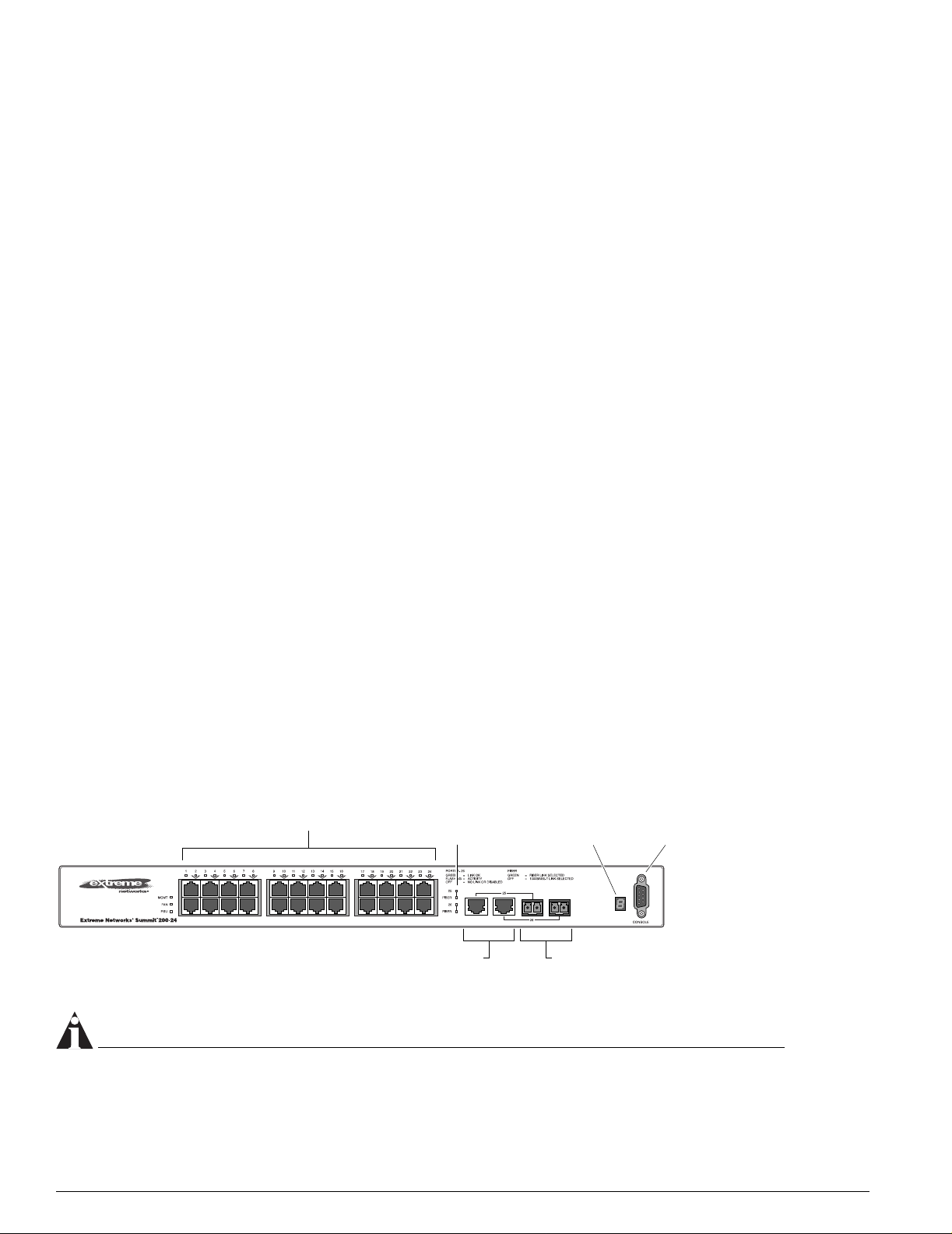
The Summit 200-24 switch is a compact enclosure (see Figure 1) one rack unit in height (1.75 inches or
44.45 mm) that provides 24 autosensing 10BASE-T/100BASE-TX ports using RJ-45 connectors. It also
provides two 10/100/1000BASE-T Gigabit Ethernet uplink ports using RJ-45 connectors and two optical
ports that also allow Gigabit Ethernet uplink connections through Extreme 1000BASE-SX, 1000BASE-LX,
or 1000BASE-ZX Small Form Factor pluggable (SFP) Gigabit Interface Connectors (GBICs)—also known
as mini-GBICs—using LC optical fiber connectors.
Summit 200-24 Switch Front View
Figure 1 shows the Summit 200-24 switch front view.
Figure 1: Summit 200-24 switch front view
10/100 Mbps ports
Mini-GBIC
port status LEDs
Unit stacking
ID LED
Mini-GBIC ports1000-baseT ports
Consol
port
LC24001A
NOTE
See Table 5 for information about supported mini-GBIC types and distances.
16 Summit 200 Series Switch Installation and User Guide
Page 19

Summit 200-24 Switch Physical Features
NOTE
See “Summit 200-24 Switch LEDs” on page 18 for more details.
Console Port
Use the console port (9-pin, “D” type connector) for connecting a terminal and carrying out local
management.
Port Connections
The Summit 200-24 switch has 24 10BASE-T/100BASE-TX ports using RJ-45 connectors for
communicating with end stations and other devices over 10/100Mbps Ethernet.
The switch also has four Gigabit Ethernet uplink ports. These ports are labeled 25 and 26 on the front
panel of the switch. Two of the ports are 10/100/1000BASE-T ports using RJ-45 connectors. The other
two ports are unpopulated receptacles for mini-SFP GBICs, using optical fibers with LC connectors. The
Summit 200-24 switch supports the use of 1000BASE-SX, 1000BASE-LX, or 1000BASE-ZX mini-GBICs.
NOTE
Only mini-GBICs that have been certified by Extreme Networks (available from Extreme Networks)
should be inserted into the mini-GBIC receptacles on the Summit 200 series switch.
Only two of the four Gigabit Ethernet uplink ports can be active at one time. For example, you can use
both 1000BASE-T ports, both mini-GBIC ports, or a combination of one 1000BASE-T port and one
mini-GBIC.
NOTE
For information on the mini-GBIC, see “Mini-GBIC Type and Hardware/Software Support” on page 23.
Summit 200-24 Switch Uplink Redundancy
Gigabit Ethernet uplink redundancy on the Summit 200-24 switch follows these rules:
• Ports 25 and 26 are Gigabit Ethernet ports that have redundant PHY interfaces, one mini-GBIC and
one 1000BASE-T connection for each port.
• Each of the uplink Gigabit Ethernet ports (25 and 26) can use either the m ini-GBIC or the
1000BASE-T interface, but not both simultaneously.
• Only one interface on each port can be active at a time. For example, on port 25, with both the
mini-GBIC and 1000BASE-T interfaces connected, only one interface can be activated. The other is
inactive. If both interfaces are connected, the switch defaults to the fiber interface (mini-GBIC) and
deactivates the 1000BASE-T interface.
• If only one interface is connected, the switch activates the connected interface.
• To set up a redundant link on port 25, connect the active fibre and 1000BASE-T links to both the
RJ-45 and mini-GBIC interfaces of port 25. The switch defaults to the fi ber link. If the fiber link fails
during operation, the switch automatically activates the redundant 1000BASE-T link.
Summit 200 Series Switch Installation and User Guide 17
Page 20

Summit 200 Series Switch Overview
NOTE
To suppor t automatic failover between the fiber and copper ports, you must use an Extreme mini-GBIC
connector.
Full-Duplex
The Summit 200-24 switch provides full-duplex support for all ports. Full-duplex allows frames to be
transmitted and received simultaneously and, in effect, doubles the bandwidth available on a link. All
10/100 Mbps ports on the Summit 200-24 switch autonegotiate for half- or full-duplex operation.
Summit 200-24 Switch LEDs
Table 3 describes the light emitting diode (LED) behavior on the Summit 200-24 switch.
Table 3: Summit 200-24 switch LED behavior
Unit Status LED (MGMT LED)
Color Indicates
Green slow
blinking
Green fast
blinking
Amber
Fan LED
Color Indicates
Green
Amber blinking
Port Status LEDs (Ports 1–26)
Color Indicates
Green
Green blinking
Off
Media-Selection (Fiber) LEDs (Ports 25 and 26)
Color Indicates
Green
Off
Unit Stacking ID Number LED
The Summit switch is operating normally.
The Summit switch POST is in progress.
The Summit switch has failed its POST or an overheat condition
is detected.
The fan is operating normally.
A failed condition is present on the fan.
Link is present; port is enabled.
Link is present, port is enabled, and there is activity on the port.
Link is not present or the port is disabled.
Fiber link is selected; mini-GBIC is present and being used for the
Gigabit Ethernet uplink.
1000BASE-T link is selected; the switch is using the RJ-45 port
for the Gigabit Ethernet uplink.
Color Indicates
0 N/A Either stacking is not enabled or the stack is down.
1 N/A The switch is the stack master.
2-8 N/A The switch is a member of the stack.
18 Summit 200 Series Switch Installation and User Guide
Page 21
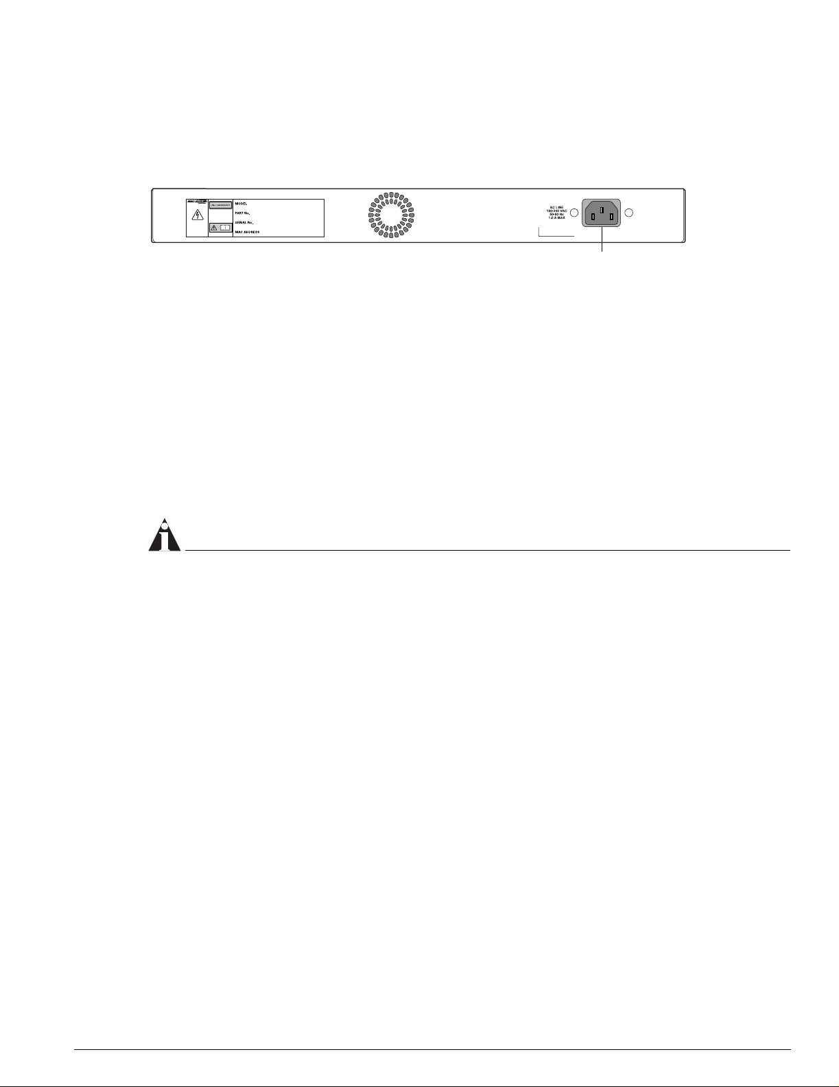
Summit 200-24 Switch Rear View
Figure 2 shows the rear view of the Sum mit 200-24 switch.
Figure 2: Summit 200-24 switch rear view
Summit 200-48 Switch Physical Features
Power socket
LC24002
Power Socket
The Summit 200-24 switch automatically adjusts to the supply voltage. The power supply operates
down to 90 V.
Serial Number
Use this serial number for fault-reporting purposes.
MAC Address
This label shows the unique Ethernet MAC address assigned to this device.
NOTE
The Summit 200-24 switch certification and safety label is located on the bottom of the switch.
Summit 200-48 Switch Physical Features
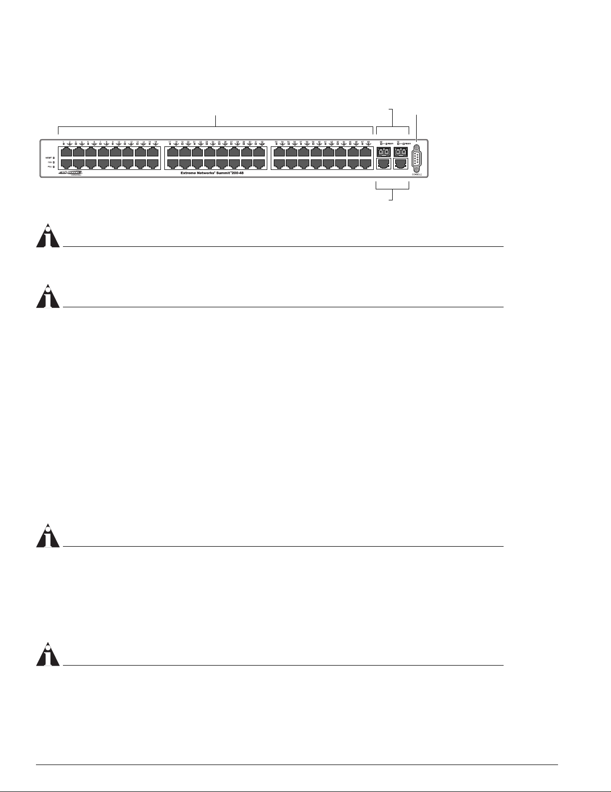
The Summit 200-48 switch is a compact enclosure (see Figure 3) one rack unit in height (1.75 inches or
44.45 mm) that provides 48 autosensing 10BASE-T/100BASE-TX ports using RJ-45 connectors. It also
provides two 10/100/1000BASE-T Gigabit Ethernet uplink ports using RJ-45 connectors and two optical
ports that also allow Gigabit Ethernet uplink connections through Extreme 1000BASE-SX, 1000BASE-LX,
or 1000BASE-ZX SFP mini-GBICs using optical fibers with LC connectors.
Summit 200-48 Switch Front View
Figure 3 shows the Summit 200-48 switch front view.
Summit 200 Series Switch Installation and User Guide 19
Page 22
Summit 200 Series Switch Overview
e
Figure 3: Summit 200-48 switch front view
10/100 Mbps ports
Mini-GBIC ports
1000-baseT ports
Consol
port
LC48001
NOTE
See Table 5 for information about supported mini-GBIC types and distances.
NOTE
See “Summit 200-48 Switch LEDs” on page 22 for more details.
Console Port
Use the console port (9-pin, “D” type connector) for connecting a terminal and carrying out local
management.
Port Connections
The Summit 200-48 switch has 48 10BASE-T/100BASE-TX ports using RJ-45 connectors for
communicating with end stations and other devices over 10/100Mbps Ethernet.
The switch also has four Gigabit Ethernet uplink ports. These ports are labeled 49 and 50 on the front
panel of the switch. Two of the ports are 10/100/1000BASE-T ports using RJ-45 connectors. The other
two ports are unpopulated receptacles for mini-SFP GBICs, using optical fibers with LC connectors. The
Summit 200-48 switch supports the use of 1000BASE-SX, 1000BASE-LX, or 1000BASE-ZX mini-GBICs.
NOTE
Only mini-GBICs that have been certified by Extreme Networks (available from Extreme Networks)
should be inserted into the mini-GBIC receptacles on the Summit 200 series switch.
Only two of the four Gigabit Ethernet uplink ports can be active at one time. For example, you can use
both 1000BASE-T ports, both mini-GBIC ports, or a combination of one 1000BASE-T port and one
mini-GBIC.
NOTE
For information on the mini-GBIC, see “Mini-GBIC Type and Hardware/Software Support” on page 23.
20 Summit 200 Series Switch Installation and User Guide
Page 23

Summit 200-48 Switch Physical Features
NOTE
When configuring the Summit 200-48 switch, all ports specified as mirrored ports and mirroring por t, or
ACL ingress ports and egress port, must belong to the same port group. Port group 1 consists of ports
1 through 24 and port 49; port group 2 consists of ports 25 through 48 and port 50.
Gigabit Ethernet Port Failover Speed
The Summit 200-48 switch Gigabit Ethernet port failover from the fiber link to the copper link takes 3-4
seconds. The Summit 200-48 switch Gigabit Ethernet port failover from the co pper link to the fiber link
takes 1-2 seconds.
Summit 200-48 Switch Uplink Redundancy
Gigabit Ethernet uplink redundancy on the Summit 200-48 switch follows these rules:
• Ports 49 and 50 are Gigabit Ethernet ports that have redundant PHY interfaces, one mini-GBIC and
one 1000BASE-T connection for each port.
• Each of the uplink Gigabit Ethernet ports (49 and 50) can use either the m ini-GBIC or
the1000BASE-T interface, but not both simultaneously.
• Only one interface on each port can be active at a time. For example, on port 49, with both the
mini-GBIC and 1000BASE-T interfaces connected, only one interface can be activated. The other is
inactive. If both interfaces are connected, the switch defaults to the fiber interface (mini-GBIC) and
deactivates the 1000BASE-T interface.
• If only one interface is connected, the switch activates the connected interface.
• To set up a redundant link on port 49, connect the active fibre and 1000BASE-T links to both the
RJ-45 and mini-GBIC interfaces of port 49. The switch defaults to the fi ber link. If the fiber link fails
during operation, the switch automatically activates the redundant 1000BASE-T link.
NOTE
To suppor t automatic failover between the fiber and copper ports, you must use an Extreme mini-GBIC
connector.
Full-Duplex
The Summit 200-48 switch provides full-duplex support for all ports. Full-duplex allows frames to be
transmitted and received simultaneously and, in effect, doubles the bandwidth available on a link. All
10/100 Mbps ports on the Summit 200-48 switch autonegotiate for half- or full-duplex operation.
Summit 200 Series Switch Installation and User Guide 21
Page 24

Summit 200 Series Switch Overview
Summit 200-48 Switch LEDs
Table 4 describes the LED behavior on the Summit 200-48 switch.
Table 4: Summit 200-48 switch LED behavior
Unit Status LED (MGMT LED)
Color Indicates
Green slow
blinking
Green fast
blinking
Amber
Fan LED
Color Indicates
Green
Amber blinking
Port Status LEDs (Ports 1–50)
Color Indicates
Green
Green blinking
Off
The Summit switch is operating normally.
The Summit switch POST is in progress.
The Summit switch has failed its POST or an overheat condition
is detected.
The fan is operating normally.
A failed condition is present on the fan.
Link is present; port is enabled.
Link is present, port is enabled, and there is activity on the port.
Link is not present or the port is disabled.
Media-Selection (Fiber) LEDs (Ports 49 and 50)
Color Indicates
Green
Off
Fiber link is selected; mini-GBIC is present and being used for the
Gigabit Ethernet uplink.
1000BASE-T link is selected; the switch is using the RJ-45 port
for the Gigabit Ethernet uplink.
Summit 200-48 Switch Rear View
Figure 4 shows the rear view of the Summit 200-48 switch.
Figure 4: Summit 200-48 switch rear view
Power socket
Power Socket
The Summit 200-48 switch automatically adjusts to the supply voltage. The power supply operates
down to 90 V.
LC48002
22 Summit 200 Series Switch Installation and User Guide
Page 25

Mini-GBIC Type and Hardware/Software Support
Serial Number
Use this serial number for fault-reporting purposes.
MAC Address
This label shows the unique Ethernet MAC address assigned to this device.
NOTE
The Summit 200-48 switch certification and safety label is located on the bottom of the switch.
Mini-GBIC Type and Hardware/Software Support
The Summit 200 series switch supports the SFP GBIC, also known as the mini-GBIC, in three types: the
SX mini-GBIC, which conforms to the 1000BASE-SX st andard, the LX mini-GBIC, which conforms to the
1000BASE-LX standard, and the ZX mini-GBIC, a long-haul mini-GBIC that conforms to the IEEE 802.3z
standard. The system uses identifier bits to determine the media type of the mini-GBIC that is installed.
The Summit 200 series switches support only the SFP mini-GBIC.
NOTE
Only mini-GBICs that have been certified by Extreme Networks (available from Extreme Networks)
should be inserted into the mini-GBIC receptacles on the Summit 200 series switch.
This section describes the mini-GBIC types and specifications.
Mini-GBIC Type and Specifications
Table 5 describes the mini-GBIC type and distances for the Summit 200 series switches.
Table 5: Mini-GBIC types and distances
Maximum
Distance
(Meters)
500
550
220
275
550
550
550
5,000
Standard Media Type
1000BASE-SX
(850 nm optical window)
1000BASE-LX
(1310 nm optical window)
50/125 µm multimode fiber
50/125 µm multimode fiber
62.5/125 µm multimode fiber
62.5/125 µm multimode fiber
50/125 µm multimode fiber
50/125 µm multimode fiber
62.5/125 µm multimode fiber
10/125 µm single-mode fiber
Mhz•Km
Rating
400
500
160
200
400
500
500
—
1000BASE-ZX
(1550 nm optical window)
Summit 200 Series Switch Installation and User Guide 23
10/125 µm single-mode fiber — 50,000
Page 26

Summit 200 Series Switch Overview
SX Mini-GBIC Specifications
Table 6 describes the specifications for the SX mini-GBIC .
Table 6: SX mini-GBIC specifications
Parameter Minimum Typical Maximum
Transceiver
Optical output power –9.5 dBm –4 dBm
Center wavelength 830 nm 850 nm 860 nm
Receiver
Optical input power sensitivity –21 dBm
Optical input power maximum –4 dBm
Operating wavelength 830 nm 860 nm
General
Total system budget 11.5 dB
Total optical system budget for the SX mini-GBIC is 11.5 dB. Extreme Networks recommends that 3 dB
of the total budget be reserved for losses induced by cable splices, connectors, and operating margin.
While 8.5 dB remains available for cable-induced attenuation, the 1000BASE-SX standard specifies
supported distances of 275 meters over 62.5 micron multimode fiber and 550 meters over 50 micron
multimode fiber. There is no minimum attenuation or minimum cable length restriction.
LX Mini-GBIC Specifications
Table 7 describes the specifications for the LX mini-GBIC.
Table 7: LX mini-GBIC specifications
Parameter Minimum Typical Maximum
Transceiver
Optical output power –9.5 dBm –3 dBm
Center wavelength 1275 nm 1310 nm 1355 nm
Receiver
Optical input power sensitivity –23 dBm
Optical input power maximum –3 dBm
Operating wavelength 1270 nm 1355 nm
General
Total system budget 13.5 dB
Total optical system budget for the LX mini-GBIC is 13.5 dB. Measure cable plant losses with a 1310 nm
light source and verify this to be within budget. When calculating the maximum distance attainable
using optical cable with a specified loss per kilometer (for example 0.25 dB/km) Extreme Networks
recommends that 3 dB of the total budget be reserved for losses induced by cable splices, connectors,
and operating margin. Thus, 10.5 dB remains available for cable induced attenuation. There is no
minimum attenuation or minimum cable length restriction.
24 Summit 200 Series Switch Installation and User Guide
Page 27
1
ZX Mini-GBIC Specifications
Table 8 describes the specifications for the ZX mini-GBIC.
Table 8: ZX mini-GBIC specifications
Parameter Minimum Typical Maximum
Transceiver
Optical output power –2 dBm 0dBm 3dBm
Center wavelength 1540 nm 1550 nm 1570 nm
Receiver
Optical input power sensitivity –23 dBm
Optical input power maximum –3 dBm
Operating wavelength 1540 nm 1550 nm 1570 nm
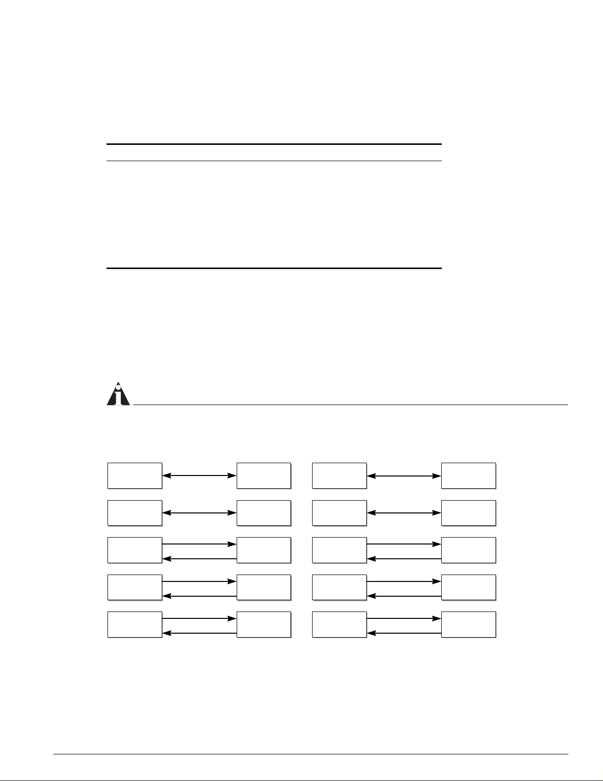
Long Range GBIC System Budgets
Mini-GBIC Type and Hardware/Software Support
Measure cable plant losses with a 1550 nm light source and verify this to be within budget. When
calculating the maximum distance attainable using optical cable with a specified loss per kilometer (for
example 0.25 dB/km), Extreme Networks recommends that 3 dB of the total budget be reserved for
losses induced by cable splices, connectors, and operating margin. Figure 5 shows the total optical
system budget between long range GBICs in various end-to-end combinations (ZX, ZX Rev 03, LX70,
and LX100).
NOTE
The ZX mini-GBIC is equivalent to the ZX Rev 03 GBIC.
Figure 5: Total optical system budgets for long range GBICs
ZX GBIC ZX GBIC
LX70 LX70
LX70
ZX GBIC LX70
19.5 dB
22.0 dB
23.0 dB
20.0 dB
18.0 dB
23.5 dB
ZX GBIC
Rev. 03
ZX GBIC
Rev. 03
LX100 LX100
LX70 LX100
ZX GBIC
21.0 dB
30.0 dB
29.0 dB
23.0 dB
25.0 dB
24.5 dB
ZX GBIC
Rev. 03
LX100
19.0 dB
ZX GBIC
Summit 200 Series Switch Installation and User Guide 25
21.5 dB
ZX GBIC
Rev. 03
ZX GBIC
Rev. 03
27.0 dB
24.0 dB
LX100
XM_04
Page 28

Summit 200 Series Switch Overview
Table 9 lists the minimum attenuation requirements to prevent saturation of the receiver for each type of
long range GBIC.
Table 9: Minimum attenuation requirements
Receivers
ZX (prior to
Rev 03)
ZX Rev 03 ZX mini
Transceivers
GBIC Type LX70 LX100
LX70 9 dB 13 dB 7 dB 7 dB 9 dB
LX100 8 dB 12 dB 6 dB 6 dB 8 dB
ZX (prior to
2 dB 6 dB 0 dB 0 dB 2 dB
Rev 03)
ZX Rev 03 5 dB 9 dB 3 dB 3 dB 5 dB
ZX mini 6 dB 10 dB 4 dB 4 dB 6 dB
26 Summit 200 Series Switch Installation and User Guide
Page 29

2 Switch Installation
This chapter describes the following topics:
• Determining the Switch Location on page 27
• Following Safety Information on page 28
• Installing the Switch on page 28
• Creating a Stack on page 31
• Installing or Replacing a Mini-Gigabit Interface Connector (Mini-GBIC) on page 29
• Connecting Equipment to the Console Port on page 32
• Powering On the Switch on page34
• Checking the Installation on page 34
• Logging In for the First Time on page 34
CAUTION
Use of controls or adjustments of pe rformance or procedures other t han those specified herein can
result in hazardous radiation exposure.
Determining the Switch Location
The Summit 200 series switch is suited for use in the office, where it can be free-standing or mounted in
a standard 19-inch equipment rack. Alternately, the device can be rack-mounted in a wiring closet or
equipment room. Two mounting bracke ts are supplied with the switch.
When deciding where to install the switch, ensure that:
• The switch is accessible and cables can be connected easily.
• Water or moisture cannot enter the case of the unit.
• Air-flow around the unit and through the vents in the side of the case is not restricted. You should
provide a minimum of 1 inch (25 mm) clearance.
• No objects are placed on top of the unit.
• Units are not stacked more than four high if the switch is free-standing.
Summit 200 Series Switch Installation and User Guide 27
Page 30
Switch Installation
Following Safety Information
Before installing or removing any components of the switch, or before carrying out any maintenance
procedures, read the safety information provided in w of this guide.
Installing the Switch
The Summit 200 series switch switch can be mounted in a rack, or placed free-standing on a tabletop.
Rack Mounting
CAUTION
Do not use the rack mount kits to suspend the switch from under a table or desk, or to attach the switch
to a wall.
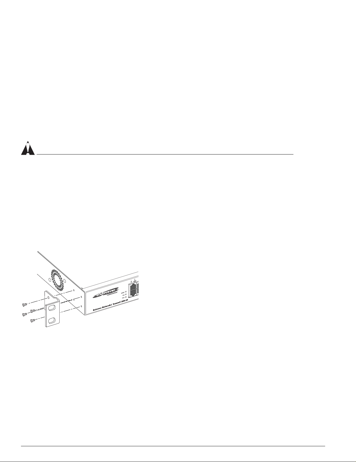
To rack mount the Summit 200 series switch:
1 Place the switch upright on a hard flat surface, with the front facing you.
2 Remove the existing screws from the sides of the case (retain the screws for Step 4).
3 Locate a mounting bracket over the mounting holes on one side of the unit.
4 Insert the screws and fully tighten with a suitable screwdriver, as shown in Figure 6.
Figure 6: Fitting the mounting bracket
LC24003
5 Repeat steps 2 through 4 for the other side of the switch.
6 Insert the switch into the 19-inch rack.
7 Secure the switch with suitable screws (not provided).
8 Connect the switch to the redundant power supply (if applicable).
9 Connect cables.
28 Summit 200 Series Switch Installation and User Guide
Page 31

Installing or Replacing a Mini-Gigabit Interface Connector (Mini-GBIC)
Free-Standing
The Summit 200 series switch is supplied with four self-adhesive rubber pads. Apply the pads to the
underside of the device by sticking a pad in the marked area at each corner of the switch.
Desktop Mounting of Multiple Switches
You can physically place up to four Summit switches on top of one another.
NOTE
This relates only to stacking the devices directly one on top of one another.
Apply the pads to the underside of the device by sticking a pad at each corner of the switch. Place the
devices on top of one another, ensuring that the corners align.
Installing or Replacing a Mini-Gigabit Interface Connector
(Mini-GBIC)
This section describes the safety precautions and preparation steps that you must perform before
inserting and securing a mini-GBIC.
Safety Information
Befo re you inst all o r rep lace a min i-G BIC, read the safety information in this section.
WARNING!
Mini-GBICs can emit invisible laser radiation. Avoid direct eye exposure to beam.
Mini-GBICs are a class 1 laser device. Use only devices approved by Extreme Networks.
NOTE
Remove the LC fiber-optic connector from the mini-GBIC prior to removing the mini-GBIC from the
switch.
Preparing to Install or Replace a Mini-GBIC
To ensure proper installation, complete the following tasks before inserting the mini-GBIC:
• Disable the port that is needed to install or replace the mini-GBIC.
• Inspect and clean the fiber tips, coupler, and connectors.
• Prepare and clean an external attenuator, if needed.
• Do not stretch the fiber.
Summit 200 Series Switch Installation and User Guide 29
Page 32

Switch Installation
4
• Make sure the bend radius of the fiber is not less than 2 inches.
In addition to the previously described tasks, Extreme Networks recommends the following when
installing or replacing mini-GBICs on an active network:
• Use the same type of mini-GBIC at each end of the link.
• Connect one end of the link to the Tx port. Without an attenuator, measure the total loss from the Tx
port to the other side of the link.
Once you complete all of the described tasks, you are ready to install or replace a mini-GBIC.
Removing and Inserting a Mini-GBIC
You can remove mini-GBICs from, or insert mini-GBICs into your Summit 200 series switch without
powering off the system. Figure 7 shows the two typ es of mini-GBIC modules.
Figure 7: Mini-GBIC modules
Module A Module B
XM_02
Mini-GBICs are a 3.3 V Class 1 laser device. Use only devices approved by Extreme Networks.
WARNING!
Mini-GBICs can emit invisible laser radiation. Avoid direct eye exposure to beam.
NOTE
Remove the LC fiber-optic connector from the mini-GBIC prior to removing the mini-GBIC from the
switch.
NOTE
If you see an amber blinking Mini-GBIC port status LED on your Summit 200 series switch, the
mini-GBIC installed in your switch is one that is not approved or supported by Extreme Networks. To
correct this problem, ensure that you install a mini-GBIC that is approved and supported by Extreme
Networks.
30 Summit 200 Series Switch Installation and User Guide
Page 33

Creating a Stack
Removing a Mini-GBIC
To remove a mini-GBIC similar to the one labeled “Module A” in Figure 7, gently press and hold the
black plastic tab at the bottom of the connector to release the mini-GBIC, and pull the mini-GBIC out of
the SFP receptacle on the switch.
To remove a mini-GBIC similar to the one labeled “Module B” in Figure 7, rotate the front handle down
and pull the mini-GBIC out of the slot.
Inserting a Mini-GBIC
NOTE
Mini-GBICs can be installed in the SFP mini-GBIC receptacles for ports 25 and 26 on the Summit 200
series switches.
To insert a mini-GBIC connector:
1 Holding the mini-GBIC by its sides, insert the mini-GBIC into the SFP receptacle on the switch.
2 Push the mini-GBIC into the SFP receptacle until you hear an audible click, indicating the mini-GBIC
is securely seated in the SFP receptacle. If the mini-GBIC has a handle, push up on the handle to
secure the mini-GBIC.
Creating a Stack
You can physically cable as many as eight Summit 200 switches together to create a virtual chassis
called as stack. You can mix any combination of Summit 200-24 and Summit 200-48 within the stack. The
high-speed one Gigabit Ethernet ports are the backplane of the stack and are called stacking ports. By
creating a stack, users can access and manage the devices using a single IP address.
The stacking configuration retains a high speed port on the end switches as uplinks to the network.
However, these uplink ports may not be configured to be in a load share group. Load sharing is only
supported for ports on the same switch. An example of a stacking configuration is shown in Figure 8.
Summit 200 Series Switch Installation and User Guide 31
Page 34

Switch Installation
Figure 8: Stacking Summit 200-48
To upstream
routers and switches
To downstream
switches
ES2K001
Connecting Equipment to the Console Por t
Connection to the console port is used for direct local management. The switch console port settings are
set as follows:
• Baud rate—9600
•Data bits—8
•Stop bit—1
• Parity—None
• Flow control—None
NOTE
If you set the switch console port flow control to XON/XOFF rather than None, you will be unable to
access the switch. Do not set the switch console port flow control to XON/XOFF.
The terminal connected to the console port on the switch must be configured with the same settings.
This procedure is described in the documentation supplied with the terminal.
32 Summit 200 Series Switch Installation and User Guide
Page 35

C
S
le
1
C
S
le
2
Connecting Equipment to the Console Port
Appropriate cables are available from your local supplier. To make your own cables, pinouts for a DB-9
male console connector are described in Table 10.
Table 10: Console Connector Pinouts
Function Pin Number Direction
DCD (data carrier detect) 1 In
RXD (receive data) 2 In
TXD (transmit data) 3 Out
DTR (data terminal ready) 4 Out
GND (ground) 5 —
DSR (data set ready) 6 In
RTS (request to send) 7 Out
CTS (clear to send 8 In
Figure 9 shows the pin-outs for a 9-pin to RS-232 25-pin null-modem cable.
Figure 9: Null-modem cable pin-o uts
ummit
able connector: 9-pin female
Screen
TxD
RxD
Ground
RTS
CTS
DSR
DCD
DTR
Shell
3
2
5
7
8
6
1
4
PC/Terminal
Cable connector: 25-pin male/fema
Screen
1
3
2
7
4
20
5
6
8
RxD
TxD
Ground
RTS
DTR
CTS
DSR
DCD
ser_sum
Figure 10 shows the pin-outs for a 9-pin to 9-pin PC-AT null-modem serial cable.
Figure 10: PC-AT serial null-modem cable pin-outs
ummit
able connector: 9-pin female
Screen
DTR
TxD
RxD
CTS
Ground
DSR
RTS
DCD
Shell
4
3
2
8
5
6
7
1
PC-AT Serial Port
Cable connector: 9-pin fema
Screen
Shell
1
2
3
4
5
6
7
8
DCD
RxD
TxD
DTR
Ground
DSR
RTS
CTS
ser_sum
Summit 200 Series Switch Installation and User Guide 33
Page 36

Switch Installation
Powering On the Switch
To turn on power to the switch, connect the AC power cable to the switch and then to the wall outlet.
Turn the on/off switch to the on position.
Checking the Installation
After turning on power to the Summit 200 series switch, the device performs a Power On Self-Test
(POST).
During the POST, all ports are temporarily disabled, the port LED is off, and the MGMT LED flashes.
The MGMT LED flashes until the switch successfully passes the POST.
If the switch passes the POST, the MGMT LED is blinking slowly (once per second). If the switch fails
the POST, the MGMT LED is amber.
NOTE
For more information on the LEDs, see Chapter 1, “Summit 200 Series Switch Overview”.
Logging In for the First Time
After the Summit 200 series switch completes the POST, it is operational. Once operational, you can log
in to the switch and configure an IP address for the default VLAN (named default).
To configure the IP settings manually, follow these steps:
1 Connect a terminal or workstation running terminal-emulation software to the console port.
2 At your terminal, press [Return] one or more times until you see the login prompt.
3 At the login prompt, enter the default user name admin to log on with administrator privileges.
For example:
login: admin
Administrator capabilities allow you to access all switch functions.
NOTE
For more information on switch security, see Chapter 4, “Accessing the Switch”.
4 At the password prompt, press [Return].
The default name, admin, has no password assigned. When you have successfully logged on to the
switch, the command-line prompt displays the name of the switch (for example, Summit200-24) in its
prompt.
5 Assign an IP address and subnetwork mask for VLAN default by typing
config vlan default ipaddress 123.45.67.8 255.255.255.0
Your changes take effect immediately.
6 Save your configuration changes so that they will be in effect after the next switch reboot, by typing
34 Summit 200 Series Switch Installation and User Guide
Page 37

Logging In for the First Time
save
NOTE
For more information on saving configuration changes, see the ExtremeWare Software User Guide.
7 When you are finished using the facility, logout of the switch by typing
logout
NOTE
After two incorrect login attempts, the Summit 200 series switch locks you out of the login facility. You
must wait a few minutes before attempting to log in again.
Summit 200 Series Switch Installation and User Guide 35
Page 38

Switch Installation
36 Summit 200 Series Switch Installation and User Guide
Page 39

3 ExtremeWare Overview
This chapter describes the following topics:
• Summary of Features on page 37
• Software Licensing on page 40
• Security Licensing for Features Under License Control on page 41
• Software Factory Defaults on page 42
ExtremeWare is the full-featured software oper ating system that is designed to run on the Summit 200
series switch. This section describes the supported ExtremeWare features for the Summit 200 series
switch.
Summary of Features
The Summit 200 series switch supports the following ExtremeWare features:
• Virtual local area networks (VLANs) including support for IEEE 802.1Q and IEEE 802.1p
• Spanning Tree Protocol (STP) (IEEE 802.1D)
• Quality of Service (QoS) including support for IEEE 802.1p, MAC QoS, and f our hardware queues
• Wire-speed Internet Protocol (IP) routing
• DHCP/BOOTP Relay
• Network Address Translation (NAT)
• Extreme Standby Router Protocol (ESRP) - Aware support
• Ethernet Automated Protection Switching (EAPS) support
• Routing Information Protocol (RIP) version 1 and RIP version 2
• Open Shortest Path First (OSPF) routing protocol
• Diffserv support
• Access-policy support for routing protocols
• Access list support for packet filtering
• Access list support for rate-limiting
• IGMP snooping to control IP multicast traffic
• Load sharing on multiple ports
Summit 200 Series Switch Installation and User Guide 37
Page 40

ExtremeWare Overview
• RADIUS client and per-command authentication support
• TACACS+ support
• Network login
• Console command-line interface (CLI) connection
• Telnet CLI connection
• SSH2 connection
• Simple Network Management Protocol (SNMP) support
• Remote Monitoring (RMON)
• Traffic mirroring for ports
Virtual LANs (VLANs)
ExtremeWare has a VLAN feature that enables you to construct your broadcast domains without being
restricted by physical connections. A VLAN is a group of location- and topology-independent devices
that communicate as if they were on the same physical local area network (LAN).
Implementing VLANs on your network has the following three advantages:
• They help to control broadcast traffic. If a device in VLAN Marketing transmits a broadcast frame,
only VLAN Marketing devices receive the frame.
• They provide extra security. Devices in VLAN Marketing can only communicate with devices on
VLAN Sales using routing services.
• They ease the change and movement of devices on networks.
NOTE
For more information on VLANs, see Chapter 7, “Virtual LANs (VLANs)”.
Spanning Tree Protocol
The Summit 200 series switch supports the IEEE 802.1D Spanning Tree Protocol (STP), which is a
bridge-based mechanism for providing fault tolerance on networks. STP enables you to implement
parallel paths for network traffic, and ensure that:
• Redundant paths are disabled when the main paths are operational.
• Redundant paths are enabled if the main traffic paths fail.
A single spanning tree can span multiple VLANs.
NOTE
For more information on STP, see Chapter 14, “Spanning Tree Protocol (STP)”.
38 Summit 200 Series Switch Installation and User Guide
Page 41

Summary of Features
Quality of Service
ExtremeWare has Quality of Service (QoS) features that support IEEE 802.1p, MAC QoS, and four
queues. These features enable you to specify service levels for different traffic groups. By default, all
traffic is assigned the “normal” QoS policy profile. If needed, you can create other QoS policies and
rate-limiting access control lists and apply them to different traffic types so that they have different
maximum bandwidth, and priority.
NOTE
For more information on Quality of Ser vice, see Chapter 12, “Quality of Service (QoS)”.
Unicast Routing
The Summit 200 series switch can route IP traffic between the VLANs that are configured as virtual
router interfaces. Static IP routes are maintained in the routing table. The following routing protocols
are supported:
• RIP version 1
• RIP version 2
• OSPF
NOTE
For more information on IP unicast routing, see Chapter 15, “IP Unicast Routing”.
Load Sharing
Load sharing allows you to increase bandwidth and resiliency by using a group of ports to carry traffic
in parallel between systems. The sharing algorithm allows the switch to use multiple ports as a single
logical port. For example, VLANs see the load-sharing group as a single virtual port. The algorithm also
guarantees packet sequencing between clients.
On stacked configurations, load sharing is not supported through the stacking port. Members of a load
sharing group must reside on the same slot.
NOTE
For information on load sharing, see Chapter 6, “Configuring Ports on a Switch”.
ESRP-Aware Switches
Extreme switches that are not running ESRP, but are connected on a network that has other Extreme
switches running ESRP are ESRP-aware. When ESRP-aware switches are attached to ESRP-enabled
switches, the ESRP-aware switches reliably perform fail-over and fail-back scenarios in the prescribed
recovery times. No configuration of this feature is necessary.
Summit 200 Series Switch Installation and User Guide 39
Page 42

ExtremeWare Overview
If Extreme switches running ESRP are connected to layer 2 switches that are not manufactured by
Extreme Networks (or Extreme switches that are not running ExtremeWare 4.0 or above), the fail-over
times seen for traffic local to the segment may appear longer, depending on the application involved
and the FDB timer used by the other vendor’s layer 2 switch. As such, ESRP can be used with layer 2
switches from other vendors, but the recovery times vary.
The VLANs associated with the ports connecting an ESRP-aware switch to an ESRP-enabled switch
must be configured using an 802.1Q tag on the connecting port, or, if only a single VLAN is involved, as
untagged using the protocol filter
interconnection port is configured for a protocol-sensitive VLAN using untagged traffic.
ESRP routing is supported in stacked configurations only on the master switch.
any. ESRP will not function correctly if the ESRP-aware switch
Software Licensing
Some Extreme Networks products have capabilities that are enabled by using a license key. Keys are
typically unique to the switch, and are not transferable. Keys are stored in NVRAM and, once entered,
persist through reboots, software upgrades, and reconfigurations. The following sections describe the
features that are associated with license keys.
Feature Licensing
Summit 200 series switches support software licensing for different levels of functionality. In
ExtremeWare version 6.2e.2, feature support is separated into two sets: Edge and Advanced Edge. Edge
is a subset of Advanced Edge.
Edge Functionality
Edge functionality requires no license key. Summit 200 series switches have Edge functionality without
the requirement of a license key. Edge functionality includes all switching functions, and also includes
all available layer 3 QoS, access list, and ESRP-aware functions. Layer 3 routing functions include
support for:
• IP routing using RIP version 1 and/or RIP version 2
• IP routing between directly attached VLANs
• IP routing using static routes
Advanced Edge Functionality
The Advanced Edge license enables support of additional functions, including:
• Rate-limiting ACLs
• IP routing using OSPF
• EAPS Edge (cannot be a core node on the ring)
• Network login
• RADIUS and TACACS+ command authentication
• Network Address Translation (NAT)
40 Summit 200 Series Switch Installation and User Guide
Page 43

Security Licensing for Features Under License Control
Enabling the Advanced Edge Functionality
To enable the Advanced Edge software feature license, use the following command:
enable license advanced-edge <license_key>
where license_key is an integer.
NOTE
The command unconfig switch all does not clear licensing information. Once it is enabled on the
switch, this license cannot be disabled.
Verifying the Advanced Edge License
To verify the Advanced Edge license, use the show switch command.
Obtaining an Advanced Edge License
You can order the desired functionality from the factory, using the appropriate model of the desired
product. If you order licensing from the factory, the switch arrives packaged with a certificate that
contains the unique license key(s), and instructions for enabling the correct functionality on the switch.
The certificate is typically packaged with the switch documentation. Once the license key is entered, it
should not be necessary to enter the information again. However, we recommend keeping the certificate
for y our re cords .
You can upgrade the Advanced Edge licensing of an existing product by purchasing a voucher for the
desired product and functionality. Please contact your supplier to purchase a voucher.
The voucher contains information and instructions on obtaining a license key for the switch using the
Extreme Networks Support website at:
http://esupport.extremenetworks.com
or by phoning Extreme Networks Technical Support at:
• (800) 998-2408
• (408) 579-2826
Security Licensing for Features Under License Control
Certain additional ExtremeWa re security features, such as the use of Secure Shell (SSH2) encryption,
might be under United States export restriction control. Extreme Networks ships these security features
in a disabled state. In order to enable the use of these features, you must first obtain an export license,
which you can do through Extreme Networks (at no extra charge).
SSH2 Encryption
ExtremeWare version 6.0 and above supports the SSH2 protocol. SSH2 allows the encryption of Telnet
session data. The encryption methods used are under U.S. export restriction control.
To obtain information on enabling SSH 2 encryption, access the Extreme Networks Support website at:
Summit 200 Series Switch Installation and User Guide 41
Page 44

ExtremeWare Overview
http://esupport.extremenetworks.com
Fill out a contact form to indicate compliance or noncompliance with the export restrictions. If you are
in compliance, you will be given information that will allow you to enable security features.
Software Factor y Defaults
Table 11 shows factory defaults for ExtremeWare features supported on the Summit 200 series switch.
Table 11: ExtremeWare Software Feature Factory Defaults for the Summit 200 Series
Item Default Setting
Serial or Telnet user account admin with no password and user with no password
Telnet Enabled
SSH2 Disabled
SNMP Enabled
SNMP read community string public
SNMP write community string private
RMON Disabled
BOOTP Enabled on the default VLAN (default)
QoS All traffic is part of the default queue
802.1p priority Recognition enabled
802.3x flow control Enabled on Gigabit Ethernet ports
Virtual LANs Two VLANs predefined. VLAN named default contains all
ports and belongs to the STPD named s0
802.1Q tagging All packets are untagged on the default VLAN (default)
Spanning Tree Protocol Disabled for the switch; enabled for each port in the STPD
Forwarding database aging period 300 seconds (5 minutes)
IP Routing Disabled
RIP Disabled
OSPF Disabled
IGMP Enabled
IGMP snooping Enabled
NTP Disabled
DNS Disabled
EAPS Disabled
NAT Disabled
Network Login Disabled
RADIUS Disabled
TACACS+ Disabled
Port Mirroring Disabled
42 Summit 200 Series Switch Installation and User Guide
Page 45

Software Factory Defaults
NOTE
For default settings of individual ExtremeWare features, see the applicable individual chapters in this
guide.
Summit 200 Series Switch Installation and User Guide 43
Page 46

ExtremeWare Overview
44 Summit 200 Series Switch Installation and User Guide
Page 47

4 Accessing the Switch
This chapter describes the following topics:
• Understanding the Command Syntax on page 45
• Line-Editing Keys on page 47
• Command History on page 48
• Common Commands on page 48
• Configuring Management Access on page 50
• Domain Name Service Client Services on page 53
• Checking Basic Connectivity on page 54
Understanding the Command Syntax
This section describes the steps to take when entering a command. Refer to the sections that follow for
detailed information on using the command-line interface.
When entering a command at the prompt, ensure that you have the appropriate privilege level. Most
configuration commands require you to have the administrator privilege level. To use the command-line
interface (CLI), follow these steps:
1 Enter the command name.
If the command does not include a parameter or values, skip to step 3. If the command requires
more information, continue to step 2.
2 If the command includes a parameter, enter the parameter name and values.
3 The value part of the command specifies how you want the parameter to be set. Values include
numerics, strings, or addresses, depending on the parameter.
4 After entering the complete command, press [Return].
NOTE
If an asterisk (*) appears in front of the command-line prompt, it indicates that you have outstanding
configuration changes that have not been saved. For more information on saving configuration changes,
see Appendix D, “Software Upgrade and Boot Options”.
Summit 200 Series Switch Installation and User Guide 45
Page 48

Accessing the Switch
Syntax Helper
The CLI has a built-in syntax helper. If you are unsure of the complete syntax for a particular command,
enter as much of the command as possible and press [Return]. The syntax helper provides a list of
options for the remainder of the command.
The syntax helper also provides assistance if you have entered an incorrect command.
Command Completion with Syntax Helper
ExtremeWare provides command completion by way o f the [Tab] key. If you enter a partial command,
pressing the [Tab] key p osts a list of available options, and places the cursor at the end of the command.
Abbreviated Syntax
Abbreviated syntax is the most unambiguous, shortest allowable abbreviation of a command or
parameter. Typically, this is the first three letters of the command.
In command tables throughout this guide, abbreviated syntax is noted using bold characters.
NOTE
When using abbreviated syntax, you must enter enough characters to make the command
unambiguous and distinguishable to the switch.
Command Shortcuts
All named components of the switch configuration must have a unique name. Components are named
using the
create command. When you enter a command to configure a named component, you do not
need to use the keyword of the compo nent. For example, to create a VLAN, you must enter a unique
VLAN name:
create vlan engineering
Once you have created the VLAN with a unique name, you can then eliminate the keyword vlan from
all other commands that require the name to be entered. For example, on the stand-alone switch,
instead of entering the command
config vlan engineering delete port 1-3,6
you could enter the following shortcut:
config engineering delete port 1-3,6
Summit 200 Series Switch Nume rical R anges
Commands that require you to enter one or more port numbers on a Summit 200 series switch use the
parameter
port 1-3
<portlist> in the syntax. A portlist can be a range of numbers, for example:
You can add additional port numbers to the list, separated by a comma:
port 1-3,6,8
46 Summit 200 Series Switch Installation and User Guide
Page 49

Line-Editing Keys
Names
All named components of the switch configuration must have a unique name. Names must begin with
an alphabetical character and are delimited by whitespace, unless enclosed in quotation marks.
Symbols
You may see a variety of symbols shown as part of the command syntax. These symbols explain how to
enter the command, and you do not type them as part of the command itself. Table 12 summarizes
command syntax symbols.
Table 12: Command Syntax Symbols
Symbol Description
< > (angle brackets) Enclose a variable or value. Yo u must specify the variable or value. For
[ ] (square brackets) Enclose a required value or list of required arguments. One or more
| (vertical bar) Separates mutually exclusive items in a list, one of which must be
{} (braces) Enclose an optional value or a list of optional arguments. One or more
example, in the syntax
config vlan <name> ipaddress <ip_address>
you must supply a VLAN name for <name> and an address for
<ip_address> when entering the command. Do not type the angle
brackets.
values or arguments can be specified. For example, in the syntax
use image [primary | secondary]
you must specify either the primary or secondary image when entering
the command. Do not type the square brackets.
entered. For example, in the syntax
config snmp community [read-only | read-write]
<string>
you must specify either the read or write community string in the
command. Do not type the vertical bar.
values or arguments can be specified. For example, in the syntax
reboot {<date> <time> | cancel}
you can specify either a particular date and time combina tion, or the
keyword cancel to cancel a previousl y scheduled reboot. If you do not
specify an argument, the command will prompt, asking if you want to
reboot the switch now. Do not type the braces.
Line-Editing Keys
Table 13 describes the line-editing keys available using the CLI.
Table 13: Line-Editing Keys
Keystroke Description
Backspace Deletes character to left of cursor and shifts remainder of line to left.
Delete or [Ctrl] + D Deletes character under cursor and shifts remainder of line to left.
[Ctrl] + K Deletes characters from under cursor to end of line.
Summit 200 Series Switch Installation and User Guide 47
Page 50

Accessing the Switch
Table 13: Line-Editing Keys (continued)
Keystroke Description
Insert Toggles on and off. When toggled on, inserts text and shifts previous text
Left Arrow Moves cursor to left.
Right Arrow Moves cursor to right.
Home or [Ctrl] + A Moves cursor to first character in line.
End or [Ctrl] + E Moves cursor to last character in line.
[Ctrl] + L Clears screen and movers cursor to beginning of line.
[Ctrl] + P or
Up Arrow
[Ctrl] + N or
Down Arrow
to right.
Displays previous command in command history buffer and places cursor
at end of command.
Displays next command in command history buffer and places cursor at
end of command.
Command History
ExtremeWare “remembers” the last 49 commands you entered. You can display a list of these
commands by using the following command:
history
Common Commands
Table 14 describes common commands used to manage the switch. Commands specific to a particular
feature are described in the other chapters of this guide.
Table 14: Common Commands
Command Description
clear session <number> Terminates a Telnet session from the
switch.
config account <username> {encrypted}
{<password>}
config banner Configures the banner string. You can
config ports <portlist> auto off {speed [10 | 100 |
1000]} duplex [half | full]
config ssh2 key {pregenerated} Generates the SSH2 host key.
Configures a user account password.
Passwords must have a minimum of 1
character and can have a maximum of 32
characters. User names and passwords
are case-sensitive.
enter up to 24 rows of 79-column text that
is displayed before the login prompt of
each session. Press [Return] at the
beginning of a line to terminate the
command and apply the banner. To clear
the banner, press [Return] at the beginning
of the first line.
Manually configures the port speed and
duplex setting of one or more ports on a
switch.
48 Summit 200 Series Switch Installation and User Guide
Page 51

Table 14: Common Commands (continued)
Command Description
config sys-recovery-level [none | critical | all] Configures a reco very option for instances
config time <date> <time> Configures the system date and time. The
config timezone <gmt_offset> {autodst | noautodst} Configures the time zone information to
config vlan <name> ipaddress <ip_address>
{<mask>}
create account [admin | user] <username>
{encrypted} {<password>}
create vlan <name> Creates a VLAN.
delete account <username> Deletes a user account.
delete vlan <name> Deletes a VLAN.
disable bootp vlan [<name> | all] Disables BOOTP for one or more VLANs.
disable cli-config-logging Disables logging of CLI commands to the
disable clipaging Disables pausing of the screen display
disable idletimeouts Disables the timer that disconnects all
disable ports <portlist> Disables a port on the switch.
where an exception occurs in
ExtremeWare. Specify one of the
following:
• none—Recovery without system
reboot.
• critical—ExtremeWare logs an
error to the syslog, and reboots the
system after critical exceptions.
• all—ExtremeWare logs an error to the
syslog, and reboots the system after
any exception.
The default setting is none.
format is as follows:
mm/dd/yyyy hh:mm:ss
The time uses a 24-hour clock format. You
cannot set the year past 2036.
the configured offset from GMT time. The
format of gmt_offset is +/- minutes from
GMT time. Specify:
• autodst—Enables automatic Daylight
Savings Time change.
• noautodst—Disables automatic
Daylight Savings Time change.
The default setting is autodst.
Configures an IP address and subnet
mask for a VLAN.
Creates a user account. This command is
available to admin-level users and to users
with RADIUS command authorization. The
username is between 1 and 32 characters,
the password is between 0 and 16
characters.
Syslog.
when a show command output reaches
the end of the page.
sessions. Once disabled, console sessions
remain open until the switch is rebooted or
you logoff. Telnet sessions remain open
until you close the Telnet client.
Common Commands
Summit 200 Series Switch Installation and User Guide 49
Page 52

Accessing the Switch
Table 14: Common Commands (continued)
Command Description
disable ssh2 Disables SSH2 Telnet access to the
disable telnet Disables Telnet access to the switch.
disable web Disables web access.
enable bootp vlan [<name> | all] Enables BOOTP for one or more VLANs.
enable cli-config-logging Enables the logging of CLI configuration
enable clipaging Enables pausing of the screen displ ay
enable idletimeouts Enables a timer that disconnects all
enable ssh2 {access-profile [<access_profile> |
none]} {port <tcp_port_number>}
enable telnet {access-profile [<access_profile> |
none]} {port <tcp_port_number>}
enable web Enables web server on the switch for
history Displays the previous 49 commands
show banner Displays the user-configured ban ner.
unconfig switch {all} Resets all switch parameters (with the
switch.
commands to the Syslog for auditing
purposes. The default setting is enabled.
when show command output reaches the
end of the page. The default setting is
enabled.
sessions (both Telnet and console) after
20 minutes of inactivity. The default setting
is disabled.
Enables SSH2 Telnet sessions. By default,
SSH2 uses TCP port number 22.
Enables Telnet access to the switch. By
default, Telnet uses TCP port number 23.
network login support. By default, the web
server is enabled.
entered on the switch.
exception of defined user accounts, and
date and time information) to the factory
defaults. If you specify the keyword all,
the switch erases the currently selected
configuration image in flash memory and
reboots. As a result, all parameters are
reset to default settings.
Configuring Management Access
ExtremeWare supports the following two levels of management:
• User
• Administrator
In addition to the management levels, you can optionally use an external RADIUS server to provide CLI
command authorization checking for each command. For more information on RADIUS, see “RADIUS
Client” in Chapter 5, “Managing the Switch”.
User Account
A user-level account has viewing access to all manageable parameters, with the exception of:
50 Summit 200 Series Switch Installation and User Guide
Page 53

Configuring Management Access
• User account database.
• SNMP community strings.
A user-level account can use the ping command to test device reachability, and change the password
assigned to the account name. If you have logged on with user capabilities, the command-line prompt
ends with a (>) sign. For example:
Summit200-24:2>
Administrator Account
An administrator-level account can view and change all switch parameters. It can also add and delete
users, and change the password associated with any account name. The administrator can disconnect a
management session that has been established by way of a Telnet connection. If this happens, the user
logged on by way of the Telnet connection is notified that the session has been terminated.
If you have logged on with administrator capabilities, the command-line prompt ends with a (#) sign.
For example:
Summit200-24:18#
Prompt Text
The prompt text is taken from the SNMP sysname setting. The number that follows the colon indicates
the sequential line/command number.
If an asterisk (*) appears in front of the command-line prompt, it indicates that you have outstanding
configuration changes that have not been saved. For example:
*Summit200-24:19#
Default Accounts
By default, the switch is configured with two accounts, as shown in Table 15.
Table 15: Default Accounts
Account Name Access Level
admin This user can access and change all manageable parameters. The
admin account cannot be deleted.
user This user can view (but not change) all manageable para meters, with
the following exceptions:
• This user cannot view the user account database.
• This user cannot view the SNMP community strings.
Changing the Default Password
Default accounts do not have passwords assigned to them. Passwords must have a minimum of f our
characters and can have a maximum of 12 characters.
Summit 200 Series Switch Installation and User Guide 51
Page 54

Accessing the Switch
NOTE
User names and passwords are case-sensitive.
To add a password to the default admin account, follow these steps:
1 Log in to the switch using the name admin.
2 At the password prompt, press [Return].
3 Add a default admin password by entering the following command:
config account admin
4 Enter the new password at the prompt.
5 Re-enter the new password at the prompt.
To add a password to the default user account, follow these steps:
1 Log in to the switch using the name admin.
2 At the password prompt, press [Return], or enter the password that you have configured for the
admin account.
3 Add a default user password by entering the following command:
config account user
4 Enter the new password at the prompt.
5 Re-enter the new password at the prompt.
NOTE
If you forget your password while logged out of the command-line interface, contact your local technical
support representative, who will advise on your next course of action.
Creating a Management Account
The switch can have a total of 16 management accounts. You can use the default names (admin and
user), or you can create new names and passwords for the accounts. Passwords can have a minimum of
0 characters and can have a maximum of 31 characters.
To create a new account, follow these steps:
1 Log in to the switch as admin.
2 At the password prompt, press [Return], or enter the password that you have configured for the
admin account.
3 Add a new user by using the following command:
create account [admin | user] <username>
4 Enter the password at the prompt.
5 Re-enter the password at the prompt.
52 Summit 200 Series Switch Installation and User Guide
Page 55

Domain Name Service Client Services
Viewing Accounts
To view the accounts that have been created, you must have administrator privileges. Use the following
command to see the accounts:
show accounts
Deleting an Account
To delete a account, you must have administrator privileges. To delete an account, use the following
command:
delete account <username>
NOTE
The account name admin cannot be deleted.
Domain Name Service Client Ser vices
The Domain Name Service (DNS) client in ExtremeWare augments the following commands to allow
them to accept either IP addresses or host names:
• telnet
• download [bootrom | configuration | image]
• upload configuration
• ping
• traceroute
In addition, the nslookup utility can be used to return the IP address of a hostname.
Table 16 describes the commands used to configure DNS.
Table 16: DNS Commands
Command Description
config dns-client add <ipaddress> Adds a DNS name server(s) to the
available server list for the DNS client. Up
to three name servers can be configured.
config dns-client default-domain <domain_name> Configures the domain that the DNS client
config dns-client delete <ipaddress> Removes a DNS server.
nslookup <hostname> Displays the IP address of the requested
show dns-client Displays the DNS configuration.
uses if a fully qualified domain name is not
entered. For example, if the default
domain is configured to be foo.com,
executing ping bar searches for
bar.foo.com.
host.
Summit 200 Series Switch Installation and User Guide 53
Page 56

Accessing the Switch
Checking Basic Connectivity
The switch offers the following commands for checking basic connectivity:
• ping
• traceroute
Ping
The ping command enables you to send Internet Control Message Protocol (ICMP) echo messages to a
remot e IP d evic e. Th e
The ping command syntax is:
ping {continuous} {size <start_size> {- <end_size>}} [<ip_address> | <hostname>] {from
<src_address> | with record-route | from <src_ipaddress> with record-route}
Options for the ping command are described in Ta ble 17.
Table 17: Ping Command Parameters
ping command is available for both the user and administrator privilege level.
Parameter Description
continuous Specifies ICMP echo messages to be sent continuously. This
option can be interrupted by pressing any key.
size Specifies th e size of the ICMP request. If both the start_size
and end_size are specified, transmits ICMP requests using 1 byte
increments, per packet. If no end_size is specified, packets of
start_size are sent.
<ipaddress> Specifies the IP address of the host.
<hostname> Specifies the name of the host. To use the hostname, you must
first configure DNS.
from Uses the specified source address in the ICMP packet. If not
with record-route Decodes the list o f recorded routes and displays them when the
specified, the address of the transmitting interface is used.
ICMP echo reply is received.
If a ping request fails, the switch continues to send ping messages until interrupted. Press any key to
interrupt a
ping reque st.
Traceroute
The traceroute com mand enables you to t race the routed path between the switch and a destinatio n
endstation. The
traceroute [<ip_address> | <hostname>] {from <src_ipaddress>} {ttl <TTL>}
{port <port>}
traceroute command syntax is:
where:
ip_address Specifies the IP address of the destination endstation.
hostname Specifies th e hostname of the destination end station. To use the hostname,
54 Summit 200 Series Switch Installation and User Guide
you must first configure DNS.
Page 57

Checking Basic Connectivity
from Uses the specified source address in the ICMP packet. If not specified, the
address of the transmitting interface is used.
ttl Configures the switch to trace up to the time-to-live number of the switch.
port Uses the specified UDP port number.
Summit 200 Series Switch Installation and User Guide 55
Page 58

Accessing the Switch
56 Summit 200 Series Switch Installation and User Guide
Page 59

5 Managing the Switch
This chapter describes the following topics:
• Overview on page 57
• Using the Console Interface on page 58
• Using Telnet on page 58
• Using Secure Shell 2 (SSH2) on page 61
• Using SNMP on page 62
• Authenticating Users on page 64
• Network Login on page 71
• Using EAPOL Flooding on page 81
• Using the Simple Network Time Protocol on page 82
Overview
Using ExtremeWare, you can manage the switch using the following methods:
• Access the CLI by connecting a terminal (or workstation with terminal-emulation software) to the
console port.
• Access the switch remotely using TCP/IP through one of the switch ports. Remote access includes:
— Telnet using the CLI interface.
— SSH2 using the CLI interface.
— SNMP access using ExtremeWare Enterprise Manager or another SNMP manager.
The switch supports up to the following number of concurrent user sessions:
• One console session
• Eight Telnet sessions
• Eight SSH2 sessions
Summit 200 Series Switch Installation and User Guide 57
Page 60

Managing the Switch
Using the Console Interface
The CLI built into the switch is accessible by way of the 9-pin, RS-232 port labeled console, located on
the front of the Summit 200 series switch.
Once the connection is established, you will see the switch prompt and you can log in.
Using Telnet
Any workstation with a Telnet facility should be able to communicate with the switch ov er a TCP/IP
network.
Up to eight active Telnet sessions can access the switch concurrently. If idletimeouts are enabled , the
Telnet connection will time out after 20 minutes of inactivity. If a connection to a Telnet session is lost
inadvertently, the switch termina tes the session within two hours.
Before you can start a Telnet session, you must configure the switch IP parameters. See “Configuring
Switch IP Parameters” on page 58 for more information. Telnet is enabled by default.
To open the Telnet session, you must specify the IP address of the device that you want to manage.
Check the user manual supplied with the Telnet facility if you are unsure of how to do this.
Once the connection is established, you will see the switch prompt and you may log in.
Connecting to Another Host Using Telnet
You can Telnet from the current CLI session to another host using the following command:
telnet [<ipaddress> | <hostname>] {<port_number>}
If the TCP port number is not specified, the Telnet session defaults to port 23. Only VT100 emulation is
supported.
Configuring Switch IP Parameters
To manage the switch by way of a Telnet connection or by using an SNMP Network Manager, you must
first configure the switch IP parameters.
Using a BOOTP Server
If you are using IP and you have a Bootstrap Protocol (BOOTP) server set up correctly on your network,
you must add the following information to the BOOTP server:
• Switch Media Access Control (MAC) address, found on the rear label of the switch
• IP address
• Subnet address mask (optional)
Once this is done, the IP address and subnet mask for the switch will be downloaded automatically. You
can then start managing the switch without further configuration.
58 Summit 200 Series Switch Installation and User Guide
Page 61

Using Telnet
You can enable BOOTP on a per-VLAN basis by using the following command:
enable bootp vlan [<name> | all]
By default, BOOTP is enabled on the default VLAN.
If you configure the switch to use BOOTP, the switch IP address is not retained through a power cycle,
even if the configuration has been saved. To retain the IP address through a power cycle, you must
configure the IP address of the VLAN using the command-line interface, Telnet, or Web interface.
All VLANs within a switch that are configured to use BOOTP to get the IP address use the same MAC
address. Therefore, if you are using BOOTP relay through a router, the BOOTP server must be capable
of differentiating its relay based on the gateway portion of the BOOTP packet.
NOTE
For more information on DHCP/BOOTP relay, see Chapter 15, “IP Unicast Routing”.
Manually Configuring the IP Settings
If you are using IP without a BOOTP server, you must enter the IP parameters for the switch in order
for the SNMP Network Manager, Telnet software, or Web interface to communicate with the device. To
assign IP parameters to the switch, you must perform the following tas ks:
• Log in to the switch with administrator privileges.
• Assign an IP address and subnet mask to a VLAN.
The switch comes configured with a default VLAN named default. To u se Telnet or an SNMP
Network Manager, you must have at least one VLAN on the switch, and it must be assigned an IP
address and subnet mask. IP addresses are always assigned to a VLAN. The switch can be assigned
multiple IP addresses.
NOTE
For information on creating and configuring VLANs, see Chapter 7, “Virtual LANs (VLANs)”.
To configure the IP settings manually, follow these steps:
1 Connect a terminal or workstation running terminal-emulation software to the console port.
2 At your terminal, press [Return] one or more times until you see the login prompt.
3 At the login prompt, enter your user name and password. Note that they are both case-sensitive.
Ensure that you have entered a user name and password with administrator privileges.
— If you are logging in for the first time, use the default user name admin to log in with
administrator privileges. For example:
login: admin
Administrator capabilities enable you to access all switch functions. The default user names have
no passwords assigned.
— If you have been assigned a user name and password with administrator privileges, enter them at
the login prompt.
Summit 200 Series Switch Installation and User Guide 59
Page 62

Managing the Switch
4 At the password prompt, enter the password and press [Return].
When you have successfully logged in to the switch, the command-line prompt displays the name of
the switch in its prompt.
5 Assign an IP address and subnetwork mask for the default VLAN by using the following command:
config vlan <name> ipaddress <ipaddress> {<subnet_mask>}
For example:
config vlan default ipaddress 123.45.67.8 255.255.255.0
Your changes take effect immediately.
NOTE
As a general rule, when configuring any IP addresses for the switch, you can express a subnet mask
by using dotted decimal notation, or by using classless inter-domain routing notation (CIDR). CIDR
uses a forward slash plus the number of bits in the subnet mask. Using CIDR notation, the
command identical to the one above would be:
config vlan default ipaddress 123.45.67.8 / 24
6 Configure the default route for the switch using the following command:
config iproute add default <gateway> {<metric>}
For example:
config iproute add default 123.45.67.1
7 Save your configuration changes so that they will be in effect after the next switch reboot, by typing:
save
8 When you are finished using the facility, log out of the switch by typing:
logout or quit
Disconnecting a Telnet Session
An administrator-level account can disconnect a Telnet management session. If this happens, the user
logged in by way of the Telnet connection is notified that the session has been terminated.
To terminate a Telnet session, follow these steps:
1 Log in to the switch with administrator privileges.
2 Determine the session number of the session you want to terminate by using the following
command:
show session
3 Terminate the session by using the following command:
clear session <session_number>
60 Summit 200 Series Switch Installation and User Guide
Page 63

Using Secure Shell 2 (SSH2)
Controlling Telnet Access
By default, Telnet services are enabled on the switch. To display th e status of Telnet, use the following
command:
show management
You can choose to disable Telnet by using the following command:
disable telnet
To re-enable Telnet on the switch, at the console port use the following:
enable telnet
You must be logged in as an administrator to enable or disable Telnet.
Using Secure Shell 2 (SSH2)
Secure Shell 2 (SSH2) is a feature of ExtremeWare that allows you to encrypt Telnet session data
between the switch and a network administrator using SSH2 client software. The ExtremeWare SSH2
switch application is based on the Data Fellows
recommended that you use the F-Secure
applications are available for most operating systems. For more information, refer to the Data Fellows
website at:
™
SSH2 server implementation. It is highly
SSH client products from Data Fellows corporation. These
http://www.datafellows.com.
NOTE
SSH2 is compatible with the Data Fellows SSH2 client version 2.0.12 or above. SSH2 is not compatible
with SSH1.
Enabling SSH2
Because SSH2 is currently under U.S. export restrictions, before enabling SSH2, you must first obtain a
security license, which you can do through Extreme Networks. The procedure for obtaining a security
license key is described in Chapter 3, “ExtremeWare Overview”.
To enable SSH2, use the fo llowing command:
enable ssh2 {port <tcp_port_number>}
An authentication key must be generated for each SSH2 session. This can be done automatically by the
switch or by the client application. To have the key generated by the switch, use the follow ing
command:
config ssh2 key {pregenerated}
If you do not select automatic key generation, you are prompted to enter the key when you enable
SSH2.
Summit 200 Series Switch Installation and User Guide 61
Page 64

Managing the Switch
You can specify a TCP port number to be used for SSH2 communication. By default the TCP port
number is 22.
The supported cipher is 3DES-CBC. The supported key exchange is DSA.
For additional information on the SSH protocol refer to [FIPS-186] Federal Information Processing
Standards Publication (FIPSPUB) 186, Digital Signature Standard, 18 May 1994. This can be downloaded
from: ftp://ftp.cs.hut.fi/pub/ssh. General technical information is also available from
http://www.ssh.fi.
After you obtain the SSH2 key value, copy the key to the SSH2 client application. Also, ensure that the
client is configured for any nondefault TCP port information that you have configured on the switch.
Once these tasks are accomplished, you may form an SSH2-encrypted session with the switch.
Using SNMP
Any Network Manager running the Simple Network Management Protocol (SNMP) can manage the
switch, provided the Management Information Base (MIB) is installed correctly on the management
station. Each Network Manager provides its own user interface to the management facilities.
The following sections describe how to get started if you want to use an SNMP manager. It assumes
you are already familiar with SNMP management. If not, refer to the following publication:
The Simple Book
by Marshall T. Rose
ISBN 0-13-8121611-9
Published by Prentice Hall.
Accessing Switch Agents
To have access to the SNMP agent residing in the switch, at least one VLAN must have an IP address
assigned to it.
Supported MIBs
In addition to private MIBs, the switch supports the standard MIBs listed in Appendix C.
Configuring SNMP Settings
The following SNMP parameters can be configured on the switch:
• Authorized trap receivers—An authorized trap receiver can be one or more network management
stations on your network. The switch sends SNMP traps to all trap receivers. You can have a
maximum of 16 trap receivers configured for each switch. Entries in this list can also be created,
modified, and deleted using the RMON2 trapDestTable MIB variable, as described in RFC 2021.
• Community strings—The community strings allow a simple method of authentication between the
switch and the remote Network Manager. There are two types of community strings on the switch.
Read community strings provide read-only access to the switch. The default read-only community
string is public. Read-write community strings provide read and write access to the switch. The
default read-write community string is private. A total of eight community strings can be configured
on the switch. The community string for all authorized trap receivers must be configured on the
62 Summit 200 Series Switch Installation and User Guide
Page 65

Using SNMP
switch for the trap receiver to receive switch-generated traps. SNMP community strings can contain
up to 127 characters.
• System contact (optional)—The system contact is a text field that enables you to enter the name of
the person(s) responsible for managing the switch.
• System name—The system name is the name that you have assigned to this switch. The default
name is the model name of the switch (for example, Summit1 switch).
• System location (optional)—Using the system location field, you can enter an optional location for
this switch.
NOTE
In stacked configurations, you may configure SNMP through a single IP address. Stacked switches
support the port statistics MIBs along with send traps.
Table 18 describes SNMP configuration commands.
Table 18: SNMP Configuration Commands
Command Description
config snmp add trapreceiver <ipaddress>
community <string>
config snmp community [read-only | read-write]
<string>
config snmp delete trapreceiver [<ip_address>
community <string> | all]
config snmp syscontact <string> Configures the name of the system
config snmp syslocation <string> Configures the location of the switch. A
config snmp sysname <string> Configures the name of the switch. A
disable snmp access Disables SNMP on the switch. Disabling
disable snmp traps Prevents SNMP traps from being sent
enable snmp access Turns on SNMP support for the switch.
enable snmp traps Turns on SNMP trap support.
Adds the IP address of a specified trap
receiver. The IP address can be a unicast,
multicast, or broadcast address. A
maximum of 16 trap receivers is allowed.
Adds an SNMP read or read/write
community string. The default read-only
community string is public. The default
read-write community string is
private. Each community string can
have a maximum of 127 characters, and
can be enclosed by double quotation
marks.
Deletes the IP address of a specified trap
receiver or all authorized trap receivers.
contact. A maximum of 255 characters is
allowed.
maximum of 255 characters is allowed.
maximum of 32 characters is allowed. The
default sysname is the model name of the
device (for example, Summit200-24).
The sysname appears in the switch
prompt.
SNMP access does not affect the SNMP
configuration (for example, community
strings).
from the switch. Does not clear the SNMP
trap receivers that have been configured.
Summit 200 Series Switch Installation and User Guide 63
Page 66

Managing the Switch
Table 18: SNMP Configuration Commands (continued)
Command Description
unconfig management Restores default values to all
SNMP-related entries.
Displaying SNMP Settings
To display the SNMP settings configured on the switch, use the f ollowing command:
show management
This command displays the following information:
• Enable/disable state for Telnet, SSH2, and SNMP
• SNMP community strings
• Authorized SNMP station list
• SNMP trap receiver list
• RMON polling configuration
• Login statistics
Authenticating Users
ExtremeWare provides two methods to authenticate u sers who login to the switch:
• RADIUS client
• TACACS+
RADIUS Client
Remote Authentication Dial In User Service (RADIUS, RFC 2138) is a mechanism for authenticating and
centrally administrating access to network nodes. The ExtremeWare RADIUS client implement ation
allows authentication for Telnet or console access to the switch.
NOTE
You cannot configure RADIUS and TACACS+ at the same time.
You can define a primary and secondary RADIUS server for the switch to contact. When a user
attempts to login using Telnet, http, or the console, the request is relayed to the primary RADIUS server,
and then to the secondary RADIUS server, if the primary does not respond. If the RADIUS client is
enabled, but access to the RADIUS primary an secondary server fails, the switch uses its local da tabase
for authentication.
The privileges assigned to the user (admin versus nonadmin) at the RADIUS server take precedence
over the configuration in the local switch database.
64 Summit 200 Series Switch Installation and User Guide
Page 67

Authenticating Users
Per-Command Authentication Using RADIUS
The RADIUS implementation can be used to perform per-command authentication. Per-command
authentication allows you to define several levels of user capabilities by controlling the permitted
command sets based on the RADIUS username and password. You do not need to configure any
additional switch parameters to take advantage of this capability. The RADIUS server implementation
automatically negotiates the per-command authentication capability with the switch. For examples on
per-command RADIUS configurations, see “Configuring RADIUS Client” on page 65.
Configuring RADIUS Client
You can define primary and secondary server communication information, and for each RADIUS server,
the RADIUS port number to use when talking to the RADIUS server. The default port value is 1645. The
client IP address is the IP address used by the RADIUS server for communicating back to the switch.
RADIUS commands are described in Table 19.
Table 19: RADIUS Commands
Command Description
config radius [primary | secondary] server
[<ipaddress> | <hostname>] {<udp_port>} clien t-ip
<ipaddress>
config radius [primary | secondary] shared-secret
{encrypted} <string>
Configures the primary and secondary
RADIUS server. Specify the following:
• [primary | secondary] —
Configure either the primary or
secondary RADIUS server.
• [<ipaddress> | <hostname>] —
The IP address or hostname of the
server being configured.
• <udp_port> — The UDP port to use
to contact the RADIUS server. The
default UDP port setting is 1645.
• client-ip <ipaddress> — The IP
address used by the switch to identify
itself when communicating with the
RADIUS server.
The RADIUS server defined by this
command is used for user name
authentication and CLI command
authentication.
Configures the authentication string used
to communicate with the RADIUS server.
Summit 200 Series Switch Installation and User Guide 65
Page 68

Managing the Switch
Table 19: RADIUS Commands (continued)
Command Description
config radius-accounting [primary | secondary]
server [<ipaddress> | <hostname>] {<udp_port>}
client-ip <ipaddress>
config radius-accounting [primary | secondary]
shared-secret {encrypted} <string>
disable radius Disables the RADIUS client.
disable radius-accounting Disables RADIUS accounting.
enable radius Enables the R ADIUS client. When
enable radius-accounting Enables RADIUS accounting. The RADIUS
show radius Displays the current RADIUS client
show radius-accounting Displays the current RADIUS accounting
unconfig radius {server [primary | secondary]} Unconfigures the RADIUS client
unconfig radius-accounting {server [primary |
secondary]}
Configures the RADIUS accounting server.
Specify the following:
• [primary | secondary] —
Configure either the primary or
secondary RADIUS server.
• [<ipadress> | <hostname>] —
The IP address or hostname of the
server being configured.
• <udp_port> — The UDP port to use
to contact the RADIUS server. The
default UDP port setting is 1646.
• client-ip <ipaddress> — The IP
address used by the switch to identify
itself when communicating with the
RADIUS server.
The accounting server and the RADIUS
authentication server can be the same.
Configures the authentication string used
to communicate with the RADIUS
accounting server.
enabled, all CLI logins are sent to the
RADIUS servers for authentication. When
used with a RADIUS server that supports
ExtremeWare CLI authorization, each CLI
command is sent to the RADIUS server for
authentication before it is executed.
client must also be enabled.
configuration and statistics.
client configuration and statistics
configuration.
Unconfigures the RADIUS accounting
client configuration.
RADIUS RFC 2138 Attributes
The RADIUS RFC 2138 optional attributes supported are as follows:
• User-Name
• User-Password
• Service-Type
• Login-IP-Host
66 Summit 200 Series Switch Installation and User Guide
Page 69

Authenticating Users
RADIUS Server Configuration Example (Merit)
Many implementations of RADIUS server use the publicly available Merit© AAA server application,
available on the World Wide Web at:
http://www.merit.edu/aaa
Included below are excerpts from relevant portions of a sample Merit RADIUS server implementation.
The example shows excerpts from the client and user configuration files. The client configuration file
(
ClientCfg.txt) defines the authorized source machine, source name, and access level. The user
configuration file (
ClientCfg.txt
#Client Name Key [type] [version] [prefix]
#---------------- --------------- -------------- --------- -------#10.1.2.3:256 test type = nas v2 pfx
#pm1 %^$%#*(&!(*&)+ type=nas pm1.
#pm2 :-):-(;^):-}! type nas pm2.
#merit.edu/homeless hmoemreilte.ses
#homeless testing type proxy v1
#xyz.merit.edu moretesting type=Ascend:NAS v1
#anyoldthing:1234 whoknows? type=NAS+RAD_RFC+ACCT_RFC
10.202.1.3 andrew-linux type=nas
10.203.1.41 eric type=nas
10.203.1.42 eric type=nas
10.0.52.14 samf type=nas
users) defines username, password, and service type information.
users
user Password = ""
Filter-Id = "unlim"
admin Password = "", Service-Type = Administrative
Filter-Id = "unlim"
eric Password = "", Service-Type = Administrative
Filter-Id = "unlim"
albert Password = "password", Service-Type = Administrative
Filter-Id = "unlim"
samuel Password = "password", Service-Type = Administrative
Filter-Id = "unlim"
RADIUS Per-Command Configuration Example
Building on this example configuration, you can use RADIUS to perform per-command authentication
to differentiate user capabilities. To do so, use the Extreme-modified RADIUS Merit software that is
available from the Extreme Networks web server at
http://www.extremenetworks.com/extreme/support/otherapps.htm or by contacting Extreme
Networks technical support. The software is available in compiled format for Solaris
operating systems, as well as in source code format. For all clients that use RADIUS per-command
authentication, you must add the following type to the client file:
™
or Linux™
type:extreme:nas + RAD_RFC + ACCT_RFC
Summit 200 Series Switch Installation and User Guide 67
Page 70

Managing the Switch
Wit h i n t h e users configuration file, additional keywords are available for Profile-Name and
Extreme-CLI-Authorization. To use per-command authentication, enable the CLI authorization
function and indicate a profile name for that user. If authorization is enabled without specifying a valid
profile, the user is unable to perform any commands.
Next, define the desired profiles in an ASCII configuration file called profiles. This file contains
named profiles of exact or partial strings of CLI commands. A named profile is linked with a user
through the
A profile with the
users file. A profile with the permit on keywords allows use of only the listed commands.
deny keyword allows use of all commands except the listed commands.
CLI commands can be defined easily in a hierarchal manner by using an asterisk (*) to indicate any
possible subsequent entry. The parser performs exact string matches on other text to validate
commands. Commands are separated by a comma (,) or newline.
Looking at the following example content in profiles for the profile named PROFILE1, which uses the
deny keyword, the following attributes are associated with the user of this profile:
• Cannot use any command starting with enable.
• Cannot issue the disable ipforwarding command.
• Cannot issue a show switch command.
• Can perform all other commands.
We know from the users file that this applies to the users albert and lulu. We also know that eric is
able to log in, but is unable to perform any commands, because he has no valid profile assigned.
In PROFILE2, a user associated with this profile can use any enable command, the clear counter
command and the
also know from the
show management command, but can perform no other functions on the switch. We
users file that gerald has these capabilities.
The following lists the contents of the file users with support for per-command authentication:
user Password = ""
Filter-Id = "unlim"
admin Password = "", Service-Type = Administrative
Filter-Id = "unlim"
eric Password = "", Service-Type = Administrative, Profile-Name = ""
Filter-Id = "unlim"
Extreme:Extreme-CLI-Authorization = Enabled
albert Password = "", Service-Type = Administrative, Profile-Name =
"Profile1"
Filter-Id = "unlim"
Extreme:Extreme-CLI-Authorization = Enabled
lulu Password = "", Service-Type = Administrative, Profile-Name =
"Profile1"
Filter-Id = "unlim"
Extreme:Extreme-CLI-Authorization = Enabled
gerald Password = "", Service-Type = Administrative, Profile-Name "Profile2"
Filter-Id = "unlim"
Extreme:Extreme-CLI-Authorization = Enabled
68 Summit 200 Series Switch Installation and User Guide
Page 71

Contents of the file “profiles”:
PROFILE1 deny
{
enable *, disable ipforwarding
show switch
}
PROFILE2
{
enable *, clear counters
show management
}
PROFILE3 deny
{
create vlan *, configure iproute *, disable *, show fdb
delete *, configure rip add
}
Authenticating Users
Configuring TACACS+
Terminal Access Controller Access Control System Plus (TACACS+) is a mechanism for providing
authentication, authorization, and accounting on a centralized serv er, similar in function to the R ADIUS
client. The ExtremeWare version of TACACS+ is used to authenticate prospective users who are
attempting to administer the switch. TACACS+ is used to communicate between the switch and an
authentication database.
NOTE
You cannot use RADIUS and TACACS+ at the same time.
You can configure two TACACS+ servers, specifying the primary server address, secondary server
address, and UDP port number to be used for TACACS+ sessions.
Table 20 describes the commands that are used to configure TACACS+.
Summit 200 Series Switch Installation and User Guide 69
Page 72

Managing the Switch
Table 20: TACACS+ Commands
Command Description
config tacacs [primary | secondary] server
[<ipaddress> | <hostname>] {<udp_port>} client-ip
<ipaddress>
config tacacs [primary | secondary] shared-secret
{encrypted} <string>
config tacacs-accounting [primary | secondary]
server [<ipaddress> | <hostname>] {<udp_port>}
client-ip <ipaddress>
config tacacs-accounting [primary | secondary]
shared-secret {encrypted} <string>
disable tacacs Disables TACACS+.
disable tacacs-accounting Disables TACACS+ accounting.
disable tacacs-authorization Disables CLI command authorization.
enable tacacs Enables TACACS+. Once enabled, all CLI
enable tacacs-accounting Enables TACACS+ accounting. If
enable tacacs-authorization Enables CLI command authorization.
show tacacs Displays the current TACACS+
show tacacs-accounting Displays the current TACACS+ accounting
unconfig tacacs {server [primary | secondary]} Unconfigures the TACACS+ client
unconfig tacacs-accounting {server [primary |
secondary]}
Configure the server information for a
TACACS+ server. Specify the following:
• primary | secondary — Specifies
primary or secondary server
configuration. To remove a server, use
the address 0.0.0.0.
• <ipaddress> | <hostname> —
Specifies the TACACS+ server.
• <udp_port> — Optionally specifies
the UDP port to be used.
• client-ip — Specifies the IP
address used by the switch to identify
itself when communicating with the
TACACS+ server.
Configures the shared secret string used
to communicate with the TACACS+ server.
Configures the TACACS+ accounting
server. You can use the same server for
accounting and authentication.
Configures the shared secret string used
to communicate with the TACACS+
accounting server.
logins are sent to one of the two
TACACS+ server for login name
authentication and accounting.
accounting is use, the TACACS+ client
must also be enabled.
When enabled, each command is
transmitted to the remote TACACS+
server for authorization before the
command is executed.
configuration and statistics.
client configuration and statistics.
configuration.
Unconfigures the TACACS+ accounting
client configuration.
70 Summit 200 Series Switch Installation and User Guide
Page 73

Network Login
Network Login
Network login is a feature designed to control the admission of user packets into a network by giving
addresses only to users that are properly authenticated. Network login is controlled by an administrator
on a per port, per VLAN basis. When network login is enabled on a port in a VLAN, that port does not
forward any packets until authentication takes place.
After network login is enabled on a switch port, that port is placed in a non-forwarding state until
authentication takes place. To authenticate, a user (supplicant) must open a web browser and provide
the appropriate credentials. These credentials are either approved, in which case the port is placed in
forwarding mode, or not approved, and the port remains blocked. Three failed login attempts disables
the port for some configured length of time. The user logout can either be initiated by submitting a
logout request or closing the logout window.
There are two choices for types of authentication to use with network login, web-based and 802.1x, and
there are two different modes of operation, Campu s mode and ISP mode. The authentication types and
modes of operation can be used in any combination. The following sections describe these choices.
Web-Based and 802.1x Authentication
Authentication is handled either as a web-based process, or as described in the IEEE 802.1x
specification. The initial release of network login by Extreme Networks supported only web-based
authentication, but now supports both types of authentication.
Although somewhat similar in design and purpose, web-based and 802.1x authentication of network
login can be considered complementary, with Extreme Networks offering a smooth transition from
web-based to 802.1x authentication. In fact, both web-based and 802.1x can be configured on the same
switch port. 802.1x authentication currently requires software installed on the client workstation,
making it less suitable for a user walk-up scenario, such as a cyber-café or coffee shop. 802.1x
authentication also requires an Extensible Authentication Protocol (EAP) capable RADIUS server.
Web-based network login does not require any specific client software and can work with any HTTP
compliant web browser.
A workstation running Windows XP supports 802.1x natively, and does not require additional
authentication software.
The switch can play the role of the authentication server and authenticate based on its local database of
username and password for web-based authentication, or a RADIUS server can be used as the
authentication server for web-based and 802.1x authentication.
DHCP is needed for web-based network login because the underlying protocol used to carry
authentication request-response is HTTP. The client needs an IP address to send and receive HTTP
packets. However, before the client is authenticated, there is no connection to anywhere else except the
authenticator itself. As a result, the authenticator must be furnished with a temporary DHCP server to
distribute the IP address.
The switch responds to DHCP requests for unauthenticated clients when DHCP parameters are
configured on the Netlogin VLAN such as
also answer DHCP requests after authentication if DHCP is enabled on the specified port. If you require
Netlogin clients to obtain DHCP leases from an external DHCP server elsewhere on the network, then
you should not enable DHCP on the switch ports.
The DHCP allocation for network login has short time duration of 20 seconds. It is intended to perform
web-based network login only. As soon as the client is authenticated, it is de prived of this address. Then
Summit 200 Series Switch Installation and User Guide 71
dhcp-address-range and dhcp-options. The switch can
Page 74

Managing the Switch
it has to go to some other DHCP server in the network to obtain a permanent address, as is normally
done. DHCP is not required for 802.1x, because 802.1x use only Layer 2 frames (EAPOL).
URL re direc tion (ap plic able to w eb-b ased mode onl y) is a mec han ism t o redi rect any H TTP reque st to
the base URL of the authenticator when the port is in unauthenticated mode. In other words when user
is trying to login to the network using the browser, it is first redirected to the Network Login page.
Only after a successful login is the user connected to the network.
Co-existence of Web-Based and 802.1x Authentication
ExtremeWare supports both web-based and 802.1x authentication. Authenticating with 802.1x does not
require any additional commands besides those used for web-based mode.
When a port is configured for network login, the port is put in unauthenticated state. It is ready to
perform either type of authentication. Whether to perform web-based or 802.1x depends on the type of
packets being received from the client. Web-based mode uses HTTP, while 802.1x uses EAPOL with an
Ethertype of 0x888e.
This implementation provides a smooth migration path from non-802.1x clients to 802.1x clients. The
advantage of web-based mode is platform-independence. While 802.1x mode is currently supported
natively only on Windows XP clients, any device with an Internet browser can perform web-based
network login.
Comparison of Web-Based and 802.1x Authentication
Pros of 802.1x Authentication:
• In cases where the 802.1x is natively supported, login and authentication happens transparently.
• Authentication happens at Layer 2. Does not involve getting a temporary IP address and subsequent
release of the address to a get a more permanent IP address.
• Allows for periodic, transparent, re-authorization of supplicants.
Cons of 802.1x Authentication:
• 802.1x native support available only on the newer operating systems like Windows XP.
• 802.1x needs an EAP capable RADIUS server.
• TLS authentication method involves Public Key Infrastructure involves more administration.
• TTLS is still a Funk/Certicom IETF draft proposal, not a fully accepted standard but easy to deploy
and administer.
Pros of Web-based Authentication:
• Works with any operating system with a web browser. No need for any client side software.
• Has a more simple administration based on username and password.
Cons of Web-based Authentication:
• Login process involves juggling with IP addresses and has to be done outside the scope o f a regular
computer login, therefore it is not tied to Windows login. One has to specifically bring up a login
page and initiate a login.
72 Summit 200 Series Switch Installation and User Guide
Page 75

Network Login
• Supplicants cannot be re-authenticated transparently. Can not be re-authenticated from the
authenticator side.
• Does not support more secure methods of authentication
Authentication Methods
The authentication methods supported are a matter between the supplicant (client) and the
authentication server. The most commonly used methods are MD5-Challenge, Transport Layer Security
(TLS) which uses Public Key Infrastructure (PKI), and strong mutual authentication and Tunneled TLS
(TTLS) which is a Funk/Certicom proposal.
So far, TLS represents the most secure protocol among all those mentioned. TTLS is advertised to be as
strong as TLS. Both TLS and TTLS are certificate-based, which requires setting up a PKI that can issue,
renew, and revoke certificates. TTLS is preferred from the ease of deployment point of view as it
requires only server certificates and client can use MD5 mode of username/password authentication.
See the documentation for your particular RADIUS server, and 802.1x client, if using 802.1x
authentication for information on setting up a PKI configuration.
Campus and ISP Modes
Network login has two modes of operation, Campus mode and ISP mode. Campus mode is meant for
mobile users who tend to move from one port to another and connect at various locations in the
network. ISP mode is meant for users who connect through the same port and VLAN each time, as
though the switch functions as an ISP.
In Campus mode, the authenticated port is moved from a temporary VLAN to a permanent VLAN,
which then has access to external network resources. Campus mode requires the use of a RADIUS
server as part of the authentication process.
In ISP mode, the port and VLAN remain constant. Before the supplicant is authenticated, the port is in
an unauthenticated state. After authentication, the port forwards packets.
User Accounts
You can create two types of user accounts for authenticating network login users: netlogin-only enabled
and netlogin-only disabled. A netlogin-only disabled user can log in using network login and can also
access the switch using Telnet, SSH, or HTTP. A netlogin-only enabled user can only log in using
network login and cannot access the switch using the same login.
Add the following line to the RADIUS server dictionary file for netlogin-only disabled users:
Extreme:Extreme-Netlogin-Only = Disabled
Add the following line to the RADIUS server dictionary file for netlogin-only enabled users:
Extreme:Extreme-Netlogin-Only = Enabled
Table 21 contains the Vendor Specific Attribute (VSA) definitions for web-based network login. See
Table 22 for the equivalent information for 802.1x network login. The Extreme Network Vendor ID is
1916.
Summit 200 Series Switch Installation and User Guide 73
Page 76

Managing the Switch
Table 21: VSA Definitions for Web-based Network Login
Attribute
VSA
Extreme-Netlogin-VLAN 203 String Access-Accept Name of destination VLAN (must already exist
Extreme-Netlogin-URL 204 String Access-Accept Destination web page after successful
Extreme-Netlogin-URLDesc
Extreme-Netlogin-Only 206 Integer Access-Accept Determines if user can authenticate via other
Value
205 String Access-Accept Text description of network login URL attribute.
Type Sent-in Description
on switch) after successful authentication.
authentication.
means, such as telnet, console, SSH, or Vista.
A value of “1” (enabled) indicates that the user
can only authenticate via network login. A
value of zero (disabled) indicates that the user
can also authenticate via other methods.
Table 22: VSA Definitions for 802.1x Network Login
Attribute
VSA
Extreme-Netlogin-VLAN 203 String Access-Accept Name of destination VLAN (must already exist
Value
Type Sent-in Description
on switch) after successful authentication.
Interoperability Requirements
For network login to operate, the user (supplicant) software and the authentication server must support
common authentication methods. Not all combinations will provide the appropriate functionality.
Supplicant Side
On the client side, currently, the only platform that natively supports 802.1x is Windows XP, which
performs MD5 and TLS. Other 802.1x clients are available that support other operating systems and
support mixes of authentication methods.
A Windows XP 802.1x supplicant can be authenticated as a computer or as a user. Computer
authentication requires a certificate installed in the computer certificate store, and user authentication
requires a certificate installed in the individual user's certificate store.
By default, the XP machine performs computer authentication as soon as the computer is powered on,
or at link-up when no user is logged into the machine. User authentication is performed at link-up
when the user is logged in.
The XP machine can be configured to perform computer authentication at link-up even if user is logged
in.
74 Summit 200 Series Switch Installation and User Guide
Page 77

Network Login
Again, any client with a web browser can interoperate using web-based authentication.
Authentication Server Side
The RADIUS server used for authentication has to be EAP-capable. Consider the following when
choosing a RADIUS server:
• The types of authentication methods supported on RADIUS, as mentioned above.
• Need to support Vendor Specific Attributes (VSA). Some important parameters such as
Extreme-Netlogin-Vlan (destination vlan for port movement after authentication) and
Extreme-NetLogin-only (authorization for network login only) are brought back as VSAs.
• Need to support both EAP and traditional Username-Password authentication. These are used by
network login and switch console login respectively.
Multiple Supplicant Support
An important enhancement over the IEEE 802.1x standard, is that ExtremeWare supports multiple
clients (supplicants) to be individually authenticated on the same port. Thus it is possible for two client
stations to be connected to the same port, with one being authenticated and the other not. A port's
authentication state is the logical “OR” of the individual MAC's authentication states. In other words, a
port is authenticated if any of its connected clients is authenticated. Multiple clients can be connected to
a single port of authentication server through a hub or layer-2 switch.
Multiple supplicants are supported in ISP mode for both web-based and 802.1x authentication. Multiple
supplicants are not supported in Campus mode.
The choice of web-based versus 802.1x authentication is again on a per-MAC basis. Among multiple
clients on the same port, it is possible that some clients use web-based mode to authenticate, and some
others use 802.1x.
There are certain restrictions for multiple supplicant support:
• Web-based mode will not support Campus mode for multiple supplicant because once the first MAC
gets authenticated, the port is moved to a different VLAN and therefore other unauthenticated
clients (which are still in the original VLAN), can't have a layer 3 message transactions with the
authentication server.
• Once the first MAC gets authenticated, the port is transitioned to the authenticated state and other
unauthenticated MACs can listen to all data destined to first MAC. This could raise some security
concerns as unauthenticated MACs can listen to all broadcast and multicast traffic directed to a
network login-authenticated port.
Exclusions and Limitations
The following are limitations and exclusions for network login:
• All unauthenticated MACs will be seeing broadcasts and multicasts sent to the port if even a single
MAC is authenticated on that port.
• Network login must be disabled on a port before that port can be deleted from a VLAN.
• In Campus mode, once the port moves to the destination VLAN, the original VLAN for that port is
not displayed.
Summit 200 Series Switch Installation and User Guide 75
Page 78

Managing the Switch
• A network login VLAN port should be an untagged Ethernet port and should not be a part of
following protocols:
— ESRP
— STP
• Rate-limiting is not supported on network login ports (both web-based and 80 2.1x).
• AP-NAK cannot be used to negotiate 802.1x authentication types.
• Network login is only supported on the local ports of a stack master switch. In stack configurations,
the master cannot pass authentication down to slave switches.
Configuring Network Login
In the following configuration example shows both the Extreme Networks switch configuration, and the
RADIUS server entries needed to support the example. VLAN corp is assumed to be a corporate subnet
which has connections to DNS, WINS servers etc. and network routers. VLAN temp is a temporary
VLAN and is created to provide connections to unauthenticated network login clients. This kind of
configuration provides better security as unauthenticated clients do not connect to the corporate subnet
and will not be able to send or receive any data. They have to get authenticated in order to have access
to the network.
ISP Mode: Network login clients connected to ports 10 - 14, VLAN corp, will be logged into the
network in ISP mode. This is controlled by the fact that the VLAN in which they reside in
unauthenticated mode and the RADIUS server Vendor Specific Attributes (VSA),
Extreme-Netlogin-Vlan, are the same, corp. So there will be no port movement. Also if this VSA is
missing from RADIUS server, it is assumed to be ISP Mode.
Campus Mode: On the other hand, clients connected to ports 2 - 5, VLAN temp, are logged into the
network in Campus mode, because the port moves to the VLAN corp after getting authenticated. A port
moves back and forth from one VLAN to the other as its authentication state changes.
Both ISP and Campus mode are not tied to ports but to a user profile. In other words, if the VSA
Extreme:Extreme-Netlogin-Vlan represents a VLAN different from the one in which user currently
resides, then VLAN movement occurs after login and after logout. In following example, it is assumed
that campus users are connected to ports 2 - 5, while ISP users are logged in through ports 10 - 14.
NOTE
In the following sample configuration, any lines marked (Default) represent default settings and do not
need to be explicitly configured.
create vlan "temp"
create vlan "corp"
# Configuration information for VLAN temp.
configure vlan "temp" ipaddress 198.162.32.10 255.255.255.0
configure vlan "temp" add port 2 untagged
configure vlan "temp" add port 3 untagged
configure vlan "temp" add port 4 untagged
configure vlan "temp" add port 5 untagged
# Configuration information for VLAN corp.
configure vlan "corp" ipaddress 10.203.0.224 255.255.255.0
76 Summit 200 Series Switch Installation and User Guide
Page 79

configure vlan "corp" add port 10 untagged
configure vlan "corp" add port 11 untagged
configure vlan "corp" add port 12 untagged
configure vlan "corp" add port 13 untagged
configure vlan "corp" add port 14 untagged
# Network Login Configuration
configure vlan temp dhcp-address-range 198.162.32.20 - 198.162.32.80
configure vlan temp dhcp-options default-gateway 198.162.32.1
configure vlan temp dhcp-options dns-server 10.0.1.1
configure vlan temp dhcp-options wins-server 10.0.1.85
enable netlogin port 10 vlan corp
enable netlogin port 11 vlan corp
enable netlogin port 12 vlan corp
enable netlogin port 13 vlan corp
enable netlogin port 14 vlan corp
enable netlogin port 2 vlan temp
enable netlogin port 3 vlan temp
enable netlogin port 4 vlan temp
enable netlogin port 5 vlan temp
config netlogin base-url "network-access.net" (Default)
config netlogin redirect-page http://www.extremenetworks.com (Default)
enable netlogin Session-Refresh 3 (Default)
Network Login
# DNS Client Configuration
configure dns-client add name-server 10.0.1.1
configure dns-client add name-server 10.0.1.85
The following is a sample of the settings for the RADIUS server:
#RADIUS server setting (VSAs)(optional)
session-Timeout = 60 (timeout for 802.1x reauthentication)
Extreme:Extreme-Netlogin-Only = Enabled (if no CLI authorization)
Extreme:Extreme-Netlogin-Vlan = "corp" (destination vlan for CAMPUS mode network
login)
Web-Based Authentication User Login Using Campus Mode
When web-based authentication is used in Campus mode, the user will follow these steps:
1 Set up the Windows IP configuration for DHCP.
2 Plug into the port that has network login enabled.
3 Log in to Windows.
4 Release any old IP settings and renew the DHCP lease.
This is done differently depending on the version of Windows the user is running:
—Windows 9x—use the winipcfg tool. Choose the Ethernet adapter that is connected to the port
on which network login is enabled. Use the buttons to release the IP configuration and renew the
DHCP lease.
— Windows NT/2000—use the ipconfig command line utility. Use the command
ipconfig/release to release the IP configuration and ipconfig/renew to get the temporary IP
address from the switch. If you have more than one Ethernet adapter, specify the adapter by
Summit 200 Series Switch Installation and User Guide 77
Page 80

Managing the Switch
using a number for the adapter following the ipconfig command. You can find the adapter
number using the command
ipconfig/all.
At this point, the client will have its temporary IP address. In this example, the client should have
obtained the an IP address in the range 198.162.32.20 - 198.162.32.80.
NOTE
The idea of explicit release/renew is required to bring the network login client machine in the same
subnet as the connected VLAN. In Campus Mode using web-based authentication, this requirement is
mandatory after every logout and before login again as the port moves back and forth between the
temporary and permanent VLANs. On other hand in ISP Mode, release/renew of IP address is not
required, as the network login client machine stays in the same subnet as the network login VLAN. In
ISP mode, when the network login client connects for the first time, it has to make sure that the
machine IP address is in the same subnet as the VLAN to which it is connected.
5 Bring up the browser and enter any URL as http://www.123.net or http://1.2.3.4 or switch IP
address as http://<IP address>/login (where IP address could be either temporary or Permanent
VLAN Interface for Campus Mode). URL redirection redirects any URL and IP address to the
network login page. This is significant where security matters most, as no knowledge of VLAN
interfaces is required to be provided to network login users, as they can login using a URL or IP
address.
A page opens with a link for Network login.
6 Click the network login link.
A dialog box opens requesting a username and password.
7 Enter the username and password configured on the RADIUS server.
After the user has successfully logged in, the user is redirected to the URL configured on the
RADIUS server.
During the user login process, the following takes place:
• Authentication is done through the RADIUS server.
• After successful authentication, the connection information configured on the RADIUS server is
returned to the switch:
— the permanent VLAN
— the URL to be redirected to (optional)
— the URL description (optional)
• The port is moved to the permanent VLAN.
You can verify this using the show vlan command. For more information on the show vlan
command, see “Displaying VLAN Settings” on page 104.
After a successful login is achieved, there are several ways that a port can return to a non-authenticated,
non-forwarding state:
• The user successfully logs out using the logout web browser window.
• The link from the user to the switch’s port is lost.
• An administrator changes the port state.
78 Summit 200 Series Switch Installation and User Guide
Page 81

NOTE
Because network login is sensitive to state changes during the authentication process, Extreme
Networks recommends that you do not log out until the login process is complete. The login process is
complete when you receive a permanent address.
Network Login
DHCP Server on the Switch
A DHCP server with limited configuration capabilities is included in the switch to provide IP addresses
to clients. An external DHCP server is also required because the provided server does not address or
renew the DHCP lease after a client is authenticated.
DHCP is enabled on a per port, per VLAN basis. To enable or disable DHCP on a port in a VLAN, use
one of the following commands:
enable dhcp ports <portlist> vlan <vlan name>
disable dhcp ports <portlist> vlan <vlan name>
configure vlan <vlan name> netlogin-lease-timer <seconds>
Displaying DHCP Information
To display the DHCP configuration, including the DHCP range, DHCP lease timer, network login lease
timer, DHCP-enabled ports, IP address, MAC address, and time assigned to each end device, use the
following command:
show vlan <vlan name> [dhcp-address-allocation | dhcp-config]
Displaying Network Login Settings
To display the network login settings, use the following command:
show netlogin {ports <portlist> vlan <vlan name>}
Disabling Network Login
Network login must be disabled on a port before you can delete a VLAN that contains that port. To
disable network login, use the following command:
disable netlogin ports <portlist> vlan <vlan name>
Additional Configuration Details
This section discusses additional configuration details such as switch DNS names, a default redirect
page and session refresh.
URL redirection requires the switch to be assigned a DNS name. The default name is
network-access.net. Any DNS query coming to the switch to resolve switch DNS name in
unauthenticated mode is resolved by the DNS server on the switch in terms of the interface (to which
the network login port is connected to) IP-address.
To configure the network login base URL, use the following command:
configure netlogin base-url <url>
Summit 200 Series Switch Installation and User Guide 79
Page 82

Managing the Switch
Where <url> is the DNS name of the switch. For example, configure netlogin base-url
network-access.ne
query is made for
t makes the switch send DNS responses back to the netlogin clients whe n a DNS
network-access.net.
To configure the network login redirect page, use the following command:
configure netlogin redirect-page <url>
Where <url> defines the redirection information for the users once logged in. This redirection
information is used only in case the redirection info is missing from RADIUS server. For example,
configure netlogin base-url http://www.extremenetworks.com redirects all user s to t his URL
after they are logged in.
The network login session refresh is always enabled on the switch. To change the timer for the network
login session refresh, use the following command:
enable netlogin session-refresh <minutes>
Where <minutes> ranges from 1 - 255. The default setting is 3 minutes. The enable netlogin
session-refresh
command forces the logout window to refresh at the configured time interval. The
purpose of this command is to log out users who are indirectly connected to the switch, such as through
a hub. The command also monitors and logs out users who have disconnected the computer or have
closed the logout window.
To enable or disable network login, use the following command:
[enable | disable] netlogin [web-based | dot1x]
By default netlogin is enabled.
To show all network login parameters, use the following command:
show netlogin
Network Login Configuration Commands
Table 23 describes the commands used to configure network login.
Table 23: Network Login Configuration Commands
Command Description
config netlogin [base-url | redirect-page] <url> Configures the network login b ase URL or the
config vlan <name> dhcp-address-range
<ipaddress1> - <ipaddress2>
config vlan <name> dhcp-lease-timer
<lease-timer>
config vlan <name> dhcp-options
[default-gateway | dns-server | wins-server]
<ipaddress>
config vlan <name> netlogin-lease-timer
<lease-timer>
disable dhcp ports <portlist> vlan <name> Disables DH CP on a specified port in a VLAN.
network login redirect URL.
Configures a set of DHCP addresses for a
VLAN.
Configures the timer value in seconds returned
as part of the DHCP response.
Configures the DHCP options returned as part
of the DHCP response by a switch configured
as a DHCP server.
Configures the timer value in seconds returned
as part of the DHCP response for clients
attached to network enabled ports. The default
value is 10 seconds.
80 Summit 200 Series Switch Installation and User Guide
Page 83

Table 23: Network Login Configuration Commands (continued)
Command Description
disable netlogin ports <portlist> vlan <name> Disables network login on a specified port in a
VLAN.
enable netlogin session-refresh <minutes> Changes the refresh rate of the se ssion.
Specify the rate in minutes from 1 to 255. The
default is 3 minutes.
enable dhcp ports <portlist> vlan <name> Enables DHCP on a specified port in a VLAN.
enable netlogin ports <portlist> vlan <name> Enables network login on a specified port i n a
VLAN.
Displaying Network Login Settings
To display the network login settings, use the following command:
show netlogin info {ports <portlist> vlan <name>}
Example
#show netlogin info ports 9 vlan temporary
Port 9: VLAN: temporary
Port State: Not Authenticated
Temp IP: Unknown
DHCP: Not Enabled
User: Unknown MAC: Unknown
Using EAPOL Flooding
In this example, the user is using campus mode and no authentication has taken place. Therefore, the
port state displays as not authenticated. No packets sent by the user on port nine get past the port until
authentication takes place. After authentication has taken place and the permanent IP address is
obtained, the show command displays the port state as authenticated.
#show netlogin info ports 9 vlan corp
Port 9: VLAN: corp
Port State: Authenticated
Temp IP: Unknown
DHCP: Not Enabled
User: auto MAC: 00:10:A4:A9:11:3B
Disabling Network Login
Network login must be disabled on a port before you can delete a VLAN that contains that port. To
disable network login, use the following command:
disable netlogin ports <portlist> vlan <name>
Using EAPOL Flooding
Port-based Network Access Control (IEEE 802.1x) uses Extensible Authentication Protocol (EAP) as the
underlying mechanism for transferring information between the three network entities engaged in the
IEEE 802.1x port authentication access control process: the supplicant, the authenticator, and the
Summit 200 Series Switch Installation and User Guide 81
Page 84

Managing the Switch
authenticating server. The encapsulating mechanism used for communication between the supplicant
and the authenticator is referred to as EAP Over LANs, or EAPOL.
By default (per IEEE 802.1D), Summit 200 series switches do not forward EAPOL frames. Also, if
network login is enabled, EAPOL flooding cannot be enabled. However, under certain conditions, you
might opt to change this behavior to support an upstream central authenticator by enabling the switch
to flood the EAPOL frame on the VLAN associated with the ingress port.
The following example enables EAPOL frame flooding on a Summit 200 series switch that does not
have Network login enabled:
enable eapol-flooding
When EAPOL flooding is enabled on the switch, you can verify that status by using t he command:
show config
The following example disables EAPOL frame flooding on a Summit 200 series switch:
disable eapol-flooding
You can verify the current EAPOL flooding state by using the command:
show eapol-flooding
Table 24 describes the commands used to configure EAPOL flooding.
Table 24: EAPOL Flooding Configuration Commands
Command Description
disable eapol-flooding Disables EAPOL flooding on the switch.
enable eapol-flooding Enables EAPOL flooding on the switch.
show eapol-flooding Enables network login on a specified port in a VLAN.
Using the Simple Network Time Protocol
ExtremeWare supports the client portion of th e Simple Network Time Protocol (SNTP) Version 3 based
on RFC1769. SNTP can be used by the switch to update and synchronize its internal clock from a
Simple Network Time Protocol server. When enabled, the switch sends out a periodic query to the
indicated SNTP server, or the switch listens to broadcast SNTP updates. In addition, the switch supports
the configured setting for Greenwich Mean time (GMT) offset and the use of Daylight Savings Time.
These features have been tested for year 2000 compliance.
Configuring and Using SNTP
To use SNTP, follow these steps:
1 Identify the host(s) that are confi gured as SNTP server(s). Additio nally, identify the preferred
method for obtaining SNTP updates. The options are for the SNTP server to send out broadcasts, or
82 Summit 200 Series Switch Installation and User Guide
Page 85

Using the Simple Networ k Time Protocol
for switches using SNTP to query the SNTP server(s) directly. A combination of both methods is
possible. You must identify the method that should be used for the switch being configured.
2 Configure the Greenwich Mean Time (GMT) offset and Daylight Savings Time preference. The
command syntax to configure GMT offset and usage of Daylight Savings is as follows:
config timezone <GMT_offset> {autodst | noautodst}
The GMT_OFFSET is in +/- minutes from the GMT time. Automatic Daylight Savings Time (DST)
changes can be enabled or disabled. The default setting is enabled.
3 Enable the SNTP client using the following command:
enable sntp-client
Once enabled, the switch sends out a periodic query to the SNTP servers defined later (if configured)
or listens to broadcast SNTP updates from the network. The network time information is
automatically saved into the on-board real-time clock.
4 If you would like this switch to use a directed query to the SNTP server, configure the switch to use
the SNTP server(s). If the switch listens to SNTP broadcasts, skip this step. To configure the switch to
use a directed query, use the following command:
config sntp-client [primary | secondary] server [<ip_address> | <hostname>]
NTP queries are first sent to the primary server. If the primary server does not respond within 1
second, or if it is not synchronized, the switch queries the secondary server (if one is configured). If
the switch cannot obtain the time, it restarts the query process; otherwise, the switch waits for the
sntp-client update interval before querying again.
5 Optionally, the interval for which the SNTP client updates the real-time clock of the switch can be
changed using the following command:
config sntp-client update-interval <seconds>
The default sntp-client update-interval value is 64 seconds.
6 You can verify the configuration using the following commands:
— show sntp-client
This command provides configuration and statistics associated with SNTP and its connectivity to
the SNTP server.
— show switch
This command indicates the GMT offset, Daylight Savings Time, and the current local time.
NTP updates are distributed using GMT time. To properly display the local time in logs and other
timestamp information, the switch should be configured with the appropriate offset to GMT based on
geographical location. Table 25 describes GMT offsets.
Table 25: Greenwich Mean Time Offsets
GMT
Offset in
Hours
+0:00 +0 GMT—Greenwich Mean
-1:00 -60 WAT—West Africa Azores, Cape Verde Islands
GMT Offset
in Minutes
Common Time Zone
References
UT or UTC—Universal
(Coordinated)
WET—Western European
Cities
London, England; Dublin, Ireland;
Edinburgh, Scotland; Lisbon,
Portugal; Reykjavik, Iceland;
Casablanca, Morocco
Summit 200 Series Switch Installation and User Guide 83
Page 86

Managing the Switch
Table 25: Greenwich Mean Time Offsets (continued)
GMT
Offset in
Hours
GMT Offset
in Minutes
Common Time Zone
References
Cities
-2:00 -120 AT—Azores
-3:00 -180 Brasilia, Brazil; Buenos Aires,
Argentina; Georgetown, Guyana;
-4:00 -240 AST—Atl antic Standard Caracas; La Paz
-5:00 -300 EST—Eastern Stand ard Bogota, Columbia; Lima, Peru;
New York, NY, Trevor City, MI
USA
-6:00 -360 CST—Ce ntral Standard Mexico City, Mexico
-7:00 -420 MST—Mountai n Standard Saskatchewan, Canada
-8:00 -480 PST—Pacific Standa rd Lo s Angeles, CA, Cupertino, CA,
Seattle, WA USA
-9:00 -540 YST—Yukon Standard
-10:00 -600 AHST—Alaska-Hawaii Standard
CAT—Central Alaska
HST—Hawaii Standard
-11:00 -660 NT—Nome
-12:00 -720 IDLW—International Date Line
West
+1:00 +60 CET—Central European
FWT—French Winter
MET—Middle European
MEWT—Middle European Winter
SWT—Swedish Winter
+2:00 +120 EET—Eastern European, Russia
Zone 1
Paris, France; Berlin, Germany;
Amsterdam, The Netherlands;
Brussels, Belgium; Vienna,
Austria; Madrid, Spain; Rome,
Italy; Bern, Switzerland;
Stockholm, Sweden; Oslo,
Norway
Athens, Greece; Helsinki, Finland;
Istanbul, Turkey; Jerusalem,
Israel; Harare, Zimbabwe
+3:00 +180 BT—Baghdad, Russia Zone 2 Kuwait; Nairobi, Kenya; Riyadh,
Saudi Arabia; Moscow, Russia;
Tehran, Iran
+4:00 +240 ZP4—Russia Zone 3 Abu Dhabi, UAE; Muscat; Tblisi;
Volgograd; Kabul
+5:00 +300 ZP5—Russia Zone 4
+5:30 +330 IST—India Standard Time New Delhi, Pune, Allahabad,
India
+6:00 +360 ZP6—Russia Zone 5
+7:00 +420 WAST—West Australian
Standard
+8:00 +480 CCT—China Coast, Russia
Zone 7
+9:00 +540 JST—Japan Standard, Russia
Zone 8
+10:00 +600 EAST—East Australian Standard
GST—Guam Standard
Russia Zone 9
84 Summit 200 Series Switch Installation and User Guide
Page 87

Table 25: Greenwich Mean Time Offsets (continued)
Using the Simple Networ k Time Protocol
GMT
Offset in
Hours
+11:00 +660
+12:00 +720 IDLE—International Date Line
GMT Offset
in Minutes
Common Time Zone
References
East
NZST—New Zealand Standard
NZT—New Zealand
Cities
Wellington, New Zealand; Fiji,
Marshall Islands
SNTP Configuration Commands
Table 26 describes SNTP configuration commands.
Table 26: SNTP Configuration Commands
Command Description
config sntp-client [primary | secondary] server
[<ipaddress> | <host_name>]
config sntp-client update-interval < seconds> Confi gures the interval between polling for
disable sntp-client Disables SNTP client functions.
enable sntp-client Enables Simple Network Time Protocol
show sntp-client Displays configuration and statistics for the
Configures an SNTP server for the switch
to obtain time information. Queries are first
sent to the primary server. If the primary
server does not respond within 1 second,
or if it is not synchronized, the switch
queries the second server.
time information from SNTP servers. The
default setting is 64 seconds.
(SNTP) client functions.
SNTP client.
SNTP Example
In this example, the switch queries a specific SNTP server and a backup SNTP server. The switch is
located in Cupertino, CA, and an update occurs every 20 minutes. The commands to configure the
switch are as follows:
config timezone -480 autodst
config sntp-client update interval 1200
enable sntp-client
config sntp-client primary server 10.0.1.1
config sntp-client secondary server 10.0.1.2
Summit 200 Series Switch Installation and User Guide 85
Page 88

Managing the Switch
86 Summit 200 Series Switch Installation and User Guide
Page 89

6 Configuring Ports on a Switch
This chapter describes the following topics:
• Enabling and Disabling Switch Ports on page 87
• Load Sharing on the Switch on page 91
• Switch Port-Mirroring on page 94
• Setting Up a Redundant Gigabit Uplink Port on page 95
• Extreme Discovery Protocol on page 95
For information about configuring ports on a stack of switches, see “Configuring Ports and VLANS on
Stacks” on page 240.
Enabling and Disabling Switch Por ts
By default, all ports are enabled. To enable or disable one or more ports on a non-stacked switch, use
the following command:
[enable | disable] ports <portlist>
For example, to disable ports 3, 5, and 12 through 15 on a Summit 200 series switch, use the following
command:
disable ports 3,5,12-15
Even though a port is disabled, the link remains enabled for diagnostic purposes.
If you have a set of stacked switches, ports are referenced by slot:port. For example, to disable ports,
3, 5, and 12 through 15 on stack member 5, enter the following command:
disable ports 5:3,5:5,5:12-5:15
You can use many VLAN-based port selection on many port-based commands. To enable or disable one
or more ports on a slot, use the following command;
[enable | disable] ports <portlist> vlan <vlan id>
If you specify a VLAN, all ports in the VLAN are enabled or disabled.
To disable all the ports on slot 7, and the library VLAN, enter the following command:
Summit 200 Series Switch Installation and User Guide 87
Page 90

Configuring Ports on a Switch
disable ports 7:*
For information about ports and port addressing in stacked configurations, see “Introducing Stacking”
on page 237.
Configuring Switch Port Speed and Duplex Setting
By default, the switch is configured to use autonegotiation to determine the port speed and duplex
setting for each port. You can manually configure the duplex setting and the speed of 10/100 Mbps
ports.
10BASE-T and 100BASE-TX ports can connect to either 10BASE-T or 100BASE-T networks. By default,
the ports autonegotiate port speed. You can also configure each port for a particular speed (either
10 Mbps or 100 Mbps).
NOTE
The fiber-medium Gigabit Ethernet ports on the switch are statically set to 1 Gbps, and the speed
cannot be modified. The copper-medium Gigabit Ethernet ports can be configured as 10/100/1000 Mbps
ports.
All ports on a stand-alone switch can be configured for half-duplex or full-duplex operation. By default,
the 10/100 Mbps ports autonegotiate the duplex setting.
To configure port speed and duplex setting, use the following command:
config ports <portlist> auto off {speed [10 | 100 | 1000]} duplex [half | full]
To configure the system to autonegotiate, use the following command:
config ports <portlist> auto on
Flow control is supported only on Gigabit Ethernet ports. It is enabled or disabled as part of
autonegotiation. If autonegotiation is set to off, flow control is disabled. When autonegotiation is turned
on, flow control is enabled.
Turning Off Autonegotiation for a Gigabit Ethernet Port
In certain interoperability situations, you may need to turn autonegotiation off on a Gigabit Ethernet
port. Even though a Gigabit Ethernet port runs only at full duplex, you must specify the duplex setting.
The following example turns autonegotiation off for port 25 (a Gigabit Ethernet port) on a stand-alone
Summit 200-24 switch:
config ports 25 auto off duplex full speed 1000
Turning Off Autopolarity Detection for an Ethernet Port
The autopolarity detection feature allows the system to detect and respond to the Ethernet cable type
(straight-through vs. crossover cable) used to make the connection to the switch port. When the
autopolarity feature is enabled, the system causes the Ethernet link to come up regardless of the cable
type connected to the port. When the autopolarity feature is disabled, the link will come up only when
a crossover cable is connected to the port. The autopolarity feature is supported only on the 10BASE-T
and 100BASE-TX switch ports, and enabled by default.
88 Summit 200 Series Switch Installation and User Guide
Page 91

Enabling and Disabling Switch Ports
Under certain conditions, you might opt to turn autopolarity off on one or more 10BASE-T and
100BASE-TX ports. The following example turns autopolarity off for ports 3-5 on a Summit 200 series
switch:
config ports 3-5 auto-polarity off
NOTE
If you attempt to invoke this command on a Gigabit Ethernet switch port, the system displays a
message indicating that the specified port is not supported by this feature.
When autopolarity is disabled on one or more Ethernet ports, you can verify that status by using the
command:
show config
This command will list the ports for which the feature has been disabled.
You can also verify the current autopolarity status by using the command:
show ports {<portlist>} info detail
Switch Port Commands
Table 27 describes the switch port commands.
Table 27: Switch Port Commands
Command Description
config ports <portlist> auto off {speed [10 |
100 | 1000]} duplex [half | full]
config ports <portlist> auto on Enables autonegotiation for the particular port
Changes the configuration of a group of ports.
Specify the following:
• auto off—The port will not autonegotiate
the settings.
• speed—The speed of the port.
• duplex—The duplex setting (half- or
full-duplex).
type; 802.3u for 10/100 Mbps ports or 802.3z for
Gigabit Ethernet ports.
Summit 200 Series Switch Installation and User Guide 89
Page 92

Configuring Ports on a Switch
Table 27: Switch Port Commands (continued)
Command Description
config ports <all | portlist> auto-polarity <off |
on>
config ports <portlist> display-string <string> Configures a user-defined string for a port. The
config sharing address-based [mac_source |
mac_destination | mac_source_destination |
ip_source | ip_destination |
ip_source_destination]
disable ports <portlist> Disables a port on a n individual switch. Even
disable ports vlan <vlan id> <portlist> Disables a port on a stack or all ports in a VLAN.
disable sharing <port> Disables a load-sharing group of ports.
enable ports <portlist> Enables a port on an individual switch.
enable ports vlan <vlan id> <portlist> Enables a port on a stack or all ports in a VLAN.
enable sharing <port> grouping <portlist>
{address-based}
restart ports <portlist> Resets autonegotiation for one or more ports by
show ports {<portlist>} collisions Displays real -time collision statistics for an
show ports vlan <vlan id> [stacking]
<portlist> collisions
show ports {<portlist>} configuration Displays the port con figuration for an individual
show ports vlan <vlan id> [stacking]
<portlist> configuration
Disables or enables the autopolarity detection
feature for one or more Ethernet ports. Specify
the following:
• all—Specifies that the feature is either
disabled or enabled for all of the Ethernet
ports on the switch.
• portlist—Specifies that the feature is either
disabled or enabled for one or more ports,
identified as a number, several numbers
separated by commas, or ranges of numbers
(two numbers separated by a hyphen).
• off—Disables the autopolarity detecti on
feature.
• on—Enables the autopolarity detection
feature.
string is displayed in certain show commands (for
example, show port all info). The string
can be up to 16 characters.
Configures the part of the packet examined by
the switch when selecting the egress port for
transmitting load-sharing data. This feature is
available using the address-based load-sharing
algorithm, only.
when disabled, the link is available for diagnostic
purposes.
Defines a load-sharing group of ports. The ports
specified in <portlist> are grouped to the
master port. The optional load-sharing algorithm,
address-based, uses addressing information as
criteria for egress port selection.
resetting the physical link.
individual switch.
Displays real-time collision statistics for a port on
a stack or all ports in a VLAN. The optional
keyword, stacking, specifies th at the stacking
ports are included.
switch.
Displays the port configuration for a port on a
stack or all ports in a VLAN. The optional
keyword, stacking, specifies th at the stacking
ports are included.
90 Summit 200 Series Switch Installation and User Guide
Page 93

Table 27: Switch Port Commands (continued)
Command Description
show ports {<portlist>} info [detail] Displays system-related information for an
show ports vlan <vlan id> [stacking]
<portlist> info [detail]
show ports {<portlist>} packet Displays a histogram of packet statistics for an
show ports vlan <vlan id> [stacking]
<portlist> packet
show ports {<portlist>} rxerrors Displays real-time receive e rror statistics for an
show ports vlan <vlan id> [stacking]
<portlist> rxerrors
show ports {<portlist>} stats Displays real-time port statistics for an individual
show ports vlan <vlan id> [stacking]
<portlist> stats
show ports {<portlist>} txerrors Displays real-time transmit error statistics on an
show ports vlan <vlan id> [stacking]
<portlist> txerrors
show ports {<portlist>} utilization Displays real -time port utilization information for
show ports vlan <vlan id> [stacking]
<portlist> utilization
show sharing address-based Displays the address-based load sharing
unconfig ports <portlist> display-string
<string>
individual switch. The optional keyword, detail,
provides more in-depth information.
Displays system-related information for a port on
a stack or all ports in a VLAN.
• stacking, (optional) specifies that the
stacking ports are included
• detail, (optional) provides more in-depth
information
individual switch.
Displays a histogram of packet statistics for a
port on a stack or all ports in a VLAN. The
optional keyword, stacking, specifies that the
stacking ports are included.
individual switch.
Displays real-time receive error statistics for a
port on a stack or all ports in a VLAN. The
optional keyword, stacking, specifies that the
stacking ports are included.
switch.
Displays real-time port statistics for a port on a
stack or all ports in a VLAN. The optional
keyword, stacking, specifies that the stacking
ports are included.
individual switch.
Displays real-time transmission error statistics for
a port on a stack or all ports in a VLAN. The
optional keyword, stacking, specifies that the
stacking ports are included.
an individual switch. Use the [Spacebar] to toggle
between packet, byte, and bandwidth utilization
information.
Displays real-time port utilization information for a
port on a stack or all ports in a VLAN. The
optional keyword, stacking, specifies that the
stacking ports are included.
configuration.
Clears the user-defined display string from a port.
Load Sharing on the Switch
Load Sharing on the Switch
Load sharing with switches allows you to increase bandwidth and resiliency by using a group of ports
to carry traffic in parallel between switches. The sharing algorithm allows the switch to use multiple
Summit 200 Series Switch Installation and User Guide 91
Page 94

Configuring Ports on a Switch
ports as a single logical port. For example, VLANs see the load-sharing group as a single logical port.
Most load-sharing algorithms guarantee packet sequencing between clients.
If a port in a load-sharing group fails, traffic is redistributed to the remaining ports in the load-sharing
group. If the failed port becomes active again, traffic is redistributed to include that port.
NOTE
Load sharing must be enabled on both ends of the link or a network loop may result. The load-sharing
algorithms do not need to be the same on both ends.
Load sharing on stacked switch configurations require that members of a load sharing group must
reside on the same slot. Load sharing is not supported through the stacking port.
This feature is supported between Extreme Networks switches only, but may be compatible with
third-party trunking or link-aggregation algorithms. Check with an Extreme Networks technical
representative for more information.
Load-Sharing Algorithms
Load-sharing algorithms allow you to select the distribution technique used by the load-sharing group
to determine the output port selection. Algorithm selection is not intended for use in predictive traffic
engineering.
You can configure the address-based load-sharing algorithm on the Summit 200 series switch.
The address-based load-sharing algorithm uses addressing information to determine which physical
port in the load-sharing group to use for forwarding traffic out of the switch. Addressing information is
based on the packet protocol, as follows:
— IP packets—Use the source and destination MAC and IP addresses.
— All other packets—Use the source and destination MAC address.
Configured IP Address-Based Load Sharing
When you configure load sharing, the switch examines a specific place in the packet to determine which
egress port to use for forwarding traffic:
• For Layer 2 load sharing, the switch uses the MAC source address, MAC destination address, IP
source address, and IP destination address.
• For Layer 3 load sharing, the switch uses the IP destination address.
You can control the field examined by the switch for IP address-based load sharing, using the following
command:
config sharing address-based [mac_source | mac_destination | mac_source_destination |
ip_source | ip_destination | ip_source_destination]
where:
92 Summit 200 Series Switch Installation and User Guide
Page 95

Load Sharing on the Switch
mac_source
Indicates that the switch should examine the MAC source
address.
mac_destination
Indicates that the switch should examine the MAC
destination address.
mac_source_destination
Indicates that the switch should examine the MAC source
and destination address.
ip_source
Indicates that the switch should examine the IP source
address.
ip_source_destination
Indicates that the switch should examine the IP source
address and destination address.
ip_destination
Indicates that the switch should examine the IP
destination address.
This feature is available for the address-based load-sharing algorithm, only.
To verify your configuration, use the following command:
show sharing address-based
Configuring Switch Load Sharing
To set up a switch to load share among ports, you must create a load-sharing group of ports. The first
port in the load-sharing group is configured as the “master” logical port. This is the reference port used
in configuration commands. It can be thought of as the logical port representing the entire port group.
The following rules apply to the Summit 200 series switch:
• Ports on the switch must be of the same port type. For example, if you use 100 Mbps ports, all ports
on the switch must be 100 Mbps ports.
• Ports on the switch are divided into a maximum of six groups.
• Port-based and round-robin load sharing algorithms do not apply.
• On stacked configurations, load sharing is not supported through the stacking port. Members of a
load sharing group must reside on the same slot.
To define a load-sharing group, you assign a group of ports to a single, logical port number. To enable
or disable a load-sharing group, use the following commands:
enable sharing <port> grouping <portlist> {address-based}
disable sharing <port>
Load-Sharing Example
This section provides an example of how to define load-sharing on a Summit 200 series switch.
Load-Sharing on a Summit 200 Series Switch
The following example defines a load-sharing group that contains ports 9 through 12, and uses the first
port in the group as the master logical port 9:
Summit 200 Series Switch Installation and User Guide 93
Page 96

Configuring Ports on a Switch
enable sharing 9 grouping 9-12
In this example, logical port 9 represents physical ports 9 through 12.
When using load sharing, you should always reference the master logical port of the load-sharing group
(port 9 in the previous example) when configuring or viewing VLANs. VLANs configured to use other
ports in the load-sharing group will have those ports deleted from the VLAN when load sharing
becomes enabled.
NOTE
Do not disable a port that is part of a load-sharing group. Disabling the port prevents it from forwarding
traffic, but still allows the link to initialize. As a result, a part ner switch does not receive a valid indication
that the port is not in a forwarding state, and the partner switch will continue to forward packets.
Verifying the Load-Sharing Configuration
The screen output resulting from the show ports configuration command lists the ports that are
involved in load sharing and the master logical port identity.
Switch Por t-Mirroring
Port-mirroring configures the switch to copy all traffic associated with one or more ports. The monitor
port can be connected to a network analyzer or RMON probe for packet analysis. The system uses a
traffic filter that copies a group of traffic to the monitor port.
The traffic filter is defined by the physical port, meaning that all data that traverses the port, regardless
of VLAN configuration, is copied to the monitor port.
Up to eight mirroring filters and one monitor port can be configured. Once a port is specified as a
monitor port, it cannot be used for any other function.
NOTE
Frames that contain errors are not mirrored.
The mirrored port always transmits tagged frames. The default port tag will be added to any untagged
packets as they are mirrored. This allows you to mirror multiple ports or VLANs to a mirror port, while
preserving the ability of a single protocol analyzer to track and differentiate traffic within a broadcast
domain (VLAN) and across broadcast domains (for example, across VLANs when routing).
NOTE
For optimum performance, mirror three or fewer ports at any given time.
On the Summit 200-48 switch, all ports specified by mirror filters as well as the mirror output port must
belong to the same port group. Por t group 1 consists of ports 1 through 24 and port 49; port group 2
consists of ports 25 through 48 and port 50.
94 Summit 200 Series Switch Installation and User Guide
Page 97

On a stacked configuration, the monitored port, VLAN, or virtual port that is being monitored, must be
located on the same Summit 200-24 or Summit 200-48 switch that has the mirror port.
Setting Up a Redundant Gigabit Uplink Port
Por t -M i rr or in g C o mm an d s
Switch port-mirroring commands are described in Table 28.
Table 28: Switch Port-Mirroring Configuration Commands
Command Description
config mirroring add ports <portlist> Adds a single mirroring filter definition. Up to
config mirroring delete ports <portlist> Deletes a particular mirroring filter definition .
disable mirroring Disables port-mirroring.
enable mirroring to <port> tagged Dedicates a port to be the mirror output port.
show mirroring Displays the port-mirroring configuration.
eight mirroring definitions can be added.
Port-Mirroring Example
The following example selects port 3 as the mirror port and sends all traffic coming into or out of the
switch on port 1 to the mirror port:
enable mirroring to port 3 tagged
config mirroring add port 1
Setting Up a Redundant Gigabit Uplink Por t
The Summit 200 supports an automatic failover from an active fiber port to a copper back up or from an
active copper port to a fiber port. If one of the uplink connections fails, then the Summit 200 uplink
connection automatically fails over to the second connection. On the Summit 200-24, ports 25 and 26 are
the Gigabit Ethernet ports that have the redundant PHY interfaces. On the Summit 200-48, it is ports 49
and 50. Each port has one mini-GBIC and 1000BASE-T connection.
To set up a redundant link on either port 25 or on port 49, connect the active fibre and 1000BASE-T
links to both the RJ-45 and mini-GBIC interfaces of that port. For the failover speeds and additional
rules for each model, see “Summit 200-24 Switch Uplink Redundancy” on page 17 and “Summit 200-48
Switch Uplink Redundancy” on page 21.
Extreme Discover y Protocol
The Extreme Discovery Protocol (EDP) is used to gather information about neighbor Extreme Networks
switches. EDP is used to by the switches to exchange topology information. Information communicated
using EDP includes:
• Switch MAC address (switch ID).
• Switch software version information.
• Switch VLAN-IP information.
Summit 200 Series Switch Installation and User Guide 95
Page 98

Configuring Ports on a Switch
• Switch port number.
EDP is supported across all switches in a stacked configuration.
EDP Commands
Table 29 lists EDP commands.
Table 29: EDP Commands
Command Description
disable edp ports <portlist> Disables the EDP on one or more ports.
enable edp ports <portlist> Enables the generation a nd processing of EDP messages on
one or more ports. The default setting is enabled.
show edp Displays EDP information.
96 Summit 200 Series Switch Installation and User Guide
Page 99

7 Virtual LANs (VLANs)
This chapter describes the following topics:
• Overview of Virtual LANs on page 97
• Types of VLANs on page 98
• VLAN Names on page 102
• Configuring VLANs on the Switch on page 103
• Displaying VLAN Settings on page 104
• MAC-Based VLANs on page 105
Setting up Virtual Local Area Networks (VLANs) on the switch eases many time-consuming tasks of
network administration while increasing efficiency in network operations.
Overview of Virtual LANs
The term “VLAN” is used to refer to a collection of devices that communicate as if they were on the
same physical LAN. Any set of ports (including all ports on the switch) is considered a VLAN. LAN
segments are not restricted by the hardware that physically connects them. The segments are defined by
flexible user groups you create with the command-line interface.
Benefits
Implementing VLANs on your n etworks has the following advantages:
• VLANs help to control traffic—With traditional networks, congestion can be caused by broadcast
traffic that is directed to all network devices, regardless of whether they require it. VLANs increase
the efficiency of your network because each VLAN can be set up to contain only those devices that
must communicate with each other.
• VLANs provide extra security—Devices within each VLAN can only communicate with member
devices in the same VLAN. If a device in VLAN Marketing must communicate with devices in VLAN
Sales, the traffic must cross a routing device.
• VLANs ease the change and movement of devices—With traditional networks, network
administrators spend much of their time dealing with moves and changes. If users move to a
different subnetwork, the addresses of each endstation must be updated manually.
Summit 200 Series Switch Installation and User Guide 97
Page 100

Virtual LANs (VLANs)
4
Types of VLANs
VLANs can be created according to the following criteria:
• Physical port
• 802.1Q tag
• MAC address
• A combination of these criteria
Port-Based VLANs
In a port-based VLAN, a VLAN name is given to a group of one or more ports on the switch. A port
can be a member of only one port-based VLAN. The Summit 200 series switch supports L2 port-based
VLANs.
For example, on the Summit 200-24 switch in Figure 11, ports 1 through 8, and port 26 are part of VLAN
Sales; ports 9 through 16, and port 25 are part of VLAN Finance; and ports 17 through 24 are part of
VLAN Marketing.
Figure 11: Example of a port-based VLAN on the Summit 200-24 switch
Marketing Finance
Sales
LC2400
For the members of the different IP VLANs to communicate, the traffic must be routed by the switch.
This means that each VLAN must be configured as a router interface with a unique IP a ddress.
Spanning Switches with Port-Based VLANs
To create a port-based VLAN that spans two switches, you must do two things:
1 Assign the port on each switch to the VLAN.
2 Cable the two switches together using one port on each switch per VLAN.
Figure 12 illustrates a single VLAN that spans a BlackDiamond switch and a Summit 200-24 switch. All
ports on the BlackDiamond switch belong to VLAN Sales. Ports 1 through 24, and port 26 on the
Summit 200-24 switch also belong to VLAN Sales. The two switches are connected using slot 8, port 4
on system 1 (the BlackDiamond switch), and port 26 on system 2 (the Summit 200-24 switch).
98 Summit 200 Series Switch Installation and User Guide
 Loading...