

Page 1

Summit® Family Switches
Hardware Installation Guide
Summit X150 Series
Summit X250e Series
Summit X350 Series
Summit X450 Series
Summit X450a Series
Summit X450e Series
Summit X480 Series
Summit X650 Series
Extreme Networks, Inc.
3585 Monroe Street
Santa Clara, California 95051
(888) 257-3000
(408) 579-2800
http://www.extremenetworks.com
Published: March 2010
Part Number: 100286-00 Rev. 08
Page 2

AccessAdapt, Alpine, Altitude, BlackDiamond, EPICenter, ExtremeWorks Essentials, Ethernet Everywhere, Extreme
Enabled, Extreme Ethernet Everywhere, Extreme Networks, Extreme Standby Router Protocol, Extreme Turbodrive,
Extreme Velocity, ExtremeWare, ExtremeWorks, ExtremeXOS, Go Purple Extreme Solution, ExtremeXOS ScreenPlay,
ReachNXT, Sentriant, ServiceWatch, Summit, SummitStack, Triumph, Unified Access Architecture, Unified Access
RF Manager, UniStack, the Extreme Networks logo, the Alpine logo, the BlackDiamond logo, the Extreme
Turbodrive logo, the Summit logos, and the Powered by ExtremeXOS logo are trademarks or registered trademarks
of Extreme Networks, Inc. or its subsidiaries in the United States and/or other countries.
sFlow is a registered trademark of InMon Corporation.
Specifications are subject to change without notice.
All other registered trademarks, trademarks, and service marks are property of their respective owners.
© 2007 – 2010 Extreme Networks, Inc. All Rights Reserved.
For safety compliance information, see Appendix A, “Safety Information.”
2
Summit Family Switches Hardware Installation Guide
Page 3

Contents
Preface........................................................................................................................................... 9
Conventions................................................................................................................................9
Related Publications .................................................................................................................10
Part 1: About the Summit Family Switches
Chapter 1: Summit Family Switches................................................................................................ 13
Overview of the Summit Switches ...............................................................................................13
Combination Ports and Failover ............................................................................................16
Summit X150 Series Switches ...................................................................................................17
Summit X150-24t Switch ....................................................................................................18
Summit X150-24p Switch ...................................................................................................19
Summit X150-48t Switch ....................................................................................................20
Summit X150 Series Switch LEDs ........................................................................................21
Summit X250e Series Switches..................................................................................................22
Summit X250e-24t Switch ..................................................................................................23
Summit X250e-24tDC Switch ..............................................................................................24
Summit X250e-24p Switch..................................................................................................25
Summit X250e-24x Switch ..................................................................................................26
Summit X250e-24xDC Switch ..............................................................................................28
Summit X250e-48t Switch ..................................................................................................29
Summit X250e-48tDC Switch ..............................................................................................30
Summit X250e-48p Switch..................................................................................................32
Summit X250e-48p Power Supplies .....................................................................................33
Internal Power Supply....................................................................................................33
External Power Supplies.................................................................................................33
Summit X250e Series Switch LEDs ......................................................................................34
Summit X350 Series Switches ...................................................................................................36
Summit X350-24t Switch ....................................................................................................37
Summit X350-48t Switch ....................................................................................................38
Summit X350 Series Switch LEDs ........................................................................................40
Summit X450, X450a, and X450e Series Switches ......................................................................41
Summit X450 Series Switches .............................................................................................42
Summit X450-24t Switch ..............................................................................................42
Summit X450-24x Switch..............................................................................................43
Summit X450a Series Switches............................................................................................45
Summit X450a-24t Switch.............................................................................................45
Summit X450a-24tDC Switch ........................................................................................47
Summit X450a-24x Switch ............................................................................................48
Summit X450a-24xDC Switch ........................................................................................50
Summit X450a-48t Switch.............................................................................................51
Summit X450a-48tDC Switch ........................................................................................52
Summit X450e Series Switches............................................................................................54
Summit X450e-24p Switch............................................................................................54
Summit X450e-48p Switch............................................................................................56
Summit Family Switches Hardware Installation Guide
3
Page 4

Contents
Summit X450e-48p Power Supplies................................................................................57
Internal Power Supply..............................................................................................57
External Power Supplies...........................................................................................57
Summit X450, X450a, and X450e Series Switch LEDs...........................................................58
Summit X480 Series Switches ...................................................................................................60
Summit X480-24x Switch....................................................................................................61
Summit X480-48x Switch....................................................................................................62
Summit X480-48t Switch ....................................................................................................63
VIM2-SummitStack Versatile Interface Module.......................................................................64
VIM2-10G4X Versatile Interface Module................................................................................64
VIM2-SummitStack128 Versatile Interface Module ................................................................65
Summit X480 Series Switch LEDs ........................................................................................66
Summit X650 Series Switches ...................................................................................................67
Summit X650-24t Switch ....................................................................................................68
Summit X650-24x Switch....................................................................................................69
VIM1-SummitStack Versatile Interface Module.......................................................................70
VIM1-10G8X Versatile Interface Module................................................................................70
VIM1-SummitStack512 Versatile Interface Module ................................................................71
VIM1-SummitStack256 Versatile Interface Module ................................................................71
Summit X650 Series Switch LEDs ........................................................................................72
Chapter 2: Summit Power Supplies................................................................................................. 73
Overview ..................................................................................................................................73
EPS-160 External Power Module (with EPS-T) .............................................................................75
EPS-LD External Power Supply Unit............................................................................................75
EPS-500 External Power Supply Unit..........................................................................................76
EPS-150DC External Power Module (with EPS-T2).......................................................................76
EPS-600LS External Power Module ............................................................................................77
PoE Redundant Power Configurations....................................................................................77
Single 600-LS Module Configuration: Redundant PoE Power.............................................77
Dual 600-LS Module Configuration: Full Power ................................................................78
Triple 600-LS Module Configuration: Full Redundant Power..............................................78
Internal-to-External PSU Transfer ...................................................................................78
Internal PSU Failure with Single EPS-600LS Module .................................................78
Two or Three EPS-600LS Modules............................................................................78
External-to-Internal PSU Transfer ...................................................................................78
Active Internal PSU with Single 600-LS Module Failure..............................................78
Inactive Internal PSU with a Dual EPS-600LS Configuration and Module Failure...........78
Disconnecting the EPS-C/EPS-600LS........................................................................79
Summit X480 Power Supplies ....................................................................................................79
Summit X650 Power Supplies ....................................................................................................80
Part 2: Installing the Hardware
Chapter 3: Site Preparation............................................................................................................ 83
Planning Your Site ....................................................................................................................83
Meeting Site Requirements ........................................................................................................84
Operating Environment Requirements ...................................................................................84
Building and Electrical Codes.........................................................................................84
Wiring Closet Considerations ..........................................................................................85
4
Summit Family Switches Hardware Installation Guide
Page 5

Contents
Temperature .................................................................................................................85
Humidity ......................................................................................................................86
Spacing Requirements and Airflow..................................................................................86
Electrostatic Discharge ..................................................................................................86
Rack Specifications and Recommendations ...........................................................................86
Mechanical Recommendations for the Rack .....................................................................87
Protective Grounding for the Rack...................................................................................87
Space Requirements for the Rack ...................................................................................87
Securing the Rack .........................................................................................................88
Evaluating and Meeting Cable Requirements ...............................................................................88
Cabling Standards ...............................................................................................................88
Cable Labeling and Record Keeping......................................................................................89
Installing Cable...................................................................................................................89
Fiber Optic Cable ..........................................................................................................90
Cable Distances ............................................................................................................91
RJ-45 Connector Jackets .....................................................................................................92
Radio Frequency Interference...............................................................................................92
Meeting Power Requirements .....................................................................................................93
PoE Devices .......................................................................................................................93
Power Supply Requirements.................................................................................................93
AC Power Cables .................................................................................................................93
Uninterruptible Power Supply Requirements ..........................................................................94
Selecting a UPS............................................................................................................94
Calculating Volt-Amperage Requirements.........................................................................94
UPS Transition Time .....................................................................................................95
DC Power Requirements ......................................................................................................95
Applicable Industry Standards....................................................................................................95
Chapter 4: Building a SummitStack Configuration ........................................................................... 97
Stacking Summit Family Switches ..............................................................................................97
Slot Numbers .....................................................................................................................98
About Redundancy ..............................................................................................................98
Stacking Cables ........................................................................................................................99
Placing Summit Family Switches for Stacked Operation..............................................................100
Connecting the Switches to Form the Stack Ring .......................................................................101
Using SummitStack Ports and 40G Stacking Cables .............................................................101
Single-Rack Stacking Configurations .............................................................................101
Multiple-Rack Stacking Configurations ..........................................................................104
Combining Different Types of Stacking Ports........................................................................105
Using the VIM1-SummitStack512 Module...........................................................................107
Connecting Stacking Cables .....................................................................................................108
Connecting a SummitStack 40G Cable to a Stacking Port .....................................................108
Connecting a SummitStack 128G Cable..............................................................................109
Connecting a SummitStack 128G/20G Stacking Cable .........................................................111
Connecting a SummitStack 128G/64G Stacking Cable .........................................................113
Connecting a SummitStack 64G Stacking Cable ..................................................................115
Connecting a SummitStack 64G/20G Stacking Cable ...........................................................117
Connecting Console Ports for a Stack ........................................................................................118
Management Port Cabling ........................................................................................................118
Stacking Port LEDs .................................................................................................................118
Summit Family Switches Hardware Installation Guide
5
Page 6

Contents
Chapter 5: Installing Summit Family Switches............................................................................... 119
Safety Information ..................................................................................................................119
Installing a Summit Family Switch (Models Other than Summit X480 and X650 Series) ................120
Rack-Mounting a Summit Switch (Models Other than Summit X480 and X650 Series) ............120
Free-Standing and Desktop Mounting of Multiple Switches ...................................................122
Removing an AC-Powered Summit Switch from a Rack (Models Other than Summit X650 Series)...
122
Installing and Removing Summit DC-Powered Switches ........................................................122
Connecting the Internal DC Power Supply to the DC Source Voltage .................................123
Grounding a Summit DC-Powered Switch.......................................................................123
Connecting the DC Wiring Harness to the DC Source Voltage ...........................................125
Attaching the DC Wiring Harness to the DC Power Socket on the Switch...........................126
Removing a Summit DC-Powered Switch from a Rack...........................................................126
Installing a Summit X480 Series Switch....................................................................................127
Pre-installation Requirements.............................................................................................127
Selecting Rear Mounting Brackets ......................................................................................128
Mid-Mounting the Switch in a Two-Post Rack ......................................................................128
Front-Mounting the Switch in a Two-Post Rack ....................................................................131
Installing the Switch in a Four-Post Rack ............................................................................132
Installing Summit X480 Power Supplies....................................................................................134
AC Power Supply Cords......................................................................................................134
Installing a Summit X480 AC PSU......................................................................................135
Installing a Summit X480 DC Power Supply ........................................................................136
Required Tools and Materials .......................................................................................137
Preparing the Cables ...................................................................................................137
Installing the Power Supply ..........................................................................................138
Connecting the Ground Wire.........................................................................................139
Connecting the PSU to the DC Source Voltage................................................................141
Removing a Summit X480 Series Switch...................................................................................143
Removing the Power Supplies.............................................................................................143
Removing a Summit X480 AC Power Supply ..................................................................144
Removing a Summit X480 DC Power Supply..................................................................144
Removing a Mid-Mounted Switch from a Two-Post Rack .......................................................145
Removing a Front-Mounted Switch from a Two-Post Rack .....................................................147
Removing a Switch from a Four-Post Rack...........................................................................148
Installing a Summit X650 Series Switch....................................................................................149
Pre-installation Requirements.............................................................................................150
Selecting Rear Mounting Brackets ......................................................................................150
Installing the Switch in a Two-Post Rack .............................................................................150
Installing the Switch in a Cabinet or Four-Post Rack.............................................................154
Installing Summit X650 Power Supplies....................................................................................156
AC Power Supply Cords......................................................................................................156
Installing a Summit X650 AC Power Supply.........................................................................157
Installing a Summit X650 DC Power Supply ........................................................................158
Required Tools and Materials .......................................................................................159
Preparing the Cables ...................................................................................................159
Installing the Power Supply ..........................................................................................160
Connecting the Ground Cable .......................................................................................161
Connecting the PSU to the DC Source Voltage................................................................162
Removing a Summit X650 Series Switch...................................................................................164
Removing the Power Supplies.............................................................................................164
6
Summit Family Switches Hardware Installation Guide
Page 7

Contents
Removing a Summit X650 AC Power Supply’ .................................................................165
Removing a DC Power Supply .......................................................................................165
Removing a Summit X650 Series Switch from a Two-Post Rack.............................................166
Removing a Summit X650 Series Switch from a Cabinet or Four-Post Rack ............................168
Connecting Network Interface Cables ........................................................................................169
Initial Management Access ......................................................................................................170
Connecting Equipment to the Console Port ..........................................................................170
Logging In for the First Time ..............................................................................................171
Chapter 6: Installing Summit External Power Supplies................................................................... 173
Safety ....................................................................................................................................173
Pre-installation Requirements ..................................................................................................174
Installing an EPS-160 External Power Module (with EPS-T) ........................................................174
Rack-Mounting the EPS-T ..................................................................................................175
Installing an EPS-160 Power Supply into an EPS-T ..............................................................175
Connecting the EPS-160 Power Supply to the Switch ...........................................................176
Removing an EPS-160 Power Supply from an EPS-T ............................................................177
Installing an EPS-LD External Power Supply ..............................................................................177
Rack-mounting the EPS-LD Power Supply ...........................................................................178
Connecting the EPS-LD to the Switch .................................................................................179
Connecting the EPS-LD to Power ........................................................................................180
Removing an EPS-LD ........................................................................................................180
Installing an EPS-500 External Power Supply Unit.....................................................................180
Rack-mounting an EPS-500 Power Supply ..........................................................................181
Connecting the EPS-500 Power Supply ...............................................................................182
Removing an EPS-500 Power Supply ..................................................................................183
Installing an EPS-150DC External Power Module (with EPS-T2) ..................................................183
Rack-mounting the EPS-T2 ................................................................................................184
Installing an EPS-150DC Power Supply...............................................................................185
Connecting the DC Wiring Harness to the DC Source Voltage ...........................................185
Installing an EPS-150DC Unit into an EPS-T2 ...............................................................186
Connecting the DC Wiring Harness to the DC Power Socket on the EPS-150DC.................186
Connecting the EPS-150DC to a Switch ........................................................................187
Removing an EPS-150DC Power Module .............................................................................188
Installing an EPS-600LS External Power Module .......................................................................189
Installing an EPS-C Chassis ...............................................................................................190
Installing an EPS-600LS Power Supply ...............................................................................191
Removing an EPS-600LS Power Module..............................................................................193
Chapter 7: Summit Option Cards................................................................................................... 195
Overview ................................................................................................................................195
Safety Information ..................................................................................................................196
Summit XGM-2xn Option Card..................................................................................................196
Mixing ZR XENPAKs with Other Types.................................................................................197
Summit XGM2-2xn Option Card................................................................................................197
Summit XGM2-2xf Option Card ................................................................................................198
Summit XGM2-2sf Option Card ................................................................................................199
Summit XGM2-2bt Option Card ................................................................................................199
Installing a Summit Port Option Card........................................................................................200
Summit Family Switches Hardware Installation Guide
7
Page 8

Contents
Chapter 8: Maintenance Procedures for Summit X650 and Summit X480 Series Switches .............. 203
Replacing a Summit X650 AC PSU...........................................................................................203
Replacing a Summit X650 DC Power Supply .............................................................................205
Removing the PSU ............................................................................................................205
Installing the Replacement PSU .........................................................................................206
Connecting the Ground Wire...............................................................................................206
Connecting the DC Power Cables ........................................................................................207
Replacing a Summit X480/X650 Fan Module ............................................................................210
Replacing a Versatile Interface Module (VIM).............................................................................211
Part 3: Appendices
Appendix A: Safety Information .................................................................................................... 215
Considerations Before Installing ...............................................................................................215
Installing External Power Supply Units ......................................................................................216
Maintenance Safety.................................................................................................................217
General Safety Precautions ......................................................................................................217
Cable Routing for LAN Systems ................................................................................................217
PoE Devices .....................................................................................................................218
Selecting Power Supply Cords ..................................................................................................218
Battery Replacement and Disposal............................................................................................219
Fiber Optic Ports—Optical Safety .............................................................................................219
SFP (Mini-GBIC), XENPAK, and XFP Regulatory Compliance.................................................220
Appendix B: Technical Specifications .......................................................................................... 227
Summit X150 Series Switches .................................................................................................227
Summit X250e Series Switches................................................................................................231
Summit X350 Series Switches .................................................................................................237
Summit X450 Series Switches .................................................................................................240
Summit X450a Series Switches................................................................................................242
Summit X450e Series Switches................................................................................................246
Summit X480 Series Switches .................................................................................................249
Summit X480 Power Supplies ..................................................................................................253
Summit X650 Series Switches .................................................................................................255
Summit X650 Power Supplies ..................................................................................................260
Summit External Power Supplies ..............................................................................................261
Console Connector Pinouts.......................................................................................................266
Index .......................................................................................................................................... 269
8
Summit Family Switches Hardware Installation Guide
Page 9

Preface
This guide provides the instructions and supporting information needed to install the following
Extreme Networks
● Summit X150 series switches
● Summit X250e series switches
● Summit X350 series switches
● Summit X450 series switches
● Summit X450a series switches
● Summit X450e series switches
● Summit X480 series switches
● Summit X650 series switches
®
Summit® switches:
The guide includes information about site preparation, switch functionality, and switch operation.
NOTE
The Summit X150 series switches, Summit X250e series switches, Summit X350 series switches, Summit X450
series switches, Summit X450e series switches, and Summit X450a series switches are called the Summit family
switches when referred to collectively.
This guide is intended for use by network administrators responsible for installing and setting up
network equipment. It assumes a basic working knowledge of:
● Local area networks (LANs)
● Ethernet concepts
● Ethernet switching and bridging concepts
● Routing concepts
● Simple Network Management Protocol (SNMP)
● Basic equipment installation procedures
See the ExtremeXOS Concepts Guide and the ExtremeXOS Command Reference Guide for information about
configuring Extreme Networks Summit family switches.
NOTE
If the information in the installation note or release note shipped with your Extreme Networks switch differs from the
information in this guide, follow the installation or release note.
Conventions
Tab le 1 and Ta bl e 2 list conventions used throughout this guide.
Summit Family Switches Hardware Installation Guide
9
Page 10
Preface
Table 1: Notice Icons
Icon Notice Type Alerts you to...
Note Important features or instructions.
Caution Risk of personal injury, system damage, or loss of data.
Warning Risk of severe personal injury.
Table 2: Text Conventions
Convention Description
Screen displays This typeface represents information as it appears on the screen, or command
Words in italicized type Italics emphasize a point of information or denote new terms at the place where
syntax.
they are defined in the text. Book titles are printed in italics.
Related Publications
The Extreme Networks ExtremeXOS® switch documentation set includes:
●
ExtremeXOS Concepts Guide
●
ExtremeXOS Command Reference Guide
●
ExtremeXOS Release Notes
●
Bla c kDia mo nd® 20 80 0 S e rie s S witc he s Ha rd wa re Ins ta lla tio n G u id e
●
Bla c kDia m o nd 108 08 S witc h Ha rd wa re Ins ta lla tion G uid e
●
Bla c kDia m o nd 128 00 Se rie s S witc he s Ha rd wa re Ins ta lla tio n G uide
●
Bla c kDia mo nd 88 00 Se rie s S witc he s Ha rd wa re Ins ta lla tio n Guid e
●
Extre me Ne two rk s P lug ga b le Inte rfa c e Mo dule s Ins ta llatio n G uide
Documentation for Extreme Networks products is available from the Extreme Networks website at the
following location:
http://www.extremenetworks.com/go/documentation
You can select and download the following Extreme Networks documentation from the Documentation
Overview page:
● Software User Guides
● Hardware Installation Guides
10
You can find archived user guides for software at:
http://www.extremenetworks.com/services/documentation/swuserguides.asp
You can also find archived installation guides for hardware at:
http://www.extremenetworks.com/services/documentation/hwuserguides.asp
Summit Family Switches Hardware Installation Guide
Page 11

1 About the Summit Family Switches
Page 12

Page 13

1 Summit Family Switches
This chapter describes the Summit family switches and includes the following sections:
● Overview of the Summit Switches on page 13
● Summit X150 Series Switches on page 17
● Summit X250e Series Switches on page 22
● Summit X350 Series Switches on page 36
● Summit X450, X450a, and X450e Series Switches on page 41
● Summit X480 Series Switches on page 60
● Summit X650 Series Switches on page 67
Overview of the Summit Switches
The Summit family switches are compact enclosures 1.75 inches high (1 U). They provide 24 or 48
high-density copper or fiber optic ports operating at speeds up to 10 Gbps, with combination
copper/fiber uplink ports. PoE connections and options for adding 10-Gbps or 100 Gbps uplink
connections are available on some models. Many Summit switches include high-speed stacking
interfaces that allow you to connect up to eight Summit switches into a single SummitStack
™
management entity. Summit models are available for AC or DC power connection; all Summit switches
make provision for redundant power supplies. Most models have connections for optional external
redundant power supplies; the Summit X480 series and X650 series switches provide two bays for
pluggable power supplies.
Most Summit models are available in versions that are compliant with the Trade Agreements Act (TAA);
these versions are identified by a -TAA suffix on the model number. Functionally, the TAA-compliant
models are completely equivalent to the matching versions that are not TAA-compliant. In all feature
descriptions, references to a specific Summit switch model also apply to the equivalent TAA-compliant
model.
Tab le 3 and Ta bl e 4 on page 14 and Ta bl e 5 on page 15 list the Summit switch series and summarize the
features available in each series.
Summit Family Switches Hardware Installation Guide
13
Page 14

Summit Family Switches
Table 3: Summit Switch Features—Summit X150, X250e, and 350 Series
Summit X150
Feature
Maximum autonegotiating
10/100BASE-TX ports
Maximum autonegotiating
10/100/1000-BASE-TX ports
Maximum 1-Gbps Ethernet ports
(SFP)
Maximum 10-Gbps Ethernet ports — 2 2
SummitStack support No Yes No
Total switching capacity 8.8 to 17.6 Gbps 48.8 to 97.6 Gbps 128 to 256 Gbps
Redundant power Yes (external) Yes (external) Yes (external)
DC power available No Yes Yes
Power over Ethernet (802.3af) Yes Yes No
Series
26 or 50 26 or 50 —
2 24 or 48 24 or 48
2 2 4
Summit X250e
Series
Summit 350 Series
Table 4: Summit Switch Features—Summit X450, X450a, and X450e Series
Feature
Maximum autonegotiating
10/100BASE-TX ports
Maximum autonegotiating
10/100/1000-BASE-TX ports
Maximum 1-Gbps Ethernet ports
(SFP)
Maximum 10-Gbps Ethernet ports
(XFP, XENPAK, SFP+)
SummitStack support Yes Yes Yes
Total switching capacity 128 to 256 Gbps 128 to 256 Gbps 128 to 256 Gbps
Redundant power Yes (external) Yes (external) Yes (external)
DC power available No Yes No
Power over Ethernet (802.3af) Yes Yes Yes
Summit X450
Series
— — —
24 or 48 24 or 48 24 or 48
4 4 4
2 2 2
Summit X450a
Series
Summit X450e
Series
14
Summit Family Switches Hardware Installation Guide
Page 15

Table 5: Summit Switch Features—Summit X480 and X650 Series
Feature Summit X480 Series Summit X650 Series
Maximum autonegotiating
10/100BASE-TX ports
Maximum autonegotiating
10/100/1000-BASE-TX ports
Maximum 1-Gbps Ethernet ports
(SFP)
Maximum 10-Gbps Ethernet ports
(XFP, XENPAK, SFP+)
SummitStack support Yes Yes
Total switching capacity 224 to 448 Gbps
Redundant power Yes (hot-swappable) Yes (hot-swappable)
DC power available Yes Yes
Power over Ethernet (802.3af) No No
— —
48 —
24 or 48 4
4 (with VIM2-10G4X) 24 (default)
32 (with VIM1-10G8X)
488 to 680 Gbps
(with VIM2-10G4X)
Model numbers for the Summit switches are in the following format:
<Series>-<number of front-panel I/O ports><port type><power supply type>
● The number of ports can be 24 or 48.
● The port type can be t (copper), p (copper providing Power of Ethernet), or x (fiber).
● The power supply type can be AC (no designation) or DC.
For example, the Summit X350-24t switch is in the X350 series, provides 24 copper I/O ports, and has
an AC power supply. The Summit X450a-24xDC switch is in the X450a series, provides 24 fiber I/O
ports, and has a DC power supply.
Tab le 6 on page 16 lists the available switch models in each series.
Summit Family Switches Hardware Installation Guide
15
Page 16

Summit Family Switches
Table 6: Summit Family Switches
Series Available Models
Summit
X150
Summit
X250e
Summit
X350
Summit
X450
Summit
X450a
Summit
X450e
Summit
X480
Summit
X650
Summit
X150-24t
Summit
X250e-24t
Summit
X250e-24tDC
Summit
X350-24t
Summit
X450-24t*
Summit
X450a-24t
Summit
X450a-24tDC
Summit
X650-24t**
*These Summit switch models are not available in TAA versions.
**These Summit switch models do not have separate TAA and non-TAA versions; all Summit X650 series
models are TAA-compliant.
Summit
X150-24p
Summit
X250e-24p
Summit
X450e-24p
Summit
X250e-24x
Summit
X250e-24xDC
Summit
X450-24x*
Summit
X450a-24x
Summit
X480-24x*
Summit
X650-24x**
Summit
X150-48t
Summit
X250e-48t
Summit
X350-48t
Summit
X450a-48t
Summit
X450a-48tDC
Summit
X480-48t*
Summit
X250e-48p
Summit
X450e-48p
Summit
X480-48x*
Refer to the following sections for specific hardware details about each Summit series:
● Summit X150 Series Switches on page 17
● Summit X250e Series Switches on page 22
● Summit X350 Series Switches on page 36
● Summit X450, X450a, and X450e Series Switches on page 41
● Summit X480 Series Switches on page 60
● Summit X650 Series Switches on page 67
NOTE
See the ExtremeXOS Concepts Guide and the ExtremeXOS Command Reference Guide for feature-specific
information about the Summit switches and for information regarding switch configuration.
Combination Ports and Failover
Summit family switches provide two, four, or twelve uplink ports implemented as combination ports
that pair a copper port using RJ-45 connectors with an optical port using LC connectors. The copper
port operates as an autonegotiating 10/100/1000BASE-T port. The optical port allows Gigabit Ethernet
uplink connections through Extreme Networks small form factor pluggable (SFP) interface modules. See
the individual switch descriptions for the port numbers of the combination ports on each switch model.
Summit family switches support automatic failover from an active fiber port to a copper backup or
from an active copper port to a fiber port. If one of the uplink connections fails, the Summit uplink
16
Summit Family Switches Hardware Installation Guide
Page 17

connection automatically fails over to the second connection. To set up a redundant link on a
combination port, connect the active 1000BASE-T and fiber links to both the RJ-45 and SFP interfaces
of that port.
Gigabit Ethernet uplink redundancy on the Summit family switches follows these rules:
● With both the SFP and 1000BASE-T interfaces connected on a combination port, only one interface
can be activated. The other is inactive.
● If only one interface is connected, the switch activates the connected interface.
● The switch determines whether the port uses the fiber or copper connection based on the order in
which the connectors are inserted into the switch. When the switch senses that an SFP and a copper
connector are inserted, the switch enables the uplink redundancy feature. For example, if you first
connect copper ports 25 and 26 on a Summit X250e-24t switch, and then insert SFPs into ports 25
and 26, the switch assigns the copper ports as active ports and the fiber ports as redundant ports.
Hardware determines when a link is lost and swaps the primary and redundant ports to maintain
stability. After a failover occurs, the switch keeps the current port assignment until another failure
occurs or a user changes the assignment using the CLI. For more information about configuring
automatic failover on combination ports, see the ExtremeXOS Concepts Guide.
Summit X150 Series Switches
The Summit X150 series switches provide 24 or 48 fixed 10/100BASE-T Ethernet ports that deliver
high-density copper connectivity for 2.4 Gbps or 4.8 Gbps. Models are available with PoE and without
PoE. Each Summit X150 series switch has two combination ports that provide 10/100/1000 BASE-T or
SFP connectivity for 2 Gbps of copper or fiber connectivity. A serial console port on the front panel
allows you to connect a terminal and perform local management. On the back of the switch, an Ethernet
management port can be used to connect the system to a parallel management network for
administration. Alternatively, you can use an Ethernet cable to connect this port directly to a laptop to
view and locally manage the switch configurations.
The rear panel of the switch provides an AC power input socket and a redundant power connector. The
internal power supply operates from 100 VAC to 240 VAC. The switch automatically adjusts to the
supply voltage. The redundant power connector allows you to connect the switch to the EPS-160 or
EPS-500 external power supply. When a compatible external power supply is used with the Summit
X150 series switch, the internal and external power supplies are fully fault tolerant and load-sharing.
If one power supply fails, the other power supply will provide sufficient power to operate the switch.
The Summit X150e series switches include the following switches:
● Summit X150-24t Switch
● Summit X150-24t-TAA Switch
● Summit X150-24p Switch
● Summit X150-24p-TAA Switch
● Summit X150-48t Switch
● Summit X150-48t-TAA Switch
NOTE
In the descriptions that follow, references to a Summit X150 series model number also apply to the equivalent
TAA-compliant switch version.
Summit Family Switches Hardware Installation Guide
17
Page 18
Summit Family Switches
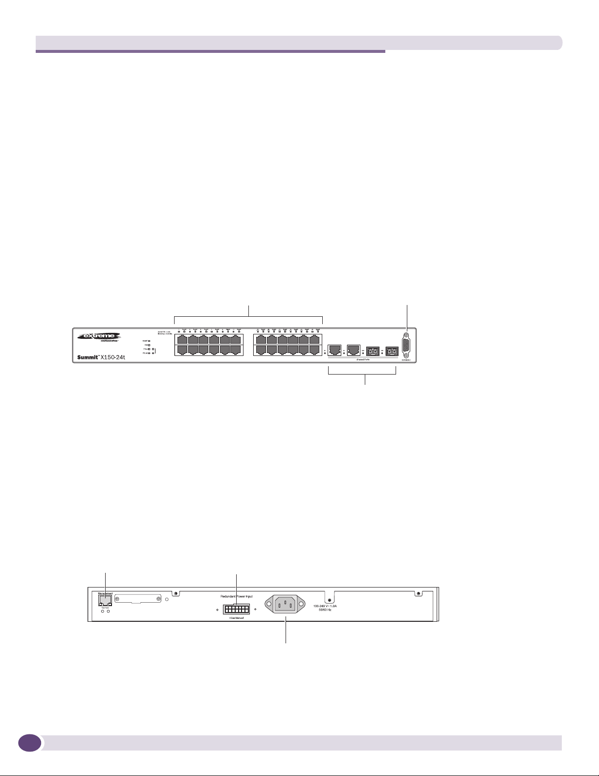
Summit X150-24t Switch
The front panel of the Summit X150-24t switch (Figure 1) includes:
● Twenty-four fixed autosensing 10/100BASE-T ports (ports 1–24) that provide 2.4 Gbps of
high-density copper connectivity
● Two combination ports (ports 25–26) using RJ-45 connectors and SFPs to provide 2 Gbps of copper
or fiber connectivity
For more information about combination ports, see “Combination Ports and Failover” on page 16.
For information about SFPs, see the Extre me Ne two rk s Plug ga b le Inte rfa c e Mod ule s Ins ta lla tio n Guid e .
● LEDs to indicate port status and switch operating conditions.
For a description of the LEDs and their operation, see “Summit X150 Series Switch LEDs” on
page 21.
● Serial console port used to connect a terminal and perform local management.
Figure 1: Summit X150-24t Switch Front Panel
10/100 Mbps ports
Stack
1
2
port
Combination ports
Console
SH_050B
The rear panel of the Summit X150-24t switch (Figure 2) includes:
● Ethernet management port with associated LEDs
● Redundant power input connector for optional connection to the EPS-160 External Power Module.
See “EPS-160 External Power Module (with EPS-T)” on page 75 for more information. The
connecting redundant power supply cable is shipped with the EPS-160 unit.
● AC power input socket
Figure 2: Summit X150-24t Switch Rear Panel
External power
Management port
supply connection
18
Power socket
SH_051
Summit Family Switches Hardware Installation Guide
Page 19

Summit X150-24p Switch
The front panel of the Summit X150-24p switch (Figure 3) includes:
● Twenty-four fixed autosensing 10/100BASE-T PoE ports (ports 1–24). In addition to 4 Gbps of
high-density copper connectivity, these ports also provide a full 15.4 Watts of PoE per port.
● Two combination ports (ports 25–26) using RJ-45 connectors and SFPs to provide 2 Gbps of copper
or fiber connectivity
For more information about combination ports, see “Combination Ports and Failover” on page 16.
For information about SFPs, see the Extre me Ne two rk s Plug ga b le Inte rfa c e Mod ule s Ins ta lla tio n Guid e .
● LEDs to indicate port status and switch operating conditions.
For a description of the LEDs and their operation, see “Summit X150 Series Switch LEDs” on
page 21.
● Serial console port used to connect a terminal and perform local management.
Figure 3: Summit X150-24p Switch Front Panel
10/100 Mbps ports
Combination ports
Console
port
SH_052A
The rear panel of the Summit X150-24p switch includes:
● Ethernet management port with associated LEDs
● Redundant power input connector for use optional connection to the EPS-500 External Power Supply
(Model No. 10911) with full PoE power support.
See “EPS-500 External Power Supply Unit” on page 76 for more information. The connecting
redundant power supply cable is shipped with the EPS-500 unit.
● AC power input socket
Figure 4: Summit X150-24p Switch Rear Panel
External power
Management port
supply connection
Power socket
Summit Family Switches Hardware Installation Guide
SH_053
19
Page 20

Summit Family Switches
Summit X150-48t Switch
The front panel of the Summit X150-48t switch (Figure 5) includes:
● Forty-eight fixed autosensing 10/100BASE-T ports (ports 1–48) that provide 4.8 Gbps of high-density
copper connectivity
● Two combination ports (ports 49–50) using RJ-45 connectors and SFPs to provide 2 Gbps of copper
or fiber connectivity
For more information about combination ports, see “Combination Ports and Failover” on page 16.
For information about SFPs, see the Extre me Ne two rk s Plug ga b le Inte rfa c e Mod ule s Ins ta lla tio n Guid e .
● LEDs to indicate port status and switch operating conditions.
For a description of the LEDs and their operation, see “Summit X150 Series Switch LEDs” on
page 21.
● Serial console port used to connect a terminal and perform local management.
Figure 5: Summit X150-48t Switch Front Panel
10/100 Mbps ports Console
port
Combination ports
SH_054A
The rear panel of the Summit X150-48t switch (Figure 6) includes:
● Management port with associated LEDs
● Redundant power input connector for optional connection to the EPS-160 External Power Module.
See “EPS-160 External Power Module (with EPS-T)” on page 75 for more information. The
connecting redundant power supply cable is shipped with the EPS-160 unit.
● AC power input socket
Figure 6: Summit X150-48t Switch Rear Panel
External power
Management port
supply connection
Power socket
SH_055
20
Summit Family Switches Hardware Installation Guide
Page 21

Summit X150 Series Switch LEDs
Tab le 7 lists the of LEDs on the Summit X150 switches, along with their associated colors and meanings.
.
Table 7: LEDs on the Summit X150 Series Switches
Label or Type Color/State Meaning
Front Panel
MGMT Blinking green (fast) Power-on self-test (POST) in progress.
Steady green POST passed. System is booting image.
Blinking green (slow) Normal operation.
Blinking amber Switch diagnostics are running.
or
System is disabled. POST failed or system overheated.
Off No external power attached.
FAN Steady green Normal operation.
Blinking amber Fan failure. Switch will continue to operate unless it overheats.
Off No power.
PSU-I
(Internal power
supply)
PSU-E
(External power
supply)
Port number
1 – 24 or 1 – 48
Port number
25, 26 or 49, 50
(Shared ports)
Additional Port LED Meanings for PoE Switch: Summit X150-24p
All front-panel ports Steady green Link OK; port is not powered.
Rear Panel
Management Port Right LED:
Steady green Normal operation.
Blinking amber Failure.
Off No power.
Steady green Normal operation.
Blinking amber Failure.
Off No external power attached.
Steady green Link is OK.
Blinking green Port is transmitting packets.
Off Link is not present, or port is disabled.
Steady green Link is OK.
Blinking green Activity.
Off Link is not present, or port is disabled.
Steady amber Link is OK; port is powered; no traffic.
Blinking green Link is OK and transmitting packets; port is not powered.
Blinking amber Link is OK and transmitting packets; port is powered.
Slow blinking amber No link, or disabled port; port is powered.
Alternating amber
and green
Off Port is not powered, has no link, or is disabled.
Steady green
Left LED:
Blinking green
Both LEDs off Link is not present.
Port has a power fault.
Link is OK.
Activity.
Summit Family Switches Hardware Installation Guide
21
Page 22

Summit Family Switches
Summit X250e Series Switches
The Summit X250e series switches provide 24 or 48 Ethernet ports that deliver high-density fast
Ethernet connectivity using fixed 10/100/1000BASE-T ports or installable small form pluggable (SFP)
optical modules. Fixed-port models are available either with or without PoE. Each Summit X250e series
switch has two combination ports that provide 10/100/1000 BASE-T or SFP connectivity for 2 Gbps of
copper or fiber connectivity. A serial console port on the front panel allows you to connect a terminal
and perform local management. An Ethernet management port can be used to connect the system to a
parallel management network for administration. Alternatively, you can use an Ethernet cable to
connect this port directly to a laptop to view and locally manage the switch configurations.
On the back of the switch, two high-speed stacking ports allow you to combine multiple units into a
single SummitStack management entity. The rear panel also provides an AC or DC power input socket
and a redundant power connector. (See specific switch descriptions for more information about the
power options.) The switch automatically adjusts to the supply voltage. The redundant power connector
allows you to connect the switch to the EPS-160, EPS-500, or EPS-150DC external power supply. When a
compatible external power supply is used with the Summit X250e series switch, the internal and
external power supplies are fully fault tolerant and load-sharing. If one power supply fails, the other
power supply will provide sufficient power to operate the switch.
The Summit X250e series switches include the following switches:
● Summit X250e-24t Switch
● Summit X250e-24t-TAA Switch
● Summit X250e-24tDC Switch
● Summit X250e-24tDC-TAA Switch
● Summit X250e-24p Switch
● Summit X250e-24p-TAA Switch
● Summit X250e-24x Switch
● Summit X250e-24x-TAA Switch
● Summit X250e-24xDC Switch
● Summit X250e-24x-TAA Switch
● Summit X250e-48t Switch
● Summit X250e-48t-TAA Switch
● Summit X250e-48tDC Switch
● Summit X250e-48tDC-TAA Switch
● Summit X250e-48p Switch
● Summit X250e-48p-TAA Switch
22
NOTE
In the descriptions that follow, references to a Summit X250e series model number also apply to the equivalent
TAA-compliant switch version.
Summit Family Switches Hardware Installation Guide
Page 23

Summit X250e-24t Switch
The front panel of the Summit X250e-24t switch (Figure 7) includes:
● Twenty-four fixed autosensing 10/100BASE-T ports (ports 1–24) that provide 2.4 Gbps of
high-density copper connectivity
● Two combination ports (ports 25–26) using RJ-45 connectors and SFPs to provide 2 Gbps of copper
or fiber connectivity
For more information about combination ports, see “Combination Ports and Failover” on page 16.
For information about SFPs, see the Extre me Ne two rk s Plug ga b le Inte rfa c e Mod ule s Ins ta lla tio n Guid e .
● LEDs to indicate port status and switch operating conditions.
For a description of the LEDs and their operation, see “Summit X250e Series Switch LEDs” on
page 34.
● Stack number indicator showing the position of this switch in a stacked configuration.
● Serial console port used to connect a terminal and perform local management.
Figure 7: Summit X250e-24t Switch Front Panel
10/100 Mbps ports
Stack
1
2
port
Combination portsStack number indicator
Console
SH_038B
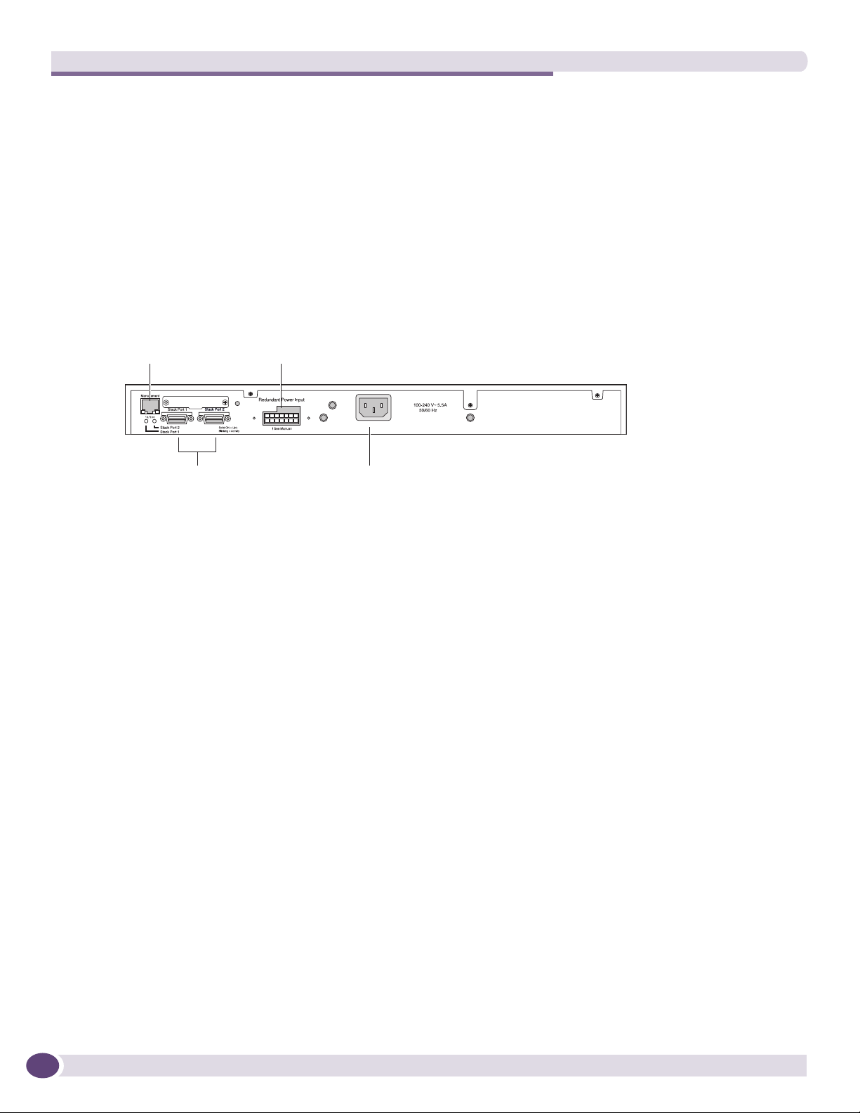
The rear panel of the Summit X250e-24t switch (Figure 8) includes:
● Management port with associated LEDs
● Two high-performance stacking ports with associated LEDs
● Redundant power input connector for optional connection to the EPS-160 External Power Module.
See “EPS-160 External Power Module (with EPS-T)” on page 75 for more information. The
connecting redundant power supply cable is shipped with the EPS-160 unit.
● AC power input socket.
The internal AC power supply operates from 100 VAC to 240 VAC.
Figure 8: Summit X250e-24t Switch Rear Panel
Management port
supply connection
Redundant Power Input
! See Manual
10 Gigabit
stacking ports
Summit Family Switches Hardware Installation Guide
External power
Power socket
SH 039
23
Page 24

Summit Family Switches
Summit X250e-24tDC Switch
The front panel of the Summit X250e-24tDC switch (Figure 33) includes:
● Twenty-four fixed autosensing 10/100BASE-T ports (ports 1–24) that provide 2.4 Gbps of
high-density copper connectivity
● Two combination ports (ports 25–26) using RJ-45 connectors and SFPs to provide 2 Gbps of copper
or fiber connectivity
For more information about combination ports, see “Combination Ports and Failover” on page 16.
For information about SFPs, see the Extre me Ne two rk s Plug ga b le Inte rfa c e Mod ule s Ins ta lla tio n Guid e .
● LEDs to indicate port status and switch operating conditions.
For a description of the LEDs and their operation, see “Summit X250e Series Switch LEDs” on
page 34.
● Stack number indicator showing the position of this switch in a stacked configuration.
● Serial console port used to connect a terminal and perform local management.
Figure 9: Summit X250e-24tDC Switch Front Panel
Console
DC
10/100 Mbps ports
Stack
1
2
port
Combination portsStack number indicator
SH_057_front_x250e-24tdc
The rear panel of the Summit X250e-24tDC switch (Figure 34) includes:
● Ethernet management port with associated LEDs
● Two high-performance stacking ports with associated LEDs
● Redundant power input connector for optional connection to the EPS-150DC External Power Module
(Model No. 10909).
See “EPS-150DC External Power Module (with EPS-T2)” on page 76 for more information. The
connecting redundant power supply cable is shipped with the EPS-150DC unit.
● DC power input socket
The power supply operates from -36 VDC to -72 VDC.
● Grounding lug
24
NOTE
For centralized DC power connection, this product is intended to be installed in a restricted access location (such as
a dedicated equipment room, equipment closet, or central office) in accordance with Articles 110-16, 110-17, and
110-18 of the National Electric Code, ANSI/NFPA 70.
Summit Family Switches Hardware Installation Guide
Page 25

Figure 10: Summit X250e-24tDC Switch Rear Panel
External power
Management port
supply connection
10 Gigabit
stacking ports
Redundant Power Input
! See Manual
DC power
socket
-48 V
1.5 A Max
Grounding
lug
SH_058_rear_x250e-24t-xdc
Summit X250e-24p Switch
The front panel of the Summit X250e-24p switch (Figure 11) includes:
● Twenty-four fixed autosensing 10/100BASE-T PoE ports (ports 1–24). In addition to 2.4 Gbps of
high-density copper connectivity, these ports also provide a full 15.4 Watts of PoE per port.
● Two combination ports (ports 25–26) using RJ-45 connectors and SFPs to provide 2 Gbps of copper
or fiber connectivity
For more information about combination ports, see “Combination Ports and Failover” on page 16.
For information about SFPs, see the Extre me Ne two rk s Plug ga b le Inte rfa c e Mod ule s Ins ta lla tio n Guid e .
● LEDs to indicate port status and switch operating conditions.
For a description of the LEDs and their operation, see “Summit X250e Series Switch LEDs” on
page 34.
● Stack number indicator showing the position of this switch in a stacked configuration.
● Serial console port used to connect a terminal and perform local management.
Figure 11: Summit X250e-24p Switch Front Panel
10/100 Mbps ports
Stack
1
2
Summit Family Switches Hardware Installation Guide
Console
port
Combination portsStack number indicator
SH_040B
25
Page 26
Summit Family Switches
The rear panel of the Summit X250e-24p switch (Figure 12) includes:
● Management port with associated LEDs
● Two high-performance stacking ports with associated LEDs
● Redundant power input connector for use with the EPS-500 External Power Supply (Model No.
10911) with full PoE power support.
See “EPS-500 External Power Supply Unit” on page 76 for more information. The connecting
redundant power supply cable is shipped with the EPS-500 unit.
● AC power input socket.
The internal AC power supply operates from 100 VAC to 240 VAC.
Figure 12: Summit X250e-24p Switch Rear Panel
External power
Management port
supply connection
10 Gigabit
stacking ports
Power socket
SH_041
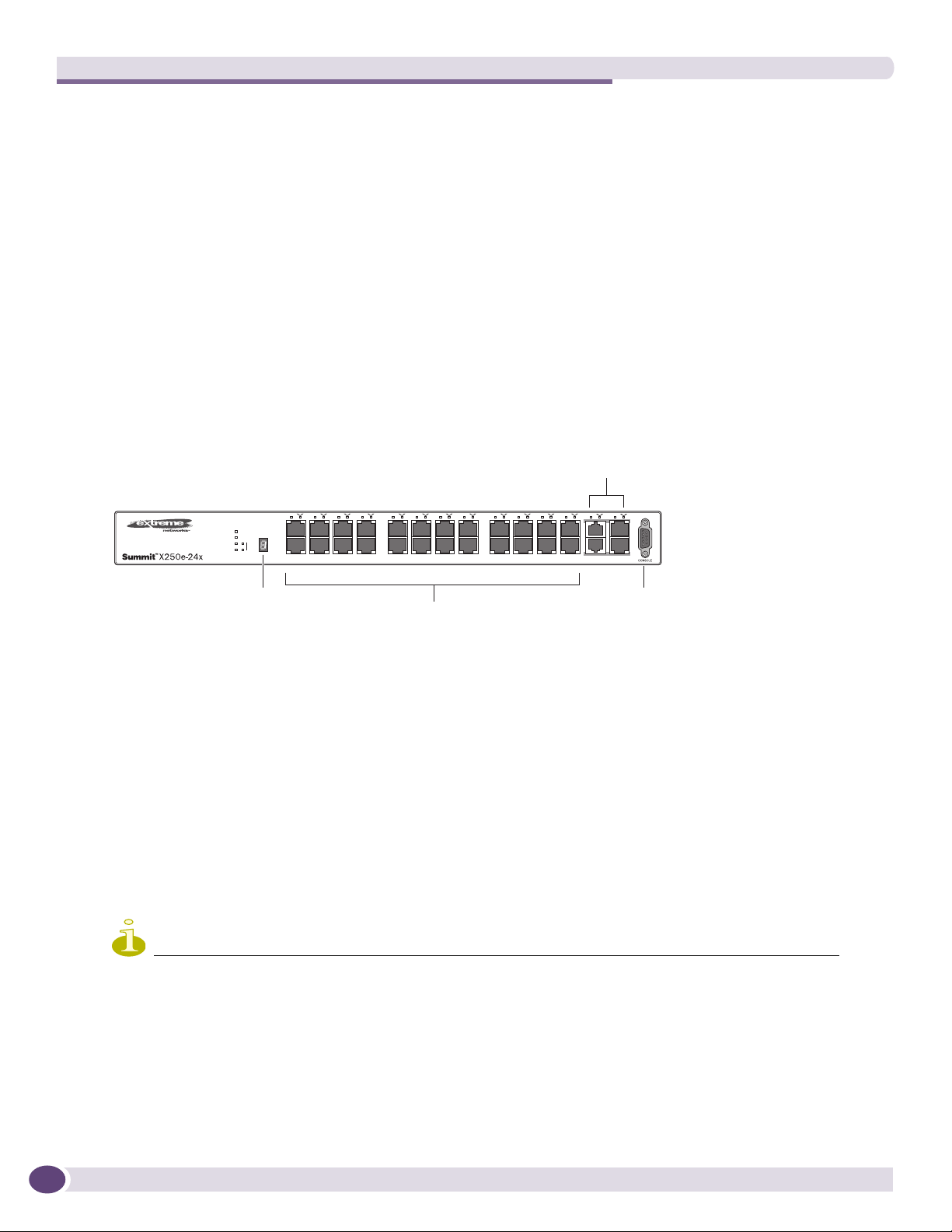
Summit X250e-24x Switch
The front panel of the Summit X250e-24x switch (Figure 7) includes:
● Twenty-four 100BASE-FX ports (ports 1–24) that provide 2.4 Gbps of high-density fiber connectivity
● Two combination ports (ports 25–26) using RJ-45 connectors and SFPs to provide 2 Gbps of copper
or fiber connectivity
For more information about combination ports, see “Combination Ports and Failover” on page 16.
For information about SFPs, see the Extre me Ne two rk s Plug ga b le Inte rfa c e Mod ule s Ins ta lla tio n Guid e .
● LEDs to indicate port status and switch operating conditions.
For a description of the LEDs and their operation, see “Summit X250e Series Switch LEDs” on
page 34.
● Stack number indicator showing the position of this switch in a stacked configuration.
● Serial console port used to connect a terminal and perform local management.
26
Summit Family Switches Hardware Installation Guide
Page 27

Figure 13: Summit X250e-24x Switch Front Panel
Combination ports
Stack number
indicator
100BASE-X ports
Console
port
SH_056A
The rear panel of the Summit X250e-24x switch (Figure 8) includes:
● Management port with associated LEDs
● Two high-performance stacking ports with associated LEDs
● Redundant power input connector for use with the EPS-160 External Power Module.
See “EPS-160 External Power Module (with EPS-T)” on page 75 for more information. The
connecting redundant power supply cable is shipped with the EPS-160 unit.
● AC power input socket.
The internal AC power supply operates from 100 VAC to 240 VAC.
Figure 14: Summit X250e-24x Switch Rear Panel
External power
Management port
10 Gigabit
stacking ports
supply connection
Redundant Power Input
! See Manual
Power socket
SH_039
Summit Family Switches Hardware Installation Guide
27
Page 28
Summit Family Switches
Summit X250e-24xDC Switch
The front panel of the Summit X250e-24xDC switch (Figure 7) includes:
● Twenty-four 100BASE-FX ports (ports 1–24) that provide 2.4 Gbps of high-density fiber connectivity
● Two combination ports (ports 25–26) using RJ-45 connectors and SFPs to provide 2 Gbps of copper
or fiber connectivity
For more information about combination ports, see “Combination Ports and Failover” on page 16.
For information about SFPs, see the Extre me Ne two rk s Plug ga b le Inte rfa c e Mod ule s Ins ta lla tio n Guid e .
● LEDs to indicate port status and switch operating conditions.
For a description of the LEDs and their operation, see “Summit X250e Series Switch LEDs” on
page 34.
● Stack number indicator showing the position of this switch in a stacked configuration.
● Serial console port used to connect a terminal and perform local management.
Figure 15: Summit X250e-24xDC Switch Front Panel
Combination ports
DC
Stack number
indicator
100BASE-X ports
SH_059_front_x250e-24xdc
Console
port
The rear panel of the Summit X250e-24xDC switch (Figure 8) includes:
● Management port with associated LEDs
● Two high-performance stacking ports with associated LEDs
● Redundant power input connector for use with the EPS-150DC External Power Module (Model No.
10909).
See “EPS-150DC External Power Module (with EPS-T2)” on page 76 for more information. The
connecting redundant power supply cable is shipped with the EPS-150DC unit.
● DC power input socket
The power supply operates from -36 VDC to -72 VDC.
● Grounding lug
NOTE
For centralized DC power connection, this product is intended to be installed in a restricted access location (such as
a dedicated equipment room, equipment closet, or central office) in accordance with Articles 110-16, 110-17, and
110-18 of the National Electric Code, ANSI/NFPA 70.
28
Summit Family Switches Hardware Installation Guide
Page 29

Figure 16: Summit X250e-24xDC Switch Rear Panel
External power
Management port
supply connection
10 Gigabit
stacking ports
Redundant Power Input
! See Manual
DC power
socket
-48 V
1.5 A Max
Grounding
lug
SH_058_rear_x250e-24t-xdc
Summit X250e-48t Switch
The front panel of the Summit X250e-48t switch (Figure 17):
● Forty-eight fixed autosensing 10/100BASE-T ports (ports 1–48) that provide 4.8 Gps of high-density
copper connectivity
● Two combination ports (ports 49–50) using RJ-45 connectors and SFPs to provide 2 Gbps of copper
or fiber connectivity
For more information about combination ports, see “Combination Ports and Failover” on page 16.
For information about SFPs, see the Extre me Ne two rk s Plug ga b le Inte rfa c e Mod ule s Ins ta lla tio n Guid e .
● LEDs to indicate port status and switch operating conditions.
For a description of the LEDs and their operation, see “Summit X250e Series Switch LEDs” on
page 34.
● Stack number indicator showing the position of this switch in a stacked configuration.
● Serial console port used to connect a terminal and perform local management.
Figure 17: Summit X250e-48t Switch Front Panel
10/100 Mbps ports Console
Stack number indicator
Summit Family Switches Hardware Installation Guide
port
Combination ports
SH_044B
29
Page 30

Summit Family Switches
The rear panel of the Summit X250e-48t switch (Figure 18) includes:
● Management port with associated LEDs
● Two high-performance stacking ports with associated LEDs
● Redundant power input connector for optional connection to the EPS-160 External Power Module.
See “EPS-160 External Power Module (with EPS-T)” on page 75 for more information. The
connecting redundant power supply cable is shipped with the EPS-160 unit.
● AC power input socket.
The internal AC power supply operates from 100 VAC to 240 VAC.
Figure 18: Summit X250e-48t Switch Rear Panel
External power
Management port
supply connection
Stacking ports
Power socket
SH_045
Summit X250e-48tDC Switch
The front panel of the Summit X250e-48tDC switch (Figure 17):
● Forty-eight fixed autosensing 10/100BASE-T ports (ports 1–48) that provide 4.8 Gps of high-density
copper connectivity
● Two combination ports (ports 49–50) using RJ-45 connectors and SFPs to provide 2 Gbps of copper
or fiber connectivity
For more information about combination ports, see “Combination Ports and Failover” on page 16.
For information about SFPs, see the Extre me Ne two rk s Plug ga b le Inte rfa c e Mod ule s Ins ta lla tio n Guid e .
● LEDs to indicate port status and switch operating conditions.
For a description of the LEDs and their operation, see “Summit X250e Series Switch LEDs” on
page 34.
● Stack number indicator showing the position of this switch in a stacked configuration.
● Serial console port used to connect a terminal and perform local management.
Figure 19: Summit X250e-48tDC Switch Front Panel
30
Stack number indicator
10/100 Mbps ports Console
port
Combination ports
Summit Family Switches Hardware Installation Guide
Page 31

The rear panel of the Summit X250e-48tDC switch (Figure 18) includes:
● Management port with associated LEDs
● Two high-performance stacking ports with associated LEDs
● Redundant power input connector for use with the EPS-150DC External Power Module (Model No.
10909).
See “EPS-150DC External Power Module (with EPS-T2)” on page 76 for more information. The
connecting redundant power supply cable is shipped with the EPS-150DC unit.
● DC power input socket.
The power supply operates from -36 VDC to -72 VDC.
● Grounding lug
NOTE
For centralized DC power connection, this product is intended to be installed in a restricted access location (such as
a dedicated equipment room, equipment closet, or central office) in accordance with Articles 110-16, 110-17, and
110-18 of the National Electric Code, ANSI/NFPA 70.
Figure 20: Summit X250e-48tDC Switch Rear Panel
External power
Management port
10 Gigabit
stacking ports
supply connection
Redundant Power Input
! See Manual
DC power
socket
-48 V
2.0 A Max
SH_063_rear_x250e-48tdc
Summit Family Switches Hardware Installation Guide
31
Page 32

Summit Family Switches
Summit X250e-48p Switch
The front panel of the Summit X250e-48p switch (Figure 21) includes:
● Forty-eight fixed autosensing 10/100BASE-T PoE ports (ports 1–48). In addition to 4.8 Gbps of
high-density copper connectivity, these ports provide a full 15.4 Watts of PoE per port when used
with the EPS-600LS External Power Module.
● Two combination ports (ports 49–50) using RJ-45 connectors and SFPs to provide 2 Gbps of copper
or fiber connectivity
For more information about combination ports, see “Combination Ports and Failover” on page 16.
For information about SFPs, see the Extre me Ne two rk s Plug ga b le Inte rfa c e Mod ule s Ins ta lla tio n Guid e .
● LEDs to indicate port status and switch operating conditions.
For a description of the LEDs and their operation, see “Summit X250e Series Switch LEDs” on
page 34.
● Stack number indicator showing the position of this switch in a stacked configuration.
● Serial console port used to connect a terminal and perform local management.
Figure 21: Summit X250e-48p Switch Front Panel
Stack number indicator
10/100 Mbps ports Console
Combination ports
port
SH_042B
The rear panel of the Summit X250e-48p switch (Figure 22) includes:
● Management port with associated LEDs
● Two high-performance stacking ports with associated LEDs
● Redundant power input connector for use with one or more EPS-600LS External Power Modules
(Model No. 10913) installed in an EPS-C chassis (Model No. 10912).
The PoE capability of the Summit X250e-48p switch varies depending on the number of external
power modules in use. For more information, see “EPS-600LS External Power Module” on page 77.
The connecting redundant power supply cable is shipped with the EPS-C chassis.
● AC power input socket.
The internal AC power supply operates from 100 VAC to 240 VAC.
Figure 22: Summit X250e-48p Switch Rear Panel
Management port
External power
supply connection
32
10 Gigabit
stacking ports
Power socket
Summit Family Switches Hardware Installation Guide
Page 33

Summit X250e-48p Power Supplies
The Summit X250e-48p switch is powered by both an internal power supply and an optional external
redundant power supply system.
Internal Power Supply
The internal Summit X250e-48p internal power supply can provide 370 W of PoE power, as follows:
● In a 24-port configuration, it provides 15.4 W to each port
● In a 48-port configuration or any combination of ports where total PoE power does not exceed 370
watts, it provides 7.7 W to each port.
If the total system demands exceed this power limit, you can specify one of the following:
● Port priorities to identify which ports should be ranked higher when allocating power
● Port disconnect precedence to specify the method of shutting off ports when not enough PoE power
is available
NOTE
For a detailed discussion of these concepts, see the Power over Ethernet section in the ExtremeXOS Concepts
Guide.
External Power Supplies
The EPS-600LS External Power Module provides optional redundant power for the Summit X250e-48p
switch. Through the redundant power input connector on the rear panel, the switch can be powered by
one, two, or three external power modules installed in the EPS-C External Power Supply Chassis.
The PoE capability of the Summit X250e-48p varies depending on the number of external power
modules in use. Tab le 8 summarizes the PoE power behavior for the Summit X250e-48p switch based on
the number of power supply modules in use.
Table 8: Number of External Power Modules and Corresponding PoE Behavior
Internal Power
Supply Status
Internal power
supply:
Power on
Internal power
supply:
Power Failure
EPS-600LS (1x) EPS-600LS (2x) EPS-600LS (3x)
370 W of
redundant power
370 W of
external power only
740 W of
external power only
Internal power supply
disabled
740 W of
external power only
740 W of
external power only
with 2:1 redundancy
Internal power supply
disabled
740 W of
external power only
with 2:1 redundancy
External PSU/Chassis
Failed/Disconnected
370 W of
internal power only
No PoE power
For specifications and installation instructions for the external power module, see “EPS-600LS External
Power Module” on page 77.
Summit Family Switches Hardware Installation Guide
33
Page 34

Summit Family Switches
Summit X250e Series Switch LEDs
Tab le 9 describes the LEDs on the Summit X250e switches.
Table 9: LEDs on the Summit X250e Series Switches
Label or Type Color/State Meaning
Front Panel
MGMT Blinking green (fast) Power-on self-test (POST) in progress
Steady green POST passed. System is booting image.
Blinking green (slow) Normal operation.
Blinking amber Switch diagnostics are running.
or
System is disabled. POST failed or system overheated.
Off No external power attached
FAN Steady green Normal operation
Blinking amber Fan failure. Switch will continue to operate unless it overheats.
Off No power
PSU-I
(Internal power
supply)
PSU-E
(External power
supply)
Port number
1 – 24 or 1 –
48
Port number
25, 26 or 49,
50
(Shared ports)
Stack 1,2 Steady green Link OK on the indicated stack port.
Stack Number
Indicator
Steady green Normal operation
Blinking amber Failure
Off No power
Steady green Normal operation
Blinking amber Failure
Off No external power attached
Steady green Link is OK.
Blinking green Port is transmitting packets.
Off Link is not present, or port is disabled.
Steady green Link is OK
Blinking green Port is transmitting packets.
Off Link is not present, or port is disabled.
Blinking green Activity on the indicated stack port.
Off This switch is not in stacking mode.
Top half of number
blinking
Lower half of number
blinking
Number lights steadily This switch is a standby switch (neither the master nor the
This switch is the stack master.
This switch is the stack backup.
backup).
34
Summit Family Switches Hardware Installation Guide
Page 35

Table 9: LEDs on the Summit X250e Series Switches (Continued)
Label or Type Color/State Meaning
Additional Port LED Meanings for PoE Switches: Summit X250e-24p & Summit X250e-48p
All front-panel
ports
Rear Panel
Management
Port
Stack Port 1,
Stack Port 2
Steady green Link OK. port not powered.
Steady amber Link OK, port is powered, no traffic
Blinking green Link OK, transmitting packets, port not powered.
Blinking amber Link OK, transmitting packets, port is powered.
Slow blinking amber No link or disabled port, port is powered
Alternating amber and
Port has a power fault.
green
Off Port is not powered, has no link, or is disabled.
Right LED: Steady green Link OK
Left LED: Blinking green Activity
Both LEDs off Link is not present.
Steady green Link OK
Blinking green Activity
Off No link
Summit Family Switches Hardware Installation Guide
35
Page 36

Summit Family Switches
Summit X350 Series Switches
The Summit X350 series switches provide 24 or 48 Ethernet ports that deliver high-density fast Ethernet
connectivity using fixed 10/100/1000BASE-T ports. Each Summit X350 series switch has four
combination ports that provide 10/100/1000 BASE-T or SFP connectivity for 2 Gbps of copper or fiber
connectivity. A serial console port on the front panel allows you to connect a terminal and perform local
management. An Ethernet management port can be used to connect the system to a parallel
management network for administration. Alternatively, you can use an Ethernet cable to connect this
port directly to a laptop to view and locally manage the switch configurations.
The rear panel of the switch has an option slot to accommodate one of the following Summit option
cards:
■ Summit XGM2-2xf option card, which allows you to add one or two 10-gigabit XFP modules
■ Summit XGM2-2xn option card, which allows you to add one or two 10-gigabit XFP modules
■ Summit XGM2-2bt option card, which allows you to add one or two fixed 10GBASE-T ports
■ Summit XGM2-2sf option card, which allows you to add one or two 10-gigabit SFP+ modules
For option card installation instructions, see
Chapter 7, “Summit Option Cards.”
Power connectors on the rear panel of the switch include an AC power input socket and a redundant
power connector. The internal AC power supply operates from 100 VAC to 240 VAC. The switch
automatically adjusts to the supply voltage. The redundant power connector allows you to connect the
switch to the EPS-500 external power supply. When a compatible external power supply is used with
the Summit X350 series switch, the internal and external power supplies are fully fault tolerant and
load-sharing. If one power supply fails, the other power supply provides sufficient power to operate the
switch.
The Summit X350 series switches include the following switches:
● Summit X350-24t Switch
● Summit X350-24t-TAA Switch
● Summit X350-48t Switch
● Summit X350-48t-TAA Switch
NOTE
In the descriptions that follow, references to a Summit X350 series model number also apply to the equivalent
TAA-compliant switch version.
36
Summit Family Switches Hardware Installation Guide
Page 37

Summit X350-24t Switch
The front panel of the Summit X350-24t switch (Figure 23) includes:
● Twenty fixed autosensing 10/100/1000BASE-T ports (ports 1–20) that provide 20 Gbps of
high-density copper connectivity
● Four combination ports (ports 21-24) using RJ-45 connectors and SFPs to provide 4 Gbps of copper
or fiber connectivity
For more information about combination ports, see “Combination Ports and Failover” on page 16.
For information about SFPS, see the E xtre me Ne two rks Plug ga b le Inte rfa ce Mo dule s Ins ta lla tio n G uid e .
● LEDs to indicate port status and switch operating conditions.
For a description of the LEDs and their operation, see Tabl e 10 .
● Serial console port used to connect a terminal and perform local management.
Figure 23: Summit X350-24t Switch Front Panel
10/100/1000 Mbps ports
Combination ports
Console
port
SH_064
The rear panel of the Summit X350-24t switch (Figure 24) includes:
● Slot for the one of the following Summit option cards:
■ Summit XGM2-2xf option card, which allows you to add one or two 10-gigabit XFP modules
See “Summit XGM2-2xf Option Card” on page 198.
■ Summit XGM2-2xn option card, which allows you to add one or two 10-gigabit XFP modules
See “Summit XGM2-2xn Option Card” on page 197
■ Summit XGM2-2bt option card, which allows you to add one or two fixed 10GBASE-T ports
See “Summit XGM2-2bt Option Card” on page 199
■ Summit XGM2-2sf option card, which allows you to add one or two 10-gigabit SFP+ modules
See “Summit XGM2-2sf Option Card” on page 199
● Management port with associated LEDs
● Redundant power input connector for optional connection to the EPS-500 External Power Module
(Model No. 10907).
See “EPS-500 External Power Supply Unit” on page 76 for more information. The connecting
redundant power supply cable is shipped with the EPS-500 unit.
● AC power input socket
The power supply operates from 100 VAC to 240 VAC.
Summit Family Switches Hardware Installation Guide
37
Page 38

Summit Family Switches
Figure 24: Summit X350-24t Switch Rear Panel
External power
Management port
supply connection
10 Gigabit
Power socket
uplink option
SH_065_rear_X350_24t
Summit X350-48t Switch
The front panel of the Summit X350-48t switch (Figure 39) includes:
● Forty-four fixed autosensing 10/100/1000 BASE-T ports (ports 1-44) that provide 44 Gbps of
high-density copper connectivity
● Four combination ports (ports 45-48) using RJ-45 connectors and SFPs to provide 4 Gbps of copper
or fiber connectivity
For more information about combination ports, see “Combination Ports and Failover” on page 16.
For information about SFPs, see the Extre me Ne two rk s Plug ga b le Inte rfa c e Mod ule s Ins ta lla tio n Guid e .
● LEDs to indicate port status and switch operating conditions.
For a description of the LEDs and their operation, see “Summit X450, X450a, and X450e Series
Switch LEDs” on page 58.
● Serial console port used to connect a terminal and perform local management.
Figure 25: Summit X350-48t Switch Front Panel
Combination ports
38
21
Stack 10G
121
MGMT
FAN
PSU-1
PSU-E
4365871091211 1413 1615 1817 2019 2221 2423 2625 2827 3029 3231 3433 3635 3837 4039 4241 4443 4645 4847 46X45X 48X47X
2
Shared Ports
Band On = Link
Blinking = Activity
Console
10/100/1000 Mbps ports
port
SH_066
Summit Family Switches Hardware Installation Guide
Page 39

The rear panel of the Summit X350-48t switch (Figure 40) includes:
● Slot for the one of the following Summit option cards:
■ Summit XGM2-2xn option card, which allows you to add one or two 10-gigabit XFP modules
See “Summit XGM2-2xn Option Card” on page 197.
■ Summit XGM2-2xf option card, which allows you to add one or two 10-gigabit XFP modules
See “Summit XGM2-2xf Option Card” on page 198.
■ Summit XGM2-2sf option card, which allows you to add one or two 10-gigabit SFP+ modules
See “Summit XGM2-2sf Option Card” on page 199.
■ Summit XGM2-2bt option card, which allows you to add one or two fixed 10GBASE-T ports
See “Summit XGM2-2bt Option Card” on page 199.
● Management port with associated LEDs
● Redundant power input connector for optional connection to the EPS-500 External Power Supply
Unit (Model No. 10911).
See “EPS-500 External Power Supply Unit” on page 76 for more information. The connecting
redundant power supply cable is shipped with the EPS-500 power supply.
● AC power input socket
The power supply operates from 100 VAC to 240 VAC.
Figure 26: Summit X350-48t Switch Rear Panel
External power
Management port
10 Gigabit
uplink option
supply connection
Power socket
SH_067_rear_X350-48t
Summit Family Switches Hardware Installation Guide
39
Page 40

Summit Family Switches
Summit X350 Series Switch LEDs
Tab le 12 lists the LEDs and their associated colors and meanings.
Table 10: LEDs on the Summit X350 Series Switches
Label or Type Color/State Meaning
Front Panel
MGMT Blinking green (fast) Power-on self-test (POST) in progress
Steady green POST passed. System is booting image.
Blinking green
(slow)
Blinking amber Switch diagnostics are running.
FAN Steady green Normal operation
Blinking amber Failure
Off No power
PSU-I
(Internal power supply)
PSU-E
(External power supply)
Front-panel Port LEDs
Ethernet Ports
1 – 24 or 1 – 48 (21 – 24
and 45 – 48 are shared ports)
Rear Panel
Management Port Steady green Link OK
SFP 1G Port Steady green Link OK
XENPAK 10G Port Steady green Link OK
Steady green Normal operation
Blinking amber Failure
Off No power
Steady green Normal operation
Blinking amber Failure
Off No external power attached
Steady green Link OK
Blinking green Activity
Off Link is not present.
Blinking green Activity
Off Link is not present.
Blinking green Activity
Blinking green Activity
Off Link down
Normal operation.
or
System is disabled. POST failed or system
overheated.
or
Port is disabled.
40
Summit Family Switches Hardware Installation Guide
Page 41

Summit X450, X450a, and X450e Series Switches
The Summit X450 series, Summit X450a series, and Summit X450e series switches provide 24 or 48
Ethernet ports. These switches deliver high-density fast Ethernet connectivity using fixed
10/100/1000BASE-T ports or installable small form pluggable (SFP) optical modules. Models in
different series are available both with and without PoE and in AC or DC power versions.
Each Summit X450, X450a, or X450e series switch has four combination ports that provide 10/100/1000
BASE-T or SFP connectivity for 4 Gbps of copper or fiber connectivity. A serial console port on the front
panel allows you to connect a terminal and perform local management. An Ethernet management port
on the back panel can be used to connect the system to a parallel management network for
administration. Alternatively, you can use an Ethernet cable to connect the Ethernet management port
directly to a laptop to view and locally manage the switch configurations.
The rear panel of the switch has an option slot to accommodate one of the following Summit option
cards:
● Summit XGM-2xn option card, which allows you to add one or two 10-gigabit XENPAK modules
● Summit XGM2-2xn option card, which allows you to add one or two 10-gigabit XENPAK modules
● Summit XGM2-2xf option card, which allows you to add one or two 10-gigabit XFP modules
Option card compatibility depends on the specific switch series. See the individual switch
descriptions for the option card supported on each switch. For option card installation instructions,
see
Chapter 7, “Summit Option Cards.”
Two high-speed stacking ports allow you to combine multiple units into a single SummitStack
management entity. Power connectors include an AC or DC power input socket and a redundant power
connector. (See specific switch descriptions for more information about the power options.) The switch
automatically adjusts to the supply voltage. The redundant power connector allows you to connect the
switch to the an external power supply. When a compatible external power supply is used with the
Summit X450, X450a, or X450e series switch, the internal and external power supplies are fully fault
tolerant. For most switches, if one power supply fails, the other power supply will provide sufficient
power to operate the switch. For information about power supply redundancy with the Summit
X450a-48p switch, see “Summit X450e-48p Power Supplies” on page 57.
For information about each switch series, see the following sections:
● Summit X450 Series Switches on page 42
● Summit X450a Series Switches on page 45
● Summit X450e Series Switches on page 54
Summit Family Switches Hardware Installation Guide
41
Page 42

Summit Family Switches
Summit X450 Series Switches
The Summit X450 series switches are 24-port switches without PoE options. The ports are implemented
as fixed 10/100/1000BASE-t RJ-45 ports or as installable SFP modules. These switches are available only
with AC internal power supplies.
The Summit X450 series of switches consists of the following switches:
● Summit X450-24t Switch
● Summit X450-24x Switch
Summit X450-24t Switch
The front panel of the Summit X450-24t switch (Figure 27) includes:
● Twenty fixed autosensing 10/100/1000BASE-T ports (ports 5-24) that provide 20 Gbps of
high-density copper connectivity
● Four combination ports (ports 1-4) using RJ-45 connectors and SFPs to provide 4 Gbps of copper or
fiber connectivity
For more information about combination ports, see “Combination Ports and Failover” on page 16.
For information about SFPS, see the E xtre me Ne two rks Plug ga b le Inte rfa ce Mo dule s Ins ta lla tio n G uid e .
● LEDs to indicate port status and switch operating conditions.
For a description of the LEDs and their operation, see “Summit X450, X450a, and X450e Series
Switch LEDs” on page 58.
● Stack number indicator showing the position of this switch in a stacked configuration.
● Serial console port used to connect a terminal and perform local management.
Figure 27: Summit X450-24t Switch Front Panel
10/100/1000 Mbps portsMini-GBIC ports
Band On = Link
STACK NO.
Blinking = Activity
Shared Ports
Stack number
indicator
Combination ports
The rear panel of the Summit X450-24t switch (Figure 28) includes:
● Slot for the Summit XGM-2xn option card, which allows you to add one or two 10-gigabit XENPAK
modules
For information about the Summit XGM-2xn option card, see “Summit XGM-2xn Option Card” on
page 196.
● Management port with associated LEDs
● Two high-performance stacking ports with associated LEDs
Console
port
S450_002D
42
Summit Family Switches Hardware Installation Guide
Page 43

● Redundant power input connector for optional connection to the EPS-160 External Power Module
(Model No. 10907).
See “EPS-160 External Power Module (with EPS-T)” on page 75 for more information. The
connecting redundant power supply cable is shipped with the EPS-160 unit.
● AC power input socket
The power supply operates from 100 VAC to 240 VAC.
Figure 28: Summit X450-24t Switch Rear Panel
External power
Management port
supply connection
10 Gigabit
uplink option
10 Gigabit
stacking ports
Power socket
S450_003A
Summit X450-24x Switch
The front panel of the Summit X450-24x switch (Figure 29) includes:
● Twenty fixed SFP ports (ports 5-24) that provide 20 Gbps of high-density fiber connectivity
For information about SFPS, see the E xtre me Ne two rks Plug ga b le Inte rfa ce Mo dule s Ins ta lla tio n G uid e .
● Four combination ports (ports 1-4) using RJ-45 connectors and SFPs to provide 4 Gbps of copper or
fiber connectivity
For more information about combination ports, see “Combination Ports and Failover” on page 16.
For information about SFPs, see the Extre me Ne two rk s Plug ga b le Inte rfa c e Mod ule s Ins ta lla tio n Guid e .
● LEDs to indicate port status and switch operating conditions.
For a description of the LEDs and their operation, see “Summit X450, X450a, and X450e Series
Switch LEDs” on page 58.
● Stack number indicator showing the position of this switch in a stacked configuration.
● Serial console port used to connect a terminal and perform local management.
Figure 29: Summit X450-24x Switch Front Panel
10/100/1000 Mbps ports
Band On = Link
STACK NO.
Blinking = Activity
Shared Ports
Stack number
indicator
Summit Family Switches Hardware Installation Guide
Combination ports
Mini-GBIC ports
Console
port
S450_001D
43
Page 44

Summit Family Switches
The rear panel of the Summit X450-24x switch (Figure 30) includes:
● Slot for the Summit XGM-2xn option card, which allows you to add one or two 10-gigabit XENPAK
modules
For information about the Summit XGM-2xn option card, see
page 196
● Management port with associated LEDs
● Two high-performance stacking ports with associated LEDs
● Redundant power input connector for optional connection to the EPS-160 External Power Module
.
“Summit XGM-2xn Option Card” on
(Model No. 10907).
See “EPS-160 External Power Module (with EPS-T)” on page 75 for more information. The
connecting redundant power supply cable is shipped with the EPS-160 unit.
● AC power input socket
The power supply operates from 100 VAC to 240 VAC.
Figure 30: Summit X450-24x Switch Rear Panel
External power
Management port
supply connection
10 Gigabit
uplink option
10 Gigabit
stacking ports
Power socket
S450_003A
44
Summit Family Switches Hardware Installation Guide
Page 45

Summit X450a Series Switches
The Summit X450a series switches are 24-port or 48-port switches without PoE options. The Ethernet
ports are implemented as fixed 10/100/1000BASE-T RJ-45 ports or as installable SFP modules. These
switches are available with either AC or DC internal power supplies. The switch automatically adjusts
to the supply voltage. The internal AC power supply operates from 100 VAC to 240 VAC. The internal
DC power supply operates from -36 VDC to -72 VDC.
The Summit X450a series switches include the following switches:
● Summit X450a-24t Switch
● Summit X450a-24t-TAA Switch
● Summit X450a-24tDC Switch
● Summit X450a-24tDC-TAA Switch
● Summit X450a-24x Switch
● Summit X450a-24x-TAA Switch
● Summit X450a-24xDC Switch
● Summit X450a-24xDC-TAA Switch
● Summit X450a-48t Switch
● Summit X450a-48t-TAA Switch
● Summit X450a-48tDC Switch
● Summit X450a-48tDC-TAA Switch
NOTE
In the descriptions that follow, references to a Summit X450a series model number also apply to the equivalent
TAA-compliant switch version.
Summit X450a-24t Switch
The front panel of the Summit X450a-24t switch (Figure 31) includes:
● Twenty fixed autosensing 10/100/1000 BASE-T ports (ports 1-20) that provide 20 Gbps of
high-density copper connectivity
● Four combination ports (ports 21-24) using RJ-45 connectors and SFPs to provide 4 Gbps of copper
or fiber connectivity
For more information about combination ports, see “Combination Ports and Failover” on page 16.
For information about SFPs, see the Extre me Ne two rk s Plug ga b le Inte rfa c e Mod ule s Ins ta lla tio n Guid e .
● LEDs to indicate port status and switch operating conditions.
For a description of the LEDs and their operation, see “Summit X450, X450a, and X450e Series
Switch LEDs” on page 58.
● Stack number indicator showing the position of this switch in a stacked configuration.
● Serial console port used to connect a terminal and perform local management.
Summit Family Switches Hardware Installation Guide
45
Page 46

Summit Family Switches
Figure 31: Summit X450a-24t Switch Front Panel
Console
port
SH_018B
Stack number
indicator
10/100/1000 Mbps ports
Combination ports
The rear panel of the Summit X450a-24t switch (Figure 32) includes:
● Slot for one of the following Summit option cards:
■ Summit XGM2-2xn option card, which allows you to add up to two 10-gigabit XENPAK modules
■ Summit XGM2-2xf option card, which allows you to add up to two 10-gigabit XFP modules
For information about these Summit option cards, see “Summit XGM2-2xn Option Card” on
page 197 or “Summit XGM2-2xf Option Card” on page 198.
● Management port with associated LEDs
● Two high-performance stacking ports with associated LEDs
● Redundant power input connector for optional connection to a redundant power supply, either the
EPS-LD External Power Supply Unit (Model No. 45019) or the EPS-500 External Power Supply
(Model 10911). The connecting redundant power supply cable is shipped with the external power
supply.
For more information about the external power supplies, see “EPS-LD External Power Supply Unit”
on page 75 or “EPS-500 External Power Supply Unit” on page 76.
● AC power input socket
The power supply operates from 100 VAC to 240 VAC.
46
Figure 32: Summit X450a-24t Switch Rear Panel
External power
Management port
10 Gigabit
uplink option
supply connection
10 Gigabit
stacking ports
Power socket
SH_028
Summit Family Switches Hardware Installation Guide
Page 47

Summit X450a-24tDC Switch
The front panel of the Summit X450a-24tDC switch (Figure 33) includes:
● Twenty fixed autosensing 10/100/1000 BASE-T ports (ports 1-20) that provide 20 Gbps of
high-density copper connectivity
● Four combination ports (ports 21-24) using RJ-45 connectors and SFPs to provide 4 Gbps of copper
or fiber connectivity
For more information about combination ports, see “Combination Ports and Failover” on page 16.
For information about SFPs, see the Extre me Ne two rk s Plug ga b le Inte rfa c e Mod ule s Ins ta lla tio n Guid e .
● LEDs to indicate port status and switch operating conditions.
For a description of the LEDs and their operation, see “Summit X450, X450a, and X450e Series
Switch LEDs” on page 58.
● Stack number indicator showing the position of this switch in a stacked configuration.
● Serial console port used to connect a terminal and perform local management.
Figure 33: Summit X450a-24tDC Switch Front Panel
10/100/1000 Mbps ports
214365871091211 1413 1615 1817 2019 2221 2423 22X21X 24X23X
Solid ON=Link
10G
MGMT
1
STACK NO.
2
FAN
Stack
1
PSU-1
2
PSU-E
Blinking=Activity
Shared Ports
port
Stack number
Console
indicator
Combination ports
SH_020B
The rear panel of the Summit X450a-24tDC switch (Figure 34) includes:
● Slot for one of the following Summit option cards:
■ Summit XGM2-2xn option card, which allows you to add up to two 10-gigabit XENPAK modules
■ Summit XGM2-2xf option card, which allows you to add up to two 10-gigabit XFP modules
For information about these Summit option cards, see “Summit XGM2-2xn Option Card” on
page 197 or “Summit XGM2-2xf Option Card” on page 198.
● Ethernet management port with associated LEDs
● Two high-performance stacking ports with associated LEDs
● Redundant power input connector for optional connection to the EPS-150DC External Power Module
(Model No. 10909).
See “EPS-150DC External Power Module (with EPS-T2)” on page 76 for more information. The
connecting redundant power supply cable is shipped with the EPS-150DC unit.
● DC power input socket
The power supply operates from -36 VDC to -72 VDC.
● Grounding lug
Summit Family Switches Hardware Installation Guide
47
Page 48

Summit Family Switches
NOTE
For centralized DC power connection, this product is intended to be installed in a restricted access location (such as
a dedicated equipment room, equipment closet, or central office) in accordance with Articles 110-16, 110-17, and
110-18 of the National Electric Code, ANSI/NFPA 70.
Figure 34: Summit X450a-24tDC Switch Rear Panel
External power
Management port
supply connection
-48 V
2.0 A Max
Grounding
lug
10 Gigabit
uplink option
10 Gigabit
stacking ports
DC power
socket
SH_026_rear_X450a-24tdc
Summit X450a-24x Switch
The front panel of the Summit X450a-24x switch (Figure 35) includes:
● Twenty fixed 1000BASE-X ports (ports 1-20) that provide 20 Gbps of high-density fiber (SFP)
connectivity
● Four combination ports (ports 21-24) using RJ-45 connectors and SFPs to provide 4 Gbps of copper
or fiber connectivity
For more information about combination ports, see “Combination Ports and Failover” on page 16.
For information about SFPs, see the Extre me Ne two rk s Plug ga b le Inte rfa c e Mod ule s Ins ta lla tio n Guid e .
● LEDs to indicate port status and switch operating conditions.
For a description of the LEDs and their operation, see “Summit X450, X450a, and X450e Series
Switch LEDs” on page 58.
● Stack number indicator showing the position of this switch in a stacked configuration.
● Serial console port used to connect a terminal and perform local management.
Figure 35: Summit X450a-24x Switch Front Panel
48
Solid ON = Link
Blinking = Activity
10G
1
MGMT
STACK NO.
2
FAN
Stack
1
PSU-1
PSU-E
2
Stack number
indicator
Combination ports
2143658710912111413161518172019222124
1000BASE-X ports
Summit Family Switches Hardware Installation Guide
24X
22X
21X
23
23X
Console
port
SH_033B
Page 49

The rear panel of the Summit X450a-24x switch (Figure 36) includes:
● Slot for one of the following Summit option cards:
■ Summit XGM2-2xn option card, which allows you to add up to two 10-gigabit XENPAK modules
■ Summit XGM2-2xf option card, which allows you to add up to two 10-gigabit XFP modules
For information about these Summit option cards, see “Summit XGM2-2xn Option Card” on
page 197 or “Summit XGM2-2xf Option Card” on page 198.
● Management port with associated LEDs
● Two high-performance stacking ports with associated LEDs
● Redundant power input connector for optional connection to an external redundant power supply,
either the EPS-LD External Power Supply Unit (Model No. 45019) or the EPS-500 External Power
Supply (Model 10911). The connecting redundant power supply cable is shipped with the external
power supply.
For more information about the external power supplies, see “EPS-LD External Power Supply Unit”
on page 75 or “EPS-500 External Power Supply Unit” on page 76.
● AC power input socket
The power supply operates from 100 VAC to 240 VAC.
Figure 36: Summit X450a-24x Switch Rear Panel
External power
Management port
10 Gigabit
uplink option
supply connection
10 Gigabit
stacking ports
Power socket
SH_031
Summit Family Switches Hardware Installation Guide
49
Page 50

Summit Family Switches
Summit X450a-24xDC Switch
The front panel of the Summit X450a-24xDC switch (Figure 37) includes:
● Twenty fixed autosensing 1000BASE-X ports (ports 1-20) that provide 20 Gbps of high-density fiber
(SFP) connectivity
● Four combination ports (ports 21-24). using RJ-45 connectors and SFPs to provide 4 Gbps of copper
or fiber connectivity
For more information about combination ports, see “Combination Ports and Failover” on page 16.
For information about SFPs, see the Extre me Ne two rk s Plug ga b le Inte rfa c e Mod ule s Ins ta lla tio n Guid e .
● LEDs to indicate port status and switch operating conditions.
For a description of the LEDs and their operation, see “Summit X450, X450a, and X450e Series
Switch LEDs” on page 58.
● Stack number indicator showing the position of this switch in a stacked configuration.
● Serial console port used to connect a terminal and perform local management.
Figure 37: Summit X450a-24xDC Switch Front Panel
Shared ports
24X
Solid ON = Link
Blinking = Activity
10G
1
MGMT
STACK NO.
2
FAN
Stack
1
PSU-1
PSU-E
2
Stack number
indicator
2143658710912111413161518172019222124
1000BASE-X ports
22X
23
21X
23X
Console
port
SH_034A
The rear panel of the Summit X450a-24xDC switch (Figure 38) includes:
● Slot for one of the following Summit option cards
■ Summit XGM2-2xn option card, which allows you to add up to two 10-gigabit XENPAK modules
■ Summit XGM2-2xf option card, which allows you to add up to two 10-gigabit XFP modules
For information about these Summit option cards, see “Summit XGM2-2xn Option Card” on
page 197 or “Summit XGM2-2xf Option Card” on page 198.
● Management port with associated LEDs
● Two high-performance stacking ports with associated LEDs
● Redundant power input connector for optional connection to the EPS-150DC External Power Module
(Model No. 10909). The connecting redundant power supply cable is shipped with the EPS-150DC
unit.
See “EPS-150DC External Power Module (with EPS-T2)” on page 76 for more information.
● DC power input socket
The power supply operates from -36V DC to -72 V DC.
● Grounding lug
50
Summit Family Switches Hardware Installation Guide
Page 51

c
NOTE
For centralized DC power connection, this product is intended to be installed in a restricted access location (such as
a dedicated equipment room, equipment closet, or central office) in accordance with Articles 110-16, 110-17, and
110-18 of the National Electric Code, ANSI/NFPA 70.
Figure 38: Summit X450a-24xDC Switch Rear Panel
External power
Management port
supply connection
-48 V
2.5 A Max
Grounding
lug
10 Gigabit
uplink option
10 Gigabit
stacking ports
DC power
socket
SH_032_X450a-24xd
Summit X450a-48t Switch
The front panel of the Summit X450a-48t switch (Figure 39) includes:
● Forty-four fixed autosensing 10/100/1000 BASE-T ports (ports 1-44) that provide 44 Gbps of
high-density copper connectivity
● Four combination ports (ports 45-48) using RJ-45 connectors and SFPs to provide 4 Gbps of fiber or
copper connectivity
For more information about combination ports, see “Combination Ports and Failover” on page 16.
For information about SFPs, see the Extre me Ne two rk s Plug ga b le Inte rfa c e Mod ule s Ins ta lla tio n Guid e .
● LEDs to indicate port status and switch operating conditions.
For a description of the LEDs and their operation, see “Summit X450, X450a, and X450e Series
Switch LEDs” on page 58.
● Stack number indicator showing the position of this switch in a stacked configuration.
● Serial console port used to connect a terminal and perform local management.
Figure 39: Summit X450a-48t Switch Front Panel
21
Stack 10G
121
MGMT
STACK NO.
FAN
PSU-1
PSU-E
4365871091211 1413 1615 1817 2019 2221 2423 2625 2827 3029 3231 3433 3635 3837 4039 4241 4443 4645 4847 46X45X 48X47X
2
Summit Family Switches Hardware Installation Guide
Combination ports
Shared Ports
Band On = Link
Blinking = Activity
SH_016C
51
Page 52

Summit Family Switches
The rear panel of the Summit X450a-48t switch (Figure 40) includes:
● Slot for one of the following Summit option cards
■ Summit XGM2-2xn option card, which allows you to add up to two 10-gigabit XENPAK modules
■ Summit XGM2-2xf option card, which allows you to add up to two 10-gigabit XFP modules
For information about these Summit option cards, see “Summit XGM2-2xn Option Card” on
page 197 or “Summit XGM2-2xf Option Card” on page 198.
● Management port with associated LEDs
● Two high-performance stacking ports with associated LEDs
● Redundant power input connector for optional connection to the EPS-500 External Power Supply
Unit (Model No. 10911). The connecting redundant power supply cable is shipped with the EPS-500
power supply.
See “EPS-500 External Power Supply Unit” on page 76 for more information.
● AC power input socket
The power supply operates from 100 VAC to 240 VAC.
Figure 40: Summit X450a-48t Switch Rear Panel
External power
Management port
10 Gigabit
uplink option
supply connection
10 Gigabit
stacking ports
Power socket
SH_029
Summit X450a-48tDC Switch
The front panel of the Summit X450a-48tDC switch (Figure 39) includes:
● Forty-four fixed autosensing 10/100/1000 BASE-T ports (ports 1-44) that provide 44 Gbps of
high-density copper connectivity
● Four combination ports (ports 45-48) using RJ-45 connectors and SFPs to provide 4 Gbps of copper
or fiber connectivity
For more information about combination ports, see “Combination Ports and Failover” on page 16.
For information about SFPs, see the Extre me Ne two rk s Plug ga b le Inte rfa c e Mod ule s Ins ta lla tio n Guid e .
● LEDs to indicate port status and switch operating conditions.
For a description of the LEDs and their operation, see “Summit X450, X450a, and X450e Series
Switch LEDs” on page 58.
● Stack number indicator showing the position of this switch in a stacked configuration.
● Serial console port used to connect a terminal and perform local management.
52
Summit Family Switches Hardware Installation Guide
Page 53

Figure 41: Summit X450a-48tDC Switch Front Panel
Stack number
Combination ports
indicator
21
Stack 10G
121
MGMT
STACK NO.
FAN
PSU-1
PSU-E
4365871091211 1413 1615 1817 2019 2221 2423 2625 2827 3029 3231 3433 3635 3837 4039 4241 4443 4645 4847 46X45X 48X47X
2
Shared Ports
Band On = Link
Blinking = Activity
SH_016D
The rear panel of the Summit X450a-48tDC switch (Figure 40) includes:
● Slot for one of the following Summit option cards:
■ Summit XGM2-2xn option card, which allows you to add up to two 10-gigabit XENPAK modules
■ Summit XGM2-2xf option card, which allows you to add up to two 10-gigabit XFP modules
For information regarding these compatible Summit option cards, see “Summit XGM2-2xn Option
Card” on page 197 or “Summit XGM2-2xf Option Card” on page 198.
● Management port with associated LEDs
● Two high-performance stacking ports with associated LEDs
● Redundant power input connector for optional connection to the EPS-150DC External Power Module
(Model No. 10909). The connecting redundant power supply cable is shipped with the EPS-150DC
unit.
See “EPS-500 External Power Supply Unit” on page 76 for more information.
● DC power input socket
The power supply operates from -36V DC to -72 V DC.
● Grounding lug
NOTE
For centralized DC power connection, this product is intended to be installed in a restricted access location (such as
a dedicated equipment room, equipment closet, or central office) in accordance with Articles 110-16, 110-17, and
110-18 of the National Electric Code, ANSI/NFPA 70.
Figure 42: Summit X450a-48tDC Switch Rear Panel
External power
Management port
Grounding
lug
10 Gigabit
uplink option
10 Gigabit
stacking ports
Summit Family Switches Hardware Installation Guide
supply connection
DC power
socket
-48 V
4.5 A Max
SH_034brear48t
53
Page 54

Summit Family Switches
Summit X450e Series Switches
The Summit X450e series switches are 24-port or 48-port PoE-capable switches. The Ethernet ports are
implemented as fixed 10/100/1000BASE-T RJ-45 ports. These switches are available only with AC
internal power supplies.
The Summit X450e series of switches consists of the following switches:
● Summit X450e-24p Switch
● Summit X450e-24p-TAA Switch
● Summit X450e-48p Switch
● Summit X450e-48p-TAA Switch
NOTE
In the descriptions that follow, references to a Summit X450e series model number also apply to the equivalent
TAA-compliant switch version
Summit X450e-24p Switch
.
The front panel of the Summit X450e-24p switch (Figure 43) includes:
● Twenty fixed autosensing 10/100/1000 BASE-T PoE ports (ports 1-20) that provide high-density
copper connectivity and a full 15.4 Watts of PoE per port
● Four combination ports (ports 21-24) using RJ-45 connectors and SFPs to provide 4 Gbps of copper
or fiber connectivity
For more information about combination ports, see “Combination Ports and Failover” on page 16.
For information about SFPs, see the Extre me Ne two rk s Plug ga b le Inte rfa c e Mod ule s Ins ta lla tio n Guid e .
NOTE
All 24 ports can provide PoE power.
● LEDs to indicate port status and switch operating conditions.
For a description of the LEDs and their operation, see “Summit X450, X450a, and X450e Series
Switch LEDs” on page 58.
● Stack number indicator showing the position of this switch in a stacked configuration.
● Serial console port used to connect a terminal and perform local management.
Figure 43: Summit X450e-24p Switch Front Panel
10/100/1000 Mbps PoE ports
Console
port
54
PORTS 1 -24
POWERED (AMBER) ON=LINK
FLASHING=ACTIVITY
OFF=NO LINK/DISABLED
ALTERNATE AMBER/GREEN=PWR FAULT
10G
MGMT
1
STACK NO.
FAN
2
Stack
PSU-1
1
PSU-E
2
Stack number
indicator
NO POWER (GREEN) ON=LINK
FLASHING=ACTIVITY
OFF=NO LINK/DISABLED
214365871091211 1413 1615 1817 2019 2221 2423 22X21X 24X23X
Shared Ports
Combination ports
SH_015B
Summit Family Switches Hardware Installation Guide
Page 55

The rear panel of the Summit X450e-24p switch (Figure 44) includes:
● Slot for one of the following Summit option cards:
■ Summit XGM2-2xn option card, which allows you to add up to two 10-gigabit XENPAK modules
■ Summit XGM2-2xf option card, which allows you to add up to two 10-gigabit XFP modules
For information about these Summit option cards, see “Summit XGM2-2xn Option Card” on
page 197 or “Summit XGM2-2xf Option Card” on page 198.
● Management port with associated LEDs
● Two high-performance stacking ports with associated LEDs
● Redundant power input connector for optional connection to an external redundant power supply
with full PoE power support, either the EPS-LD External Power Supply Unit (Model 45019) or the
EPS-500 External Power Supply (Model 10911). The connecting redundant power supply cable is
shipped with the power supply.
See “EPS-LD External Power Supply Unit” on page 75 or “EPS-500 External Power Supply Unit” on
page 76 for more information.
● AC power input socket
The power supply operates from 100 VAC to 240 VAC.
Figure 44: Summit X450e-24p Switch Rear Panel
External power
Management port
10 Gigabit
uplink option
supply connection
10 Gigabit
stacking ports
Power socket
SH_027
Summit Family Switches Hardware Installation Guide
55
Page 56

Summit Family Switches
Summit X450e-48p Switch
The front panel of the Summit X450e-48p switch (Figure 45) includes:
● Forty-four fixed autosensing 10/100/1000 BASE-T PoE ports (ports 1-44) that provide high-density
copper connectivity and a full 15.4 Watts of PoE per port when used with the EPS-C/EPS-600LS
● Four combination ports (ports 45-48) using RJ-45 connectors and SFPs to provide 4 Gbps of copper
or fiber connectivity
For more information about combination ports, see “Combination Ports and Failover” on page 16.
For information about SFPs, see the Extre me Ne two rk s Plug ga b le Inte rfa c e Mod ule s Ins ta lla tio n Guid e .
NOTE
All 48 ports can provide PoE power
● LEDs to indicate port status and switch operating conditions.
For a description of the LEDs and their operation, see “Summit X450, X450a, and X450e Series
Switch LEDs” on page 58.
● Stack number indicator showing the position of this switch in a stacked configuration.
● Serial console port used to connect a terminal and perform local management.
Figure 45: Summit X450e-48p Switch Front Panel
Combination ports
46X
Shared Ports
45X
48X
Solid ON = Link
47X
Blinking = Activity
Console
port
2
Stack
10G
121
2
MGMT
STACK NO.
FAN
PSU-1
PSU-E
Stack number
43658710912111413161518172019222124232625282730293231343336353837403942414443 4645 48
1
10/100/1000 Mbps ports
47
indicator
The rear panel of the Summit X450e-48p switch (Figure 46) includes:
● Slot for one of the following Summit option cards:
■ Summit XGM2-2xn option card, which allows you to add up to two 10-gigabit XENPAK modules
■ Summit XGM2-2xf option card, which allows you to add up to two 10-gigabit XFP modules
For information about these Summit option cards, see “Summit XGM2-2xn Option Card” on
page 197 or “Summit XGM2-2xf Option Card” on page 198.
● Management port with associated LEDs
● Two high-performance stacking ports with associated LEDs
● Redundant power input connector for optional connection to the EPS-C chassis (Model No. 10912).
This chassis can hold up to three EPS-600LS External Power Modules (Model No. 10913). The
connecting redundant power supply cable is shipped with the EPS-C chassis.
The PoE capability of the Summit X450e-48p switch varies depending on the number of external
power modules in use. For more information, see “Summit X450e-48p Power Supplies” on page 57
and “EPS-600LS External Power Module” on page 77.
● AC power input socket
The power supply operates from 100 VAC to 240 VAC.
56
Summit Family Switches Hardware Installation Guide
Page 57

Figure 46: Summit X450e-48p Switch Rear Panel
Management port
10 Gigabit
uplink option
10 Gigabit
stacking ports
External power
supply connection
Power socket
SH_033
Summit X450e-48p Power Supplies
The Summit X450e-48p switch is powered by both an internal power supply and an optional external
redundant power supply system.
Internal Power Supply. The internal Summit X450e-48p power supply can provide 370 W of PoE power,
as follows:
● In a 24 port configuration, it provides 15.4 W to each port.
● In 48-port configuration or any combination of ports where total PoE power does not exceed 370
watts, it provides 7.7 W to each port.
If the total system demands exceed this power limit, you can specify:
● Port priorities to identify which ports should be ranked higher when allocating power.
● Port disconnect precedence to specify the method of shutting off ports when not enough PoE power
is available.
NOTE
For a detailed discussion of these concepts, see the Power over Ethernet section in the ExtremeXOS Concepts
Guide.
External Power Supplies. The Summit X450e-48p switch can be powered by one, two, or three external
power modules through the redundant power input connector on the rear of the switch.
The EPS-C (External Power Supply Chassis) is shipped with the redundant power supply cable that
connects to the redundant input connector on the rear of the switch. The EPS-C chassis can hold from
one to three 600-Watt EPS-600LS (external power module) units.
The PoE capability of the Summit X450e-48p switch varies depending on the number of external power
modules in use. Tab le 1 1 summarizes the PoE power behavior for the Summit X450e-48p switch based
on the number of power supply modules in use.
Summit Family Switches Hardware Installation Guide
57
Page 58

Summit Family Switches
Table 11: Number of External PSUs and Corresponding PoE Behavior
Internal PSU
Status
Internal PSU:
Power On
Internal PSU:
Power Failure
EPS-600LS (1x) EPS-600LS (2x) EPS-600LS (3x)
370 W of
redundant power
370 W of
external power only
740 W of
external power only
Internal PSU disabled
740 W of
external power only
740 W of
external power only
with 2:1 redundancy
Internal PSU disabled
740 W of
external power only
with 2:1 redundancy
External PSU/Chassis
Failed/Disconnected
370 W of
internal power only
No PoE power
For more information, see “EPS-600LS External Power Module” on page 77.
Summit X450, X450a, and X450e Series Switch LEDs
Tab le 12 describes the LEDs for the Summit X450, X450a, and X450e switches.
Table 12: LEDs on the Summit X450, X450a, and X450e Switches
Label or Type Color/State Meaning
Front Panel
MGMT Blinking green (fast) Power-on self-test (POST) in progress.
Steady green POST passed. System is booting image.
Blinking green (slow) Normal operation
Blinking amber Switch diagnostics running.
or
System is disabled. POST failed or
system overheated.
Off No external power attached
FAN Steady green Normal operation
Steady amber* A single fan in the array has failed. The
switch can continue to operate
indefinitely.*
Blinking amber Failure
or
Two or more fans in the array have
failed. Because system cooling is
compromised, you should replace the
switch.*
Off No power
* These states for the Fan LED occur only on Summit X450a-48tDC
switches with a manufacturing part number of 800294-00 and
X450a-48tDC-TAA switches with a manufacturing part number of
800337-00.
PSU-I
(Internal power supply)
Steady green Normal operation
Blinking amber Failure
Off No power
58
Summit Family Switches Hardware Installation Guide
Page 59

Table 12: LEDs on the Summit X450, X450a, and X450e Switches (Continued)
Label or Type Color/State Meaning
PSU-E
(External power supply)
Ethernet Ports
1 – 24 or 1 – 48 (21 –24 and
45 – 48 are shared ports)
Stack Number Indicator Top half of number
Additional Port LED meanings for PoE switches: Summit X450e-24p & Summit X450e-48p
All front-panel ports Steady amber Port is powered with link, no traffic
Rear Panel
Management Port Steady green Link OK
Stacking Port Steady green Link OK
SFP 1G Port Steady green Link OK
XENPAK 10G Port Steady green Link OK
Steady green Normal operation
Blinking amber Failure
Off No external power attached
Steady green Link OK
Blinking green Activity
Off Link is not present or port is disabled.
This switch is the stack master.
blinking
Lower half of number
This switch is the stack backup.
blinking
Number lights steadily This switch is a standby node (neither
the master nor the backup).
LED dark This stackable switch is not in stacking
mode.
Blinking amber Port is powered with link, traffic
Slow blinking amber Port is powered, with no link
Alternating amber and
Port is faulted
green
Off Port is not powered, no link or disabled
Blinking green Activity
Blinking green Activity
Blinking green Activity
Blinking green Activity
Off Link down
Summit Family Switches Hardware Installation Guide
59
Page 60

Summit Family Switches
Summit X480 Series Switches
The Summit X480 series switches are 24-port or 48-port switches that provide Ethernet connectivity
using fixed 10/100/1000BASE-T RJ-45 ports, installable SFP optical modules, or installable XFP
optical modules.
The Summit X480 series switches include the following base models:
● Summit X480-24x switch (see page 61)
● Summit X480-48x switch (see page 62)
● Summit X480-48t switch (see page 63)
A serial console port on the front panel of the Summit X480 series switch allows you to connect a
terminal and perform local management. An Ethernet management port can be used to connect the
system to a parallel management network for administration. Alternatively, you can use an Ethernet
cable to connect this port directly to a laptop to view and locally manage the switch configuration.
The Ethernet management port supports 10/100/1000 Mbps speeds.
The rear panel of the switch provides a slot for an installed option card called a versatile interface
module or VIM. The types of VIM available for the Summit X480 series switches are:
● VIM2-SummitStack versatile interface module (see page 64)
Provides two 20-Gbps stacking ports
● VIM2-10G4X versatile interface module (see page 64)
Provides four 10-Gbps XFP ports
● VIM2-SummitStack128 versatile interface module (see page 65)
Provides two 64-Gbps stacking ports
NOTE
The Summit X480 switches are only compatible with VIM2 modules. Other VIM types that may appear to be
mechanically compatible with the Summit X480 switches will not function if they are installed in these switches.
Cooling is provided by a replaceable fan module. Two power supply bays accommodate either AC or
DC power supplies.
60
Summit Family Switches Hardware Installation Guide
Page 61

Summit X480-24x Switch
The front panel of the Summit X480-24x switch (Figure 47) includes:
● Twelve autosensing 100/1000BASE-X ports (ports 1 through 12) that provide 12 Gbps of high-density
fiber (SFP) connectivity
● Twelve combination ports (ports 13 through 24) using RJ-45 connectors or SFPs to provide 12 Gbps
of copper or fiber connectivity. The SFP ports support both 100BASE-X and 1000BASE-X optical
modules.
For more information about combination ports, see “Combination Ports and Failover” on page 16.
For information about SFPs, see the Extre me Ne two rk s Plug ga b le Inte rfa c e Mod ule s Ins ta lla tio n Guid e .
● Two unpopulated 10-Gbps XFP-based ports
● 10/100/1000 Mbps management port
● Console port
● LEDs to indicate port status and switch operating conditions.
For a description of the LEDs and their operation, see “Summit X480 Series Switch LEDs” on
page 66.
● Stack number indicator
Figure 47: Summit X480-24x Switch Front Panel
Combination ports
Stack number
indicator
SFP ports
Management port
10/100/1000
Mbps ports
XFP ports
The rear panel of the Summit X480-24x switch (Figure 48) includes:
● Slot for a virtual interface module (VIM)
● Two power supply bays for either AC or DC power supplies
● Replaceable fan tray
Figure 48: Summit X480-24t Rear Panel
Slot for VIM2
versatile interface module
Fan tray
Two power supply
(PSU) slots
Console port
SH_120
Summit Family Switches Hardware Installation Guide
SH_154
61
Page 62

Summit Family Switches
Summit X480-48x Switch
The front panel of the Summit X480-48x switch (Figure 49) includes:
● Forty-eight 100/1000BASE-X SFP ports that provide 48 Gbps of high-density fiber connectivity
For information about SFPs, see the Extre me Ne two rk s Plug ga b le Inte rfa c e Mod ule s Ins ta lla tio n Guid e .
● 10/100/1000 Mbps management port
● Console port
● LEDs to indicate port status and switch operating conditions.
For a description of the LEDs and their operation, see “Summit X480 Series Switch LEDs” on
page 66.
● Stack number indicator
Figure 49: Summit X480-48x Switch Front Panel
SFP ports
Management port
Stack number
indicator
The rear panel of the Summit X480-48x switch (Figure 50) includes:
● Slot for a virtual interface module (VIM)
● Two power supply bays for either AC or DC power supplies
● Replaceable fan tray
Figure 50: Summit X480-48x Rear Panel
Slot for VIM2
versatile interface module
Fan tray
Two power supply
(PSU) slots
Console
port
SH_118
SH_154
62
Summit Family Switches Hardware Installation Guide
Page 63

Summit X480-48t Switch
The front panel of the Summit X480-48t switch (Figure 51) includes:
● Forty-four fixed 10/100/1000BASE-T autosensing ports (ports 1-44) that provide 44 Gbps of
high-density copper connectivity
● Four combination ports (ports 45-48) using RJ-45 connectors or SFPs to provide 4 Gbps of copper or
fiber connectivity. The SFP ports support both 100BASE-X and 1000BASE-X optical modules.
For more information about combination ports, see “Combination Ports and Failover” on page 16.
For information about SFPs, see the Extre me Ne two rk s Plug ga b le Inte rfa c e Mod ule s Ins ta lla tio n Guid e .
● 10/100/1000 Mbps management port
● Console port
● LEDs to indicate port status and switch operating conditions.
For a description of the LEDs and their operation, see “Summit X480 Series Switch LEDs” on
page 66.
● Stack number indicator
Figure 51: Summit X480-48t Switch Front Panel
10/100/1000 Mbps ports
Management port
Stack number
indicator
The rear panel of the Summit X480-48t switch (Figure 52) includes:
● Slot for a virtual interface module (VIM)
● Two power supply bays for either AC or DC power supplies
● Replaceable fan tray
Figure 52: Summit X480-48t Rear Panel
Slot for VIM2
versatile interface module
Fan tray
Two power supply
(PSU) slots
Console
port
Combination ports
SH_119
Summit Family Switches Hardware Installation Guide
SH_154
63
Page 64

Summit Family Switches
VIM2-SummitStack Versatile Interface Module
The VIM2-SummitStack module (Figure 53) provides two high-performance stacking ports that allow
you to combine multiple units into a single SummitStack management entity.
For more information about configuring and operating a SummitStack configuration, refer to the
ExtremeXOS Concepts Guide and the Extreme XOS Co mma nd Re fe renc e Guide .
Figure 53: VIM2-SummitStack Versatile Interface Module
LED Stacking port
SH_151
VIM2-10G4X Versatile Interface Module
The VIM2-10G4X versatile interface module (Figure 54) provides four 10-Gbps ports using XFP optical
modules. For information about the supported optical modules, refer to the most recent version of the
ExtremeXOS Release Notes.
Figure 54: VIM2-10G4X Versatile Interface Module
XFP ports
S1 S3
S2
LEDs
The XFP ports are labelled S1, S2, S3, and S4. ExtremeXOS software assigns port numbers to the XFP
ports based on the switch model in which the VIM2-10G4X module is installed (see Tab le 1 3).
S4
SH_152
64
Table 13: Port Numbers for XFP Ports on the VIM2-10G4X Module
Port
Label
S1 49 27
S2 50 28
S3 51 29
S4 51 30
Summit X480-48t or
Summit X480-48x
Port Number
Summit X480-24t
Port Number
Summit Family Switches Hardware Installation Guide
Page 65

VIM2-SummitStack128 Versatile Interface Module
The VIM2-SummitStack128 versatile interface module (Figure 55) provides two 64-Gbps SummitStack
stacking ports. To connect these ports, you must use stacking cables with compatible connectors,
available from Extreme Networks.
Figure 55: VIM2-SummitStack128 Versatile Interface Module
LEDsStack port 1 Stack port 2
SH_153
Summit Family Switches Hardware Installation Guide
65
Page 66

Summit Family Switches
Summit X480 Series Switch LEDs
Tab le 14 describes the LEDs on the Summit X480 series switches.
Table 14: LEDs on the Summit X480 Series Switches
Label or Type Color/State Meaning
Front Panel LEDs
MGMT Blinking Green Normal operation
Blinking Amber Power-on self test (POST) failed; diagnostic test in
progress
Off No external power attached
FAN Steady Green Normal operation
Blinking Amber Failure
Off No power
PSU-1 Steady Green Normal operation
Blinking Amber Failure
Off No power
PSU-2 Steady Green Normal operation
Blinking Amber Failure
Off No power
Stack Management 1 – 4 Steady green Link OK on the indicated stack port.
Blinking green Activity on the indicated stack port.
2-digit Stack number Indicator
Left digit (1) Blinking This switch is the stack master node (see description of
right digit).
Off This switch is the stack backup node.
Right digit (1 – 8)
Indicates the position of
this switch in the
SummitStack configuration.
Ethernet Ports
1 – 24 or 1 – 48
Management Port Steady Green Link OK
Back Panel
Stacking Port LED
(on installed VIM)
XFP Port LED
(on installed VIM)
Power Supply LEDs
Top Steady Green +3.3VSB ok; 12 V ok; PSU is working properly.
Middle Steady Amber Fault condition (for example, 3.3VSB OCP/UCP, 12V
Bottom Steady Green PSU is connected to power. If the cord is connected
Upper half blinking This switch is the stack master node.
Lower half blinking This switch is the stack backup node.
Lit steadily This switch is a standby node in the stack.
Steady Green Link OK
Blinking Green Activity
Blinking Green Activity
Steady Green Link OK
Blinking Green Activity
Steady Green Link OK
Blinking Green Activity
OCP/UCP, or fan failure).
and this LED is off, the PSU is defective.
66
Summit Family Switches Hardware Installation Guide
Page 67

Summit X650 Series Switches
The Summit X650 series switches provide 24 front-panel Ethernet ports that provide 10-gigabit Ethernet
connectivity using fixed 10GBASE-T RJ-45 ports or installable SFP+ optical modules.
The Summit X650 series switches include the following base models:
● Summit X650-24t Switch
● Summit X650-24x Switch
A serial console port on the front panel of the Summit X650 series switch allows you to connect a
terminal and perform local management. An Ethernet management port can be used to connect the
system to a parallel management network for administration. Alternatively, you can use an Ethernet
cable to connect this port directly to a laptop to view and locally manage the switch configuration. The
Ethernet management port supports 10/100/1000 Mbps speeds.
The rear panel of the switch requires an installed versatile interface module or VIM. The types of VIM
available for the Summit X650 series switch are:
● VIM1-SummitStack versatile interface module (see page 70)
Provides two 20-Gbps stacking ports and four 1-gigabit SFP ports
● VIM1-10G8X versatile interface module (see page 70)
Provides two 20-Gbps stacking ports and eight 10-gigabit SFP+ ports
● VIM1-SummitStack512 versatile interface module (see page 71)
Provides four 128-Gbps stacking ports
● VIM1-SummitStack256 versatile interface module (see page 71)
Provides two 128-Gbps stacking ports
NOTE
The Summit X650 switches require VIM1 modules. Other VIM types that may appear to be mechanically compatible
with the Summit X650 switches will not function if they are installed in these switches.
The rear panel of the switch has a replaceable versatile interface module (VIM) that provides one of the
following port options:
● Two 20-Gbps stacking ports and four 1-Gbps SFP ports (VIM1-SummitStack module; see page 70)
● Two 20-Gbps stacking ports and eight 10-Gbps SFP+ ports (VIM1-10G8X module; see page 70)
● Four 128-Gbps stacking ports (VIM1-SummitStack512 module; see page 71)
The Summit X650 series switch must have an installed VIM; the switch will not operate correctly
without one.
Cooling is provided by a replaceable fan module. Two power supply bays accommodate either AC or
DC power supplies.
Summit Family Switches Hardware Installation Guide
67
Page 68

Summit Family Switches
Summit X650-24t Switch
The front panel of the Summit X450-24t switch (Figure 56) includes:
● Twenty-four fixed autosensing 1000/10000 BASE-T ports (ports 1-24) that provide high-density
copper connectivity
● 10/100/1000 Mbps management port
● Console port
● LEDs to indicate port status and switch operating conditions.
For a description of the LEDs and their operation, see “Summit X650 Series Switch LEDs” on
page 72.
● Stack number indicator
Figure 56: Summit X650-24t Front Panel
Console
10/100/1000 Mbps ports
port
LEDs
Stack number
indicator
10/100/1000 Mbps
management port
The rear panel of the Summit X650-24t switch (Figure 57) includes:
● Installed virtual interface module (VIM) (VIM1-SummitStack shown)
● Replaceable fan tray
● Two power supply bays for either AC or DC power supplies
Figure 57: Summit X650-24t Rear Panel
Versatile interface
module (VIM)
Fan tray
Two power supply
(PSU) slots
SH_075
SH_077
68
Summit Family Switches Hardware Installation Guide
Page 69

Summit X650-24x Switch
The front panel of the Summit X450-24x switch (Figure 58) includes:
● Twenty-four ports that can use 10GBASE-X SFP+ optical modules. (Ports 1-24 can also be populated
with 1000BASE-X SFP modules.)
For information about supported optical modules, see the latest version of the ExtremeXOS Release
No te s .
● 10/100/1000 Mbps management port
● Console port
● LEDs to indicate port status and switch operating conditions.
For a description of the LEDs and their operation, see “Summit X650 Series Switch LEDs” on
page 72.
● Stack number indicator
Figure 58: Summit X650-24x Front Panel
LEDs
Stack number
indicator
SFP+ ports Console
10/100/1000 management port
The rear panel of the Summit X650-24x switch (Figure 59) includes:
● Installed virtual interface module (VIM) (VIM1-SummitStack shown)
● Replaceable fan tray
● Two power supply bays for either AC or DC power supplies
Figure 59: Summit X650-24x Rear Panel
Versatile interface
module (VIM)
Fan tray
Two power supply
(PSU) slots
port
SH_076
Summit Family Switches Hardware Installation Guide
SH_077
69
Page 70

7
Summit Family Switches
VIM1-SummitStack Versatile Interface Module
The VIM1-SummitStack versatile interface module (Figure 60) provides four cages for installed SFP
optical modules. These ports (numbered 25 through 28) function the same as the front-panel ports. The
VIM1-SummitStack module supports 1000-BASE SFPs. For a complete list of supported SFPs, refer to
the most recent version of the ExtremeEXOS release notes.
The VIM1-SummitStack module also provides two high-performance stacking ports that allow you to
combine multiple units into a single SummitStack management entity. The VIM1-SummitStack module
is the default VIM1 module shipped with the base Summit X650 platform. Ports 23 and 24 of the front
panel are shared with the two rear-panel stacking ports on the VIM1-SummitStack module.
By default, stacking is not enabled, and all 24 front panel ports are available. When stacking is enabled,
you have access to 22 10GBASE ports and 2 stacking ports. For more information about configuring and
operating a SummitStack configuration, refer to the ExtremeXOS Concepts Guide and the Extreme XOS
Command Reference Guide.
Figure 60: VIM1-SummitStack Versatile Interface Module
SFP ports
LEDs Stacking ports
SH_086
VIM1-10G8X Versatile Interface Module
The VIM1-10G8X versatile interface module (Figure 61) provides eight cages for installed SFP or SFP+
optical modules. For information about the supported optical modules, refer to the most recent version
of the ExtremeXOS Release Notes.
The VIM1-10G8X module also provides two high-performance stacking ports that allow you to combine
multiple units into a single SummitStack management entity. The stacking ports on the VIM1-10G8X
module are not shared with the front panel ports.
Figure 61: VIM1-10G8X Versatile Interface Module
SFP/SFP+ ports
25
25 27
26 28
30 31
30 32
LEDs
26 27 28
Stacking ports
29 30 31 32
SH_08
70
Summit Family Switches Hardware Installation Guide
Page 71

S
VIM1-SummitStack512 Versatile Interface Module
The VIM1-SummitStack512 versatile interface module (Figure 62) provides four 128-Gbps stacking ports
that are used to cross-connect two Summit X650 series switches. Each switch must have an installed
VIM1-SummitStack512 module. To connect these ports, you must use stacking cables with compatible
connectors, available from Extreme Networks.
The VIM1-SummitStack512 module requires ExtremeXOS 12.3.3 software (or later) installed on the
Summit X650 series switch.
Figure 62: VIM1-SummitStack512 Versatile Interface Module
tacking
ports
LEDs
Stacking
ports
SH_140
VIM1-SummitStack256 Versatile Interface Module
The VIM1-SummitStack256 versatile interface module (Figure 63) provides two 128-Gbps SummitStack
stacking ports. To connect these ports, you must use stacking cables with compatible connectors,
available from Extreme Networks.
The VIM1-SummitStack256 module requires ExtremeXOS 12.4.1 software (or later) installed on the
Summit X650 series switch.
Figure 63: VIM1-SummitStack256 Versatile Interface Module
Stacking
port
Stacking
port
LEDs
Summit Family Switches Hardware Installation Guide
SH_168
71
Page 72

Summit Family Switches
Summit X650 Series Switch LEDs
Tab le 15 describes the LEDs on the Summit X650 series switches.
Table 15: LEDs on the Summit X650 Series Switches
Label or Type Color/State Meaning
Front Panel LEDs
MGMT Blinking Green Normal operation
Blinking Amber Power-on self test (POST) failed; diagnostic test
in progress
Off No external power attached
FAN Steady Green Normal operation
Blinking Amber Failure
Off No power
PSU-1 Steady Green Normal operation
Blinking Amber Failure
Off No power
PSU-2 Steady Green Normal operation
Blinking Amber Failure
Off No power
Stack 1 – 4 Steady green Link OK on the indicated stack port.
Blinking green Activity on the indicated stack port.
2-digit Stack number Indicator
Left digit (1) Blinking This switch is the stack master node (see
description of right digit).
Off This switch is the stack backup node.
Right digit (1 – 8) Indicates the position of this switch in the
Upper half blinking This switch is the stack master node.
Lower half blinking This switch is the stack backup node.
Lit steadily This switch is a standby node in the stack.
Ethernet Ports
1 – 24
Management Port Steady Green Link OK
Steady Green Link OK
Blinking Green Activity
Blinking Green Activity
SummitStack configuration.
72
Back Panel
Stacking Port LED Steady Green Link OK
Blinking Green Activity
SFP/SFP+ port LED Steady Green Link OK
Blinking Green Activity
Power supply LED Blinking Green AC in; no output
Steady Green Normal operation
Blinking Red Output error
Steady Red Critical error
Summit Family Switches Hardware Installation Guide
Page 73

2 Summit Power Supplies
This chapter describes Extreme Networks power supplies available for use with the Summit family
switches. The Summit X650 series switches have replaceable power supplies; redundant external power
supplies are available for the other Summit series.
This chapter includes the following sections:
● Overview on page 73
● EPS-160 External Power Module (with EPS-T) on page 75
● EPS-LD External Power Supply Unit on page 75
● EPS-500 External Power Supply Unit on page 76
● EPS-150DC External Power Module (with EPS-T2) on page 76
● EPS-600LS External Power Module on page 77
● Summit X480 Power Supplies on page 79
● Summit X650 Power Supplies on page 80
Overview
Summit family switches are shipped with an internal power supply (replaceable on the Summit X650
series switches) that supplies all of the power needed for most switch operation. An optional redundant
power supply can be added to most Summit models to protect against a power supply failure and to
provide increased support for PoE operation on applicable switches.
Tab le 16 lists the Summit family switches and compatible external power supplies.
Table 16: Summit Switch and EPS Compatibility
Switch Model Compatible EPS Model Number
Summit X450 Series Switches
Summit X450-24t EPS-160 External Power Module with EPS-T EPS-160: 10907
Summit X450-24x EPS-160 External Power Module with EPS-T EPS-160: 10907
EPS-500 External Power Supply Unit 10911
Summit X450a Series Switches
Summit X450a-24t EPS-LD External Power Supply Unit 45019
EPS-500 External Power Supply Unit 10911
Summit X450a-24tDC EPS-150DC External Power Module with EPS-T2 EPS-150DC: 10909
Summit X450a-24x EPS-LD External Power Supply Unit 45019
EPS-500 External Power Supply Unit 10911
Summit X450a-24xDC EPS-150DC External Power Module with EPS-T2 EPS-150DC: 10909
EPS-T: 10906
EPS-T: 10906
EPS-T2: 10910
EPS-T2: 10910
Summit Family Switches Hardware Installation Guide
73
Page 74

Summit Power Supplies
Table 16: Summit Switch and EPS Compatibility (Continued)
Switch Model Compatible EPS Model Number
Summit X450a-48t EPS-500 External Power Supply Unit 10911
Summit X450e Series Switches
Summit X450e-24p EPS-LD External Power Supply Unit 45019
EPS-500 External Power Supply Unit 10911
Summit X450e-48p EPS-600LS External Power Module with
EPS C Chassis
Summit X250e Series Switches
Summit X250e-24t EPS-160 External Power Module with EPS-T EPS-160: 10907
Summit X250e-24p EPS-500 External Power Supply Unit 10911
Summit X250e-24x EPS-160 External Power Module with EPS-T EPS-160: 10907
Summit X250e-48t EPS-160 External Power Module with EPS-T EPS-160: 10907
Summit X250e-48p EPS-600LS External Power Module with
EPS C chassis
Summit X150 Series Switches
Summit X150-24t EPS-160 External Power Module with EPS-T EPS-160: 10907
Summit X150-24x EPS-160 External Power Module with EPS-T EPS-160: 10907
Summit X150-24p EPS-500 External Power Supply Unit 10911
Summit X150-48t EPS-160 External Power Module with EPS-T EPS-160: 10907
Summit X650 Series Switches N/A
EPS-600LS: 10913
EPS-C: 10912
EPS-T: 10906
EPS-T: 10906
EPS-T: 10906
EPS-600LS: 10913
EPS-C: 10912
EPS-T: 10906
EPS-T: 10906
EPS-T: 10906
74
NOTE
The Summit switches listed in each section of this chapter run ExtremeXOS software. For information about
compatible switches running ExtremeWare
Installation Guide.
®
software, refer to the Consolidated “i” and “e” Series Hardware
Summit Family Switches Hardware Installation Guide
Page 75

EPS-160 External Power Module (with EPS-T)
The EPS-160 External Power Module (Model 10907) is a modular power supply for use with the EPS-T
chassis. You can use the EPS-160 as a redundant power supply with the following Extreme Networks
switches:
● Summit X150-24t switch
● Summit X150-24x switch
● Summit X150-48t switch
● Summit X250e-24t switch
● Summit X250e-24x switch
● Summit X250e-48t switch
● Summit X450-24t switch
● Summit X450-24x switch
The EPS-T is a rack-mountable chassis or tray that holds one or two EPS-160 power supplies. Each EPS160 power supply provides one-to-one redundancy for an attached Extreme Networks switch.
You can order the EPS-T chassis with one or two EPS-160 power supplies already installed. You can also
order an additional power supply from your Extreme Networks reseller.
NOTE
Each EPS-160 power supply is shipped with a special redundant power supply cord (Figure 64). An AC power input
cord is not provided; you can order an appropriate cord from Extreme Networks or from your local supplier. The
power cord must meet the requirements listed in “Selecting Power Supply Cords” on page 218.
Figure 64: Redundant Power Cord Connector
ES4K027
EPS-LD External Power Supply Unit
You can use the Extreme Networks EPS-LD External Power Supply Unit (Model 45019) as a redundant
power supply with the following Extreme Networks switches:
● Summit X450a-24t switch
● Summit X450e-24p switch
When attached to the Summit X450e-24p, the EPS-LD provides 465 W total power with 375 W dedicated
for PoE applications.
Summit Family Switches Hardware Installation Guide
75
Page 76

Summit Power Supplies
EPS-500 External Power Supply Unit
The Extreme Networks EPS-500 External Power Supply Unit (Model 10911) provides additional power
to compatible Power over Ethernet (PoE) switches and other Extreme switches. You can use the EPS-500
power supply as a redundant power supply with the following Extreme Networks switches:
● Summit X150-24p switch
● Summit X250e-24p switch
● Summit X350-24t switch
● Summit X350-48t switch
● Summit X450a-24t switch
● Summit X450a-24x switch
● Summit X450a-48t switch
● Summit X450e 24p switch
The EPS-500 power supply provides up to 500 W of total power and up to 375 W of power dedicated to
PoE applications. When this power supply is used one of the listed Summit switches, the internal and
external power supplies are fully fault tolerant and load-sharing. If one power supply fails, the other
power supply will provide sufficient power to operate the switch.
EPS-150DC External Power Module (with EPS-T2)
The EPS-150DC External Power Module (Model 10909) is a modular power supply for use in the EPS-T2
External Power System Tray. You can use the EPS-150DC as a redundant power supply with the
following Extreme Networks switches:
● Summit X250e-24tDC switch
● Summit X250e-24xDC switch
● Summit X250e-48tDC switch
● Summit X450a-24tDC switch
● Summit X450a-24xDC switch
● Summit X450a-48tDC switch
When this power supply is used one of the listed Summit switches, the internal and external power
supplies are fully fault tolerant and load-sharing. If one power supply fails, the other power supply will
provide sufficient power to operate the switch.
The EPS-T2 is a rack-mountable chassis or tray that holds one or two EPS-150DC power supplies. Each
EPS-150DC provides one-to-one redundancy to an attached Extreme switch. You must install the EPS150DC power supply in the EPS-T2 tray.
NOTE
76
For centralized DC power connection, this product is intended to be installed in restricted access locations
(dedicated equipment rooms, equipment closets, or the like) in accordance with Articles 110-16, 110-17, and 11018 of the National Electric Code, ANSI/NFPA 70.
Summit Family Switches Hardware Installation Guide
Page 77

EPS-600LS External Power Module
The EPS-600LS External Power Module (Model 10913) is a 600-watt redundant power supply unit that
can be used with the following Extreme Networks switches:
● Summit X450e-48p switch
● Summit X250e-48p switch
NOTE
An AC power input cord is not provided with the EPS-600LS power module. You can order an appropriate cord from
Extreme Networks or from your local supplier. The power cord must meet the requirements listed in “Selecting
Power Supply Cords” on page 218.
Each EPS-C chassis is shipped with a special redundant power supply cord for connection to the Summit switch.
Make sure that the EPS-C chassis is installed in the equipment rack before installing an EPS-600LS power module.
PoE Redundant Power Configurations
You install one, two, or three EPS-600LS power modules in the EPS-C chassis (Model 10912) to build an
external redundant power system for the Summit switch. A redundant power cable shipped with the
EPS-C chassis provides the connection between the external power system and the redundant power
input connector on the back of the switch.
The PoE capability of the Summit X450e-48p or X250e-48p varies depending on the number of external
power modules in use. Ta bl e 1 7 summarizes the PoE power behavior for the Summit X450e-48p or
X250e-48p switch based on the number of power modules in use.
Table 17: External Power Modules and Corresponding PoE Behavior
Internal PSU
Status
Internal PSU:
Power On
Internal PSU:
Power Failure
EPS-600LS (1x) EPS-600LS (2x) EPS-600LS (3x)
370 W of
redundant power
370 W of
external power only
740 W of
external power only
Internal PSU disabled
740 W of
external power only
740 W of
external power only
with 2 + 1 redundancy
Internal PSU disabled
740 W of
external power only
with 2 + 1 redundancy
External PSU/Chassis
Failed/Disconnected
370 W of
internal power only
No PoE power
Single 600-LS Module Configuration: Redundant PoE Power
A single EPS-600LS power module provides redundant PoE power capability with the same 370-watt
capacity as the internal power supply. The internal Summit X450e-48p or X250e-48p power supply is
capable of 370 W of PoE power: 15.4 W supplied to each port for a 24-port configuration and 7.7 W
supplied to each port for a 48-port configuration.
● If the internal power supply fails, the external power module will provide power to PoE devices at
the same power levels as the internal power supply without any power interruptions.
● If the EPS-600LS power module fails or is removed, the internal power supply continues to provide
PoE power without any power interruptions.
Summit Family Switches Hardware Installation Guide
77
Page 78

Summit Power Supplies
Dual 600-LS Module Configuration: Full Power
Two EPS-600LS power modules provide full power at 740 W, which allows 15.4 W of PoE power to all
48 ports. In this full-power configuration, the internal power supply is disabled, and therefore
redundant power is not available.
Triple 600-LS Module Configuration: Full Redundant Power
Three EPS-600LS power modules provide the full 740 W of power for 15.4 W of PoE power to all 48
ports. In addition, this configuration provides 2:1 redundancy. Should one of the EPS-600LS power
modules fail, the third power module continues to provide uninterrupted full PoE power. The internal
power supply is disabled in this configuration.
Internal-to-External PSU Transfer
This section describes the conditions that would cause the Summit X450e-48p or X250e-48p switch to
draw power from the external power unit.
Internal PSU Failure with Single EPS-600LS Module. When an EPS-C with a single EPS-600LS is connected
to the Summit X450e-48p or X250e-48p switch and the internal PSU fails, power is drawn from the EPS600LS without power interruption to the PoE connected devices.
Two or Three EPS-600LS Modules. When the Summit X450e-48p or X250e-48p switch detects that an EPSC is connected and providing stable power from two or three EPS-600LS power modules, the PoE
power budget is automatically recalculated to enable 740 W of PoE power. The internal PSU is disabled
to prevent damage from excessive current demands beyond the internal PSU's capabilities.
External-to-Internal PSU Transfer
This section describes the conditions where power from an external power module either fails or is
disconnected.
Active Internal PSU with Single 600-LS Module Failure. When an EPS-C configured with a single EPS600LS module is connected to the Summit X450e-48p or X250e-48p switch and the EPS-600LS fails or is
disconnected, power is drawn from the internal PSU without power interruption to the PoE connected
devices.
Inactive Internal PSU with a Dual EPS-600LS Configuration and Module Failure. This section describes the
PoE behavior when an EPS-C chassis configured with two EPS-600LS modules is connected to the
Summit X450e-48p or X250e-48p switch and one or both EPS-600LS modules fail or are disconnected.
It is possible for one external power module to fail while the second power module continues to
function. If one EPS-600LS fails, the PoE power budget is automatically reduced to 370 W for the
Summit X450e-48p or X250e-48p switch. PoE port power management occurs as described in the Power
over Ethernet section of the ExtremeXOS Concepts Guide. With only a single operating power module,
the remaining EPS-600LS behaves as a redundant power module. The internal PSU is returned to an
active state to provide redundant capability.
78
If both external power modules fail or are disconnected, PoE power is interrupted while transferring
PoE power back to the internal PSU. The internal PSU is then limited to 370 W of PoE power. The PoE
power budget is automatically adjusted accordingly. Power management will occur as described in the
Power over Ethernet section of the ExtremeXOS Concepts Guide.
Summit Family Switches Hardware Installation Guide
Page 79

Disconnecting the EPS-C/EPS-600LS. To manually disconnect an EPS-C or to remove the EPS-600LS
modules, the recommended practice is to disconnect the EPS-600LS modules one at a time, pausing two
seconds between each EPS-600LS disconnect. This enables a graceful power transition from the external
PSUs to the internal PSU.
Example: Two active EPS-600LS modules in an EPS-C
a Unplug one EPS-600LS unit from its power source.
PoE power is automatically reduced to 370 watts and the internal PSU is enabled providing
redundant 370 watt PoE power.
b Wait at least two seconds before disconnecting the remaining EPS-600LS unit.
c Unplug the second EPS-600LS unit from its power source.
The internal PSU is already enabled and provides uninterrupted 370 watts of PoE power.
NOTE
After an EPS-600LS unit is disconnected from its power source, it may be removed from the EPS-C. See
“Removing an EPS-600LS Power Module” on page 193 for complete disconnect and removal details.
d Disconnect the EPS-C from the switch.
Summit X480 Power Supplies
The Summit X480 series switches can be powered by either of the following power supplies:
● Summit X480 AC power supply (Model 10917)
● Summit X480 DC power supply (Model 10918)
Either power supply provides 450 W of power to the switch.
The Summit X480 series switches accommodate one or two Summit X480 PSUs. In a redundant power
configuration, both power supplies are fully fault-tolerant and load-sharing. You can remove one power
supply without interrupting switch operation.
An AC power input cord is not provided with the Summit X480 AC power supply. You can order an
appropriate cord from Extreme Networks or from your local supplier. The power cord must meet the
requirements listed in “Selecting Power Supply Cords” on page 218.
Summit Family Switches Hardware Installation Guide
79
Page 80

Summit Power Supplies
Summit X650 Power Supplies
The Summit X650 series switches can be powered by either of the following power supplies:
● Summit X650 AC PSU (Model 10914)
● Summit X650 DC PSU (Model 10915)
Either power supply provides 850 W of power to the switch.
The Summit X650 series switches accommodate one or two Summit X650 PSUs. In a redundant power
configuration, both power supplies are fully fault-tolerant and load-sharing. You can remove one power
supply without interrupting switch operation.
An AC power input cord is not provided with the Summit X650 AC power supply. You can order an
appropriate cord from Extreme Networks or from your local supplier. The power cord must meet the
requirements listed in “Selecting Power Supply Cords” on page 218.
NOTE
Extreme Networks does not recommended using the Summit X650 DC PSU in combination with a Summit X650 AC
PSU in the same Summit X650 series switch.
80
Summit Family Switches Hardware Installation Guide
Page 81

2 Installing the Hardware
Page 82

Page 83

3 Site Preparation
This chapter includes the following sections:
● Planning Your Site on page 83
● Meeting Site Requirements on page 84
● Evaluating and Meeting Cable Requirements on page 88
● Meeting Power Requirements on page 93
● Applicable Industry Standards on page 95
By carefully planning your site, you can maximize the performance of your existing network and ensure
that it is ready to migrate to future networking technologies.
The information in this chapter is intended for the system administrator, network equipment technician,
network manager, or facilities manager responsible for installing and managing the network hardware.
The chapter assumes a working knowledge of local area network (LAN) operations, and a familiarity
with communications protocols that are used on interconnected LANs.
Installation, maintenance, and removal of a switch, chassis, or its components must be done by qualified
service personnel only. Qualified service personnel have had appropriate technical training and
experience that is necessary to be aware of the hazards to which they are exposed when performing a
task and of measures to minimize the danger to themselves or other people.
NOTE
Before installing or removing any components of the system, or before carrying out any maintenance procedures,
read the safety information in Appendix A of this guide.
Planning Your Site
To install your equipment successfully, you should plan your site carefully. The site planning process
has three major parts:
● Meeting site requirements
The physical installation site must meet the following requirements for a safe and successful
installation:
■ Building and electrical code requirements
■ Environmental, safety, and thermal requirements for the equipment you plan to install
■ Equipment rack requirements
● Evaluating and meeting cable requirements
After examining your physical site and verifying that all environment requirements are met, evaluate
and compare your existing cable plant with the requirements of the Extreme Networks equipment to
determine if you need to install new cables.
Summit Family Switches Hardware Installation Guide
83
Page 84

Site Preparation
● Meeting power requirements
To run your equipment safely, you must meet the specific power requirements for each switch and
external power supply unit installed in the system. For power specifications of the switches, see the
specific switch listings in Appendix B, “Technical Specifications.” For power specifications of the
external power supplies, see “Summit External Power Supplies” on page 261.
Meeting Site Requirements
This section requirements to consider when preparing your installation site, including:
● Operating Environment Requirements
● Rack Specifications and Recommendations
Operating Environment Requirements
Verify that your site meets all environmental and safety requirements.
Virtually all areas of the United States are regulated by building codes and standards. During the early
planning stages of installing or modifying your LAN, it is important that you develop a thorough
understanding of the regulations that pertain to your location and industry.
Building and Electrical Codes
Building and electrical codes vary depending on your location. Comply with all code specifications
when planning your site and installing cable. This section lists resources for obtaining additional
information.
Information about major building codes is located at the following websites:
● International Code Council (ICC); 5203 Leesburg Pike; Falls Church, Virginia 22041 USA.
http://www.iccsafe.org
http://www.sbcci.org
Five authorities on electrical codes are:
● National Electrical Code (NEC) Classification (USA only)—a recognized authority on safe electrical
wiring. Federal, state, and local governments use NEC standards to establish their own laws,
ordinances, and codes on wiring specifications. The NEC classification is published by the National
Fire Protection Association (NFPA). The address is NFPA; 1 Batterymarch Park; Quincy,
Massachusetts 02169 USA.
● Underwriters’ Laboratory (UL) (USA only)—an independent research and testing laboratory. UL
evaluates the performance and capability of electrical wiring and equipment to determine whether
they meet certain safety standards when properly used. Acceptance is usually indicated by the
words “UL Approved” or “UL Listed.” The address is UL; 333 Pfingsten Road; Northbrook, Illinois
60062-2096 USA.
● National Electrical Manufacturing Association (NEMA) (USA only)—an organization of electrical
http://www.ul.com
product manufacturers. Members develop consensus standards for cables, wiring, and electrical
components. The address is NEMA; 1300 N. 17th Street; Rosslyn, Virginia 22209.
● Electronics Industries Alliance (EIA)—a trade association that develops technical standards,
disseminates marketing data, and maintains contact with government agencies in matters relating to
http://www.nfpa.org
http://www.nema.org
84
Summit Family Switches Hardware Installation Guide
Page 85

the electronics industry. The address is EIA; 2500 Wilson Boulevard; Arlington, Virginia 22201 USA.
http://www.eia.org
● Federal Communications Commission (FCC) (USA only)—a commission that regulates all interstate
and foreign electrical communication systems that originate in the United States according to the
Communications Act of 1934. The FCC regulates all U.S. telephone and cable systems. The address is
FCC; 445 12th Street S.W.; Washington, D.C. 20554 USA.
http://www.fcc.gov
Wiring Closet Considerations
Be aware of the following recommendations for your wiring closet:
● Be sure that your system is easily accessible for installation and service. See “Rack Specifications and
Recommendations” on page 86 for information.
● Use appropriate AC or DC power, power distribution, and grounding for your specific installation.
● Use a vinyl floor covering in your wiring closet. (Concrete floors accumulate dust, and carpets can
cause static electricity.)
● Prevent unauthorized access to wiring closets by providing door locks. Install the equipment in a
secured, enclosed, and restricted access location, ensuring that only qualified service personnel have
access to the equipment.
● Provide adequate overhead lighting for easy maintenance.
● Be sure that each wiring closet has a suitable ground. All equipment racks and equipment installed
in the closet should be grounded.
● Be sure that all system environmental requirements are met, such as ambient temperature and
humidity.
NOTE
Extreme Networks recommends that you consult an electrical contractor for commercial building and wiring
specifications.
Temperature
Extreme Networks equipment generates a significant amount of heat. It is essential that you provide a
temperature-controlled environment for both performance and safety.
Install the equipment only in a temperature- and humidity-controlled indoor area that is free of airborne
materials that can conduct electricity. Too much humidity can cause a fire. Too little humidity can
produce electrical shock and fire.
Follow these general thermal recommendations for your wiring closet:
● Be sure that the ventilation in the wiring closet is adequate to maintain a temperature below 104° F
(40° C).
● Install a reliable air conditioning and ventilation system.
● Keep the ventilation in the wiring closet running during non-business hours; otherwise, the
equipment can overheat.
● Maintain an ambient operating temperature of 32° to 104° F (0° to 40° C).
● Maintain a storage temperature of -40° to 158° F (-40° to 70° C).
Summit Family Switches Hardware Installation Guide
85
Page 86

Site Preparation
NOTE
As with all electrical equipment, Extreme Networks product lifetimes degrade with increased temperature. If
possible, temperatures should be kept at approximately 78° F (25° C) or lower.
Humidity
To maximize equipment life, keep operating humidity between 50% and 70% relative humidity (noncondensing) during typical operation. The equipment can operate between 10% and 95% relative
humidity (non-condensing) for short intervals.
Spacing Requirements and Airflow
Be sure that cables and other equipment do not block the air intake or outflow on an Extreme Networks
Summit family switch. It is best to have at least 3 inches (8 cm) of clear space in front of the air intake
and outflow vents on the sides of the switch; airflow moves from side to side. For proper airflow
through a Summit family switch, leave clear space on the left and right sides of the switch.
Depending on other conditions in the equipment room, it may be possible to install the switches closer
to each other; consult your Extreme Networks Customer Support representative for guidance.
Electrostatic Discharge
Your system must be protected from static electricity or electrostatic discharge (ESD). Take the following
measures to ensure optimum system performance:
● Remove materials that can cause electrostatic generation (such as synthetic resins) from the wiring
closet. Check the appropriateness of floor mats and flooring.
● Connect metal chassis, conduit, and other metals to ground using dedicated grounding lines.
● Use electrostatically safe equipment. If you are working with pluggable interface modules, wear an
ESD-preventive wrist strap and connect the metal end to a grounded equipment rack or other source
of ground.
Rack Specifications and Recommendations
Racks should conform to conventional standards. In the United States, use EIA Standard RS-310C:
Racks, Panels, and Associated Equipment. In countries other than the United States, use IEC Standard
297. In addition, verify that your rack meets the basic mechanical, space, and earthquake requirements
that are described in this section.
86
Summit Family Switches Hardware Installation Guide
Page 87

Mechanical Recommendations for the Rack
Use equipment racks that meet the following mechanical recommendations:
● Use an open style, 19-inch rack to facilitate easy maintenance and to provide proper ventilation.
● Use a rack made of steel or aluminum.
● The rack should use the universal mounting rail hole pattern that is identified in IEC Standard 297.
● The rack should have designated earth grounding connections (typically on the base).
● The rack must meet earthquake safety requirements equal to that of the installed chassis.
● The mounting holes should be flush with the rails to accommodate the chassis.
● The rack should support approximately 600 pounds (272 kilograms).
Protective Grounding for the Rack
Use a rack grounding kit and a ground conductor that is carried back to earth or to another suitable
building ground.
At a minimum, follow these guidelines to ground equipment racks to the earth ground:
● CAD weld appropriate wire terminals to building I-beams or earth ground rods.
● For a Summit DC-powered switch, use a minimum 14 AWG stranded copper wire for grounding.
AC-powered Summit switches do not need separate chassis grounding.
● Position the earth ground as close to the equipment rack as possible to maintain the shortest wiring
distance possible.
● Use a ground impedance tester or micro-ohm meter to test the quality of earth ground connection at
the chassis. This will ensure good grounding between the chassis, rack, and earth ground.
NOTE
Because building codes vary worldwide, Extreme Networks strongly recommends that you consult an electrical
contractor to ensure proper equipment grounding for your specific installation.
Space Requirements for the Rack
Provide enough space in front of and behind the switch so that you can service it easily. Allow a
minimum of 48 inches (122 cm) in front of the rack and 30 inches (76 cm) behind the rack. When using a
relay (two-post) rack, provide a minimum of 24 inches (61 cm) of space behind the mounted equipment.
Extra room on each side is optional.
WARNING!
Extreme Networks switches do not have a switch for turning power to the unit on and off. For systems using an AC
power supply, power to the switch is disconnected by removing the wall plug from the electrical outlet.
For DC-powered Summit switches (X450a-24tDC, X450a-24xDC, and X450a-48tDC) and the EPS-150DC power
supply, turn off power to the chassis by de-energizing the circuit that feeds the power supply; this is usually
accomplished by turning off a circuit breaker. Disconnecting the DC wiring harness from the DC power source
requires the performance of a qualified, licensed electrician.
Summit Family Switches Hardware Installation Guide
87
Page 88

Site Preparation
Securing the Rack
The rack should be attached to the wiring closet floor with 3/8-inch (9.5 mm) lag screws or equivalent
hardware. The floor under the rack should be level within 3/16-inch (5 mm). Use a floor-leveling
cement compound if necessary or bolt the racks to the floor as shown in Figure 65.
Figure 65: Properly Secured Rack
SPG_009
Brace open equipment racks if the channel thickness is less than 1/4 inch (6.4 mm).
Evaluating and Meeting Cable Requirements
This section addresses requirements for the cable you should use when installing your network
equipment. It includes:
● Cabling Standards
● Cable Labeling and Record Keeping
● Installing Cable
● RJ-45 Connector Jackets
● Radio Frequency Interference
Cabling Standards
Extreme Networks recommends using the Building Industry Consulting Service International (BICSI)
Registered Communications Distribution Designer (RCDD), which is globally recognized as a standard
in site planning and cabling. For information, go to:
http://www.bicsi.org
88
Summit Family Switches Hardware Installation Guide
Page 89

Cable Labeling and Record Keeping
A reliable cable labeling system is essential when planning and installing a network. Maintaining
accurate records helps you to:
● Relocate devices easily.
● Make changes quickly.
● Isolate faults in the distribution system.
● Locate the opposite end of any cable.
● Know the types of network devices that your cabling infrastructure can support.
Follow these guidelines when setting up a cable labeling system suitable for your installation:
● Identify cables by securely attaching labels to all cable ends.
● Assign a unique block of sequential numbers to the group of cables that run between each pair of
wiring closets.
● Assign a unique identification number to each equipment rack.
● Identify all wiring closets by labeling the front panel of your Extreme Networks equipment and
other hardware.
● Keep accurate and current cable identification records.
● Post records near each equipment rack. Include the following cable drop information: the cable
source, destination, and jumper location.
Installing Cable
Consider the following recommendations when you connect cable to your network equipment:
● Examine cable for cuts, bends, and nicks.
● Support cable using a cable manager that is mounted above connectors to avoid unnecessary weight
on the cable bundles.
● Use cable managers to route cable bundles to the left and right of the network equipment to
maximize accessibility to the connectors.
● Provide enough slack, approximately 2 to 3 inches (5.08 to 7.62 cm), to provide proper strain relief as
shown in Figure 66.
● Bundle cable using hook-and-loop straps to avoid injuring cables.
● If you build your own cable, be sure that connectors are properly crimped.
● When installing a patch panel using twisted pair wiring, untwist no more than 1 inch (2.54 cm) of
the cable to avoid radio frequency (RF) interference.
● Discharge the RJ-45 Ethernet cable before plugging it into a port on the switch.
CAUTION
Unshielded twisted pair (UTP) cable can build up ESD charges when being pulled into a new installation. Before
connecting any category 5 UTP cable to the switch, discharge ESD from the cable by plugging the RJ-45
connector into a LAN static discharge device or use an equivalent method.
Summit Family Switches Hardware Installation Guide
89
Page 90

Site Preparation
● Use plenum-rated cable when it is necessary for safety and fire rating requirements. Consult your
local building codes to determine when it is appropriate to use plenum-rated cable, or refer to IEC
standard 850.
● Keep all ports and connectors free of dust.
Figure 66: Properly Installed and Bundled Cable
Cable managers supporting
and directing cables
Proper
bundling
of cables
90
Adequate
slack, and
bend radius
SPG_008
Fiber Optic Cable
Fiber optic cable must be handled carefully during installation. Every cable has a minimum bend
radius, for example, and fibers will be damaged if the cables are bent too sharply. It is also important
not to stretch the cable during installation. We recommend that the bend radius for fiber optic cable
equal 2 inches (5.08 cm) minimum for each 90-degree turn as shown in Figure 67.
Summit Family Switches Hardware Installation Guide
Page 91

NOTE
Kinks and sharp bends can destroy or impair the cable’s ability to convey light pulses accurately from one end of the
cable to the other. Use care in dressing the optical fiber cables: provide satisfactory strain relief to support the cable
and maintain an adequate bend radius at all cable turns, particularly where the cable connects to the I/O module.
Figure 67: Bend Radius for Fiber Optic Cable
Minimum
2-in. (5.08-cm)
radius
in 90∞ bend
90∞
Optical fiber cable
SPG_002
Cable Distances
Tab le 18 shows cable media types and maximum distances that support reliable transmission in
accordance with international standards except where noted.
Table 18: Media Types and Maximum Distances
Standard Media Type
1000BASE-SX
(850 nm optical
window)
50/125 μm multimode fiber
50/125 μm multimode fiber
62.5/125 μm multimode fiber
62.5/125 μm multimode fiber
1000BASE-LX
(1300 nm optical
window)
50/125 μm multimode fiber
50/125 μm multimode fiber
62.5/125 μm multimode fiber
10/125 μm single-mode fiber
10/125 μm single-mode fiber*
1000BASE-LX70
10/125 μm single-mode fiber – 70,000
Rating
400
500
160
200
400
500
500
–
–
(1550 nm optical
window)
Mhz•Km
1000BASE-T
100BASE-TX
10BASE-T
* Proprietary to Extreme Networks. Connections between two Extreme Networks 1000BASE-LX interfaces
that use 10/125 μm single-mode fiber can use a maximum distance of 10,000 meters.
Category 5 and higher UTP cable
Category 5 and higher UTP cable
Category 3 and higher UTP cable
–
–
–
Maximum Distance
(Meters)
500
550
220
275
550
550
550
5,000
10,000
100
100
100
Summit Family Switches Hardware Installation Guide
91
Page 92

Site Preparation
RJ-45 Connector Jackets
Use RJ-45 cable with connector jackets that are flush with the connector or that have connectors with a
no-snag feature.
Using cable with jackets that are wider than the connectors can cause:
● Connectors that are not properly aligned with the port.
● Crowded cable installation, which can cause connectors to pop out of the port.
Figure 68 shows examples of connector jacket types that are not recommended as well as those that are
recommended.
Figure 68: RJ-45 Connector Jacket Types
Not recommended
Best
0.1" = 1mm actual
Better
39.37% : 254%
SPG_001
Radio Frequency Interference
If you use UTP cabling in an installation, take precautions to avoid RF interference. RF interference can
cause degradation of signal quality, and, in an Ethernet network environment, can cause excessive
collisions, loss of link status, or other physical layer problems that can lead to poor performance or loss
of communication.
To prevent RF interference, avoid the following situations:
● Attaching UTP cable to AC power cables
● Routing UTP cable near antennas, such as a ham radio antenna
● Routing UTP cable near equipment that could exhibit RF interference, such as ARC welding
equipment
● Routing UTP cable near electrical motors that contain coils
● Routing UTP cable near air conditioner units
● Routing UTP cable near electrical transformers
In areas or applications where these situations cannot be avoided, use fiber optic cabling or shielded
twisted pair cabling (STP).
92
Summit Family Switches Hardware Installation Guide
Page 93

Meeting Power Requirements
This section describes power requirements, including:
● PoE Devices
● Power Supply Requirements
● AC Power Cables
● Uninterruptible Power Supply Requirements
PoE Devices
When connecting power over Ethernet (PoE) devices to a PoE switch, all connections between the PoE
device and the switch must remain within the same building and use a low-voltage power distribution
system per IEEE 802.3af.
Power Supply Requirements
Follow these recommendations when you plan power supply connections for the Summit family
switches:
● Place the equipment in an area that accommodates the power consumption and component heat
dissipation specifications.
● Be sure that your power supply meets the site DC power or AC power requirements of the network
equipment.
● When you connect power to installed equipment, do not make this connection through an extension
cord or power strip.
● If your switch includes more than one power supply, connect each power supply to a different,
independent power source.
If a power source fails, it will affect only the switch power supply to which it is connected. If all
switch power supplies are connected to a single power source, the entire switch is vulnerable to a
power source failure.
● In regions that are susceptible to electrical storms, we recommend that you plug your system into a
surge suppressor.
For power specifications for the Summit family switches, see Appendix B, “Technical Specifications.”
AC Power Cables
AC power input cords are not provided with Summit switches and power supplies. You can purchase
AC power cords for use in the US and Canada from Extreme Networks or from your local supplier.
Power supply cords for use outside of the United States and Canada are typically provided separately
by third-party distribution centers. Make sure that the power cord you use is certified for the country of
end use and suitable for the device.
The power cord must meet the requirements listed in “Selecting Power Supply Cords” on page 218.
Summit Family Switches Hardware Installation Guide
93
Page 94

Site Preparation
Uninterruptible Power Supply Requirements
An uninterruptible power supply (UPS) is a device that sits between a power supply (such as a wall
outlet) and a device (such as a switch) to prevent outages, sags, surges, and bad harmonics from
adversely affecting the performance of the device.
A UPS traditionally can perform the following functions:
● Absorb relatively small power surges.
● Smooth out noisy power sources.
● Continue to provide power to equipment during line sags.
● Provide power for a period of time after a blackout has occurred.
In addition, some UPS devices or UPS-plus-software combinations provide the following functions:
● Automatically shut down equipment during long power outages.
● Monitor and log power supply status.
● Display the voltage (current draw) of the equipment.
● Restart equipment after a long power outage.
● Display the voltage currently on the line.
● Provide alarms on certain error conditions.
● Provide short-circuit protection.
Selecting a UPS
To determine UPS requirements for your switch, answer these questions:
● What are the amperage requirements?
● What is the longest potential time period that the UPS would be required to supply backup power?
● Where will the UPS be installed?
● What is the maximum transition time that the installation will allow? (See “UPS Transition Time” on
page 95)
NOTE
Extreme Networks recommends that you use a UPS that provides online protection.
Calculating Volt-Amperage Requirements
To determine the size of UPS that you need:
1 Locate the voltage and amperage requirements for each piece of equipment. These numbers are
usually located on a sticker on the back or bottom of your equipment. Then multiply the numbers
together to get Volt-Amperes (VA):
VA = Volt s x A mpe re s
2 Add the VA from all the pieces of equipment together to find the total VA requirement.
To determine the minimum volt-amperage requirements for your UPS, Extreme Networks
recommends that you add 30% to the total.
94
Summit Family Switches Hardware Installation Guide
Page 95

UPS Transition Time
Transition time is the time that is necessary for the UPS to transfer from utility power to full-load
battery power. For Extreme Networks products, a transition time of less than 20 milliseconds is required
for optimum performance.
DC Power Requirements
This system should be installed in a DC-I battery return configuration.In a DC-I configuration, the
battery return conductor should be connected directly to the central office power return bus, and not to
the equipment frame or the grounding means of the equipment.
Applicable Industry Standards
For more information, see the following ANSI/TIA/EIA standards:
● ANSI/TIA/EIA-568-A—discusses the six subsystems of a structured cabling system.
● ANSI/TIA/EIA-569-A—discusses design considerations.
● ANSI/TIA/EIA-606—discusses cabling system administration.
● ANSI/TIA/EIA-607—discusses commercial building grounding and bonding requirements.
You can access these standards at:
http://www.ansi.org
or
http://www.tiaonline.org
Summit Family Switches Hardware Installation Guide
95
Page 96

Site Preparation
96
Summit Family Switches Hardware Installation Guide
Page 97

4 Building a SummitStack Configuration
This chapter provides information about how to build and connect a SummitStack configuration. If you
intend to use the SummitStack feature, read this chapter before installing the set of Summit family
switches that will be included in the SummitStack configuration.
For instructions to install Summit family switches in equipment racks, see Chapter 5.
The chapter includes the following topics:
● Stacking Summit Family Switches on page 97
● Placing Summit Family Switches for Stacked Operation on page 100
● Connecting the Switches to Form the Stack Ring on page 101
● Connecting Stacking Cables on page 108
● Connecting Console Ports for a Stack on page 118
● Management Port Cabling on page 118
● Stacking Port LEDs on page 118
Stacking Summit Family Switches
A stack consists of a group of up to eight Summit switches that are connected together using stacking
cables to form a connected ring, as shown in Figure 69. The stack can combine any Summit series
switches that include support for stacking, as long as you follow port compatibility and cabling
recommendations. See “Placing Summit Family Switches for Stacked Operation” on page 100 and
“Connecting the Switches to Form the Stack Ring” on page 101 for more information about combining
switches from different Summit series.
Figure 69: Summit Switches Connected in a SummitStack Configuration
SummitStack
cables
Stack Port 1 Stack Port 2
Stack Port 1 Stack Port 2
Stack Port 1 Stack Port 2
Stack Port 1 Stack Port 2
Summit
switches
SH_176
The stack operates as a single switch with a single IP address and a single point of authentication. One
switch, called the stack master, controls the stack. The master runs ExtremeXOS software and maintains
Summit Family Switches Hardware Installation Guide
97
Page 98

Building a SummitStack Configuration
all the software tables for all the switches in the stack. A stack of switches can have only one master
switch. All switches in the stack, including the master switch, are called nodes.
Slot Numbers
A stack can be thought of as a virtual chassis. Each node operates as if it were occupying a slot in a
chassis and is controlled by the master. The high-speed stacking links function like the backplane links
of a chassis.
Each switch (or node) in the stack is assigned a “slot number” during the initial software configuration
of the stack. Starting at the switch with the console connection, numbers are assigned in numerical
order following the physical path of the connected stacking cables. For example, if you follow the
cabling recommendations presented in “Connecting the Switches to Form the Stack Ring” on page 101
and configure a vertical stack from the console on the switch at the top of the physical stack, the
switches Figure 71 will be assigned numbers 1 through 8 from the top down.
Each Summit switch has a seven-segment LED on its front panel, called the stack number indicator.
When a stack is operating, the indicator displays the slot number for the switch. This LED does not
light on switches that are not operating in stacking mode. A quick way to verify that the cable
connections match the software configuration is to check the stack number indicator on each switch. If
the slot numbers do not line up in the order you arranged the switches, this may indicate that the
stacking cable setup differs from what you intended when you configured the software. In this case,
reconnect the cables in the correct order and perform the software configuration again.
About Redundancy
When your stack is operational, one switch is the primary (or master) switch that is responsible for
running network protocols and managing the stack. To provide recovery in case of a break in the stack
connections, you can configure redundancy by designating a backup switch to take over as master if the
master switch fails. When you perform the initial software configuration of the stack, the “easy setup”
configuration option automatically configures redundancy, with slot 1 as the master and slot 2 as the
backup. You can also configure additional switches as “master-capable” to become a stack master in
case the initial backup switch fails.
In a stack that combines Summit X480 series or X650 series switches with other Summit switch models,
a Summit X480 or X650 series switch might provide more memory and more features than other
Summit switch models in the stack. These differences can affect master node selection, backup node
selection, and failover operation. The master and backup roles should be assigned to switches from the
same series. For example, if the master node is a Summit X480 series switch, the backup node should
also be a Summit X480 switch. Similarly, if the master node is a Summit X650 series switch, the backup
node should also be a Summit X650 switch.
In a stack that combines Summit X480 series switches with Summit X650 series switches, Extreme
Networks recommends assigning the master/backup roles to two Summit X480 series switches.
In a stack with multiple master-capable switches, it is possible for more than one switch to try become
the stack master if the stack is physically severed. Such a dual-master condition would cause confusion
and loss of connectivity in your network. To resolve a dual-master condition, you must be able to log in
to each severed stack segment, either over the management network (using the Ethernet management
port on a switch in the segment) or through a direct console port connection to each switch in the
segment.
98
Summit Family Switches Hardware Installation Guide
Page 99

Stack configuration, easy setup, and redundancy are fully described in the ExtremeXOS Concepts Guide.
Stacking Cables
Depending on the switch model and the number and type of stacking ports the bidirectional stacking
link provides 40 Gbps, 256 Gbps, or 512 Gbps full duplex bandwidth. Stacking connections are made
using stacking cables that are specific to the type of stacking port. These cables are available from
Extreme Networks in lengths from 0.5 meter to 5 meters. Tab le 19 lists the cable types and compatible
Summit switches or modules.
Table 19: Available Stacking Cables
Model
Number
16105 900449-10 SummitStack, 5 meter • 40-Gbps fixed stacking ports on Summit X250e,
16106 900296-00/
16107 900297-00/
16108 900298-00/
17021 900610-10 SummitStack 128G, 0.5 meter
17022 900611-10 SummitStack 128G, 1.0 meter
17023 900612-10 SummitStack 128G, 3.0 meter
17026 900617-10 SummitStack 128G/64G,
17030 900614-10 SummitStack 64G, 1.0 meter 64-Gbps ports on VIM2-SummitStack128 modules
17034 900618-10 SummitStack 128G/20G,
Manufacturing
Part Number
10/11
10/11
10/11
Cable Type, Length Compatible Ports and Devices
SummitStack, 0.5 meter
SummitStack, 1.5 meter
SummitStack, 3 meter
1.0 meter
1.0 meter
X450, X450a, X450e series switches
• 40-Gbps stacking ports on VIM1-SummitStack or
VIM1-10G8X modules in Summit X650 series
switches
• 40-Gbps stacking ports on VIM2-SummitStack
modules in Summit X480 series switches
128-Gbps ports on VIM1-SummitStack256 or
VIM1-SummitStack512 modules in
Summit X650 series switches
128-Gbps ports on VIM1-SummitStack256 modules
in Summit X650 series switches
and
64-Gbps ports on VIM2-SummitStack128 modules
in Summit X480 series switches
in Summit X480 series switches
128-Gbps ports on VIM1-SummitStack256 modules
in Summit X650 series switches
and
• 40-Gbps fixed stacking ports on Summit X250e,
X450, X450a, X450e series switches
• 40-Gbps stacking ports on VIM1-SummitStack or
VIM1-10G8X modules in Summit X650 series
switches
• 40-Gbps stacking ports on VIM2-SummitStack
modules in Summit X480 series switches
Summit Family Switches Hardware Installation Guide
99
Page 100

Building a SummitStack Configuration
Table 19: Available Stacking Cables (Continued)
Model
Number
17038 900619-10 SummitStack 64G/20G,
NOTE: Additional types of stacking cables may have been released since this guide was published. Contact your
Extreme Networks sales representative for the most recent information about available cables.
Manufacturing
Part Number
Cable Type, Length Compatible Ports and Devices
64-Gbps ports on VIM2-SummitStack128 modules
1.0 meter
in Summit X480 series switches
and
• 40-Gbps fixed stacking ports on Summit X250e,
X450, X450a, X450e series switches
• 40-Gbps stacking ports on VIM1-SummitStack or
VIM1-10G8X modules in Summit X650 series
switches
• 40-Gbps stacking ports on VIM2-SummitStack
modules in Summit X480 series switches
Placing Summit Family Switches for Stacked Operation
This section summarizes the recommended best practices for installing Summit switches for a
SummitStack configuration. For detailed information about how to configure and manage the stack and
how a stack operates, refer to the ExtremeXOS Concepts Guide.
When you install switches for a SummitStack configuration, follow these recommendations:
● Use the shortest possible stacking cables to connect the switches in the stack; this reduces the
likelihood that the stacking cables might be accidentally damaged or disconnected. Stacking cables
are available in lengths from 0.3 meters to 5 meters (see Tab le 19 ).
● When possible, place all switches for the stack in the same rack or in adjacent racks; this facilitates
using shorter stacking cables.
● The stack master is the switch through which you will perform the initial stack configuration, using
the console port. For simplicity and ease of connecting the stacking cables, plan to designate the top
switch in a vertical physical stack as the stack master. If switches are installed in several adjacent
racks, place the stack master at one end of the row.
● Physically locate the intended master and backup nodes adjacent to each other, and connect these
switches directly to each other.
● For easier software configuration of the stack, connect the stacking cables in the order and
arrangement shown in the tables that accompany the examples.
● On the stack master switch, connect the Ethernet management port to your management network.
● To provide management access to the stack in case of a failure in the master switch, connect all
switches that will participate in redundancy to your management network using the Ethernet
management port on each switch.
● Because of the weight of the cable, Extreme Networks strongly recommends the use of cable
management hardware to support the cables and provide strain relief at the connectors when you
use the SummitStack 128G cable, SummitStack 64G cable, or SummitStack 128G/64G cable (see
“Connecting Stacking Cables” on page 108).
100
Summit Family Switches Hardware Installation Guide
 Loading...