

Page 1
INFORMATION MANUAL
EA 400-500 (EXTRA 500)
MANUFACTURER
EXTRA Flugzeugproduktions- un d Vertriebs- GmbH
Flugplatz Dinslaken
46569 Hünxe, Federal Republic of Germany
W A R N I N G
This is an Information Manual and may be used for general purposes only.
This Information Manual is not kept current.
It must not be used as a substitute for the official EASA approved
Pilot’s Operating Handbook required for operation of the airplane.
Page 2

INTENTIONALLY LEFT BLANK
Page 3

Pilot’s Operating Handbook
EXTRA 500
Log of Revisions
Dates of issue for original and revised pages are: Date and sign of Approval:
Original:..........................................04. May 2004 LBA........................................... 29. June 2004
2nd Edition:.................................26. January 2011 EASA Major Change Approval
N° 10035367..............................17. June 2011
26. January 2011
i
Page 4

Pilot’s Operating Handbook
e
EXTRA 500
Log of Effective Pages
Page..........................................................Date Page ...............................................................Dat
Title ...................................... 26. January 2011
i thru iv................................. 26. January 2011
1-1 thru 1-18......................... 26. January 2011
2-1 thru 2-42......................... 26. January 2011
3-1 thru 3-72......................... 26. January 2011
4-1 thru 4-40......................... 26. January 2011
5-1 thru 5-44......................... 26. January 2011
6-1 thru 6-28......................... 26. January 2011
7-1 thru 7-74......................... 26. January 2011
8-1 thru 8-12......................... 26. January 2011
9-1 thru 9-4........................... 26. January 2011
901-1 thru 901-20 ................ 26. January 2011
902-1 thru 902-8 .................. 26. January 2011
903-1 thru 903-4 .................. 26. January 2011
904-1 thru 904-4 .................. 26. January 2011
905-1 thru 905-6 .................. 26. January 2011
906-1 thru 906-8 .................. 26. January 2011
907-1 thru 907-6 .................. 26. January 2011
908-1 thru 908-4 .................. 26. January 2011
ii 26. January 2011
Page 5

Pilot’s Operating Handbook
EXTRA 500
Coverage
The Pilot’s Operating Handbook in the airplane at the time of
delivery from EXTRA Flugzeugproduktions- und VertriebsGmbH contains information applicable to the EXTRA 500
airplane designated by the serial number and registration
number shown on the title page of this handbook. This
information is based on data available at the time of publication.
Note It is the responsibility of the owner to maintain this
handbook in a current status when it is being used for
operational purposes.
This handbook is valid only in a current status.
26. January 2011
iii
Page 6

Pilot’s Operating Handbook
EXTRA 500
TABLE OF CONTENTS
Section 1 General
Section 2 Limitations
Section 3 Emergency Procedures
Section 4 Normal Procedures
Section 5 Performance
Section 6 Weight and Balance and Equipment List
Section 7 Description of the Airplane and its Systems
Section 8 Handling, Servicing and Maintenance
Section 9 Supplements
iv 26. January 2011
Page 7

Pilot’s Operating Handbook Section 1
EXTRA 500 General
Section 1
General
Table of Contents
Paragraph Page
1.1 Pilot’s Operating Handbook (POH)....................................................3
1.1.a Basic POH ...............................................................................................3
1.1.b Revisions.................................................................................................4
1.1.c Temporary Revisions..............................................................................4
1.1.d Supplements............................................................................................4
1.1.e Supplemental Revisions..........................................................................5
1.2 Definitions..............................................................................................5
1.2.a Warning, Cautions, Important, Notes......................................................5
1.2.b “Shall”, “Will”, “Should” and “May”.....................................................5
1.2.c Fonts........................................................................................................6
1.3 Dimension Diagram..............................................................................7
1.3.a Tree View Drawing.................................................................................7
1.4 General Description..............................................................................8
1.4.a Aircraft....................................................................................................8
1.4.b Noise Level.............................................................................................8
1.4.c Engine.....................................................................................................9
1.4.d Propeller................................................................................................10
1.4.e Fuel .......................................................................................................10
1.4.f Capacities..............................................................................................10
1.4.g Oil.........................................................................................................11
1.4.h Maximum Certificated Weights............................................................11
1.4.i Cabin and Entry Dimensions ................................................................11
1.4.j Baggage Compartment..........................................................................11
1.4.k Specific Loadings..................................................................................11
1.5 Symbols, Abbreviations and Terminology........................................12
1.5.a General Airspeed Terminology and Symbols.......................................12
1.5.b Meteorological Terminology ................................................................14
1.5.c Power Terminology ..............................................................................15
1.5.d Engine Controls and Instruments..........................................................16
1.5.e Airplane Performance and Flight Planning Terminology.....................17
1.5.f Weight and Balance..............................................................................17
1.6 Conversion to U.S. Units.....................................................................18
26. January 2011
1-1
Page 8

Section 1 Pilot’s Operating Handbook
General EXTRA 500
INTENTIONALLY LEFT BLANK
1-2 26. January 2011
Page 9

Pilot’s Operating Handbook Section 1
EXTRA 500 General
1 General
Section 1 of this manual contains all technical data and
information of general interests. Further, definitions and
explanations of commonly used abbreviations, symbols and
terms.
1.1 Pilot’s Operating Handbook (POH)
This Pilot’s Operating Handbook (POH) contains 9 sections
including the material required to be furnished to the pilot
by the Joint Aviation Requirements (JAR 23) and
constitutes the EASA Approved Airplane Flight Manual.
It also contains supplemental data supplied by the manufacturer
firm:
EXTRA Flugzeugproduktions- und Vertriebs- GmbH
Flugplatz Dinslaken
Schwarze Heide 21
D-46569 Hünxe
Tel.: (49) 02858. 9137-0
Fax: (49) 02858. 9137-30
and all necessary information for safe and efficient operation of
the aircraft. These instructions provide you with a general
knowledge of the aircraft and its characteristics and specific
normal and emergency operating procedures. This manual
provides the best possible operating instructions.
In addition, the manual takes a “positive approach” and
normally states only what you can do. Unusual operations or
configurations are prohibited unless specifically covered herein.
Clearance must be obtained before any questionable operation
is attempted, which is not specifically permitted in this manual.
1.1.a Basic POH
The basic POH consists of the description of the standard
aircraft without optional equipment. The pages are identified
by:
26. January 2011
1-3
Page 10

Section 1 Pilot’s Operating Handbook
General EXTRA 500
Section N°-Page of Section (for example: 1-4) and the date of
issuance of the original page.
1.1.b Revisions
Changes and/or additions to this handbook will be covered b y
revisions, published by EXTRA- Flugzeugproduktions- und
Vertriebs- GmbH. They are identified by:
Section N°-Page of Section (for example: 1-4) and the date of
issuance of the revised page.
A revision bar will extend the full length of new or revised text
and/or illustrations added on new or presently existing pages.
This bar will be located adjacent to the applicable revised area
on the inner margin of the page.
These revisions are distributed to EXTRA 500 aircraft owners
registered by EXTRA- Flugzeugproduktions- und VertriebsGmbH at the time of revision issuance.
In addition, owners should contact their EXTRA dealer when
ever the revision status of their handbook is in question, for
example in case of the owner has changed. A revision bar will
extend the full length of new or revised text and/or illustrations
added on new or presently existing pages. This bar will be
located adjacent to the applicable revised area on the inner
margin of the page. All revised pages will carry the revision
date.
1.1.c Temporary Revisions
A Temporary Revision will be issued on urgent matters
concerning the owners/operators aircraft. They are identified by
“yellow pages” and:
Temporary revision No.
They will be replaced in time by an amendment.
1.1.d Supplements
Supplements are provided to insert optional equipment of the
aircraft into the standard POH. Standard POH pages plus
1-4 26. January 2011
Page 11

Pilot’s Operating Handbook Section 1
EXTRA 500 General
supplemental pages result in a POH valid for a specific aircraft
(e.g. Serial No.).
These pages are identified by:
Section 9 Subsection N°-Page of Section (for example: 901-4)
and the date of issuance of the original page.
1.1.e Supplemental Revisions
The information compiled in the Supplemental Pages will be
brought up to date by supplemental revisions. They are
identified by:
Section 9 Subsection N°-Page of Section (for example: 901-4)
and the date of issuance of the revised page.
1.2 Definitions
1.2.a Warning, Cautions, Important, Notes
The following definitions apply:
Warning Operating procedures, techniques, etc., which, if not
correctly followed may result in personal injury or loss of
life.
Caution Operating procedures, techniques, etc., which, if not strictly
observed may result in damage to equipment. This safety
note does not exclude a possible danger for the personnel.
Important Represents an important hint.
Note An operating procedure, technique, etc., which is considered
essential to emphasize.
1.2.b “Shall”, “Will”, “Should” and “May”
The word “shall” or “will” shall be used to express a
mandatory requirement.
The word “should” shall be used to express non-mandatory
provisions.
The word “may” shall be used to express permissiveness.
26. January 2011
1-5
Page 12

Section 1 Pilot’s Operating Handbook
General EXTRA 500
1.2.c Fonts
Different fonts are used to mark various parts of equipment and
can be found in a similar style on the aircraft.
Sans serif, semi-bold characters correspond to panel areas,
switches, circuit breakers, rheostats, handles or levers and to the
related positions (e.g.
FUEL PUMP 1 or IGN OFF). Circuit
breakers and rheostats are additionally marked as such (e.g.
FUEL-P-1 circuit breaker, -TEMP CTRL- rheostat).
Sans serif, semi-bold inverted characters on grey background
correspond to annunciator lights on the annunciator panel (e.g.
FLAPS or FUEL TRANS LEFT). The color of the respective
annunciator light is indicated (where applicable) by the
following abbreviations:
r = red (warning)
y = yellow (caution)
g = green (safe operation)
Special inverted characters on grey background correspond to
indications on digital displays (e.g.
6ood or 40.2).
1-6 26. January 2011
Page 13
Pilot’s Operating Handbook Section 1
EXTRA 500 General
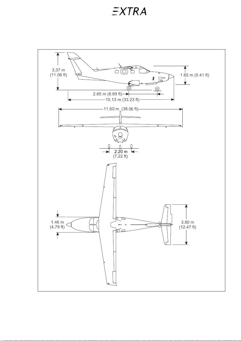
1.3 Dimension Diagram
1.3.a Tree View Drawing
26. January 2011
Figure 1-1
1-7
Page 14

Section 1 Pilot’s Operating Handbook
General EXTRA 500
1.4 General Description
1.4.a Aircraft
The EXTRA 500 is a single engine, turbopropeller, six seat
business aircraft with the following main advantages:
• Fully configured for single pilot IFR-day and night operation.
• Sealed cabin area structurally reinforced for pressurization.
• Lightning strike protected by combination of conducting carbon
structure and metal bondings.
• High wing and T-tail designed empennage with extended
vertical fin, realizing clear aerodynamic and aircraft control
advantages.
• Tricycle, retractable landing gear, equipped with nose wheel
steering capability.
1.4.b Noise Level
The noise level has been established in accordance with FAR 36
Appendix G, as 76.5 dB(A), and with ICAO Annex 16, as
76.7 dB(A).
No determination has been made by the EASA or the FAA that
the noise levels of this aircraft are or should be acceptable or
unacceptable for operation at, into, or out of, any airport.
1-8 26. January 2011
Page 15

Pilot’s Operating Handbook Section 1
EXTRA 500 General
1.4.c Engine
Number of Engines: 1
Engine Manufacturer: Rolls Royce
Engine Model Number is: 250-B17F/2
Main components are:
• propeller reduction gearbox
• compressor
• power and accessory gearbox
• turbine
• combustion section
The power control system is divided into:
• gas producer fuel control
• propeller power turbine governor assembly
• fuel pump and filter assembly
• fuel nozzle
• propeller overspeed governor
• propeller overspeed governor reset solenoid energized by the
overspeed test switch
• coordinator
Takeoff Power (limited to 5 minutes): 450 SHP
Maximum Continuous Power: 380 SHPP
1
) ISA conditions at sea level
1
P
1
26. January 2011
1-9
Page 16

Section 1 Pilot’s Operating Handbook
General EXTRA 500
1.4.d Propeller
Number of Propellers: 1
Propeller Manufacturer: MT-Propeller
Propeller Model Number: MTV-5-1-D-C-F-R(A)/CFR210-56
Number of Blades: 5
Propeller Diameter: 2.10 m (82.68 in.)
Propeller Type: Constant speed, feather, reverse,
governor controlled, and equipped
with electrothermal de-icing system
and a pitch range of 94°.
1.4.e Fuel
Fuel confirming the following military and commercial
specifications are approved for unrestricted use:
ASTM D 1655-03 or later, JET A or A-1
Fuel System Icing Inhibitor:
MIL-DTL-85470B or equivalent in the amount of 0.10 % up to
0.15 % by volume.
1.4.f Capacities
Total Fuel Capacity: 680 l (179.6 U.S. Gallons)
Total Usable fuel: 652 l (172.2 U.S. Gallons)
Unusable fuel: 28 l (7.4 U.S. Gallons)
1-10 26. January 2011
Page 17

Pilot’s Operating Handbook Section 1
EXTRA 500 General
1.4.g Oil
Engine Oil to be used:
Starting min. temperature:
MIL-PRF-7808L or later -54 °C (-65 °F)
MIL-PRF-23699F or later -40 °C (-40 °F)
Total Oil Capacity: 5.18 l (5.47 US Quarts)
1.4.h Maximum Certificated Weights
Maximum allowable Takeoff Weight: 2130 kg (4696 lbs.)
Maximum allowable Landing Weight: 2000 kg (4409 lbs.)
Maximum operational Empty Weight
(including 1 Crew members): 1599 kg (3525 lbs.)
1.4.i Cabin and Entry Dimensions
Cabin Width (maximum): 1.39 m (4.56 ft.)
Cabin Length (front to rear bulkhead): 4.13 m (13.55 ft.)
Cabin Height (maximum): 1.24 m (4.07.ft.)
Entry Door Width: 0.68 m (2.23 ft.)
Entry Door Height: 1.15 m (3.77 ft.)
Emergency Exit Window Width: 0.68 m (2.23 ft.)
Emergency Exit Window Height: 0.50 m (1.64 ft.)
1.4.j Baggage Compartment
A baggage compartment is available in the aft pressure cabin
area behind the passenger seats in the 3rd row. It is primarily
intended for luggage and briefcases up to a total mass of 90 kg.
1.4.k Specific Loadings
Wing Loading (maximum): 149.3 kg/m2 (30.6 lbs./sq.ft.)
Power Loading (maximum): 4.7 kg/BHP (10.4 lbs./BHP)
Note For further information concerning the above mentioned,
refer to Chapter 2, Limitations.
26. January 2011
1-11
Page 18

Section 1 Pilot’s Operating Handbook
General EXTRA 500
1.5 Symbols, Abbreviations and Terminology
1.5.a General Airspeed Terminology and Symbols
CAS Calibrated Airspeed means the indicated speed of an aircraft,
corrected for position and instrument error. Calibrated airspeed
is equal to true airspeed in standard atmosphere at sea level.
KCAS Calibrated Airspeed expressed in “knots”.
GS Ground Speed is the speed of an airplane relative to the ground.
IAS Indicated Airspeed is the speed of an aircraft as shown in the
airspeed indicator when corrected for instrument error. IAS
values published in this handbook assume zero instrument error.
KIAS Indicated Airspeed expressed in “knots”.
TAS True Airspeed is the airspeed of an airplane relative to
undisturbed air which is the CAS corrected for altitude,
temperature and compressibility.
V
Operating maneuvering Speed is the maximum speed at which
O
application of full available aerodynamic control will not
overstress the airplane.
V
Maximum Flap extended speed is the highest speed permissible
FE
with wing flaps in a prescribed extended position.
V
Maximum Landing Gear Extended Speed is the maximum
LE
speed at which an aircraft can be safely flown with the landing
gear extended.
1-12 26. January 2011
Page 19

Pilot’s Operating Handbook Section 1
EXTRA 500 General
V
LO
Maximum Landing Gear Operating Speed is the maximum
speed at which the landing gear can be safely extended or
retracted.
V
Never Exceed Speed is the speed limit that may not be exceeded
NE
at any time.
V
Maximum Structural Cruising Speed is the speed that should
NO
not be exceeded except in smooth air and then only with
caution.
V
Stalling Speed or the minimum steady flight speed at which the
S
airplane is controllable.
V
Stalling Speed or the minimum steady flight speed at which the
SO
airplane is controllable in the landing configuration.
V
Best Angle-of-Climb Speed is the airspeed which delivers the
X
greatest gain of altitude in the shortest possible horizontal
distance.
V
Best Rate-of-Climb Speed is the airspeed which delivers the
Y
greatest gain in altitude in the shortest possible time.
26. January 2011
1-13
Page 20

Section 1 Pilot’s Operating Handbook
d
r
p
r
d
General EXTRA 500
1.5.b Meteorological Terminology
ISA International Standard Atmosphere in which
a The air is a dry perfect gas;
b The temperature at sea level is 15° Celsius (59° Fahrenheit);
c The pressure at sea level is 1013.2 mbar (29.92 inches hg.);
d The temperature gradient from sea level to the altitude at which
the temperature is -56.5°C (-69.7°F) is -1.98°C (-3.564°F) per
1,000 foot and zero above that altitude.
OAT Outside Air Temperature is the free air static temperature,
obtained either from inflight temperature indications or ground
meteorological sources, adjusted for instrument error an
compressibility effects.
Indicated
Pressure
The number actually read from an altimeter when the
barometric subscale has been set to 1013.2 mbar (29.92 in. hg.).
Altitude
Pressure
Altitude
Altitude measured from standard sea level pressure
(1013.2 mbar/29.92 0n. hg.) by a pressure or barometric
altimeter. It is the indicated pressure altitude corrected fo
osition and instrument error. In this Handbook, altimete
instrument errors are assumed to be zero.
Station
Actual atmospheric pressure at field elevation.
Pressure
Wind The wind velocities recorded as variables on the charts of this
Handbook are to be understood as the headwind or tailwin
components of the reported winds.
1-14 26. January 2011
Page 21

Pilot’s Operating Handbook Section 1
EXTRA 500 General
1.5.c Power Terminology
Takeoff Power The maximum power permissible for takeoff (is time limited to
5 min. max).
Maximum
The maximum power for unrestricted periods of use.
Continuous
Power (MCP)
Flight Idle The minimum power setting required to run an engine that will
assure satisfactory engine operation in flight.
Ground Idle The minimum power setting required to run an engine that will
assure satisfactory engine operation on ground.
Reverse Power setting used for negative thrust
(must not be used in flight)
26. January 2011
1-15
Page 22

Section 1 Pilot’s Operating Handbook
f
r
p
y
m
t
r
p
p
p
r
General EXTRA 500
1.5.d E ngi ne C ontr ol s and Instruments
Power Control
Lever
The power control lever allows thrust modulation from Takeof
(full forward position) to Maximum Reverse (aft position).
Specific positions on the lever are:
Max Power, Flight Idle, Ground Idle and Max Reverse.
A “pull to retard” feature will prevent inadvertent leve
movement below the flight idle setting when in flight.
Condition lever The condition lever allows engine starting and shutdown,
ropeller feathering and fuel shutoff, and the capability to var
the propeller speed between 93.6 and 100 %. Specific positions
are: 100 % Propeller Speed (full forward position), Minimu
Propeller Speed setting, and Fuel Shutoff and Propeller
Feathering (aft position). A “pull to retard” feature will preven
inadvertent lever movement below the minimum propelle
speed setting when in flight.
Turbine Outlet
Temperature
(TOT) Gauge
The turbine outlet temperature indicator is the instrument used
to show the temperature of the gases leaving the 2nd wheel of
the gas producer turbine rotor (°C).
Torque Gauge The torque indicator is the instrument used to identify the
propeller shaft torque. The sensed engine torquemeter oil
ressure is converted into an indication of torque output,
expressed in terms of percent (%).
Oil Pressure
Gauge
The oil pressure indicator is the instrument used to show the
ressure (PSI) of the engine oil delivered to the gearbox
housing “header”
assage (downstream the pressure pump,
internal oil filter and oil pressure regulating valve)
Oil Temperature
Gauge
The oil temperature indicator is the instrument used to show the
temperature (°C) of the engine oil delivered to the engine oil
inlet port at the accessory gearbox.
Gas Producer
Speed (N1)
Gauge
The gas producer speed indicator is the instrument used to
identify the rotational speed of the engine gas producer turbine
rotor. The gas producer speed is sensed via the gas produce
gear train by a tach-generator and converted into an indication
of RPM output, expressed in terms of percent (%).
1-16 26. January 2011
Page 23

Pilot’s Operating Handbook Section 1
y
d
f
r
EXTRA 500 General
Propeller Speed
(N2) Gauge
The propeller speed indicator is the instrument used to identif
the rotational speed of the propeller. The propeller speed is
sensed via the power turbine gear train by a tach-generator an
converted into an indication of RPM output.
1.5.e Airplane Performance and Flight Planning Terminology
Climb
Gradient
The demonstrated ratio of the change in height during a portion
of a climb, to the horizontal distance traversed in the same time
interval.
Demonstrated
Crosswind
Velocity
The demonstrated crosswind velocity is the velocity of the cross
wind component for which adequate control of the airplane
during takeoff and landing was actually demonstrated during
certification tests.
1.5.f Weight and Balance
Reference
Datum
An imaginary vertical plane from which all horizontal distances
are measured for balance purposes.
Station A location along the airplane fuselage usually given in terms o
distance from the reference datum.
Arm The horizontal distance from the reference datum to the cente
of gravity (C.G.) of an item.
Moment The product of the weight of an item multiplied by its arm.
Center of
Gravity (C.G.)
The point at which an airplane would balance if suspended. Its
distance from the reference datum is found by dividing the total
moment by the total weight of the airplane.
C.G. Arm The arm obtained by adding the airplane’s individual moments
and dividing the sum by the total weight.
C.G. Limits The extreme center of gravity locations within which the
airplane must be operated at a given weight.
Usable Fuel Fuel available for flight planning.
26. January 2011
1-17
Page 24

Section 1 Pilot’s Operating Handbook
f
General EXTRA 500
Unusable Fuel Fuel remaining after a runout test has been completed in
accordance with certification basis.
Standard
Empty Weight
Basic Empty
Weight of a standard airplane including unusable fuel, full
opera ting fluids and full oil.
Standard empty weight plus optional equipment.
Weight
Payload Weight of occupants, cargo and baggage.
Useful Load Difference between takeoff weight, or ramp weight i
applicable, and basic empty weight.
Zero Fuel
Basic empty weight plus payload but no usable fuel.
Weight
Maximum
Ramp Weight
Maximum
Maximum weight approved for ground maneuver. (It includes
weight of start, taxi and run up fuel.)
Maximum weight approved for the start of the takeoff run.
Takeoff
Weight
Maximum
Maximum weight approved for the landing touchdown.
Landing
Weight
Minimum
Weight
Standard empty weight plus minimum crew (1 pilot) and fuel
for half an hour operating the airplane at maximum continuous
power.
Maximum
Empty Weight
Maximum approved empty weight of airplane including
unusable fuel, full operating fluids and full oil.
1.6 Conversion to U.S. Units
Multiply kg by 2.2 to obtain lbs.
Multiply m by 39.37 to obtain in.
Multiply kgm by 0.866 to obtain in.lbs./100
1-18 26. January 2011
Page 25

Pilot’s Operating Handbook Section 2
EXTRA 500 Limitations
Section 2
Limitations
Table of Contents
Paragraph Page
2.1 Introduction....................................................................................... 2-3
2.2 Airspeed Limitations......................................................................... 2-4
2.2.a Takeoff and Landing Speeds (KCAS) ................................................ 2-4
2.3 Airspeed Indicator Markings........................................................... 2-5
2.4 Reserved............................................................................................. 2-6
2.5 Engine/Propeller Operating Limitations ........................................ 2-6
2.5.a Engine ................................................................................................. 2-6
2.5.b Propeller............................................................................................ 2-10
2.6 Engine Instrument Markings......................................................... 2-11
2.7 Miscellaneous Instrument Markings............................................. 2-12
2.8 Aircraft Weight Limitations........................................................... 2-12
2.9 Center of Gravity Limits................................................................ 2-13
2.10 Maneuver Limits............................................................................. 2-13
2.11 Flight Load Factor Limits.............................................................. 2-13
2.12 Flight Crew Limits.......................................................................... 2-13
2.13 Kinds of Operation ......................................................................... 2-14
2.14 VFR/IFR Operation Equipment List............................................ 2-15
2.15 Fuel Limitations.............................................................................. 2-20
2.15.a Fuel Quantity .................................................................................... 2-20
2.15.b Fuel Pressure..................................................................................... 2-20
2.15.c Fuel Transfer ..................................................................................... 2-21
2.15.d Fuel Flow .......................................................................................... 2-21
2.15.e Low Fuel ........................................................................................... 2-21
2.16 System and Equipment Limitations.............................................. 2-22
2.16.a Electrical Power Supply.................................................................... 2-22
2.16.b Hydraulic System Limits .................................................................. 2-23
2.16.c Cabin Pressurization Limits .............................................................. 2-24
26. January 2011 2-1
Page 26

Section 2 Pilot’s Operating Handbook
Limitations EXTRA 500
2.16.d Tires...................................................................................................2-25
2.17 Other Limitations ............................................................................2-25
2.17.a Maximum Operating Altitude Limit ..................................................2-25
2.17.b Outside Air Temperature Limits........................................................ 2-25
2.17.c Ground Power Supply Limits ............................................................2-25
2.17.d Airstart Envelope Limits....................................................................2-26
2.17.e Structural Temperature/Color Limitation ..........................................2-26
2.17.f Maximum Passenger Seating Limits .................................................2-26
2.17.g Limitations for Electrothermal Anti-ice Devices...............................2-26
2.17.h Flap Limitations.................................................................................2-27
2.17.i Taxiing ...............................................................................................2-27
2.17.j Reverse Utilization Restriction ..........................................................2-27
2.17.k Cross Wind Limitations..................................................................... 2-27
2.18 Reserved ...........................................................................................2-27
2.19 Reserved ...........................................................................................2-27
2.20 Placards............................................................................................2-27
2-2 26. January 2011
Page 27

Pilot’s Operating Handbook Section 2
EXTRA 500 Limitations
2 Limitations
2.1 Introduction
General
This section includes operating limitations, instrument markings
and basic placards, necessary for the safe and efficient operation
of the aircraft, its engine, standard systems and standard
equipment.
Note In case an aircraft is equipped with specific options, the
necessary additional information for safe operation like
limitations, procedures, performance data and other is
shown in section 9 of this POH.
Instrument markings are provided for the corresponding
limitations of the aircraft.
Any exceeding of given limitations has to be reported and
considered by corresponding maintenance and/or inspection
procedures according Maintenance Documentation for EXTRA
500 aircrafts.
The limitations included in this section and in section 9 are
approved by the EASA. Observance of these operating
limitations is required by national regulations.
26. January 2011 2-3
Page 28

Section 2 Pilot’s Operating Handbook
Limitations EXTRA 500
2.2 Airspeed Limitations
Airspeed Limitations are indicated in KCAS. The operational
significance is shown in Figure 2-1 below.
Speed KCAS KIAS Remarks
Maneuvering Speeds VA/Vo
1545 kg (3406 lbs.)
2130 kg (4696 lbs.)
Maximum Flaps Extended
Speed V
15°
FE
30°
Maximum Landing Gear
Operating Speed V
Never Exceed Speed V
LO/VLE
NE
Maximum Structural
Cruising Speed V
NO
Stall Speed in Landing
Configuration V
SO
132
158
120
111
131
156
120
109
142 140
209 207
190 188
61
58
Avoid full or abrupt control
movements above this speeds.
For masses between the given
ones the values are assumed
to be linear.
Do not exceed this speeds
with given flap settings.
Do not exceed this speed
while operating the landing
gear or with landing gear
extended.
Do not exceed this speed in
any operation.
Do not exceed this speed
except in smooth air and with
caution.
Refer to section 5 for stall
speeds at reduced weights.
Figure 2-1
2.2.a Takeoff and Landing Speeds (KCAS)
Refer to Section 4, Normal Procedures.
2-4 26. January 2011
Page 29

Pilot’s Operating Handbook Section 2
EXTRA 500 Limitations
2.3 Airspeed Indicator Markings
Airspeed indicator markings and their color code are marked on
the relevant instrument. See Figure 2-2 below.
Markings
KIAS Value or
Range
White Arc 58 thru 109
(61 thru 111 KCAS)
Green Arc 80 thru 188
(79 thru 190 KCAS)
Yellow Arc 188 thru 207
(190 thru 209 KCAS)
Red Line 207
(209 KCAS)
Figure 2-2
Significance
Full flaps operating range. Lower
limit is maximum mass stalling
speed in landing configuration.
Upper limit is maximum speed
permissible with flaps (30°)
extended.
Normal operating range. Lower
limit is maximum mass stalling
speed with flaps and landing gear
retracted. Upper limit is
maximum structural Cruising
speed.
Operations must be conducted
with caution and only in smooth
air.
Maximum speed for all
operations.
26. January 2011 2-5
Page 30

Section 2 Pilot’s Operating Handbook
Limitations EXTRA 500
2.4 Reserved
2.5 Engine/Propeller Operating Limitations
Engine and propeller operating limitations are listed below:
Note If any limitations are exceeded, a maintenance check and/or
repair as well as an overhaul is required in accordance with
adequate maintenance, inspection documentation.
2.5.a Engine
1 Engine Operating Limits
- Takeoff Power (5 minutes): 450 SHP (336 kW)
- Maximum. Continuous Power: 380 SHP (283 kW)
2 N1 (Gas Producer) Limits:
- Normal operating range 60 % to 105 %
- Maximum 15 seconds 105 % to 106 %
- Above 15 seconds 105 % to 106 %
- Not permitted: above 106 %
3 Propeller Limits
- Minimum normal operating: 1900 RPM (93.6 %)
- Maximum continuous: 2030 RPM (100 %)
- Maximum during transient:
2030 RPM to 2233 RPM (100 % to 110 %)
(15 sec. max above 2132 RPM [105 %])
- Not permitted: above 2233 RPM (110 %)
2-6 26. January 2011
Page 31

Pilot’s Operating Handbook Section 2
EXTRA 500 Limitations
4 TOT (Turbine Outlet Temperature) Limits
- Maximum normal operating/Cruise: 752 °C (1385 °F)
- Maximum takeoff power (5 min.): 810 °C (1490 °F)
- Maximum during power transient (6 sec.): 843 °C (1550 °F)
- Maximum during starts (10 sec.): above 810 °C (1490 °F)
with momentary peak (1 sec.): up to 927 °C (1700 °F)
- Not permitted: above 927 °C (1700 °F)
5 Engine Torque Limits
- Maximum normal operating/Cruise: 92 %
(983 lb ft; 1333 Nm)
- Maximum takeoff power (5 min.): 111 %
(1185 lb ft; 1607 Nm)
- Maximum momentary peak (10 sec.): 115 %
(1218 lb ft; 1651 Nm)
- Not permitted: 115 % (1218 lb ft; 1651 Nm)
6 Oil Temperature Limits
- Maximum normal continuous operating:
- above 40 % TRQ (123 kW; 165 SHP): 82 °C (180 °F)
- below 40 % TRQ (123 kW; 165 SHP): 107 °C (225 °F)
- Maximum takeoff (5 min.): 107 °C (225 °F)
- Not permitted: above 107 °C (225 °F)
26. January 2011 2-7
Page 32

Section 2 Pilot’s Operating Handbook
Limitations EXTRA 500
7 Use of Oil Grades Temperature Dependent
- At oil temperature –54 °C (-65 °F) or above:
MIL-PRF-7808L or later
- At oil temperature –40 °C (-40 °F) or above:
MIL-PRF-23699F or later
Minimum starting:
- MIL-PRF-7808L or later -54 °C (-65 °F)
- MIL-PRF-23699F or later -40 °C (-40 °F)
Caution Only discretionary mixing of oil series is permitted without
time penalty. If brands of oils are changed, it is
recommended this change be accomplished gradually using
a "TOP-OFF" method or by draining and refilling.
Note Oil series and brand used shall be recorded in engine
module logbook.
8 Oil Pressure Limits
- Maximum normal continuous Operation: 130 psig (896 kPa)
- Minimum normal continuous Operation:
at 94 % N1 and above 120 psig (872 kPa)
at 85 % N1 up to 94 % N1 90 psig (621 kPa)
below 85 % N1 50 psig (345 kPa)
- Minimum in beta range Operation:
at 94 % N1 and above 105 psig (769 kPa)
at 85 % N1 up to 94 % N1 75 psig (518 kPa)
below 85 %.- N1 35 psig (242 kPa)
- Minimum during start
when 59 % N
is reached: Positive indication
1
- Not permitted: above 130 psig (896 kPa)
Note During cold weather operation, 150 psig (1034 kPa) oil
pressure is allowable at minimum power, following an
engine start. Stay in ground idle power setting as long as oil
pressure exceeds max continuous pressure limit (130 psig)
during engine warm up.
2-8 26. January 2011
Page 33

Pilot’s Operating Handbook Section 2
EXTRA 500 Limitations
9
Fuel Grades
Primary Fuel:
ASTM D 1655-03 or later, grade JET A or A-1
Cold weather fuel:
ASTM D 1655-03 or later, grade JET A or A-1 with anti ice
additive MIL-DTL-85470B or later
Caution Adding anti-icing additive into the fuel during
refueling.
Proper mixing of anti icing additive with fuel is
extremely important, because concentration in excess
of the recommended (0.10 % up to 0.15 % by volume)
will result in detrimental effects to the fuel tanks.
Note JET A and JET A-1 fuels are not restricted from use at
ambient temperatures below –18
°C (0 °F); however,
special provisions for starting (preheat to the engine
fuel control area) must be made. Once started, engine
operation will be satisfactory in outside temperatures
down to – 32 °C (-2 5 °F) for JET A and JET A-1.
10 Use of Fuel Grades Temperature Dependent
Starting and operating temperature ranges:
Ambient temperature
Fuel grade for
Starting Operating
at +38 °C(+100 °F)
Primary
down to +4 °C (+40 °F)
below +4 °C (+40 °F)
down to-18 °C (+0 °F)
below -18 °C(+0 °F)
down to -32 °C (-25 °F)
Cold weather
preheated
Cold weather
Cold weather
Figure 2-3
26. January 2011 2-9
Page 34

Section 2 Pilot’s Operating Handbook
Limitations EXTRA 500
2.5.b Propeller
Propeller manufacturer: MT-Propeller
Propeller model number: MTV-5-1-D-C-F-R(A)/CFR210-56
Propeller diameter: 210 cm ±0.5 cm (82.68 in. ±0.2 in.)
Blade angle settings at Low pitch 8° ±0.2°
radius 790 mm (31.1 in.): Feather/course pitch 79° ±1°
Reserve –15° ±1°
Max. takeoff and continuous speed: 2030 RPM
2-10 26. January 2011
Page 35

Pilot’s Operating Handbook Section 2
EXTRA 500 Limitations
2.6 Engine Instrument Markings
Engine instrument markings and their colour significance are
shown in Figure 2-4 below.
Instrument
TOT
°C (°F)
Red
Line
Min.
Limit
Yellow Arc Green Arc Yellow Arc
Caution
Range
- -
Normal
Operating
0 - 752
(32 - 1385)
Caution or
Takeoff
752 - 810
(1385 -
1490)
810 (1490)
843 (1550) ∇
927 (1700) ◊
Torque % - - 0 - 92 92 - 111
Prop. “N2”
- 1218 - 1900 1900 - 2030 -
RPM
Gas P. “N1”
- - 60 - 105 -
%
Oil Temp.
°C (°F)
Oil Pressure
- -
35 35 - 90 90 - 130 - 130
0 - 82
(32 - 180)
82 - 107
(180 - 225)
PSI
1
) Red Arrowhead: Maximum Transient Limit
2
) Red Diamond: Maximum Temperature Starting
Figure 2-4
Red
Line
Max.
Limit
111
2030
1
2233 ∇
105
1
106 ∇
107 (225)
1
2
26. January 2011 2-11
Page 36

Section 2 Pilot’s Operating Handbook
Limitations EXTRA 500
2.7 Miscellaneous Instrument Markings
Miscellaneous instrument markings are shown in Figure 2-5
below.
Instrument
Red
Line
Min.
Limit
Yellow
Arc
Caution
Range
Green
Arc
Normal
Operating
Yellow
Arc
Caution
or
Red
Line
Max.
Limit
Cabin Altitude, ft 10.000
Cabin Differential
0 – 5.5 5.5
Pressure, (PSI)
Fuel Quantity collector
0 l
compartment (LH/RH)
Fuel Quantity main
0 l
compartment (LH/RH)
Fuel Quantity auxiliary
0 l
compartment (LH/RH)
Figure 2-5
2.8 Aircraft Weight Limitations
Maximum Ramp Weight (Taxi Weight): 2130 kg (4696 lbs.)
Maximum Takeoff Weight: 2130 kg (4696 lbs.)
Maximum Landing Weight: 2000 kg (4409 lbs.)
Maximum Zero Wing Fuel Weight: 1945 kg (4289 lbs.)
Maximum Empty Weight: 1445 kg (3186 lbs.)
(incl. unusable fuel)
Maximum Weight
in Baggage Compartment: 90 kg ( 198 lbs.)
2-12 26. January 2011
Page 37

Pilot’s Operating Handbook Section 2
EXTRA 500 Limitations
2.9 Center of Gravity Limits
Center of gravity ranges (M.A.C.) are as follows:
Note Values are for landing gear extended configuration.
Forward C.G.: 18 % M.A.C. up to TOW 1600 kg (3527 lbs.)
25 % M.A.C. up to MTOW 2130 kg (4696 lbs.)
Aft C.G.: 34.5 % M.A.C.
Note C.G. range varies lineary between mass limits. M.A.C. is
1322 mm (52.05 in.).
0 % M.A.C. is at 3200 mm.
2.10 Maneuver Limits
The EXTRA 500 is a normal category aircraft. The normal
category is applicable to aircraft intended for non-aerobatic
operations. These include any maneuvers incidental to normal
flying, stalls (except whip stalls), lazy eights, chandelles and
turns in which the angle of bank is not more than 60°.
Aerobatic maneuvers, including spins are prohibited.
2.11 Flight Load Factor Limits
Wing flaps UP: -1.5 ≤ n ≤ +3.8
Wing flaps 15° and 30°: -0 ≤ n ≤ +2.0
Intentional negative load factors prohibited.
2.12 Flight Crew Limits
Minimum certificated flight crew is one (1) pilot on the left
seat.
Note For further crew requirements, national regulations must
be observed.
26. January 2011 2-13
Page 38

Section 2 Pilot’s Operating Handbook
Limitations EXTRA 500
2.13 Kinds of Operation
The aircraft is cleared for day and night VFR and IFR flights if
appropriate equipment is installed.
Flights into icing conditions are prohibited.
Ground and flight operation in both falling and blowing snow is
prohibited.
Note For special crew requirements, national regulations must be
observed. Presently no NDB-approaches are possible.
IFR-equipment does not include an ADF receiver.
The aircraft is certified for B-RNAV operation. P-RNAV
operation and GNSS approach are prohibited.
For kinds of operation equipment lists refer to section 2.14
VFR/IFR Operation Equipment Lists.
2-14 26. January 2011
Page 39

Pilot’s Operating Handbook Section 2
EXTRA 500 Limitations
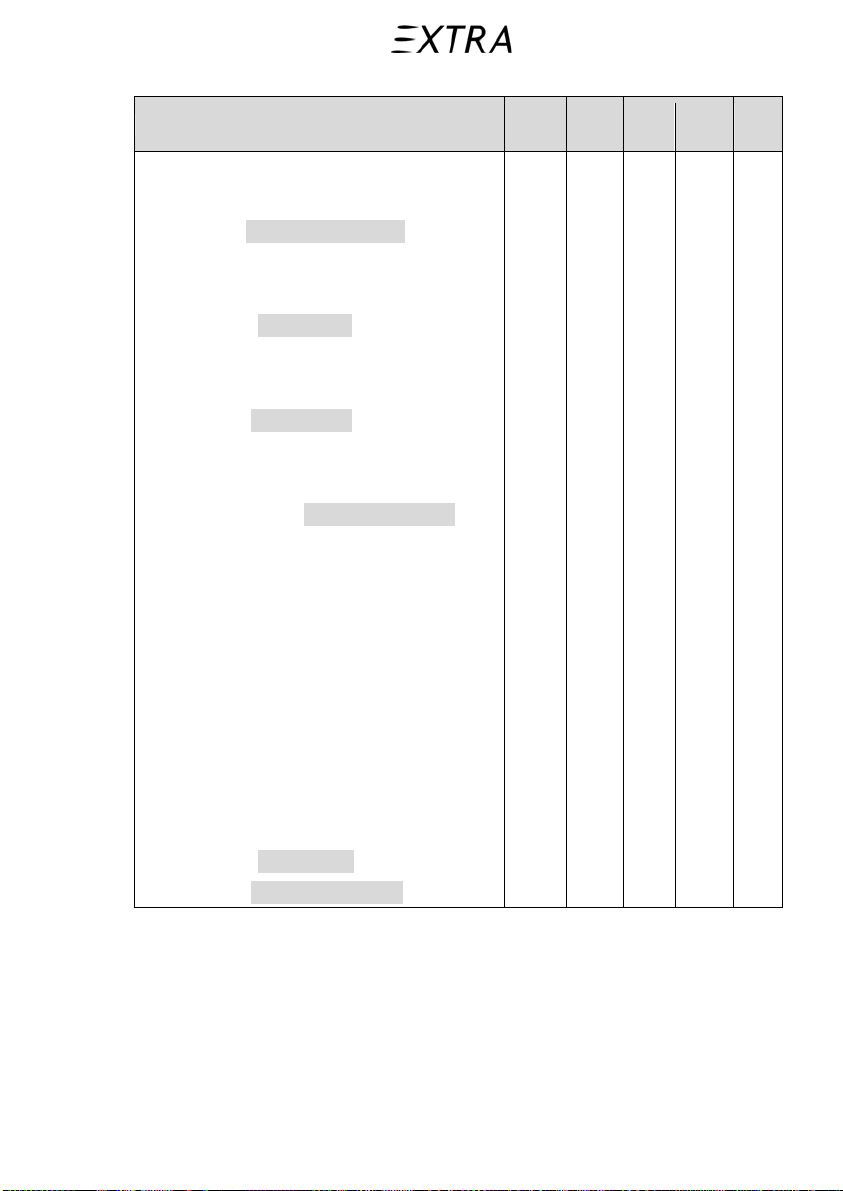
2.14 Kinds of Operation Equipment List
VFR-
VFR-
IFR-
System and/or Equipment
Day
Night
Air Conditioning
Environmental bleed shut off valve 1 1 1 1
Windshield defrost system 1 1 1 1
Warning light: BLEED OVERTEMP 1 1 1 1
Pressure Cabin (above FL 120)
Automatic bleed temperature control system 1 1 1 1
Automatic bleed mass flow control system 1 1 1 1
Cabin pressure controller 1 1 1 1
Outflow control valve 1 1 1 1
Outflow safety valve 1 1 1 1
Cabin altitude indicator 1 1 1 1
Cabin diff. press. indicator 1 1 1 1
Day
IFR-
Night
ICE
Warning light: CABIN PRESSURE 1 1 1 1
Auto Flight
Autopilot 1 1
Turn & bank indicator (electric) 1 1
Communications
Audio panel 1 1
ELT 406 MHz 1 1 1 1
Electrical Power
Battery 1 1 1 1
(Starter-) generator 1 1 1 1
26. January 2011 2-15
Page 40

Section 2 Pilot’s Operating Handbook
Limitations EXTRA 500
VFR-
VFR-
IFR-
System and/or Equipment
Day
Night
Day
IFR-
Night
ICE
Standby alternator 1 1
Voltage indicator 1 1 1 1
Ammeter (generator & standby alternator) 1 1 1 1
Warning light: GENERATOR FAIL 1 1 1 1
Caution light: LO VOLTAGE 1 1 1 1
Caution light: STANDBY ALTERN ON 1 1
Safe operation light: EXTERNAL POWER 1 1 1 1
Equipment / Furnishings
Safety belt and shoulder harness * * * *
Fire Protection
Fire extinguisher 1 1 1 1
Flight Controls
Flap system 1 1 1 1
Flap position indication 1 1 1 1
Pitch trim system 1 1 1 1
Pitch trim position indicator 1 1 1 1
Warning light: FLAPS 1 1 1 1
Flap position indication (1x amber, 2x green) 1 1 1 1
Fuel
Electric fuel pump 2 2 2 2
Fuel quantity indicators 6 6 6 6
Fuel transfer system (left & right) 1 1 1 1
Caution light: FUEL TRANS LEFT 1 1 1 1
Caution light: FUEL TRANS RIGHT 1 1 1 1
Caution light: FUEL LOW LEFT 1 1 1 1
2-16 26. January 2011
Page 41

Pilot’s Operating Handbook Section 2
EXTRA 500 Limitations
VFR-
VFR-
IFR-
System and/or Equipment
Day
Night
Day
IFR-
Night
ICE
Caution light: FUEL LOW RIGHT 1 1 1 1
Caution light: FUEL FILTER BYPASS 1 1 1 1
Warning light: FUEL PRESS 1 1 1 1
Hydraulic Power
Hydraulic power pack 1 1 1 1
Caution light: HYDRAULIC PUMP 1 1 1 1
Ice and Rain Protection
Heated engine inlet 1 1 1 1
Warning light: WINDSHIELD HEAT FAIL 1 1 1 1
Safe operation light: INTAKE HEAT 1 1 1 1
Safe operation light:
WINDSHIELD HEAT ON
1 1 1 1
Indicating / Recording Systems
IFD, incl. COM, NAV, GPS, Altimeter,
2 2 2 2
Airspeed indicator, Attitude indicator,
Vertical speed indicator, clock
Aural warning system
1 1 1 1
(over-speed, gear, stall)
Cockpit loudspeaker 1 1 1 1
Landing Gear
Landing gear position indication (3x green) 1 1 1 1
Warning light: GEAR WARN 1 1 1 1
Lights
Flashlight 1 1
Anti-collision light system (strobe) 1 1 1 1
Landing light 1 1
26. January 2011 2-17
Page 42

Section 2 Pilot’s Operating Handbook
Limitations EXTRA 500
VFR-
VFR-
IFR-
System and/or Equipment
Day
Night
Day
IFR-
Night
ICE
Navigation light system (reco) 1 1 1 1
Instrument light system (incl. test function) 1 1
Cockpit controls illumination
1 1
(luminous films)
Glare light 1 1
Safe operation light: LANDING LIGHT 1 1
Safe operation light: RECOGN LIGHT 1 1 1 1
Navigation
Standby airspeed indicator 1 1
Pitot tube 1 1
Pitot tube, heated 2 2
Standby altimeter 1 1
Static source 2 2
Static source, heated 2 2
IAT indicator 1 1 1 1
Magnetic compass 1 1 1 1
Standby attitude gyro (electric) 1 1
Transponder 1 1 1 1
Stall warning system 1 1
Stall warning system (heated) 1 1
Warning light: STALL WARN 1 1 1 1
Warning light: STALL HEAT 1 1
Caution light: PITOT HEAT LEFT 1 1
Caution light: PITOT HEAT RIGHT 1 1
Caution light: STATIC HEAT LEFT 1 1
Caution light: STATIC HEAT RIGHT 1 1
2-18 26. January 2011
Page 43
Pilot’s Operating Handbook Section 2
EXTRA 500 Limitations
VFR-
VFR-
IFR-
System and/or Equipment
Day
Night
Day
IFR-
Night
ICE
Pneumatic
Pneumatic pressure regulator 1 1 1 1
Caution light: PNEUMATIC LOW 1 1 1 1
Doors
Warning light: AFT DOOR 1 1 1 1
Propellers
Caution light: LOW PITCH 1 1 1 1
Ignition
Safe operation light: IGNITION ACTIVE 1 1 1 1
Engine Indicating
Fuel flow indicator 1 1
Fuel pressure indicator 1 1 1 1
N2 (Prop) RPM indicator 1 1 1 1
N1 (Gas-generator) RPM indicator 1 1 1 1
Torque indicator 1 1 1 1
TOT indicator 1 1 1 1
Oil pressure indicator 1 1 1 1
Oil temperature indicator 1 1 1 1
Warning light: OIL PRESS 1 1 1 1
Caution light: CHIP DETECTION 1 1 1 1
*)
one for each seat occupied
Figure 2-6
26. January 2011 2-19
Page 44

Section 2 Pilot’s Operating Handbook
Limitations EXTRA 500
2.15 Fuel Limitations
2.15.a Fuel Quantity
Fuel quantity is based on fuel grade JET A-1 at 15 °C (59 °F)
with specific gravity 0.814 kg/l and shown in table (Figure 2-7)
below:
Note The maximum allowable fuel unbalance is 106 liter (28 U.S.
Gallons).
Note The left and right wing are subdivided in three compart-
ments each; the collector, main and auxiliary compartment.
Wing Tank Liter lbs Kg US Gal. Remark
Collector
2 x 37.4 2 x 67.1 2 x 30.4 2 x 9.9
Compartment
Main
2 x 196.6 2 x 352.9 2 x 160.0 2 x 51.9
Compartment
Auxiliary
2 x 106.0 2 x 190.3 2 x 86.3 2 x 28.0
Compartment
Total Capacity 680.0 1220.5 553.5 179.7
Unusable Fuel 2 x 14.0 2 x 25.1 2 x 11.4 2 x 3.7
Usable Fuel 652.0 1170.3 530.7 172.3
One indicator
each side
One indicator
each side
One indicator
each side
Figure 2-7
2.15.b Fuel Pressure Note The fuel pressure shall not exceed 25 psig.
If fuel pressure at engine fuel pressure sensing port drops below
1.5 psig (3 in Hg), the red FUEL PRESS warning light on the
annunciator panel illuminates.
2-20 26. January 2011
Page 45

Pilot’s Operating Handbook Section 2
EXTRA 500 Limitations
2.15.c Fuel Transfer
If fuel pressure in the left and/or right fuel transfer wing system
drops below 10 psi (700 hPa), the amber FUEL TRANS LEFT
and/or FUEL TRANS RIGHT caution light on the annunciator
panel illuminate.
2.15.d Fuel Flow
The maximum fuel flow at takeoff power setting at ISA
conditions is 156 ltr/h (280 lbs/h).
2.15.e Low Fuel
The illumination of the amber FUEL LOW LEFT and/or FUEL
LOW RIGHT caution lights on the annunciator panel indicates
that the remaining fuel quantity from the relevant fuel tank is
low and that the fuel selector valve should be switched within
next five minutes to the opposite wing tank only. This low fuel
condition may be verified by the individual fuel quantity
indicators.
26. January 2011
2-21
Page 46

Section 2 Pilot’s Operating Handbook
Limitations EXTRA 500
2.16 System and Equipment Limitations
2.16.a Electrical Power Supply 1 Starter Generator
The maximum continuous Starter generator current Output is
limited to 200 Amps (28 V DC).
2 Starter Operation Limits
Caution The Starter Operation cycle is limited to 30 seconds.
If several Starter cycles are necessary, the following Starter
generator and engine cooling periods must be observed:
st
1
cycle: 30 seconds ON - 1 minute OFF
2nd cycle: 30 seconds ON - 1 minute OFF
rd
3
cycle: 30 seconds ON - 30 minutes OFF
3 Standby Alternator
If bus voltage drops below 26 ±0.2 V DC, the standby operates
automatically. The standby alternator System is limited to
20 Amps continuous electrical current output.
However, transient operations of greater than 20 Amps for no
more than 5 consecutive minutes may be conducted.
Flashing of the STDBY ALT ON light on the annunciator panel
indicates, that the standby alternator is:
- delivering power to the bus
- producing more than rated 20 Amps electrical current.
A load of 20 Amps or less is indicated by steady illuminating of
the STBY ALT ON annunciator light.
For full rated power output a minimum N l of 93 % is necessary.
4 Bus Voltage
Normal generator operation: 28.5 ±0.5 VDC (Standard setting)
Standby alternator operation:
26.0 ±0.2 down to 25.0 VDC at rated 20 Amps.
2-22 26. January 2011
Page 47

Pilot’s Operating Handbook Section 2
EXTRA 500 Limitations
2.16.b Hydraulic System Limits 1
Hydraulic powerpack (Landing Gear Retraction)
Oil Grade: MIL-H-5606G and MIL-PRF-5606H or later (*)
Reservoir content: 1.1 L (1.16 U.S. Quarts)
Max. operating pressure: 12.0 MPa (1740 psi)
2 Wheel Brakes
Oil Grade: MIL-H-5606G and MIL-PRF-5606H or later (*)
Reservoir content: 0.148 L (5.0 Oz)
Max. operating pressure : 5.5 MPa (800 psi)
3 Oleo Shock Absorber
Oil Grade: MIL-H-5606G and MIL- PRF-5606H or later (*)
Normal operating pressure: Main gear: 5.7 MPa (827 psi)
Nose gear: 1.5 MPa (218 psi)
(*) Recommended hydraulic fluid type is: AeroShell Fluid 4 or
AeroShell Fluid 41.
26. January 2011
2-23
Page 48

Section 2 Pilot’s Operating Handbook
Limitations EXTRA 500
2.16.c Cabin Pressurization Limits
The pressurized cabin operation altitude is up to flight altitudes
of 25.000 feet.
Max. cabin pressure differential is 5.5.psi (380 hPa) for normal
operation.
Max. structural pressure differential is 5.8 psi (400 hPa)
Max. cabin pressure altitude: 7.950 ft.
Note A red CABIN PRESSURE warning light on the annunciator
panel illuminates when cabin altitude exceeds 10.000 feet
±500 feet or when maximal cabin pressure differential is
exceeded.
Reaching a cabin altitude of 8.500 feet ±500 feet the warning
light extinguishes.
Landings with cabin pressurized are prohibited.
2-24 26. January 2011
Page 49

Pilot’s Operating Handbook Section 2
EXTRA 500 Limitations
2.16.d Tires
Maximum tire limit speed: 140 KCAS
Nose wheel tire size: 5.0-5 6 ply
Nose wheel tire pressure: 0.35 MPa (51 psi)
Main wheel tire size: 15 x 6.0-6 10 ply
Main wheel tire pressure: 0.51 MPa (74 psi)
2.17 Other Limitations
2.17.a Maximum Operating Altitude Limit
The maximum certified aircraft operating altitude is 25.000 ft.
2.17.b Outside Air Temperature Limits
Minimum indicated outside air temperature (IAT) for engine
starting:
- primary fuel: +4 °C (+40 °F)
- alternate cold weather fuel: -18 °C (0 °F)
- alternate cold weather fuel (preheated): -32 °C (-25 °F)
Note It is recommended to use auxiliary power source or preheat
to the battery for starting engine below –18 °C (0 °F)
Minimum indicated outside air temperature (IAT) for normal
operation:
- primary fuel: +4 °C (+40 °F)
- alternate cold weather fuel: -32 °C (-25 °F)
Maximum indicated outside air temperature (IAT):
Aircraft shall not be operated when takeoff ambient temperature
exceeds ISA+23 °C (ISA+41 °F) i.e. +38 °C (+100 °F) on SL.
2.17.c Ground Power Supply Limits
The maximum setting for ground power supply are:
- Voltage: 28 V DC
- Current: 1200 Amps
26. January 2011
2-25
Page 50

Section 2 Pilot’s Operating Handbook
Limitations EXTRA 500
2.17.d Airstart Envelope Limits
At altitude 25.000 feet or below:
- Begin inflight starting procedure within l minute after engine
shutdown
(Power lever: “flight idle”)
- Airspeed range for restart: 100 up to 140 KIAS
2.17.e Structural Temperature/Color Limitation
- Minimum Structural component temperature: -54 °C (-65 °F)
- Maximum Structural component temperature:
+72 °C (+161.6 °F)
Note Not to exceed the maximum temperature limit, color
specification for composite structure (manufacturer
document EA-05205.19) has to be complied with.
2.17.f Maximum Passenger Seating Limits
Refer to regulations of national authority.
The number of passengers on board is limited by the approved
seating configuration installed but must not exceed five (5)
persons. Airplane weight and balance limits have to be
considered.
2.17.g Limitations for Electrothermal Anti-ice Devices
Maximum operating time of propeller heat without running
engine is: 10 seconds.
Maximum operating time of pitot-, static- and stall heat on
ground (test function) is: 10 seconds.
Caution Do not operate pitot-, static- and stall heat during flight at
OAT above +20 °C (68 °F).
2-26 26. January 2011
Page 51

Pilot’s Operating Handbook Section 2
EXTRA 500 Limitations
2.17.h Flap Limitations
Approved landing position: 30°
Approved takeoff position: 15°
2.17.i Taxiing
Minimum turning radius of aircraft is 20.8 m (68.2 ft).
2.17.j Reverse Utilization Restriction
Positioning of power lever below the flight idle stop in flight is
prohibited.
2.17.k Cross Wind Limitations
Maximum permissible cross wind for takeoff, landing: 20 kt.
2.18 Reserved
2.19 Reserved
2.20 Placards
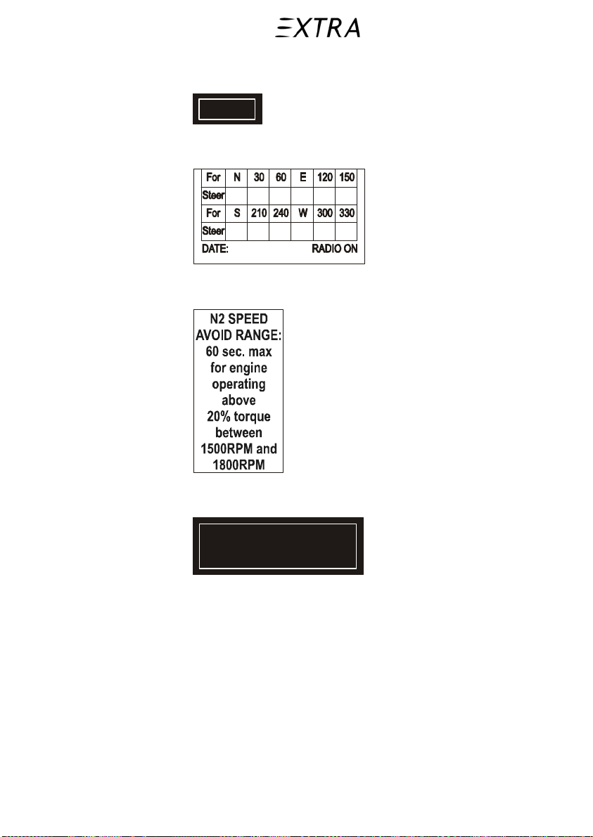
The following information must be displayed in the form of
composite or individual placards.
The placards marked with (*) have to be used, when the aircraft
is requested to be on the German register only.
Note Placards which shall be red are outlined here on a grey
ground.
All red placards and additionally the placards describing the
opening and closing the door are phosphorescent.
26. January 2011
2-27
Page 52

Section 2 Pilot’s Operating Handbook
Limitations EXTRA 500
2.20.a Internal Placards
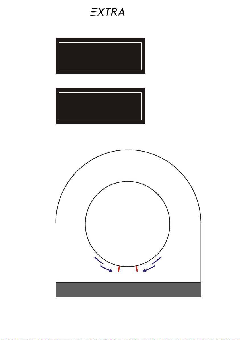
On instrument panel in full view of the pilot:
The markings and placards installed in this airplane
contain operating limitations which must be complied
with when operating this airplane in the normal category.
Other operating limitations which must be complied with
when operating this airplane in this category are
contained intheAirplaneFlight Manual.
WARNING:
This aircraft is not approved
for flight in icing conditions
The airplane is approved for Day and Night,
VFR /IFR oper ation.
Landing with cabin pressurized prohibited.
No acrobatic maneuvers, including spins, approved.
PITOT HEAT
must be ON below 20°C (68°F)
Near to the pilot’s airspeed indicator:
Operating Maneuvering Speed at 1545kg (3406 lbs): 131 KIAS
at MTOW of 2130kg (4696 lbs): 156 KIAS
Maximum Landing Gear Operation Speed: 140 KIAS
Maximum Landing Gear Extended Speed: 140 KIAS
On windshield center strut:
Compass readings
only reliable when
WINDSHIELD HEAT OFF
2-28 26. January 2011
Page 53
Pilot’s Operating Handbook Section 2
EXTRA 500 Limitations
Near vent fan control switch (2x):
VENT
Next to magnetic compass:
Near RPM Indicator:
Next to wing flap control:
26. January 2011
Wing Flaps UP
before opening the door
2-29
Page 54
Section 2 Pilot’s Operating Handbook
Limitations EXTRA 500
Baggage compartment (RH, behind RH seat of 3rd row):
Maximum w eight
in baggage compartment
90 kg (198 lbs.)
or
Höchstzulässiges Gewicht
im Gepäckabteil
90 kg (198 lbs.)
(*)
At fuel selector valve (on floor between pilot’s and copilot’s
seat):
BOTH
652 L (172 US Gal.) Usable
LEFT
326 L
(86 Gal.)
PUSH
& TURN
OFF
PUSH
& TURN
RIGHT
326 L
(86 Gal.)
FUEL SELECTOR VALVE
2-30 26. January 2011
Page 55

Pilot’s Operating Handbook Section 2
EXTRA 500 Limitations
Below emergency exit (inside cabin):
EMERGENCY EXIT
swivel up and turn handle
and pull window inside
or
NOTAUSSTIEG
Griff drehen un d
Fenster here inziehen
(*)
Next to emergency handle (inside cabin)
E
P
O
N
26. January 2011
E
U
P
U
O
F
A
(*)
N
or
A
F
2-31
Page 56

Section 2 Pilot’s Operating Handbook
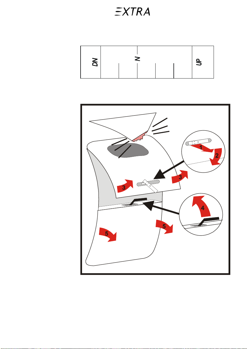
Limitations EXTRA 500
Next to cabin door (inside cabin):
To open door To close door
Wing Flaps UP?
Upper part:
depress safety button
and keep depressed,
rotate handle to the left,
deploy upper door
Lower part:
rotate sill lever up
and deploy lower door
In emergency case push upper door strongly against
extended wing flaps. Flap edge is deformable.
or
Lower part:
pull up by means of cables,
rotate sill lever down to lo ck
check 4 inspection glasses
green
Upper part:
pull down,
rotate handle to the right
until it is locked
check 4 inspection glasses
green
Öffnen der Tür
Klappen eingefahren?
Oberer Teil:
Sicherungsknopf drücken
und gedrückt halten
Griff nach links drehen
obere Tür hochklappen
Unterer Teil:
Hebel hochklappen
untere Tür herunterklappen
Schließen der Tür
Unterer Teil:
Tür an Kabeln
heraufziehen
Hebel herunterklappen
prüfe 4 Sichtfenster grün
Oberer Teil:
Tür herunterziehen
Griff nach rechts drehen
bis er einrastet
prüfe 4 Sichtfenster grün
Im Notfall obere Tür kräftig ge gen ausgefahrene
Klappe drü cken. Klappe lä ßt sich deformieren
(*)
2-32 26. January 2011
Page 57
Pilot’s Operating Handbook Section 2
EXTRA 500 Limitations
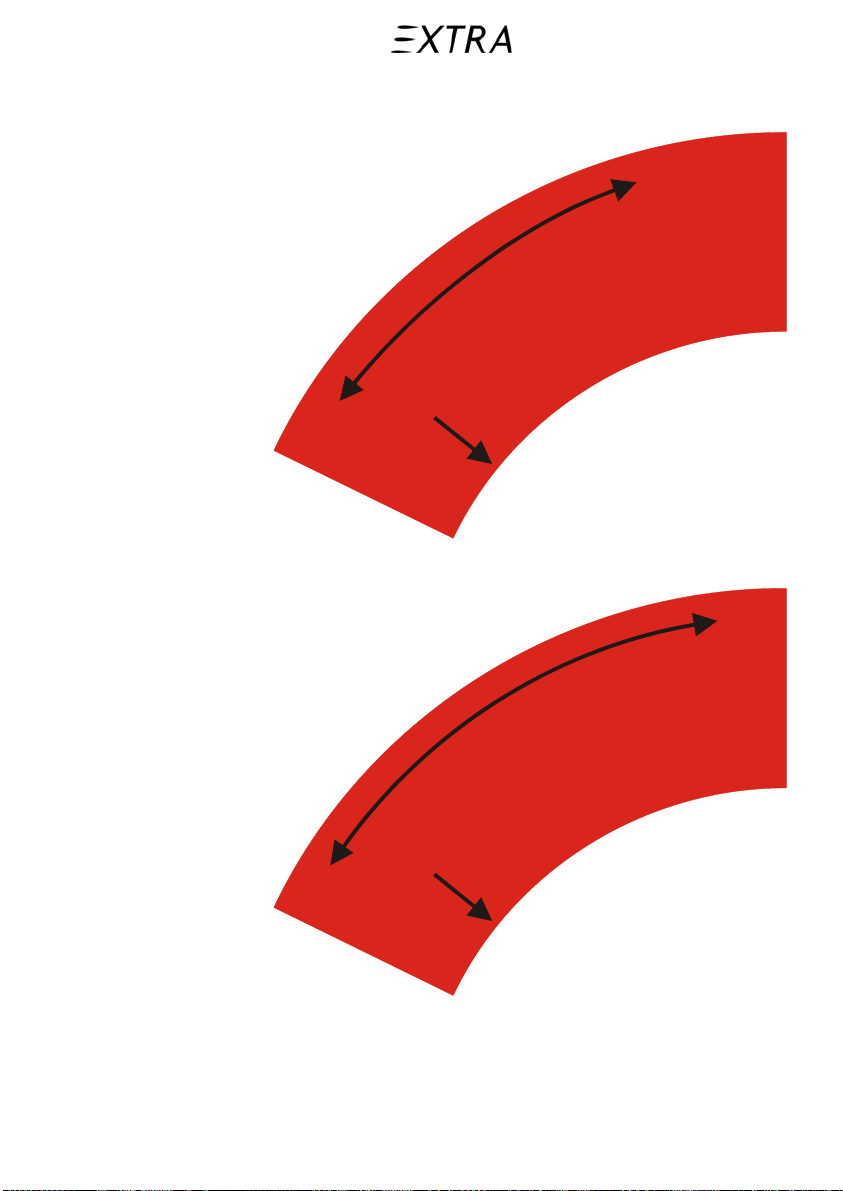
On upper cabin door nest to operating handle:
CLOSED
OPEN
PUSH
BUTTON
or
26. January 2011
ZU
AUF
KNOPF
DRÜCKEN
(*)
2-33
Page 58
Section 2 Pilot’s Operating Handbook
Limitations EXTRA 500
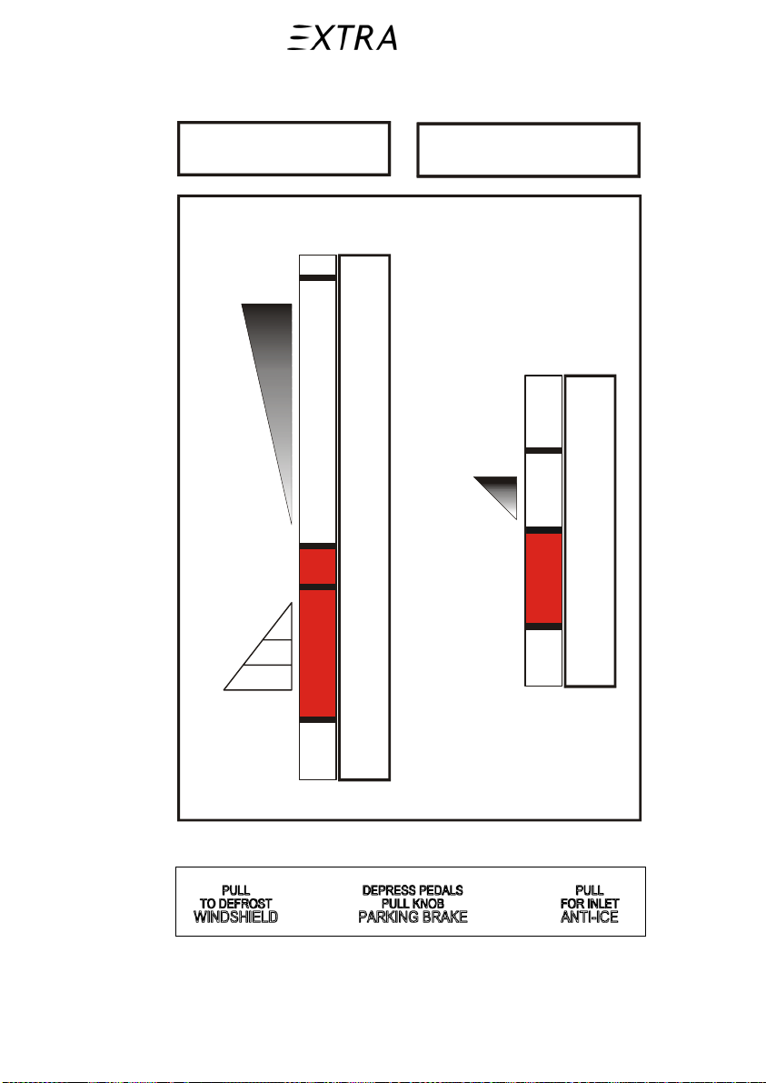
At power column (center pedestal):
POWER
MAX
POWER
FLT IDLE
PULL to retard
GRD IDLE
CONDITION
MAX
PROP RPM
FUEL ON
PULL to retard
FUEL OFF/
FEATHER
MAX
REVERSE
At middle console panel (near respective control):
2-34 26. January 2011
Page 59
Pilot’s Operating Handbook Section 2
EXTRA 500 Limitations
At trim position indicator (middle console; right side of trim
wheel):
2.20.b External Placards
On the fuselage surface just in front of the door:
26. January 2011
2-35
Page 60

Section 2 Pilot’s Operating Handbook
Limitations EXTRA 500
To open door
Wing Flaps UP?
Upper part:
Pull out handle
completely and
rotate handle to the right,
deploy upper door
Lower part:
rotate sill lever up
and deploy lower door
In emergency case pull upper door strongly against
extended wing flaps. Flap edge is deformable.
To close door
Lower part:
pull up by means of cables,
rotate sill lever down
to lock
Upper part:
pull down,
rotate handle to the left
and sink
or
Öffnen der Tür Schließen der Tür
Klappen eingefahren?
Oberer Teil:
Griff ganz herausziehen
und nach rechts drehen
obere Tür hochklappen
Unterer Teil:
Hebel hochklappen
untere Tür heru nterk la ppen
Unterer Teil:
Tür an Kabeln
heraufziehen
Hebel herunter klap pen
Oberer Teil:
Tür herunterziehen
Griff nach links drehen
und versenken
Im Notfall ob ere Tür kräftig gegen ausgefahr ene
Klappe ziehen. K lap pe l äßt sich deformie ren
(*)
2-36 26. January 2011
Page 61
Pilot’s Operating Handbook Section 2
EXTRA 500 Limitations
On door handle (outside):
O
P
E
N
or
A
U
F
(*)
On emergency exit (outside):
26. January 2011
Emergency Exit
or
Notausstieg
(*)
2-37
Page 62
Section 2 Pilot’s Operating Handbook
Limitations EXTRA 500
Next to the emergency exit operating handle:
Remove cover,
rotate handle
and push window in sid e
or
Schauglas abnehmen,
Griff drehen und
Notausstieg hineindrücken
(*)
On the cover of the emergency exit operating handle:
O
N
E
P
O
P
E
N
or
A
F
U
U
F
A
(*)
2-38 26. January 2011
Page 63
Pilot’s Operating Handbook Section 2
EXTRA 500 Limitations
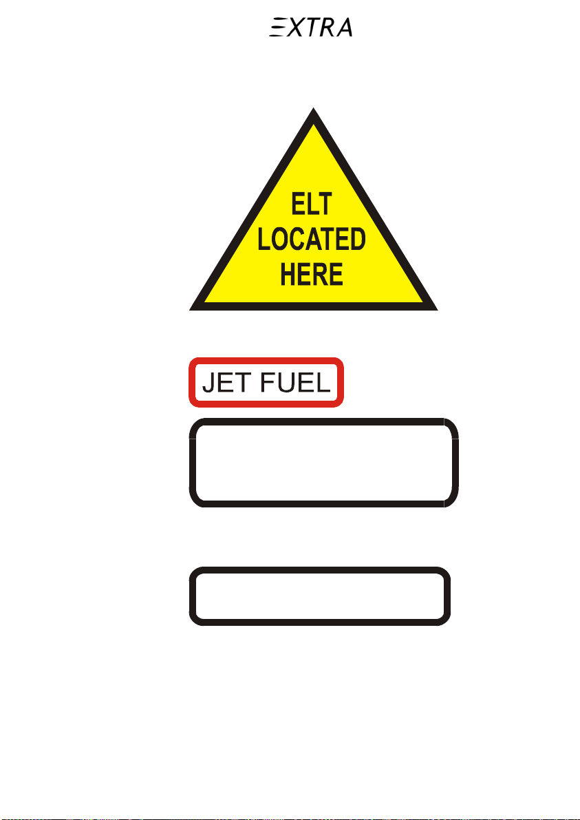
At tail cone above air outlet air condition module (left side of
rear fuselage):
(yellow colored)
On top of the wing next to each fuel filler (4x):
26. January 2011
For permissible fuel
grades refer to AFM
Next to each fuel tank vent opening on the lower side of the
wing (4x):
FUEL TANK VENT
2-39
Page 64
Section 2 Pilot’s Operating Handbook
Limitations EXTRA 500
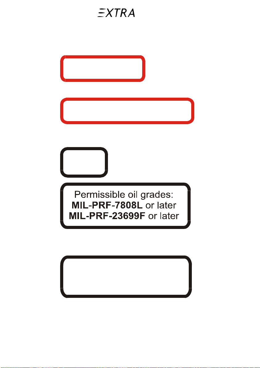
Next to each fuel tank drain (8x), sump drain on the lower side
of the wing (2x) and near the lower fuel overboard drain line
(1x; bottom side of the fuselage, aft of the nose gear bay):
FUEL DRAIN
Next to the fuel filter drain (aft of cowling bottom part):
FUEL FILTER DRAIN
Outside/inside the oil access panel (right top of the engine
cowling):
OIL
On the right keel beam next to the refill opening of the
reservoir:
HYDRAULIC FLUID
MIL-H-5606G and
MIL-PRF-5606H or later
2-40 26. January 2011
Page 65
Pilot’s Operating Handbook Section 2
EXTRA 500 Limitations
On the brake fluid reservoir positioned at the firewall:
BRAKE FLU I D
MIL-H-5606G and
MIL-PRF-5606H or later
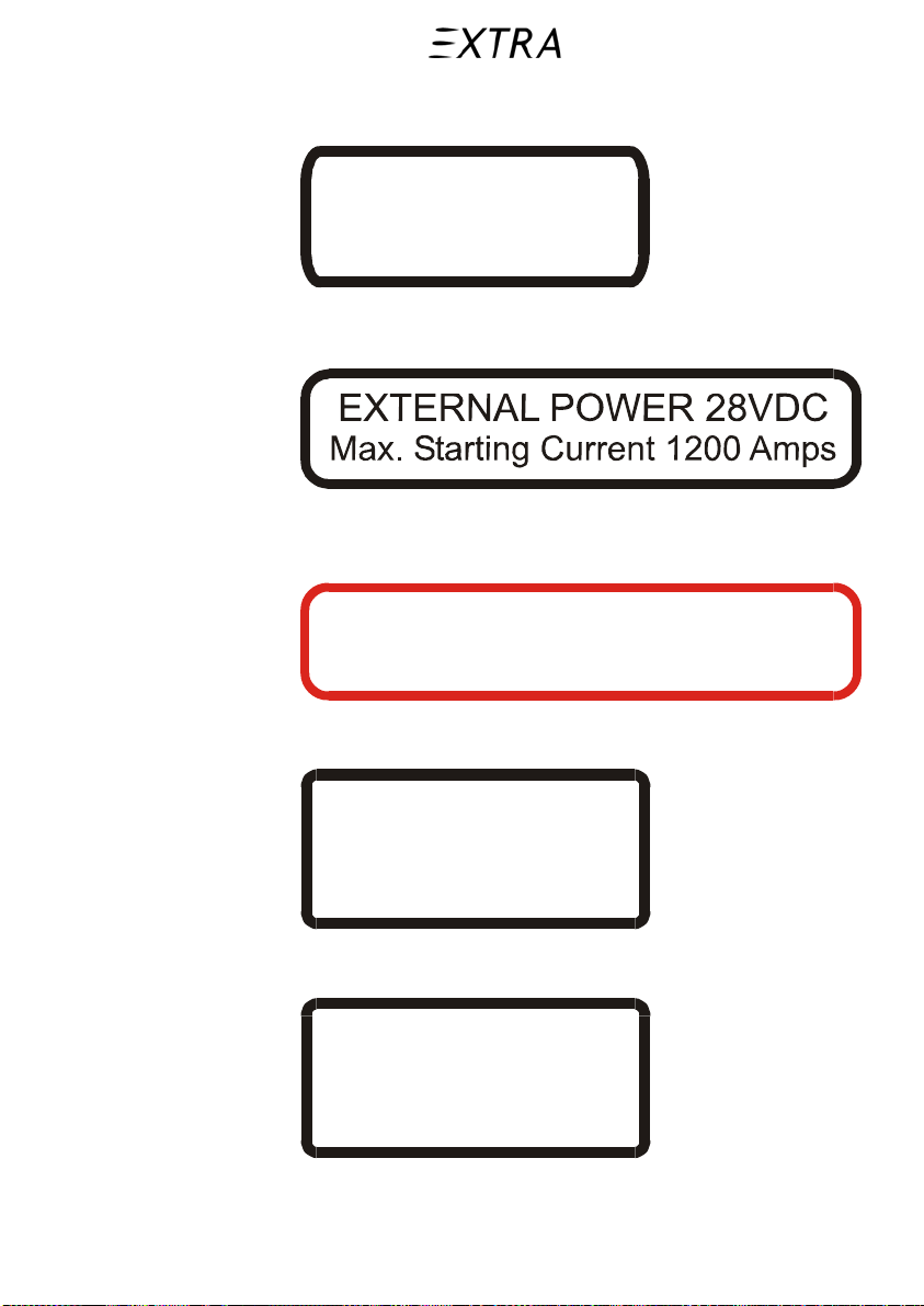
External power access panel (above the oil cooler air outlet,
right fuselage side):
Near the external oil filter indicator (opening in the RH lower
part of the cowling):
OIL FILTER
BYPASS INDICATOR BUTTON
26. January 2011
On the main landing gear oleo shock absorber (LH & RH):
HYDRAULIC FLUID
MIL-H-5606G and
MIL-PRF-5606H or later
57 bar (827 PSI)
On the nose landing gear strut (oleo shock absorber):
HYDRAULIC FLUID
MIL-H-5606G and
MIL-PRF-5606H or later
15 bar (218 PSI)
2-41
Page 66

Section 2 Pilot’s Operating Handbook
Limitations EXTRA 500
On the nose landing gear strut (above swivel stops):
DO NOT EXCEED
NOSE GEAR
MAX
TURNING ANGLE
WHILE TOWING
On the nose landing gear fork:
INFL. PRESS
3.5 bar (51 PSI)
On the main landing gear leg (2x; LH & RH):
INFL. PRESS
5.1 bar (74 PSI)
2-42 26. January 2011
Page 67

Pilot’s Operating Handbook Section 3
EXTRA 500 Emergency Procedures
Section 3
Emergency Procedures
Table of Contents
Paragraph Page
3.1 Introductions.........................................................................................5
3.2 Basic Rules.............................................................................................5
3.3 Used Terms............................................................................................6
3.4 Emergency Procedures Checklist........................................................7
3.4.a Airspeed for safe Operation....................................................................7
3.4.b Airspeed Emergencies.............................................................................7
1 STALL WARN r .......................................................................................7
2 OVERSPEED (aural) ...............................................................................7
3.4.c Engine Malfunctions...............................................................................8
1 Aborted Takeoff......................................................................................8
2 Engine Malfunction during Flight...........................................................8
3 Compressor Stall.....................................................................................9
4 Engine Air Start.....................................................................................10
3.4.d Engine Oil System Malfunctions..........................................................11
1 OIL PRESS r .........................................................................................11
2 CHIP DETECTION y .............................................................................11
3 Abnormal Engine Oil Pressure Indication.............................................11
4 Abnormal High Engine Oil Temperature Indication.............................12
3.4.e Smoke, Fumes and Fire.........................................................................12
1 General Procedure.................................................................................12
2 Engine Fire During Engine Start...........................................................13
3 Engine Fire During Takeoff..................................................................13
4 Engine Fire in Flight .............................................................................13
5 Electrical Fire, Smoke or Fumes in Flight.............................................14
3.4.f Emergency Descent...............................................................................15
3.4.g Maximum Glide....................................................................................15
3.4.h Landing Emergencies............................................................................16
1 Precautionary Landing ..........................................................................16
2 Power Off Landing................................................................................17
3 Wheels Up Landing...............................................................................19
4 Landing with Flat Main Gear Tire ........................................................20
5 Landing with Flat Nose Gear Tire.........................................................22
6 Landing with Defective Main Gear.......................................................23
26. January 2011
3-1
Page 68

Section 3 Pilot’s Operating Handbook
Emergency Procedures EXTRA 500
7 Landing with Flaps Retracted ............................................................... 24
3.4.i Ditching, Power Off/Power On.............................................................25
3.4.j Fuel System Malfunctions .................................................................... 27
1 FUEL PRESS r......................................................................................27
2 FUEL LOW LEFT – FUEL LOW RIGHT y.............................................27
3 FUEL TRANS LEFT – FUEL TRANS RIGHT y.....................................28
4 FUEL FILTER BYPASS y......................................................................28
3.4.k Propeller Malfunctions .........................................................................28
1 LOW PITCH y........................................................................................28
3.4.l Electrical System Malfunctions............................................................29
1 GENERATOR FAIL r.............................................................................29
2 STANDBY ALTERN ON y.....................................................................30
3 LO VOLTAGE y.....................................................................................31
4 Circuit Breaker Tripped........................................................................31
3.4.m Flight Control Malfunctions .................................................................31
1 FLAPS r.................................................................................................31
2 Elevator Control Failure........................................................................32
3 Spins ...................................................................................................33
3.4.n Landing Gear Malfunctions..................................................................34
1 GEAR WARN r (with aural) ..................................................................34
2 GEAR WARN r (without aural and gear retracted)................................34
3 GEAR WARN r (without aural and gear extended) ...............................35
4 HYDRAULIC PUMP y ...........................................................................35
5 No Three Greens...................................................................................35
6 Emergency Extension ...........................................................................36
7 Hydraulic System Reactivation.............................................................36
3.4.o Pressurization System Malfunctions.....................................................37
1 CABIN PRESSURE r ............................................................................37
2 AFT DOOR r..........................................................................................37
3 BLEED OVERTEMP r ........................................................................... 38
4 Impending Skin Panel or Window Malfunction ...................................39
3.4.p Flight into Icing Conditions..................................................................39
1 WINDSHIELD HEAT FAIL r...................................................................39
2 STALL HEAT r.......................................................................................39
3 PILOT HEAT LEFT or RIGHT y ............................................................39
4 STATIC HEAT LEFT or RIGHT y.......................................................... 39
5 PNEUMATIC LOW y ............................................................................. 40
6 Unintentional Flight into Icing Conditions ........................................... 40
7 Windshield Icing...................................................................................40
8 Windshield Fogging..............................................................................41
3.4.q Lightning Strike....................................................................................41
3.4.r Emergency Exit Window Removal ...................................................... 42
3-2 26. January 2011
Page 69

Pilot’s Operating Handbook Section 3
EXTRA 500 Emergency Procedures
3.5 Emergency Procedures (Amplified)..................................................43
3.5.a Airspeed for Safe Operation .................................................................43
3.5.b Airspeed Emergencies...........................................................................43
1 STALL WARN r .....................................................................................43
2 OVERSPEED (aural) .............................................................................43
3.5.c Engine Malfunctions.............................................................................43
1 Aborted Takeoff....................................................................................43
2 Engine Malfunction during Flight.........................................................44
3 Compressor Stall...................................................................................44
4 Engine Air Start.....................................................................................45
3.5.d Engine Oil System Malfunctions..........................................................46
1 OIL PRESS r .........................................................................................46
2 CHIP DETECTION y .............................................................................46
3 Abnormal Engine Oil Pressure Indication.............................................46
4 Abnormal High Engine Oil Temperature Indication.............................47
3.5.e Smoke, Fumes and Fire.........................................................................47
1 General Procedure.................................................................................47
2 Engine Fire During Engine Start...........................................................48
3 Engine Fire During Takeoff..................................................................48
4 Engine Fire in Flight .............................................................................49
5 Electrical Fire, Smoke or Fumes in Flight.............................................49
3.5.f Emergency Descent...............................................................................50
3.5.g Maximum Glide....................................................................................50
3.5.h Landing Emergencies............................................................................51
1 Precautionary Landing ..........................................................................51
2 Power Off Landing................................................................................52
3 Wheels Up Landing...............................................................................52
4 Landing with Flat Main Gear Tire ........................................................54
5 Landing with Flat Nose Gear Tire.........................................................54
6 Landing with Defective Main Gear.......................................................55
7 Landing with Flaps Retracted................................................................56
3.5.i Ditching, Power Off/Power On.............................................................57
3.5.j Fuel System Malfunctions ....................................................................58
1 FUEL PRESS r......................................................................................58
2 FUEL LOW LEFT – FUEL LOW RIGHT y .............................................59
3 FUEL TRANS LEFT – FUEL TRANS RIGHT y .....................................59
4 FUEL FILTER BYPASS y......................................................................60
3.5.k Propeller Malfunctions..........................................................................60
1 LOW PITCH y........................................................................................60
3.5.l Electrical System Malfunctions ............................................................60
1 GENERATOR FAIL r.............................................................................60
2 STANDBY ALTERN ON y .....................................................................61
3 LO VOLTAGE y.....................................................................................62
26. January 2011
3-3
Page 70

Section 3 Pilot’s Operating Handbook
Emergency Procedures EXTRA 500
4 Circuit Breaker Tripped........................................................................62
3.5.m Flight Control Malfunctions .................................................................63
1 FLAPS r.................................................................................................63
2 Elevator Control Failure........................................................................63
3 Spins ...................................................................................................64
3.5.n Landing Gear Malfunctions..................................................................64
1 GEAR WARN r (with aural) ..................................................................64
2 GEAR WARN r (without aural and gear retracted)................................65
3 GEAR WARN r (without aural and gear extended) ...............................65
4 HYDRAULIC PUMP y ...........................................................................65
5 No Three Greens...................................................................................66
6 Emergency Extension ...........................................................................66
7 Hydraulic System Reactivation.............................................................66
3.5.o Pressurization System Malfunctions.....................................................67
1 CABIN PRESSURE r ............................................................................67
2 AFT DOOR r..........................................................................................67
3 BLEED OVERTEMP r ........................................................................... 68
4 Impending Skin Panel or Window Malfunction ...................................68
3.5.p Flight into Icing Conditions..................................................................69
1 WINDSHIELD HEAT FAIL r...................................................................69
2 STALL HEAT r.......................................................................................69
3 PILOT HEAT LEFT or RIGHT y ............................................................69
4 STATIC HEAT LEFT or RIGHT y.......................................................... 69
5 PNEUMATIC LOW y ............................................................................. 70
6 Unintentional Flight into Icing Conditions ........................................... 70
7 Windshield Icing...................................................................................70
8 Windshield Fogging..............................................................................70
3.5.q Lightning Strike....................................................................................70
3.5.r Emergency Exit Window Removal ...................................................... 71
3-4 26. January 2011
Page 71

Pilot’s Operating Handbook Section 3
EXTRA 500 Emergency Procedures
3 Emergency Procedures
3.1 Introductions
General
This Section describes in abbreviated form (checklist) the
procedures for emergency and abnormal situations.
Amplifications to the abbreviated checklist are presented in
addition by subparagraphs to each checklist paragraph e.g.
subparagraph c corresponds to paragraph c etc.
Important The procedures are arranged in the most desirable sequence
for the majority of cases; therefore the steps must be
performed as listed, unless good reasons for deviations can
be determined.
Multiple emergencies, adverse weather and other peculiar
conditions may require modification of these procedures. A
thorough knowledge of the correct procedures and aircraft
systems is essential to analyze the situation correctly and
determine the best course of action.
Special emphasis should be placed and knowing those
procedures or steps for emergency conditions that require
immediate actions.
These procedures are printed in “bold face”.
Important Procedures must be periodically reviewed to maintain
familiarity with procedures.
3.2 Basic Rules
Three basic rules apply to most emergencies and should
therefore be observed in addition:
1 Maintain aircraft control
2 Analyze the situation and take proper action
3 Land as soon as possible/Land as soon as practical
26. January 2011
3-5
Page 72

Section 3 Pilot’s Operating Handbook
Emergency Procedures EXTRA 500
3.3 Used Terms
The terms “Land as soon as possible” and “Land as soon as
practical” are used in this section. The terms are defined as
follows:
“Land as soon as possible” (Land ASAP)
Landing should be accomplished at the nearest suitable field
considering the severity of the emergency.
Further on, weather conditions, if landing on airport is possible,
airport facilities and command guidance and the aircraft gross
weight are to be considered.
“Land as soon as practical”
Emergency conditions are less urgent and in pilot’s/crew
judgment, the flight may be safely continued to an airfield
where more adequate facilities are available and a safe landing
can be accomplished.
Note Refer to section 9 of this handbook for amended operating
limitations, operating procedures, performance data and
other necessary information for aircraft equipped with
specific options.
3-6 26. January 2011
Page 73
Pilot’s Operating Handbook Section 3
EXTRA 500 Emergency Procedures
3.4 Emergency Procedures Checklist
3.4.a Airspeed for safe Operation
Aircraft weight: 2130 kg (4696 lbs)
Speed KIAS
Maneuvering Speed 156
Stall Speed Flaps Up 80
Stall Speed in Landing Configuration 58
Speed for Maximum Gliding Distance 110
Emergency Descent (gear down) 140
Approach Speed for Precautionary Landin g
with Power (Landing Configuration)
Approach Speed without Power
Wing Flaps UP
Wing Flaps DOWN 30°
3.4.b Airspeed Emergencies
80
120
100
26. January 2011
1 STALL WARN r
Item Condition
Control Wheel Push
Power Lever
MAX POWER
2 OVERSPEED (aural)
Item Condition
Control Wheel Pull
Power Lever Reduce power
3-7
Page 74
Section 3 Pilot’s Operating Handbook
Emergency Procedures EXTRA 500
3.4.c Engine Malfunctions
1 Aborted Takeoff
Item Condition
Power Lever
Condition Lever
LANDING GEAR
FLAPS 30°
FLT IDLE
FUEL OFF
Re-check
DN
If all wheels on ground:
Item Condition
Brakes Apply as required
2 Engine Malfunction during Flight
Item Condition
Aircraft Trim for 110 KIAS
Power Lever Minimum required
Condition Lever As required
Engine/Fuel Indications
Monitor to analyze
cause of malfunction
If malfunction cannot be detected and engine power is still
available:
Item Condition
Land as soon as practical
If total mechanical failure has occurred/was detected:
Item Condition
Engine Shut down
Mayday Call Transmit
Transponder
EMERGENCY
Power Off Landing Perform
3-8 26. January 2011
Page 75
Pilot’s Operating Handbook Section 3
EXTRA 500 Emergency Procedures
3 Compressor Stall
Item Condition
Power Lever
FLT IDLE
Condition Lever As required
Angle of Attack Decrease
Airspeed Increase if possible
ENV AIR OFF
If engine stall is recovered:
Item Condition
Power Lever Slowly to desired power
Condition Lever Set as required
Flight Continue
Engine Instruments Monitor
If engine stall cannot be recovered:
Item Condition
Engine Shut down
Engine Air Start Attempt
26. January 2011
3-9
Page 76
Section 3 Pilot’s Operating Handbook
Emergency Procedures EXTRA 500
4 Engine Air Start
Caution Except during an emergency, do not attempt an in-flight
engine restart between 1 and 10 minutes after engine failure
Important Safe engine air start is possible up to 24.000 ft pressure
altitude and at airspeed up to 140 kt TAS.
Item Condition
Airspeed 110 KIAS
FUEL SELECTOR VALVE
FUEL PUMP 1 and 2 Both ON
Condition Lever
BATT
BOTH
Check
FUEL OFF
Check ON
Voltmeter Reading Check reading > 24 V
Power Lever
FLT IDLE
TOT Check reading < 150 °C
ENGINE START
Momentary
START
At 12 % N1:
Item Condition
Condition Lever Fully forward
TOT Monitor < 850 °C
At 58 % N1:
Item Condition
Engine Power Apply Slowly
Engine Instruments Monitor, in the green
If engine air start was successful:
Item Condition
Land as soon as practical
If air start was unsuccessful:
Item Condition
Engine Shut down
Power Off Landing Perform
3-10 26. January 2011
Page 77
Pilot’s Operating Handbook Section 3
EXTRA 500 Emergency Procedures
3.4.d Engine Oil System Malfunctions
1 OIL PRESS r
Item Condition
Oil Pressure Check in limits
If reading exceeds limits:
Item Condition
Power lever
Reduce to minimum power
required to sustain flight
Land as soon as practicable
Important
Be prepared for a possible engine shut down and for a
power off landing.
2 CHIP DETECTION y
Item Condition
Power lever
Reduce to minimum power
required to sustain flight
Land as soon as practicable
Note
Inspect magnetic plugs as soon as possible after landing.
If splinters and/or chips are detected and out of limits,
engine inspection is recommended.
26. January 2011
3 Abnormal Engine Oil Pressure Indication
Item Condition
Engine Oil Pressure Monitor
Engine Instruments Monitor
Land as soon as practical
3-11
Page 78
Section 3 Pilot’s Operating Handbook
Emergency Procedures EXTRA 500
4 Abnormal High Engine Oil Temperature Indication
Item Condition
Airspeed Increase
Land ASAP
3.4.e Smoke, Fumes and Fire
1 General Procedure
Note To provide maximum fresh air turn bleed air off.
Item Condition
Engine Cowling Joints Check for smoke
Cabin Air Smell
Instrument Panels Check for smoke
Dispensers and Vents Check for smoke
Cabin Pressurization System Check and set as required
Cabin Air Adjust as required
If situation requires:
Item Condition
PRESS DUMP
Emergency Descent
Perform
to safe altitude
If smoke is out of control:
Item Condition
Transponder
EMERGENCY
Mayday Call Transmit
Note
Decision to “land as soon as practical” or to “land ASAP”
depends on pilot’s decision after analyzing impairment of
smoke/fumes.
Land as soon as possible/practical
3-12 26. January 2011
Page 79
Pilot’s Operating Handbook Section 3
EXTRA 500 Emergency Procedures
2 Engine Fire During Engine Start
Item Condition
FUEL SELECTOR VALVE OFF
Engine will shut down within 30 seconds.
Item Condition
GEN OFF
STDBY ALT OFF
BATT OFF
If engine fire still persists:
Item Condition
Aircraft Abandon
Fire
Try to extinguish
by external means
3 Engine Fire During Takeoff
Warning It may be necessary to use engine power as long as possible
for safe approach to selected landing site. Sideslip aircraft if
necessary for keeping sight. Nevertheless, in any case try to
shut down engine as soon as possible.
After landing area is selected and safe approach established:
Item Condition
Power Off Landing Perform ASAP
4 Engine Fire in Flight
Warning It may be necessary to use engine power as long as possible
for safe approach to selected landing site. Sideslip aircraft if
necessary for keeping sight. Nevertheless, in any case try to
shut down engine as soon as possible.
After approaching selected landing site:
Item Condition
Power Off Landing Perform ASAP
26. January 2011
3-13
Page 80
Section 3 Pilot’s Operating Handbook
Emergency Procedures EXTRA 500
5 Electrical Fire, Smoke or Fumes in Flight
Note The severity of the electrical fire and the flight conditions
will determine how much of the aircraft electrical systems
will be cut off.
Item Condition
STDBY ALT Check ON
GEN OFF
EMERGENCY ON
BATT OFF
If source is known:
Item Condition
Faulty Equipment
Pull
Circuit Breaker
BATT ON
EMERGENCY OFF
GEN ON
Cabin Ventilation As required
Land as soon as practical
Aircraft
After landing
Abandon
If source is unknown:
Item Condition
Land ASAP
If required:
Item Condition
PRESS DUMP
Transponder
EMERGENCY
Mayday Call Transmit
Emergency Descent Perform to safe altitude
Land ASAP
3-14 26. January 2011
Page 81
Pilot’s Operating Handbook Section 3
EXTRA 500 Emergency Procedures
3.4.f Emergency Descent
Item Condition
Power Lever
FLT IDLE
Condition Lever Fully forward
Airspeed 140 KIAS
LANDING GEAR DN
Mayday Call Transmit
Transponder
EMERGENCY
At safe altitude:
Item Condition
Aircraft Level off
Flight Continue
3.4.g Maximum Glide
Item Condition
LANDING GEAR
FLAPS UP
Condition Lever
Re-check
FUEL OFF/FEATHER
UP
Airspeed 110 KIAS
Glide Rate 1.6 NM per 1000 ft
26. January 2011
3-15
Page 82
Section 3 Pilot’s Operating Handbook
Emergency Procedures EXTRA 500
3.4.h Landing Emergencies
Note If engine power is not available, do not attempt to fly a
procedure turn below 1000 ft AGL!
Procedure turn above 1000 ft AGL under consideration of
the following conditions : Landing Gear UP or DOWN,
flaps 15°, on final 30°, airspeed 100 KIAS, maximum bank
angle 45° to 50°.
1 Precautionary Landing
Note Try to reduce the aircraft weight and thus the stall speed by
reducing fuel quantity as much as possible. If conditions
permit, check selected landing site by overflying and
analyze surface and obstacles for further landing decision.
If runway length is insufficient, and landing into unprepared
area is unavoidable and if above 1000 ft A G L:
Item Condition
Passengers/Crew
Alert,
instruct to cushion faces
Transponder
EMERGENCY
Mayday Call Transmit
Note
If possible and time permits, secure loose object in cabin.
If selected landing area requires gear up landing:
Item Condition
Wheels Up Landing Perform
If selected landing area allows gear down landing (e.g. plain
grass area):
Item Condition
LANDING GEAR DN
During landing approach:
Item Condition
FLAPS 30°
Approach Speed Maintain 80 KIAS
3-16 26. January 2011
Page 83
Pilot’s Operating Handbook Section 3
EXTRA 500 Emergency Procedures
On final:
Item Condition
Seats, Seat Belts and
Adjust
Shoulder Harnesses
Power Lever Set as required
Condition Lever Fully forward
Gear UP/DN Landing
Perform
Keep nose up attitude
as long as possible
Brakes Apply smoothly as necessary
After standstill of aircraft:
Item Condition
Power Lever
Condition Lever
FUEL PUMP 1 and 2
GEN OFF
STDBY ALT OFF
GRD IDLE
FUEL OFF
OFF
Note
If danger of fire is not obvious raise flaps after landing.
FLAPS UP
BATT OFF
Aircraft Abandon
26. January 2011
2 Power Off Landing
Item Condition
Power Lever
Condition Lever
FUEL SELECTOR VALVE OFF
FLT IDLE
FUEL OFF
Approach Speed Maintain 100 KIAS
During landing approach:
Item Condition
FLAPS 15°
3-17
Page 84
Section 3 Pilot’s Operating Handbook
Emergency Procedures EXTRA 500
On final:
Item Condition
Seats, Seat Belts and
Adjust
Shoulder Harnesses
FLAPS 30°
30° flap position light Check illuminated
GEAR IND
Check three greens
Before touch down:
Item Condition
GEN OFF
STDBY ALT OFF
BATT OFF
Warning
Stall warning is not available when electrical system
is switched off.
Landing
Perform
Keep nose up attitude as long
as possible
Brakes Apply smoothly as necessary
After stand still of aircraft:
Item Condition
Note
If danger of fire is not obvious raise flaps after landing.
BATT ON
FLAPS UP
BATT OFF
Aircraft Abandon
3-18 26. January 2011
Page 85
Pilot’s Operating Handbook Section 3
EXTRA 500 Emergency Procedures
3 Wheels Up Landing
If runway length is insufficient, and landing into unprepared
area is unavoidable and if above 1000 ft A G L:
Item Condition
Passengers/Crew
Alert,
instruct to cushion faces
Transponder
EMERGENCY
Mayday Call Transmit
Note
If possible and time permits, secure loose object in cabin.
LANDING GEAR UP
During landing approach:
Item Condition
FLAPS 30°
Approach Speed Maintain 80 KIAS
On final:
Item Condition
Seats, Seat Belts and
Adjust
Shoulder Harnesses
Power Lever Set as required
Condition Lever Fully forward
Gear Up Landing
Perform
Keep nose up attitude
as long as possible
26. January 2011
3-19
Page 86

Section 3 Pilot’s Operating Handbook
Emergency Procedures EXTRA 500
After standstill of aircraft:
Item Condition
Power Lever
Condition Lever
FUEL PUMP 1 and 2
ENGINE START IGN OFF
GEN OFF
STDBY ALT OFF
GRD IDLE
FUEL OFF
OFF
Note
If danger of fire is not obvious raise flaps after landing.
FLAPS UP
BATT OFF
Aircraft Abandon
4 Landing with Flat Main Gear Tire
Caution Do not retract landing gear with blown main gear tire(s)
because blown tire may distort and bind main gear strut(s)
within wheel well and may prevent further gear extension.
Item Condition
LANDING GEAR
FUEL SELECTOR VALVE
Select tank on side of blown
Keep
DN
tire to consume as much as
possible fuel
3-20 26. January 2011
Page 87
Pilot’s Operating Handbook Section 3
EXTRA 500 Emergency Procedures
Short before landing:
Item Condition
FUEL SELECTOR VALVE BOTH
Caution
It is recommended to land aircraft into wind ahead or
crosswind opposite to side of deflated tire.
FLAPS 30°
Landing Approach Perform
Caution
Align aircraft with edge of runway opposite the blown tire,
to have room for a mild turn during landing roll. Land
slightly with wing low on side of inflated tire and hold
aircraft off flat tire as long as possible with aileron control.
Lower nose wheel to ground as soon as possible for
positive steering.
After touch down:
Item Condition
Brakes
Apply brake of inflated tire
smoothly and
maintain directional control
26. January 2011
After aircraft has stopped:
Item Condition
Power Lever
Condition Lever
FUEL PUMP 1 and 2
ENGINE START IGN OFF
GEN OFF
STDBY ALT OFF
GRD IDLE
FUEL OFF
OFF
Note
If danger of fire is not obvious raise flaps after landing.
FLAPS UP
BATT OFF
Aircraft Abandon
3-21
Page 88

Section 3 Pilot’s Operating Handbook
Emergency Procedures EXTRA 500
5 Landing with Flat Nose Gear Tire
Caution Do not retract landing gear with blown main gear tire(s)
because blown tire may distort and bind main gear strut(s)
within wheel well and may prevent further gear extension.
Item Condition
LANDING GEAR
Keep
DN
Aircraft Fuel Consume as much as possible
Approach Normal
Landing Perform
After touchdown of main wheel:
Item Condition
Aircraft Nose
Hold off ground
as long as possible
Brakes
Apply smoothly and steadily
and keep directional control
with differential braking
Control Wheel Full AFT until aircraft stops
After aircraft has stopped:
Item Condition
Power Lever
Condition Lever
FUEL PUMP 1 and 2
ENGINE START IGN OFF
GEN OFF
STDBY ALT OFF
GRD IDLE
FUEL OFF
OFF
Note
If danger of fire is not obvious raise flaps after landing.
FLAPS UP
BATT OFF
Aircraft Abandon
3-22 26. January 2011
Page 89
Pilot’s Operating Handbook Section 3
EXTRA 500 Emergency Procedures
6 Landing with Defective Main Gear
Item Condition
FUEL SELECTOR VALVE
Select tank on side of
defective gear to consume
as much as possible fuel
Short before landing:
Item Condition
FUEL SELECTOR VALVE BOTH
Note
It is recommended to land aircraft into wind ahead or
crosswind opposite to side of defective main gear.
LANDING GEAR DN
FLAPS 30°
Landing Approach Perform
GEN OFF
STDBY ALT OFF
BATT OFF
Important
Stall warning is not available without electrical power.
Caution
Align aircraft with edge of runway opposite the defective
main gear side, to have room for a mild turn during
landing roll. Land with wing low on side of defective main
gear side and hold aircraft off defective main gear as long
as possible with aileron control. Lower nose wheel to
ground as soon as possible for positive steering.
26. January 2011
After touchdown:
Item Condition
Brakes
Apply brake of
operative gear smoothly and
maintain directional control
3-23
Page 90
Section 3 Pilot’s Operating Handbook
Emergency Procedures EXTRA 500
After aircraft has stopped:
Item Condition
Power Lever
Condition Lever
FUEL PUMP 1 and 2
ENGINE START IGN OFF
GEN OFF
STDBY ALT OFF
GRD IDLE
FUEL OFF
OFF
Note
If danger of fire is not obvious raise flaps after landing.
FLAPS UP
BATT OFF
Aircraft Abandon
7 Landing with Flaps Retracted
Important Landing with flaps up differs from normal landing in
respect of the approach speed, stall speed and landing
distance required.
Item Condition
Approach Speed 120 KIAS
LANDING GEAR DN
Caution
Do not overrotate on touchdown.
Tailcone may hit the runway
Note
Stall speed flaps UP is raised to 80 KIAS. Ensure that
runway length is sufficient for landing roll.
Landing Perform
3-24 26. January 2011
Page 91
Pilot’s Operating Handbook Section 3
EXTRA 500 Emergency Procedures
3.4.i Ditching, Power Off/Power On
Important The aircraft has not been flight tested in actual ditching.
Therefore the following recommended procedure is based
entirely on the best judgment available and following
calculations and consideration being made concerning
ditching with respect to the vaulted underside of aircraft
fuselage.
Item Condition
Transponder
EMERGENCY
Mayday Call Transmit
During approach:
Item Condition
PRESS DUMP
Loose and heavy objects
Stow and secure
in cabin
Seat, Seat Belts,
Fasten and secure
Shoulder Harnesses
Passengers/Crew
Alert,
instruct to cushion faces
LANDING GEAR UP
Important
In high wind speeds, aircraft approach should be headed
into wind. In light winds and heavy swells, aircraft
approach should be executed parallel to swells.
26. January 2011
If approach is established:
Item Condition
FLAPS
30° (if possible)
Approach Speed 70 KIAS
Caution
If flap setting 30° is not possible, the following approach
speed are relevant to flap setting:
Flaps 15° = 77 KIAS,
Flaps 0° = 91 KIAS.
3-25
Page 92
Section 3 Pilot’s Operating Handbook
Emergency Procedures EXTRA 500
If power on:
Item Condition
Power Lever Set for sink rate of 300 ft/min
Engine
Prior ditching:
Shut down
Short before ditching:
Item Condition
Airspeed Maintain approach speed
Important
Stall warning is not available without electrical power.
GEN OFF
STDBY ALT OFF
BATT OFF
Ditching
Execute without flare
(in descent attitude)
Important
Immediately after aircraft has alighted on water, try to
retract flaps by using momentarily battery power. This to
make evacuation via main door or emergency window
easier. Nevertheless, if flap retraction is not possible, push
upper door strongly against extended flaps. Flaps edges
are deformable. Be aware, that you have to counteract
outside water pressure by opening the lower door.
BATT ON
FLAPS UP
BATT OFF
Important
Pilot/Crew have to organize aircraft evacuation and
availability of life vests and raft.
Aircraft Abandon
Life Vests and Raft
Inflate when outside cabin
and clear of aircraft
3-26 26. January 2011
Page 93
Pilot’s Operating Handbook Section 3
EXTRA 500 Emergency Procedures
If circumstances permit:
Note Try to close door and/or emergency exit window after
evacuation to keep aircraft afloat as long as possible.
3.4.j Fuel System Malfunctions
1 FUEL PRESS r
Item Condition
Fuel Quantity Check
FUEL SELECTOR VALVE
FUEL PUMP 1 and 2 Both ON
Check
BOTH
If FUEL PRESS extinguishes:
Item Condition
Land as soon as practical
If FUEL PRESS still illuminates:
Item Condition
Power Lever
Reduce
to minimum power required
Warning
Be prepared for a possible engine failure and power off
landing.
Land ASAP
26. January 2011
2 FUEL LOW LEFT – FUEL LOW RIGHT y
Item Condition
Fuel Quantity Relevant
Tank(s)
FUEL SELECTOR VALVE
Switch to not-empty tank
within 5 minutes
Re-check
3-27
Page 94

Section 3 Pilot’s Operating Handbook
Emergency Procedures EXTRA 500
3 FUEL TRANS LEFT – FUEL TRANS RIGHT y
Item Condition
Fuel Quantity Check
FUEL TRANSFER
LEFT
or RIGHT
FUEL-TR-L Circuit Breaker
Re-check
Re-check
ON
IN
or
FUEL-TR-R Circuit Breaker
If light persists:
Item Condition
FUEL TRANSFER
LEFT
or RIGHT
OFF
Note
On the affected tank side:
Unusable fuel increases from 14 L to 32 L.
Auxiliary tank fuel is not available.
FUEL LOW will illuminate on a much earlier stage.
Range
Re-calculate and
change flight plan as required
4 FUEL FILTER BYPASS y
Item Condition
Fuel Pressure Check
Aircraft Fuel Filter Element
Replace
within 2 hours of flight
3.4.k Propeller Malfunctions
1 LOW PITCH y
Item Condition
Power Lever Move forward
Note In case of propeller problems e.g. oil pressure loss etc.,
propeller feathering is accomplished by the condition lever
set to “FEATHER” position.
3-28 26. January 2011
Page 95
Pilot’s Operating Handbook Section 3
EXTRA 500 Emergency Procedures
3.4.l Electrical System Malfunctions
Note In case of a generator failure, the load bus will be
automatically shed.
1 GENERATOR FAIL r
Item Condition
GEN
RESET
(hold for approx. 2 seconds
and back to
ON)
If GENERATOR FAIL extinguishes:
Item Condition
VDC
GEN AMPS
Check 28
Check indication
Flight Continue
If GENERATOR FAIL still illuminates:
Item Condition
AVIONICS OFF
Flight Leave icing conditions
ICE OFF
PROP OFF
BOOTS OFF
WINDSH OFF
ENGINE START IGN OFF
STANDBY ALTERN ON
Check illuminated
no specific procedure required
Note
Battery and standby alternator supply is limited to at least
30 minutes.
26. January 2011
In case a load from the load bus is necessary:
Item Condition
All load bus Circuit Breakers Pull
Needed Circuit Breakers Push in
BUS TIE Circuit Breaker Push in
3-29
Page 96
Section 3 Pilot’s Operating Handbook
Emergency Procedures EXTRA 500
If a landing is possible within 30 minutes:
Item Condition
Land ASAP
If a landing is not possible within 30 minutes
Item Condition
FUEL PUMP 1 ON
Flight Descent to 10,000ft
EMERGENCY ON
Notes
Aircraft functionality will be limited to a minimum
(only loads of emergency bus).
Landing gear will slowly extend. Flaps cannot be moved.
Unusable fuel increases from 14 L to 32 L per side.
Auxiliary compartment fuel is not available.
FUEL LOW will illuminate on a much earlier stage.
Range
Re-calculate and
change flight plan as required
If within 30 minutes of airfield
Item Condition
EMERGENCY OFF
Land ASAP
2 STANDBY ALTERN ON y
Item Condition
GENERATOR FAIL
Check illuminated
If GENERATOR FAIL illuminates:
Item Condition
GENERATOR FAIL
Perform
Procedure
If GENERATOR FAIL not illuminates:
Item Condition
VDC
Check > 26.5
3-30 26. January 2011
Page 97
Pilot’s Operating Handbook Section 3
EXTRA 500 Emergency Procedures
If voltage is above 26.5VDC
Item Condition
STDBY ALT OFF
3 LO VOLTAGE y
Item Condition
VDC
Check > 25.5
In case voltage is below 25.5VDC:
Item Condition
GEN AMPS
Check approx. 20
In case indication is significantly below:
Item Condition
Caution
Do not exceed engine and airspeed limits
Power Lever Slightly forward
4 Circuit Breaker Tripped
Item Condition
Circuit Breaker
If circuit breaker trips again:
Item Condition
Circuit Breaker Leave tripped
Flight Continue
3.4.m Flight Control Malfunctions
1 FLAPS r
Item Condition
Balance Aircraft
Land ASAP
26. January 2011
Only one attempt:
Push in
Slightly by using rudder
and/or aileron
3-31
Page 98
Section 3 Pilot’s Operating Handbook
Emergency Procedures EXTRA 500
During landing approach:
Item Condition
Flaps position Estimate position
Landing Approach Speed
Due to estimated flap position
between
Flaps 30° = 80 KIAS
Flaps UP = 120 KIAS
LANDING GEAR
Power Lever
Landing
DN
Set as required
Perform
2 Elevator Control Failure
Item Condition
Pitch Control Use aircraft trim
Mayday Call Transmit
Note
For landing, select long runwa y with
possibly low crosswinds.
Landing Approach Long Final
Note
Landing gear and flaps should be set down
as early as possible to stabilize drag during approach.
LANDING GEAR DN
FLAPS
30°
Aircraft Trim full aft
Power Lever Set as required
Approximately 20 feet AGL:
Item Condition
Power Lever
Set as required to obtain nose
up attitude
Landing Perform
3-32 26. January 2011
Page 99
Pilot’s Operating Handbook Section 3
EXTRA 500 Emergency Procedures
3 Spins
Note Spins are not permitted with this aircraft.
If the aircraft unintentionally comes into a spin, the recovery
procedure is as follows:
Item Condition
Power Lever
Rudder
FLT IDLE
Full opposite to
rotation direction
Ailerons Neutral
Elevator Forward
If flaps were set:
Item Condition
FLAPS UP
When rotation has stopped:
Item Condition
Rudder Neutral
Elevator Pull
Aircraft Level off
Flight Continue
26. January 2011
3-33
Page 100
Section 3 Pilot’s Operating Handbook
Emergency Procedures EXTRA 500
3.4.n Landing Gear Malfunctions
Note If there is any doubt about condition of landing gear, it is
preferable to perform a fly by in conjunction with ground
station e.g. tower etc.
Note If prolonged flight with extended landing gear is necessary,
consider reduced cruise speed.
1 GEAR WARN r (with aural)
When in approach:
Item Condition
Airspeed Reduce below 140KIAS
LANDING GEAR DN
Else:
Item Condition
Power Lever
move forward until
torque above 35%
LANDING GEAR DN
2 GEAR WARN r (without aural and gear retracted)
Item Condition
Airspeed Reduce below 140KIAS
LANDING GEAR
HYDR Circuit Breaker Check in
GEAR-CTRL Circuit Breaker Check in
Check UP
Hydraulic Pump Runs periodically
If GEAR WARN still illuminated:
Caution Do not attempt to retract landing gear further if it fails to
retract during first attempt.
Item Condition
LANDING GEAR DN
Land as soon as practical
3-34 26. January 2011
 Loading...