

Page 1
MAINTENANCE MANUAL
EXTRA 300LT
Doc. No: EA-0D702
EXTRA
FLUGZEUGPRODUKTIONS-
UND VERTRIEBS-GMBH
Schwarze Heide 21
D-46569 Hünxe, Germany
Tel: 49-28 58-91 37-0
Fax: 49-28 58-91 37-30
Page 2

MAINTENANCE MANUAL EXTRA 300L T
Log of Revisions
Dates of issue for original and revised pages:
1st Edition (Chapter 4 & 5 only)............. 30. April 2010
2nd Edition
(Complete Manual except Chapter 4) ........ 7. July 2010
Date and sign of approval:
EASA MAJOR CHANGE APPROV AL
N° 10030180.............................................. 1. June 2010
Approved under the authority of DOA
N° EASA.21J.073 .......................... 18. November 2010
P AGE DA TE: 7. July 2010
PAGE A
Page 3
MAINTENANCE MANUAL EXTRA 300L T
Log of Effective Pages
Date of IssueChapter Page
Cover sheet 7. July 2010
A 7. July 2010
B 7. July 2010
C 7. July 2010
D 7. July 2010
E 7. July 2010
F 7. July 2010
G 7. July 2010
H 7. July 2010
1 1 7. July 2010
2 7. July 2010
3 7. July 2010
4 7. July 2010
5 7. July 2010
6 7. July 2010
7 7. July 2010
2 1 7. July 2010
2 7. July 2010
3 7. July 2010
4 7. July 2010
5 7. July 2010
6 7. July 2010
7 7. July 2010
8 7. July 2010
9 7. July 2010
3 1 7. July 2010
2 7. July 2010
3 7. July 2010
4 7. July 2010
5 7. July 2010
6 7. July 2010
7 7. July 2010
4 1 30. April 2010
2 30. April 2010
3 30. April 2010
4 30. April 2010
5 30. April 2010
6 30. April 2010
7 30. April 2010
5 1 7. July 2010
2 7. July 2010
3 7. July 2010
4 7. July 2010
5 7. July 2010
6 7. July 2010
7 7. July 2010
8 7. July 2010
9 7. July 2010
1 0 7. July 2010
1 1 7. July 2010
1 2 7. July 2010
1 3 7. July 2010
1 4 7. July 2010
Date of IssueChapter Page
1 5 7. July 2010
1 6 7. July 2010
1 7 7. July 2010
1 8 7. July 2010
1 9 7. July 2010
2 0 7. July 2010
2 1 7. July 2010
2 2 7. July 2010
2 3 7. July 2010
2 4 7. July 2010
2 5 7. July 2010
2 6 7. July 2010
2 7 7. July 2010
2 8 7. July 2010
2 9 7. July 2010
3 0 7. July 2010
3 1 7. July 2010
3 2 7. July 2010
3 3 7. July 2010
3 4 7. July 2010
3 5 7. July 2010
3 6 7. July 2010
3 7 7. July 2010
3 8 7. July 2010
3 9 7. July 2010
4 0 7. July 2010
6 1 7. July 2010
2 7. July 2010
3 7. July 2010
4 7. July 2010
5 7. July 2010
6 7. July 2010
7 1 7. July 2010
2 7. July 2010
3 7. July 2010
4 7. July 2010
5 7. July 2010
8 1 7. July 2010
2 7. July 2010
3 7. July 2010
4 7. July 2010
5 7. July 2010
6 7. July 2010
7 7. July 2010
9 1 7. July 2010
2 7. July 2010
3 7. July 2010
4 7. July 2010
1 0 1 7. July 2010
2 7. July 2010
3 7. July 2010
4 7. July 2010
5 7. July 2010
Date of IssueChapter Page
6 7. July 2010
1 2 1 7. July 2010
2 7. July 2010
3 7. July 2010
4 7. July 2010
5 7. July 2010
6 7. July 2010
7 7. July 2010
8 7. July 2010
9 7. July 2010
1 0 7. July 2010
1 1 7. July 2010
1 2 7. July 2010
1 3 7. July 2010
1 4 7. July 2010
1 5 7. July 2010
1 6 7. July 2010
1 7 7. July 2010
2 0 1 7. July 2010
2 7. July 2010
3 7. July 2010
4 7. July 2010
5 7. July 2010
6 7. July 2010
7 7. July 2010
8 7. July 2010
9 7. July 2010
1 0 7. July 2010
1 1 7. July 2010
1 2 7. July 2010
1 3 7. July 2010
1 4 7. July 2010
1 5 7. July 2010
1 6 7. July 2010
1 7 7. July 2010
1 8 7. July 2010
2 1 1 7. July 2010
2 7. July 2010
3 7. July 2010
4 7. July 2010
5 7. July 2010
6 7. July 2010
7 7. July 2010
8 7. July 2010
9 7. July 2010
1 0 7. July 2010
1 1 7. July 2010
2 3 1 7. July 2010
2 7. July 2010
3 7. July 2010
4 7. July 2010
2 4 1 7. July 2010
2 7. July 2010
P AGE DA TE: 7. July 2010
PAGE B
Page 4
MAINTENANCE MANUAL EXTRA 300L T
Log of Effective Pages
Date of IssueChapter Page
3 7. July 2010
4 7. July 2010
5 7. July 2010
6 7. July 2010
7 7. July 2010
8 7. July 2010
9 7. July 2010
1 0 7. July 2010
1 1 7. July 2010
1 2 7. July 2010
1 3 7. July 2010
1 4 7. July 2010
1 5 7. July 2010
2 5 1 7. July 2010
2 7. July 2010
3 7. July 2010
4 7. July 2010
5 7. July 2010
6 7. July 2010
7 7. July 2010
2 7 1 7. July 2010
2 7. July 2010
3 7. July 2010
4 7. July 2010
5 7. July 2010
6 7. July 2010
7 7. July 2010
8 7. July 2010
9 7. July 2010
1 0 7. July 2010
1 1 7. July 2010
1 2 7. July 2010
1 3 7. July 2010
1 4 7. July 2010
1 5 7. July 2010
1 6 7. July 2010
1 7 7. July 2010
1 8 7. July 2010
1 9 7. July 2010
2 0 7. July 2010
2 1 7. July 2010
2 2 7. July 2010
2 3 7. July 2010
2 4 7. July 2010
2 5 7. July 2010
2 6 7. July 2010
2 7 7. July 2010
2 8 7. July 2010
2 8 1 7. July 2010
2 7. July 2010
3 7. July 2010
4 7. July 2010
5 7. July 2010
Date of IssueChapter Page
6 7. July 2010
7 7. July 2010
8 7. July 2010
9 7. July 2010
1 0 7. July 2010
1 1 7. July 2010
1 2 7. July 2010
1 3 7. July 2010
1 4 7. July 2010
1 5 7. July 2010
1 6 7. July 2010
1 7 7. July 2010
1 8 7. July 2010
1 9 7. July 2010
2 0 7. July 2010
2 1 7. July 2010
2 2 7. July 2010
2 3 7. July 2010
2 4 7. July 2010
2 5 7. July 2010
2 6 7. July 2010
2 7 7. July 2010
2 8 7. July 2010
3 1 1 7. July 2010
2 7. July 2010
3 7. July 2010
4 7. July 2010
5 7. July 2010
6 7. July 2010
7 7. July 2010
8 7. July 2010
9 7. July 2010
1 0 7. July 2010
1 1 7. July 2010
3 2 1 7. July 2010
2 7. July 2010
3 7. July 2010
4 7. July 2010
5 7. July 2010
6 7. July 2010
7 7. July 2010
8 7. July 2010
9 7. July 2010
1 0 7. July 2010
1 1 7. July 2010
1 2 7. July 2010
3 3 1 7. July 2010
2 7. July 2010
3 7. July 2010
4 7. July 2010
5 7. July 2010
6 7. July 2010
7 7. July 2010
Date of IssueChapter Page
8 7. July 2010
9 7. July 2010
1 0 7. July 2010
3 4 1 7. July 2010
2 7. July 2010
3 7. July 2010
4 7. July 2010
5 7. July 2010
6 7. July 2010
7 7. July 2010
8 7. July 2010
9 7. July 2010
1 0 7. July 2010
5 1 1 7. July 2010
2 7. July 2010
3 7. July 2010
4 7. July 2010
5 7. July 2010
6 7. July 2010
7 7. July 2010
8 7. July 2010
9 7. July 2010
1 0 7. July 2010
1 1 7. July 2010
1 2 7. July 2010
1 3 7. July 2010
1 4 7. July 2010
1 5 7. July 2010
1 6 7. July 2010
1 7 7. July 2010
1 8 7. July 2010
1 9 7. July 2010
2 0 7. July 2010
2 1 7. July 2010
2 2 7. July 2010
2 3 7. July 2010
2 4 7. July 2010
2 5 7. July 2010
2 6 7. July 2010
2 7 7. July 2010
2 8 7. July 2010
2 9 7. July 2010
3 0 7. July 2010
3 1 7. July 2010
3 2 7. July 2010
3 3 7. July 2010
3 4 7. July 2010
3 5 7. July 2010
3 6 7. July 2010
3 7 7. July 2010
5 3 1 7. July 2010
2 7. July 2010
3 7. July 2010
P AGE DA TE: 7. July 2010
PAGE C
Page 5
MAINTENANCE MANUAL EXTRA 300L T
Log of Effective Pages
Date of IssueChapter Page
4 7. July 2010
5 7. July 2010
6 7. July 2010
7 7. July 2010
8 7. July 2010
9 7. July 2010
1 0 7. July 2010
1 1 7. July 2010
1 2 7. July 2010
1 3 7. July 2010
1 4 7. July 2010
1 5 7. July 2010
1 6 7. July 2010
1 7 7. July 2010
5 5 1 7. July 2010
2 7. July 2010
3 7. July 2010
4 7. July 2010
5 7. July 2010
6 7. July 2010
7 7. July 2010
8 7. July 2010
9 7. July 2010
1 0 7. July 2010
1 1 7. July 2010
5 7 1 7. July 2010
2 7. July 2010
3 7. July 2010
4 7. July 2010
5 7. July 2010
6 7. July 2010
7 7. July 2010
8 7. July 2010
9 7. July 2010
1 0 7. July 2010
1 1 7. July 2010
1 2 7. July 2010
6 1 1 7. July 2010
2 7. July 2010
3 7. July 2010
4 7. July 2010
5 7. July 2010
6 7. July 2010
7 7. July 2010
8 7. July 2010
9 7. July 2010
7 1 1 7. July 2010
2 7. July 2010
3 7. July 2010
4 7. July 2010
5 7. July 2010
6 7. July 2010
7 7. July 2010
Date of IssueChapter Page
8 7. July 2010
9 7. July 2010
1 0 7. July 2010
7 2 1 7. July 2010
2 7. July 2010
3 7. July 2010
4 7. July 2010
5 7. July 2010
6 7. July 2010
7 7. July 2010
8 7. July 2010
7 3 1 7. July 2010
2 7. July 2010
3 7. July 2010
4 7. July 2010
5 7. July 2010
6 7. July 2010
7 7. July 2010
8 7. July 2010
9 7. July 2010
1 0 7. July 2010
1 1 7. July 2010
1 2 7. July 2010
1 3 7. July 2010
1 4 7. July 2010
1 5 7. July 2010
7 7 1 7. July 2010
2 7. July 2010
3 7. July 2010
4 7. July 2010
5 7. July 2010
6 7. July 2010
7 7. July 2010
8 7. July 2010
9 7. July 2010
1 0 7. July 2010
1 1 7. July 2010
1 2 7. July 2010
1 3 7. July 2010
1 4 7. July 2010
1 5 7. July 2010
1 6 7. July 2010
7 8 1 7. July 2010
2 7. July 2010
3 7. July 2010
4 7. July 2010
5 7. July 2010
6 7. July 2010
7 7. July 2010
7 9 1 7. July 2010
2 7. July 2010
3 7. July 2010
4 7. July 2010
Date of IssueChapter Page
5 7. July 2010
6 7. July 2010
7 7. July 2010
8 7. July 2010
9 7. July 2010
1 0 7. July 2010
1 1 7. July 2010
1 2 7. July 2010
P AGE DA TE: 7. July 2010
PAGE D
Page 6

MAINTENANCE MANUAL EXTRA 300L T
List of Service Bulletins/Service Letters
S.B./S.L. N°
Issue
Date
Subject
Serial N°
affected
Ge rman AD
(LTA)
P AGE DA TE: 7. July 2010
PAGE E
Page 7

MAINTENANCE MANUAL EXTRA 300L T
CONTENTS
Title Page
Log of Revisions
Log of Effective Pages
List of Service Bulletins/Service Letters
Contents
. . . . . . . . . . . . . . . . . . . . . . . . . . . . . . . . . . . . . . . . . . . . . . . . . . . . . . . . . . . . . . . . . . . . . . . . . . . . . . . . . . . . . . . . . . . . . . . . . . . . . . . . . . . . . . . . . . . . . . . . . . . . . . . . . . . . . . . . . . . . . . . . . . . . . . . . . . . . . . . . . . . . . . . . . . . . . . . . . . . . . . . . . . . . . . . . F-G
Fax Format
. . . . . . . . . . . . . . . . . . . . . . . . . . . . . . . . . . . . . . . . . . . . . . . . . . . . . . . . . . . . . . . . . . . . . . . . . . . . . . . . . . . . . . . . . . . . . . . . . . . . . . . . . . . . . . . . . . . . . . . . . . . . . . . . . . . . . . . . . . . . . . . . . . . . . . . . . . . . . . . . . . . . . . . . . . . . . . . . . A
. . . . . . . . . . . . . . . . . . . . . . . . . . . . . . . . . . . . . . . . . . . . . . . . . . . . . . . . . . . . . . . . . . . . . . . . . . . . . . . . . . . . . . . . . . . . . . . . . . . . . . . . . . . . . . . . . . . . . . . . . . . . . . . . . . . . . . . . . . . . . . . . . . . . . . . . . . . B-D
. . . . . . . . . . . . . . . . . . . . . . . . . . . . . . . . . . . . . . . . . . . . . . . . . . . . . . . . . . . . . . . . . . . . . . . . . . . . . . . . . . . . . . . . . . . . . . . . . . . . . . . . . . . . . . . . . . . . . E
. . . . . . . . . . . . . . . . . . . . . . . . . . . . . . . . . . . . . . . . . . . . . . . . . . . . . . . . . . . . . . . . . . . . . . . . . . . . . . . . . . . . . . . . . . . . . . . . . . . . . . . . . . . . . . . . . . . . . . . . . . . . . . . . . . . . . . . . . . . . . . . . . . . . . . . . . . . . . . . . . . . . . . . . . . . . . . . . . . . . . . . . . . . . . . . H
Group/Chapter title Chapter
GENERAL
Introduction
How to Use the Service Manual
. . . . . . . . . . . . . . . . . . . . . . . . . . . . . . . . . . . . . . . . . . . . . . . . . . . . . . . . . . . . . . . . . . . . . . . . . . . . . . . . . . . . . . . . . . . . . . . . . . . . . . . . . . . . . . . . . . . . . . . . . . . . . . . . . . . . . . . . . . . . . . . . . . . . . . . . . . . . . . . . . . . . . . . . . . . . . . . . . . . . . . . . . . . . . 1
. . . . . . . . . . . . . . . . . . . . . . . . . . . . . . . . . . . . . . . . . . . . . . . . . . . . . . . . . . . . . . . . . . . . . . . . . . . . . . . . . . . . . . . . . . . . . . . . . . . . . . . . . . . . . . . . . . . . . . . . . . . . . . . . . . . . . . . . . . . . 2
AIRCRAFT
General Description
Airworthiness Limitations
Time Limits/Maintenance Checks
Dimensions and Areas
Lifting and Shoring
Levelling and W eighing
T owing and T axiing
Parking, Mooring, Storage and Return to Service
Servicing
. . . . . . . . . . . . . . . . . . . . . . . . . . . . . . . . . . . . . . . . . . . . . . . . . . . . . . . . . . . . . . . . . . . . . . . . . . . . . . . . . . . . . . . . . . . . . . . . . . . . . . . . . . . . . . . . . . . . . . . . . . . . . . . . . . . . . . . . . . . . . . . . . . . . . . . . . . . . . . . . . . . . . . . . . . . . . . . . . . . . . . . . . . . . . . . . . . 12
. . . . . . . . . . . . . . . . . . . . . . . . . . . . . . . . . . . . . . . . . . . . . . . . . . . . . . . . . . . . . . . . . . . . . . . . . . . . . . . . . . . . . . . . . . . . . . . . . . . . . . . . . . . . . . . . . . . . . . . . . . . . . . . . . . . . . . . . . . . . . . . . . . . . . . . . . . . . . . . . . . . . . . . . . 3
. . . . . . . . . . . . . . . . . . . . . . . . . . . . . . . . . . . . . . . . . . . . . . . . . . . . . . . . . . . . . . . . . . . . . . . . . . . . . . . . . . . . . . . . . . . . . . . . . . . . . . . . . . . . . . . . . . . . . . . . . . . . . . . . . . . . . . . . . . . . . . . . . . . . . . . . . . 4
. . . . . . . . . . . . . . . . . . . . . . . . . . . . . . . . . . . . . . . . . . . . . . . . . . . . . . . . . . . . . . . . . . . . . . . . . . . . . . . . . . . . . . . . . . . . . . . . . . . . . . . . . . . . . . . . . . . . . . . . . . . . . . . . . . . . . . 5
. . . . . . . . . . . . . . . . . . . . . . . . . . . . . . . . . . . . . . . . . . . . . . . . . . . . . . . . . . . . . . . . . . . . . . . . . . . . . . . . . . . . . . . . . . . . . . . . . . . . . . . . . . . . . . . . . . . . . . . . . . . . . . . . . . . . . . . . . . . . . . . . . . . . . . . . . . . . . . . . . . . . 6
. . . . . . . . . . . . . . . . . . . . . . . . . . . . . . . . . . . . . . . . . . . . . . . . . . . . . . . . . . . . . . . . . . . . . . . . . . . . . . . . . . . . . . . . . . . . . . . . . . . . . . . . . . . . . . . . . . . . . . . . . . . . . . . . . . . . . . . . . . . . . . . . . . . . . . . . . . . . . . . . . . . . . . . . . . . . 7
. . . . . . . . . . . . . . . . . . . . . . . . . . . . . . . . . . . . . . . . . . . . . . . . . . . . . . . . . . . . . . . . . . . . . . . . . . . . . . . . . . . . . . . . . . . . . . . . . . . . . . . . . . . . . . . . . . . . . . . . . . . . . . . . . . . . . . . . . . . . . . . . . . . . . . . . . . . . . . . . . 8
. . . . . . . . . . . . . . . . . . . . . . . . . . . . . . . . . . . . . . . . . . . . . . . . . . . . . . . . . . . . . . . . . . . . . . . . . . . . . . . . . . . . . . . . . . . . . . . . . . . . . . . . . . . . . . . . . . . . . . . . . . . . . . . . . . . . . . . . . . . . . . . . . . . . . . . . . . . . . . . . . . . . . . . . . . . . . 9
. . . . . . . . . . . . . . . . . . . . . . . . . . . . . . . . . . . . . . . . . . . . . . . . . . . . . . . . . . . . . . . . . . . . . . . . . . . . . . . . . . . . . . . . . . . . . . 10
AIRFRAME SYSTEMS
Standard Practices - Airframe
Air Conditioning
Communications
Electrical Power
. . . . . . . . . . . . . . . . . . . . . . . . . . . . . . . . . . . . . . . . . . . . . . . . . . . . . . . . . . . . . . . . . . . . . . . . . . . . . . . . . . . . . . . . . . . . . . . . . . . . . . . . . . . . . . . . . . . . . . . . . . . . . . . . . . . . . . . . . . . . . . . . . . . . . . . . . . . . . . . . . . . . . . . . . . . . . . . 21
. . . . . . . . . . . . . . . . . . . . . . . . . . . . . . . . . . . . . . . . . . . . . . . . . . . . . . . . . . . . . . . . . . . . . . . . . . . . . . . . . . . . . . . . . . . . . . . . . . . . . . . . . . . . . . . . . . . . . . . . . . . . . . . . . . . . . . . . . . . . . . . . . . . . . . . . . . . . . . . . . . . . . . . . . . . . . . 23
. . . . . . . . . . . . . . . . . . . . . . . . . . . . . . . . . . . . . . . . . . . . . . . . . . . . . . . . . . . . . . . . . . . . . . . . . . . . . . . . . . . . . . . . . . . . . . . . . . . . . . . . . . . . . . . . . . . . . . . . . . . . . . . . . . . . . . . . . . . . . . . . . . . . . . . . . . . . . . . . . . . . . . . . . . . . . . . 24
Equipment/Furnishings
Flight Controls
Fuel
. . . . . . . . . . . . . . . . . . . . . . . . . . . . . . . . . . . . . . . . . . . . . . . . . . . . . . . . . . . . . . . . . . . . . . . . . . . . . . . . . . . . . . . . . . . . . . . . . . . . . . . . . . . . . . . . . . . . . . . . . . . . . . . . . . . . . . . . . . . . . . . . . . . . . . . . . . . . . . . . . . . . . . . . . . . . . . . . . . . . . . . . . . . . . . . . . . . . . . . . . . . . . . . 28
. . . . . . . . . . . . . . . . . . . . . . . . . . . . . . . . . . . . . . . . . . . . . . . . . . . . . . . . . . . . . . . . . . . . . . . . . . . . . . . . . . . . . . . . . . . . . . . . . . . . . . . . . . . . . . . . . . . . . . . . . . . . . . . . . . . . . . . . . . . . . . . . . . . . . . . . . . . . . . . . . . . . . . . . . . . . . . . . . . . 27
Indication/Recording Systems
Landing Gear
Lights
. . . . . . . . . . . . . . . . . . . . . . . . . . . . . . . . . . . . . . . . . . . . . . . . . . . . . . . . . . . . . . . . . . . . . . . . . . . . . . . . . . . . . . . . . . . . . . . . . . . . . . . . . . . . . . . . . . . . . . . . . . . . . . . . . . . . . . . . . . . . . . . . . . . . . . . . . . . . . . . . . . . . . . . . . . . . . . . . . . . . . . . . . . . . . . . . . . . . . . . . . . 33
Navigation
P AGE DA TE: 7. July 2010
. . . . . . . . . . . . . . . . . . . . . . . . . . . . . . . . . . . . . . . . . . . . . . . . . . . . . . . . . . . . . . . . . . . . . . . . . . . . . . . . . . . . . . . . . . . . . . . . . . . . . . . . . . . . . . . . . . . . . . . . . . . . . . . . . . . . . . . . . . . . . . . . . . . . . . . . . . . . . . . . . . . . . . . . . . . . . . . . . . . . . . . . 32
. . . . . . . . . . . . . . . . . . . . . . . . . . . . . . . . . . . . . . . . . . . . . . . . . . . . . . . . . . . . . . . . . . . . . . . . . . . . . . . . . . . . . . . . . . . . . . . . . . . . . . . . . . . . . . . . . . . . . . . . . . . . . . . . . . . . . . . . . . . . . . . . . . . . . . . . . . . . . . . . . . . . . . . . . . . . . . . . . . . . . . . . . . . . . . . 34
. . . . . . . . . . . . . . . . . . . . . . . . . . . . . . . . . . . . . . . . . . . . . . . . . . . . . . . . . . . . . . . . . . . . . . . . . . . . . . . . . . . . . . . . . . . . . . . . . . . . . . . . . . . . . . . . . . . . . . . . . . . . . . . . . . . . . . . . . . . . . . . 20
. . . . . . . . . . . . . . . . . . . . . . . . . . . . . . . . . . . . . . . . . . . . . . . . . . . . . . . . . . . . . . . . . . . . . . . . . . . . . . . . . . . . . . . . . . . . . . . . . . . . . . . . . . . . . . . . . . . . . . . . . . . . . . . . . . . . . . . . . . . . . . . . . . . . . . . . . . . . . . 25
. . . . . . . . . . . . . . . . . . . . . . . . . . . . . . . . . . . . . . . . . . . . . . . . . . . . . . . . . . . . . . . . . . . . . . . . . . . . . . . . . . . . . . . . . . . . . . . . . . . . . . . . . . . . . . . . . . . . . . . . . . . . . . . . . . . . . . . . . . . . 31
PAGE F
Page 8

MAINTENANCE MANUAL EXTRA 300L T
STRUCTURES
CONTENTS
Standard Practices and Structures - General
Fuselage
Stabilizers
Wings
. . . . . . . . . . . . . . . . . . . . . . . . . . . . . . . . . . . . . . . . . . . . . . . . . . . . . . . . . . . . . . . . . . . . . . . . . . . . . . . . . . . . . . . . . . . . . . . . . . . . . . . . . . . . . . . . . . . . . . . . . . . . . . . . . . . . . . . . . . . . . . . . . . . . . . . . . . . . . . . . . . . . . . . . . . . . . . . . . . . . . . . . . . . . . . . . . . . 53
. . . . . . . . . . . . . . . . . . . . . . . . . . . . . . . . . . . . . . . . . . . . . . . . . . . . . . . . . . . . . . . . . . . . . . . . . . . . . . . . . . . . . . . . . . . . . . . . . . . . . . . . . . . . . . . . . . . . . . . . . . . . . . . . . . . . . . . . . . . . . . . . . . . . . . . . . . . . . . . . . . . . . . . . . . . . . . . . . . . . . . . . . . . . . . . 55
. . . . . . . . . . . . . . . . . . . . . . . . . . . . . . . . . . . . . . . . . . . . . . . . . . . . . . . . . . . . . . . . . . . . . . . . . . . . . . . . . . . . . . . . . . . . . . . . . . . . . . . . . . . . . . . . . . . . . . . . . . . . . . . . . . . . . . . . . . . . . . . . . . . . . . . . . . . . . . . . . . . . . . . . . . . . . . . . . . . . . . . . . . . . . . . . . . . . . . . . . . 57
. . . . . . . . . . . . . . . . . . . . . . . . . . . . . . . . . . . . . . . . . . . . . . . . . . . . . . . . . . . . . . . . . . . . . . . . . . . . . . . . . . . . . . . . . . . . . . . . . . . . . . . . . . . 51
PROPELLER
Propeller
. . . . . . . . . . . . . . . . . . . . . . . . . . . . . . . . . . . . . . . . . . . . . . . . . . . . . . . . . . . . . . . . . . . . . . . . . . . . . . . . . . . . . . . . . . . . . . . . . . . . . . . . . . . . . . . . . . . . . . . . . . . . . . . . . . . . . . . . . . . . . . . . . . . . . . . . . . . . . . . . . . . . . . . . . . . . . . . . . . . . . . . . . . . . . . . . . . 61
POWER PLANT
Power Plant
Engine
Engine Fuel and Control
Engine Indicating
Exhaust
System. . . . . . . . . . . . . . . . . . . . . . . . . . . . . . . . . . . . . . . . . . . . . . . . . . . . . . . . . . . . . . . . . . . . . . . . . . . . . . . . . . . . . . . . . . . . . . . . . . . . . . . . . . . . . . . . . . . . . . . . . . . . . . . . . . . . . . . . . . . . . . . . . . . . . . . . . . . . . . . . . . . . . . . . . . . . . . . . . . . . . . . . . . . . . . . 79
Oil
. . . . . . . . . . . . . . . . . . . . . . . . . . . . . . . . . . . . . . . . . . . . . . . . . . . . . . . . . . . . . . . . . . . . . . . . . . . . . . . . . . . . . . . . . . . . . . . . . . . . . . . . . . . . . . . . . . . . . . . . . . . . . . . . . . . . . . . . . . . . . . . . . . . . . . . . . . . . . . . . . . . . . . . . . . . . . . . . . . . . . . . . . . . 71
. . . . . . . . . . . . . . . . . . . . . . . . . . . . . . . . . . . . . . . . . . . . . . . . . . . . . . . . . . . . . . . . . . . . . . . . . . . . . . . . . . . . . . . . . . . . . . . . . . . . . . . . . . . . . . . . . . . . . . . . . . . . . . . . . . . . . . . . . . . . . . . . . . . . . . . . . . . . . . . . . . . . . . . . . . . . . . . . . . . . . . . . . . . . . . . . . . . . . . . . 72
. . . . . . . . . . . . . . . . . . . . . . . . . . . . . . . . . . . . . . . . . . . . . . . . . . . . . . . . . . . . . . . . . . . . . . . . . . . . . . . . . . . . . . . . . . . . . . . . . . . . . . . . . . . . . . . . . . . . . . . . . . . . . . . . . . . . . . . . . . . . . . . . . . . . . . . . . . . . 73
. . . . . . . . . . . . . . . . . . . . . . . . . . . . . . . . . . . . . . . . . . . . . . . . . . . . . . . . . . . . . . . . . . . . . . . . . . . . . . . . . . . . . . . . . . . . . . . . . . . . . . . . . . . . . . . . . . . . . . . . . . . . . . . . . . . . . . . . . . . . . . . . . . . . . . . . . . . . . . . . . . . . . . . . . . . . . . 77
. . . . . . . . . . . . . . . . . . . . . . . . . . . . . . . . . . . . . . . . . . . . . . . . . . . . . . . . . . . . . . . . . . . . . . . . . . . . . . . . . . . . . . . . . . . . . . . . . . . . . . . . . . . . . . . . . . . . . . . . . . . . . . . . . . . . . . . . . . . . . . . . . . . . . . . . . . . . . . . . . . . . . . . . . . . . . . . . . . . . . . . . . . . . . . . . . . . . . . 78
P AGE DA TE: 7. July 2010
PAGE G
Page 9

FAX MESSAGE
From: .............................................................
Address:........................................................................................................................................
.....................................................................................................................................................
T el. N°: ...........................................................
To: EXTRA-Flugzeugproduktions- und
V ertriebs GmbH
Date: ..............................................................
Fax N°: ..........................................................
Fax N°: ............................ (49)-2858-913730
Aircraft Description:
T ype: ......................... Serial No: ..................
Flight hours: ............... Landings: ...................
Detailed Description of Damage or Problem
PAGE H
Page 10

MAINTENANCE MANUAL EXTRA 300L T
Chapter 1
Introduction
P AGE DA TE: 7. July 2010
CHAPTER 1
PAGE 1
Page 11

MAINTENANCE MANUAL EXTRA 300L T
Table of Contents
Chapter Title
01-00-00 GENERAL . . . . . . . . . . . . . . . . . . . . . . . . . . . . . . . . . . 3
01-00-01 Trade Marks . . . . . . . . . . . . . . . . . . . . . . . . . . . . . . . . . . 6
01-10-00 SAFETY . . . . . . . . . . . . . . . . . . . . . . . . . . . . . . . . . . . . 7
P AGE DA TE: 7. July 2010
CHAPTER 1
PAGE 2
Page 12

MAINTENANCE MANUAL EXTRA 300L T
01-00-00 GENERAL
According to the regulations of the FAR part 23, this
maintenance manual provides educated maintenance staff
with information necessary for servicing, maintaining and
repairing the EXTRA 300LT . This manual contains a detailed
description of systems including time limits for the particular components, troubleshooting and instructions for the
performance of inspection and maintenance work.
The instructions, that are necessary for disassembly , check,
repair, maintenance or overhaul of vendor equipment are not
incorporated in this manual.
Use the most current revisions of the following documents
in connection with this maintenance manual:
Aircraft:
• Pilot´s Operating Handbook and Airplane Flight Manual
• Parts Catalogue
• Service Bulletins
• Aircraft Record
• Airplane Log Book and Engine Log Book
N O T E Check the following Airplane Log Book documents are
up-to-date and in accordance with the current national
aviation authority regulations.
Carried in the airplane:
• Aircraft Airworthiness Certificate
• Aircraft Registration Certificate
P AGE DA TE: 7. July 2010
• Aircraft Radio Station Licence
• Certificate of Insurance
• W eight and Balance Data Sheet and associated papers
• Equipment list
CHAPTER 1
PAGE 3
Page 13

MAINTENANCE MANUAL EXTRA 300L T
Engine: Lycoming AEIO-580-B1A
• Operaton and Installation Manual AEIO-580
(P/N:60297-32)
• Maintenance and Overhaul Man. AEIO-580
(P/N: LMO-AEIO-580)
• Service Letters, Bulletins and Instructions INDEX
• Service Letters, Bulletins and Instructions
Manufacturer: LYCOMING ENGINES
Propeller: MTV-9-B-C/C 198-25 (3-blade)
GENERAL
652 Oliver Street,
Williamsport, PA 17 701, USA
• Operation- and Installation Manual E-124
• Overhaul Manual and Parts List E-220
• Service Bulletins
Manufacturer: MT -Propeller Entwicklung GmbH,
Airport Straubing, 94348 Atting,
Germany
Governor: P-880-5 and P-880-41
A-210988 (W oodward)
• Operation- and Installation Manual E-1048
Manufacturer: MT -Propeller Entwicklung GmbH,
Airport Straubing, 94348 Atting,
Germany
Magneto: SLICK No. 6350 and 6393
P AGE DA TE: 7. July 2010
• Magneto Maintenance and Overhaul Manual
• Service Bulletins (refer to Lycoming Service Letters,
Bulletins and Instructions INDEX)
CHAPTER 1
PAGE 4
Page 14

MAINTENANCE MANUAL EXTRA 300L T
Magneto Start Booster: SlickSTART SS1001
• Operation, Maintenance and
Troubleshooting Manual L-1492
• Service Bulletins
Manufacturer: UNISON INDUSTRIES
Inverted Oil System: CHRISTEN 801 Series (mod.)
• Product Manual (P/N: 70047-001)
• Service Bulletins
Manufacturer: CHRISTEN INDUSTRIE, INC.
GENERAL
530 Blackhawk Part Avenue
Rockford, IL 61 104 , USA
1048 Santa Ana V alley Road
Hollister, California 95023, USA
Cleveland Wheels & Brakes
• Maintenance Manual
• Service Bulletins
Manufacturer: Parker Hannifin Corporation
1160 Center Road
A von, Ohio 44011, USA
Hooker Harness
• General Restraint System Installation Guidelines
Manufacturer: HOOKER HARNESS
324 East Stephenson Street
Freeport, Illinois 61032, USA
P AGE DA TE: 7. July 2010
CHAPTER 1
PAGE 5
Page 15

MAINTENANCE MANUAL EXTRA 300L T
Artex ME406 EL T
• Description, Operation, Installation and Maintenance
Manual ME406 and ME406HM EL T (P/N: 570-1600)
Manufacturer: Artex Aircraft Supplies
Aspen EFD1000/500 System
• Installation Manual #900-00003-001(Rev . G)
• ICA Document #900-00012-001(Rev . D)
Manufacturer: Aspen Avionics Inc.
P.O. Box 1270
Canby , Oregon 97013
5001 Indian School Rd. NE
Albuquerque, NM 87110
Electronics International MVP-50P
• Installation Instructions II 0425051 (Rev . I)
• Operationg Instructions OI 1002051 (Rev . D)
Manufa cturer: Electronics International Inc.
63296 Powell Butte Hwy
Bend, OR 97701
Other V endor Equipment
(Vendor publication should be obtained directly from the
vendor.)
• Operation- and Installation Manuals
• Service Bulletins
01-00-01 Trade Marks
Even when the brand names used in this manual are not
marked as registered trade-marks, this does not mean, that
these names are free in the sense of trademark legislation.
P AGE DA TE: 7. July 2010
CHAPTER 1
PAGE 6
Page 16

MAINTENANCE MANUAL EXTRA 300L T
01-10-00 SAFETY
To keep the security risks during the execution of the
inspection and maintenance work as low as possible, observe
the following points:
• Inspection and maintenance work has to be carried out only
by qualified and authorized personnel.
• The execution has to be in accordance with the respective
national safety requirements.
• Before beginning any work, this maintenance manual has to
be read and understood. In case of doubt or lack of information the manufacturer has to be contacted for advice.
• The safety notes given in this manual are to be observed
unconditionally.
Refer to Chapter 02-10-06 for information concerning
safety notes.
P AGE DA TE: 7. July 2010
CHAPTER 1
PAGE 7
Page 17

MAINTENANCE MANUAL EXTRA 300L T
Chapter 2
How to Use the Service Manual
P AGE DA TE: 7. July 2010 CHAPTER 2
PAGE 1
Page 18

MAINTENANCE MANUAL EXTRA 300L T
Table of Contents
Chapter/Figure Title
02-10-00 MANUAL DESCRIPTION . . . . . . . . . . . . . . . . . . . . . 3
02-10-01 Manual Set-Up. . . . . . . . . . . . . . . . . . . . . . . . . . . . . . . . 3
02-10-02 Chapter Set-Up . . . . . . . . . . . . . . . . . . . . . . . . . . . . . . . 3
02-10-03 Page Numbering . . . . . . . . . . . . . . . . . . . . . . . . . . . . . . 4
02-10-04 Figure Numbering . . . . . . . . . . . . . . . . . . . . . . . . . . . . . 4
02-10-05 Layout . . . . . . . . . . . . . . . . . . . . . . . . . . . . . . . . . . . . . . 5
Figure 1 Layout. . . . . . . . . . . . . . . . . . . . . . . . . . . . . . . . . . . . . . 5
02-10-06 Notes/Safety Notes . . . . . . . . . . . . . . . . . . . . . . . . . . . . 6
02-20-00 HANDLING . . . . . . . . . . . . . . . . . . . . . . . . . . . . . . . . . 7
02-20-01 Revisions. . . . . . . . . . . . . . . . . . . . . . . . . . . . . . . . . . . . 7
02-20-02 Service Bulletin . . . . . . . . . . . . . . . . . . . . . . . . . . . . . . . 8
02-20-03 Checklists . . . . . . . . . . . . . . . . . . . . . . . . . . . . . . . . . . . 8
02-20-04 Fax-Formats . . . . . . . . . . . . . . . . . . . . . . . . . . . . . . . . . 9
P AGE DA TE: 7. July 2010 CHAPTER 2
PAGE 2
Page 19

MAINTENANCE MANUAL EXTRA 300L T
02-00-00 GENERAL
The set-up of the manual, the chapters and the handling
correspond to the regulations of the Air Transport Association of America, A T A Specification No. 100. Only the numbering of the pages and the layout have been changed to make
working with this manual easier.
02-10-00 MANUAL DESCRIPTION
02-10-01 Manual Set-Up
The manual consists of groups, which are subdivided in
chapters. Additionally the preceding pages contain the List
of Effective Pages, the Lists of Service Bulletins and the
Record of Revisions. In the List of Chapters the groups are
marked by capital characters.
02-10-02 Chapter Set-Up
The chapter numbering system used in this manual represents the chapter set-up. It is a conventional dash-number
breakdown. The number is composed of three elements
which consist of two digits each:
02-10-02
chapter - section - subject
The first element shows the chapter (here: "How to Use the
Service Manual"). The second element shows the first subdivision, which is called "section" (here: "MANUAL DESCRIPTION"). The third element shows the "subject", which
is handled within the respective section (here: "Chapter SetUp"). The first three digits refer to the definitions of the ATA
Specification 100, where they exist; the other digits are
P AGE DA TE: 7. July 2010 CHAPTER 2
PAGE 3
Page 20

MAINTENANCE MANUAL EXTRA 300L T
defined by the manufacturer. If a more detailed breakdown is
necessary , bold faced headlines like the following are used:
Powerplant
02-10-03 Page Numbering
The page numbering begins at the coversheet of each chapter
with "Page 1". In contrast to the A T A Specification 100, the
particular sections and subjects don't start with a new
numbering.
02-10-04 Figure Numbering
The figures are numbered in such a way that the first figure
in each chapter starts at "Figure 1".
P AGE DA TE: 7. July 2010 CHAPTER 2
PAGE 4
Page 21
MAINTENANCE MANUAL EXTRA 300L T
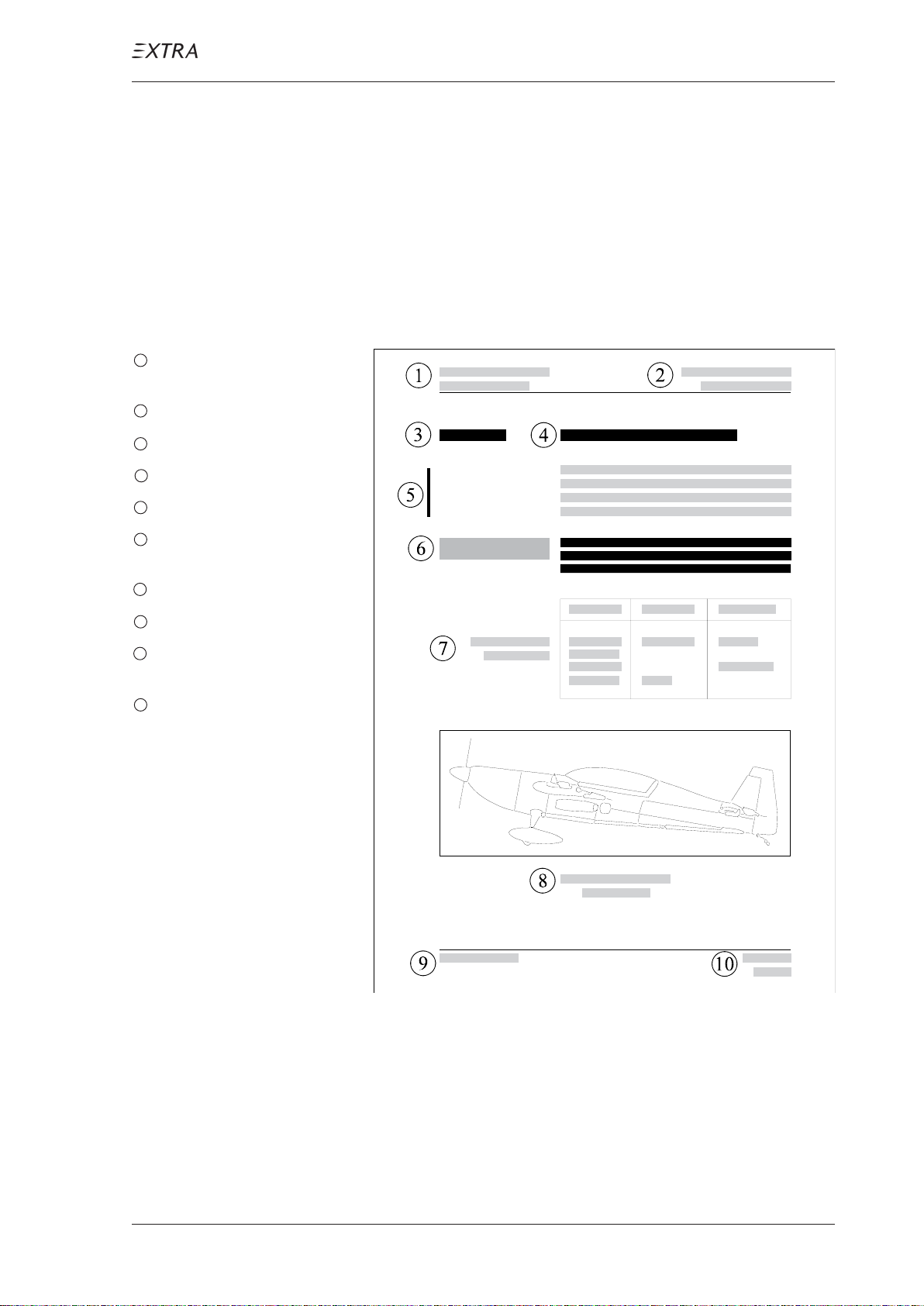
02-10-05 Layout
Apart from the headers and footers the layout consists of two
columns. The right column contains text, titles, tables,
schedules and figures (figures also can fill the whole page);
the left column contains the chapter numbering, boxed
textmarkers for notes and safety notes as well as explanations. The following figure1shows more details:
1 manufacturer´s masthead and
manual title
2 section and subject titles
3 chapter numbering
4 title
5 bar marking revised parts
6 boxed textmarker for notes and
safety notes
7 explanations e.g. to tables
8 figure title and number
9 date of first issue resp. last
revision
10 chapter and page numbers
Figure 1 Layout
P AGE DA TE: 7. July 2010 CHAPTER 2
PAGE 5
Page 22

MAINTENANCE MANUAL EXTRA 300L T
02-10-06 Notes/Safety Notes
Safety notes in this manual are marked by a boxed textmarker
in the margin column and written in semi-bold characters.
This manual distinguishes three warning levels:
D A N G E R Represents a threatening danger for the personnel. The
non-observation of this safety note will result in death
or serious injuries.
W A R N I N G Represents a possibly dangerous situation for the per-
sonnel. The non-observation of this safety note may result in injuries.
C A U T I O N Represents a danger to equipment. The non-observa-
tion of this safety note results in destruction of equipment. This safety note does not exclude a possible danger for the personnel.
Additional information given in this manual are also marked
by boxed textmarkers in the left column and are written in
semi-bold characters:
I M P O R T A N T Represents an important hint. Often used when the non-
observation of this safety note could endanger pilot or
passengers during aircraft operation.
N O T E Represents an useful or remarkable hint.
P AGE DA TE: 7. July 2010 CHAPTER 2
PAGE 6
Page 23

MAINTENANCE MANUAL EXTRA 300L T
02-20-00 HANDLING
02-20-01 Revisions
Maintenance manuals and other technical publications in
current revision status are available over the World Wide
Web direct link:
http://www.extraaircraft.com/techservice.php
Cross-check your documents against these publications and
replace pages as necessary. Paper copies of publications
will continue to be available if this is your preferred format
of publications. Orders can be placed by contacting Extra
Aircraft
at e-mail: [email protected]
or facsimile: +49-(0) 2858-9137-30.
N O T E Pages of this maintenance manual may not be exchanged
and no alterations of or additions to the approved
contents may be made without the EXTRA Flugzeugproduktuions- und Vertriebs GmbH/EASA approval.
If revision of pages is necessary, observe the following steps:
N O T E Change revised pages immediately upon receipt.
1 T ake out the old pages and destroy them.
2 Insert the new pages following the chapter and page numbers.
3 Replace the old pages "B-D = Log of Effective Pages".
4 Enter the date on page "A = Log of Revisions" and on page
"2 = Record of Revision" of Ch. 04 if necessary .
Each revised page is marked at the bottom by the date of
revision; revised parts of the new page are marked by a bar on
the left margin.
P AGE DA TE: 7. July 2010 CHAPTER 2
PAGE 7
Page 24
MAINTENANCE MANUAL EXTRA 300L T
02-20-02 Service Bulletin
The service bulletins describe which procedures and how
and when they are to be carried out. Enter the receipt of each
service bulletin in the Service Bulletin List (page E). Service
Bulletins are also available under the Web-link given in
section 02-20-01.
N O T E The owner is responsible for incorporating service
bulletins to the above mentioned Service Bulletins
List (page E).
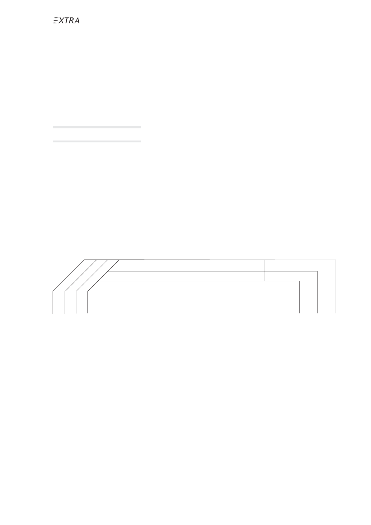
02-20-03 Checklists
each 50 hours
as specified
each 100 hours
O1O O T ext
Date:
Serial No.:
Observe the following steps when working with checklists:
1 Copy the respective check list for performing a check.
2 Enter the date at the top of the table.
Inspector:
Mechanic:
Inspections
3 Select the items to be worked out. The "O" at the beginning
of the line is written in the column which indicates the point
of time when an item has to be worked out. Specifications
for the first column are given by footnotes.
4 Work out the particular items and sign after execution (re-
sponsible mechanic and inspector) using the respective
boxes behind the item.
5 After completion of the inspection check file the list with
entries in the Aircraft Records.
6 Certify the completion of check in the Aircraft Log Book.
P AGE DA TE: 7. July 2010 CHAPTER 2
PAGE 8
Page 25

MAINTENANCE MANUAL EXTRA 300L T
02-20-04 Fax-Formats
When contacting EXTRA-Flugzeugproduktions- und
Vertriebs-GmbH is advisable in case of questions and/or
problems during maintenance of aircraft copy and use the
fax-format you find on the preceding pages ("H") for correct
identification of aircraft, equipment and existing technical
instructions. The data we request there are helpful for us to
provide you with the information you need.
P AGE DA TE: 7. July 2010 CHAPTER 2
PAGE 9
Page 26

MAINTENANCE MANUAL EXTRA 300L T
Chapter 3
General Description
P AGE DA TE: 7. July 2010
CHAPTER 3
PAGE 1
Page 27

MAINTENANCE MANUAL EXTRA 300L T
Table of Contents
Chapter/Figure Title
03-00-00 GENERAL . . . . . . . . . . . . . . . . . . . . . . . . . . . . . . . . . . 3
Figure 1 View EXTRA 300LT . . . . . . . . . . . . . . . . . . . . . . . . . . . . 3
03-10-00 DESCRIPTION . . . . . . . . . . . . . . . . . . . . . . . . . . . . . . 4
03-10-01 Construction . . . . . . . . . . . . . . . . . . . . . . . . . . . . . . . . . 4
03-10-02 Flight Control System . . . . . . . . . . . . . . . . . . . . . . . . . . 4
03-10-03 Brake System. . . . . . . . . . . . . . . . . . . . . . . . . . . . . . . . . 5
03-10-04 Powerplant . . . . . . . . . . . . . . . . . . . . . . . . . . . . . . . . . . 5
03-10-05 Fuel System . . . . . . . . . . . . . . . . . . . . . . . . . . . . . . . . . . 6
03-10-06 Electrical system. . . . . . . . . . . . . . . . . . . . . . . . . . . . . . 6
03-10-07 Instruments . . . . . . . . . . . . . . . . . . . . . . . . . . . . . . . . . . 7
P AGE DA TE: 7. July 2010
CHAPTER 3
PAGE 2
Page 28
MAINTENANCE MANUAL EXTRA 300L T
03-00-00 GENERAL
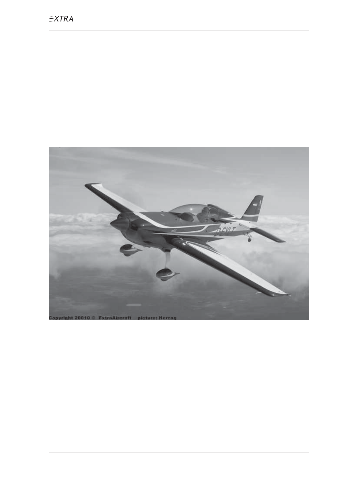
This chapter shows a short survey of the particular systems.
A more detailed description of the systems you find in the
respective chapters (see: CONTENTS).
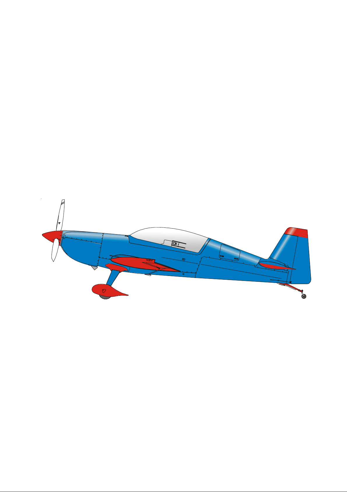
The Extra 300LT (refer to figure 1) is designed as a light
weight, single-engine, two seat, low-wing monoplane using
composite and steel materials. It has a fixed main landing
gear and a tail wheel unit with full-swivel capability .
Figure 1 View EXTRA 300LT
P AGE DA TE: 7. July 2010
CHAPTER 3
PAGE 3
Page 29

MAINTENANCE MANUAL EXTRA 300L T
03-10-00 DESCRIPTION
03-10-01 Construction
Manufacturer: EXTRA-Flugzeugproduktions- und
Fuselage: steel tube design, covered with
Wing: fibre composite design
V ertriebs- GmbH
Flugplatz Dinslaken
D-46569 Hünxe, Germany
fabric, composite material resp.
aluminium sheet metal,
single piece canopy side hinged
Stabilizers : fibre composite design
Landing gear: 2 main wheels, 1tail wheel, fibre
composite strut design
Seats
Rear Seat: Seat angle and seat back rest
adjustable, 5 piece harness
Front seat: non variable position, 5 piece
harness
03-10-02 Flight Control System
Pitch control: push-pull rods
Roll control: push-pull rods
P AGE DA TE: 7. July 2010
Y aw control: cable system
Pitch trim: trim tab on the right elevator,
bowden cable, electrical trim-servo,
trim switch, trim position indicator
CHAPTER 3
PAGE 4
Page 30

MAINTENANCE MANUAL EXTRA 300L T
03-10-03 Brake System
Main wheels: hydraulically operated disc brakes,
Tail wheel: no brake
03-10-04 Powerplant
Engine
Manufacturer: TEXTRON LYCOMING
hydraulic cylinders actuated by
brake pedals
Williamsport Division
652 Oliver Street
Williamsport Plant 17 701
USA
T ype: AEIO - 580-B1A
(6 cyl. air cooled, fuel injection,
independent magneto ignition
system, inverted flight oil system,
special antivibration counter
weights, retard breaker magneto,
Slick Start system)
Rated power: 315 hp at 2700 rpm
Propeller
Manufacturer: MT Propeller Entwicklung GmbH
& Co. KG
Airport Straubing
D-94348 Atting, Germany
T ype: MTV-9-B-C/C 198- 25
(3-blade wood composite,
hydraulic variable pitch with constant speed regulator,
Propeller diameter: 198 cm)
P AGE DA TE: 7. July 2010
CHAPTER 3
PAGE 5
Page 31

MAINTENANCE MANUAL EXTRA 300L T
03-10-05 Fuel System
T anks: 2 integral wing tanks, 1 center and
Fuel supply: mechanical engine driven pump,
03-10-06 Electrical system
Power supply: engine driven 12 V alternator,
1 acro tank behind the firewall
(cockpit side)
additional electrically operated
boost pump
integrated DV converter , alternator
switch, 28 Ah starter battery , battery
switch
Circuits: equipped with automatic circuit
breakers
Ignition: magneto system, independent from
electrical power supply
P AGE DA TE: 7. July 2010
CHAPTER 3
PAGE 6
Page 32
MAINTENANCE MANUAL EXTRA 300L T
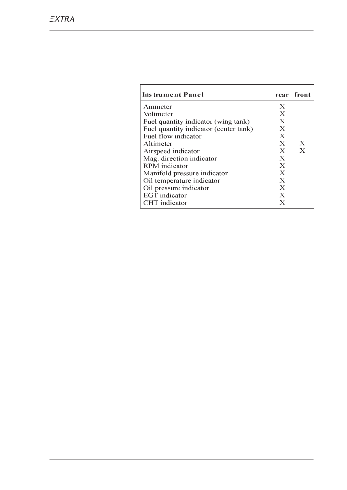
03-10-07 Instruments
Standard (minimum) equipment installed (X):
P AGE DA TE: 7. July 2010
CHAPTER 3
PAGE 7
Page 33

MAINTENANCE MANUAL EXTRA 300L T
Chapter 4
Airworthiness Limitations
P AGE DA TE: 30. April 2010
CHAPTER 4
PAGE 1
Page 34

MAINTENANCE MANUAL EXTRA 300L T
Log of Revisions Chapter 4
Dates of issue for original and revised pages:
1st Edition .............................................. 30. April 2010
Date and sign of approval:
EASA MAJOR CHANGE APPROV AL
N° 10030180.............................................. 1. June 2010
P AGE DA TE: 30. April 2010
CHAPTER 4
PAGE 2
Page 35

MAINTENANCE MANUAL EXTRA 300L T
Table of Contents
Chapter Title
04-00-00 GENERAL . . . . . . . . . . . . . . . . . . . . . . . . . . . . . . . . . . 4
04-00-01 Temperature Limit . . . . . . . . . . . . . . . . . . . . . . . . . . . . . 4
04-00-02 Operating Time . . . . . . . . . . . . . . . . . . . . . . . . . . . . . . . 4
04-10-00 LIFE LIMITED COMPONENTS . . . . . . . . . . . . . . . . 6
04-10-01 General . . . . . . . . . . . . . . . . . . . . . . . . . . . . . . . . . . . . . 6
04-10-02 Replacement Time. . . . . . . . . . . . . . . . . . . . . . . . . . . . . 6
04-10-03 Service Life Limited Components. . . . . . . . . . . . . . . . . 6
04-20-00 MAJOR INSPECTION . . . . . . . . . . . . . . . . . . . . . . . . 7
P AGE DA TE: 30. April 2010
CHAPTER 4
PAGE 3
Page 36

MAINTENANCE MANUAL EXTRA 300L T
04-00-00 GENERAL
For each inspection listed here, refer to the applicable
chapter in this manual.
I M P O R T A N T It is the operator's responsibility to make sure that time
limits or life limits for items in this chapter are not
exceeded.
The airworthiness limitations items include mandatory
replacement times and structural inspection intervals which
may only be changed with permission of the applicable
airworthiness authority.
This airworthiness limitation section is approved by the
regulatory authority and specifies maintenance required
under paragraphs 43.16 and 91.403 of the Federal A viation
Regulations, unless an alternative program has been ap-
proved by the regulatory authority .
04-00-01 Temperatur e Limit
Composite structure is qualified up to 72°C (162°F). Struc-
ture temperatures above this limit are not approved. Not to
exceed this temperature limit, only appropriate colour speci-
fication for composite structure as given by the manufac-
turer document EA-03205.19 must be used when finish
restoration is required.
In case of doubt regarding to the classification of colour,
contact EXTRA-Flugzeugproduktions- und V ertriebs-GmbH.
04-00-02 Operating Time
Only the airframe and components as listed in Chapter 04-
10-00 are subject to a permissible operating time; concern-
ing all other components recommended replacement times
are given in Chapter 05-10-03.
P AGE DA TE: 30. April 2010
CHAPTER 4
PAGE 4
Page 37

MAINTENANCE MANUAL EXTRA 300L T
Operating Time
The reliability of the composite primary parts has been
convincingly demonstrated by fatique testing (Two times
design life 2x6000 = 12000 hrs).
I M P O R T A N T Every 1000 flight hours the "Significant Items Inspec-
tion" contained in Chapter 05-30-00 of this manual must
be performed. This 1000 hours inspection releases the
aircraft for further 1000 hours operation, up to max. of
6000 hours.
I M P O R T A N T Prior to 6000 flight hours the "Major Inspection" con-
tained in Chapter 04-20-00 must be performed. This in-
spection may release the aircraft for further operation,
subject to approval of the regulatory authority.
GENERAL
P AGE DA TE: 30. April 2010
CHAPTER 4
PAGE 5
Page 38
MAINTENANCE MANUAL EXTRA 300L T
04-10-00 LIFE LIMITED COMPONENTS
04-10-01 General
The replacement time of the life limited components listed
in Ch. 04-10-02 must be accomplished not later than the
specified period of operation for that component or in
accordance with the manufacturer´s service data or airwor-
thiness directives.
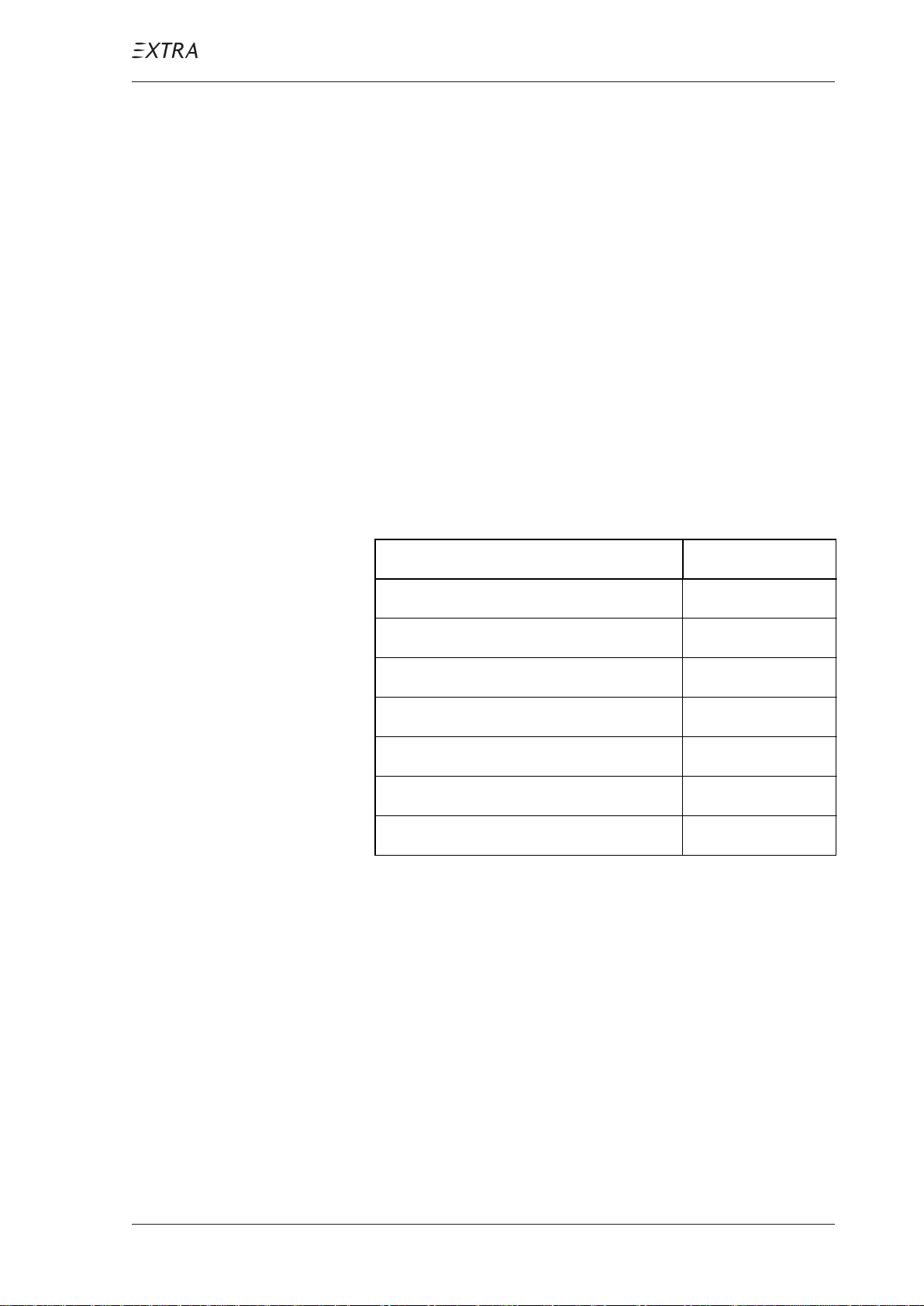
04-10-02 Replacement Time
Items shown here must be replaced during the regular
maintenance periods.
Item Replace
Wing 6000 h
Aileron 6000 h
Vertical Stabilizer 6000 h
Rudder 6000 h
Horizonal Stabilizer 6000 h
Elevator 6000 h
Landing Gear Spring 6000 h
04-10-03 Service Life Limited Components
The service life of the EA 300LT composite structure as
listed in section 04-10-02 has been set to 6000 flight hours.
A "Major Inspection" on reaching 6000 flight hours may
provide the necessary clearance for further flight. This
"Major Inspection" is contained in Chapter 04-20-00.
P AGE DA TE: 30. April 2010
CHAPTER 4
PAGE 6
Page 39

MAINTENANCE MANUAL EXTRA 300L T
04-20-00 MAJOR INSPECTION
The EXTRA 300LT has been manufactured utilizing the
latest knowledge of composite construction and requires
new experience about those parts subject to wear. Until now
insufficient experience about this point has been acquired.
When such information is available it will be accomodated
in later revisions of this manual and will include a major
inspection procedure.
P AGE DA TE: 30. April 2010
CHAPTER 4
PAGE 7
Page 40

MAINTENANCE MANUAL EXTRA 300L T
Chapter 5
Time Limits/Maintenance Checks
P AGE DA TE: 7. July 2010
CHAPTER 5
PAGE 1
Page 41

MAINTENANCE MANUAL EXTRA 300L T
Table of Contents
Chapter/Figure Title
05-00-00 GENERAL . . . . . . . . . . . . . . . . . . . . . . . . . . . . . . . . . . 3
05-10-00 TIME LIMIT COMPONENTS . . . . . . . . . . . . . . . . . . 4
05-10-01 General . . . . . . . . . . . . . . . . . . . . . . . . . . . . . . . . . . . . . 4
05-10-02 Overhaul Schedule . . . . . . . . . . . . . . . . . . . . . . . . . . . . . 4
05-10-03 Recommended Replacement Times . . . . . . . . . . . . . . . . 5
05-10-04 Time Between Inspection. . . . . . . . . . . . . . . . . . . . . . . . 6
05-20-00 SCHEDULED MAINTENANCE CHECKS . . . . . . . . 7
05-20-01 General . . . . . . . . . . . . . . . . . . . . . . . . . . . . . . . . . . . . . 7
05-20-02 25 Hour Inspection - Engine . . . . . . . . . . . . . . . . . . . . . 7
05-20-03 25 Hour Inspection - Aircraft . . . . . . . . . . . . . . . . . . . . 7
Figure 1 Drain and Vent Holes . . . . . . . . . . . . . . . . . . . . . . . . . . 8
Figure 2 Lubrication Chart 25 hours . . . . . . . . . . . . . . . . . . . . . 9
Figure 3 Lubrication Chart 50 hours . . . . . . . . . . . . . . . . . . . . 10
Figure 4 Lubrication Chart 100 hours . . . . . . . . . . . . . . . . . . . 11
05-20-04 Maintenance Checks Schedule . . . . . . . . . . . . . . . . . . 12
05-20-05 Significant Items Inspection . . . . . . . . . . . . . . . . . . . . 28
05-50-00 UNSCHEDULED MAINTENANCE CHECKS. . . . . 37
05-50-01 Violent Stopping of the Engine (Propeller Strike). . . . 37
05-50-02 Hard Landing . . . . . . . . . . . . . . . . . . . . . . . . . . . . . . . . 37
05-50-03 Engine Fire . . . . . . . . . . . . . . . . . . . . . . . . . . . . . . . . . 39
05-50-04 Lightning Strike . . . . . . . . . . . . . . . . . . . . . . . . . . . . . . 39
05-50-05 Flightline Inspections . . . . . . . . . . . . . . . . . . . . . . . . . 40
P AGE DA TE: 7. July 2010
CHAPTER 5
PAGE 2
Page 42

MAINTENANCE MANUAL EXTRA 300L T
05-00-00 GENERAL
This chapter contains charts for time limits, scheduled
maintenance and unscheduled maintenance, and enables li-
censed personnel to carry out correct inspections on the
EXTRA 300LT. The periodic inspections and checks de-
scribed and their recommended time intervals are minimum
requirements for maintaining the aircraft in an airworthy
condition. Further information will be given by the informa-
tion service (Service Bulletins, Service Letters, etc.).
If operation of aircraft requires more frequent servicing, the
check intervals may be shortened. However the check
intervals must not be exceeded without explicit permission
from the regulatory authority . Additional checks as well as
changes must also be authorised.
In general this manual does not give any information about
vendor equipment. Such information can be taken from the
vendor equipment maintenance instructions (refer to
chapter 1). However, for practicability reasons most of the
applicable vendor equipment inspections are incorporated
in the following checklists. But it has to be noted that the
latest editions of inspections given by the vendors remain
decisive. So, before beginning an inspection, the inspections
of vendor equipment presented here must be compared with
the originals referenced under the respective headlines of
the checklists, and, in case of doubt (e.g. if originals have
changed before changes could be transferred to this manual),
contact EXTRA-Flugzeug-produktions- und Vertriebs-
GmbH for advice. The maintenance instructions referenced
in the checklists are also valid if further inspection of vendor
equipment is necessary .
N O T E For working with checklists refer to chapter 02-20-
03.
D A N G E R Do not rotate the propeller nor allow any person to stay
P AGE DA TE: 7. July 2010
in the propeller operating area when performing an in-
spection or check. The engine may be started un-
intentionally and may cause serious injuries or death.
CHAPTER 5
PAGE 3
Page 43
MAINTENANCE MANUAL EXTRA 300L T
05-10-00 TIME LIMIT COMPONENTS
05-10-01 General
All components not listed herein should be inspected as
detailed in Chapter 05-20 „Maintenance Checks“ and re-
paired, overhauled as required. It is recommended that
overhaul or replacement of components should be accom-
plished not later than the specified period of operation for
that component or in accordance with the manufactures
service data or airworthiness directives.
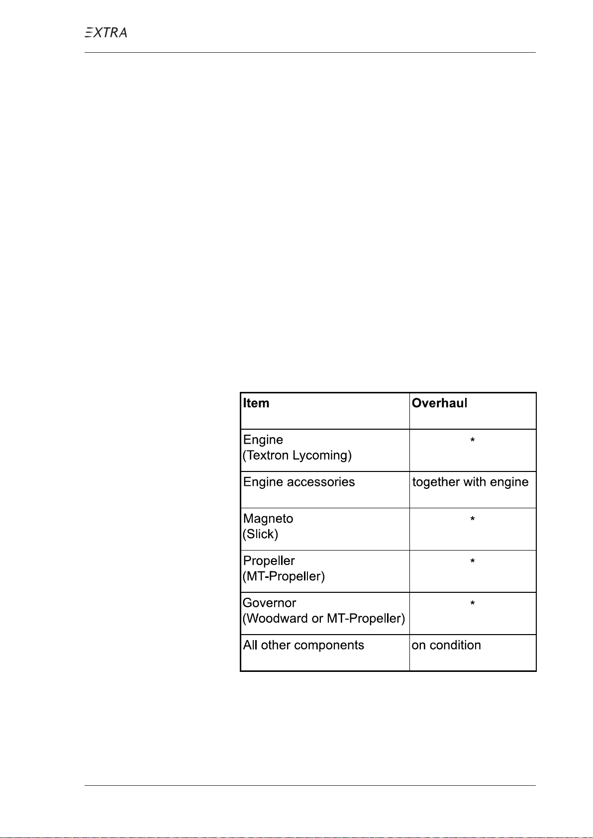
05-10-02 Overhaul Schedule
* refer to latest issue of
Manufacturer´s Service Bulletin
Items shown here must be overhauled at the times indicated.
P AGE DA TE: 7. July 2010
CHAPTER 5
PAGE 4
Page 44
TIME LIMIT COMPONENTS
MAINTENANCE MANUAL EXTRA 300L T
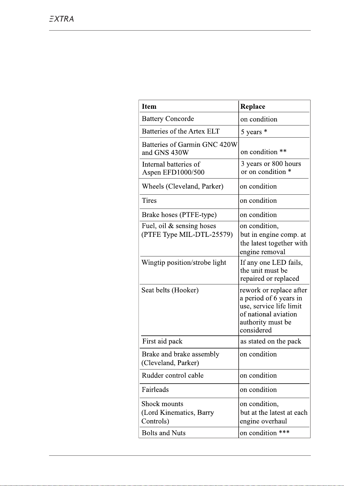
05-10-03 Recommended Replacement Times
It is recommended to replace the items shown in the following
schedule at the times indicated. The times may be modified
by the respective national authorities.
* on the recommendation
of the manufacturer
** recommended replacement
every 5 years to avoid
unscheduled maintenance
*** if not stated otherwise
P AGE DA TE: 7. July 2010
CHAPTER 5
PAGE 5
Page 45
MAINTENANCE MANUAL EXTRA 300L T
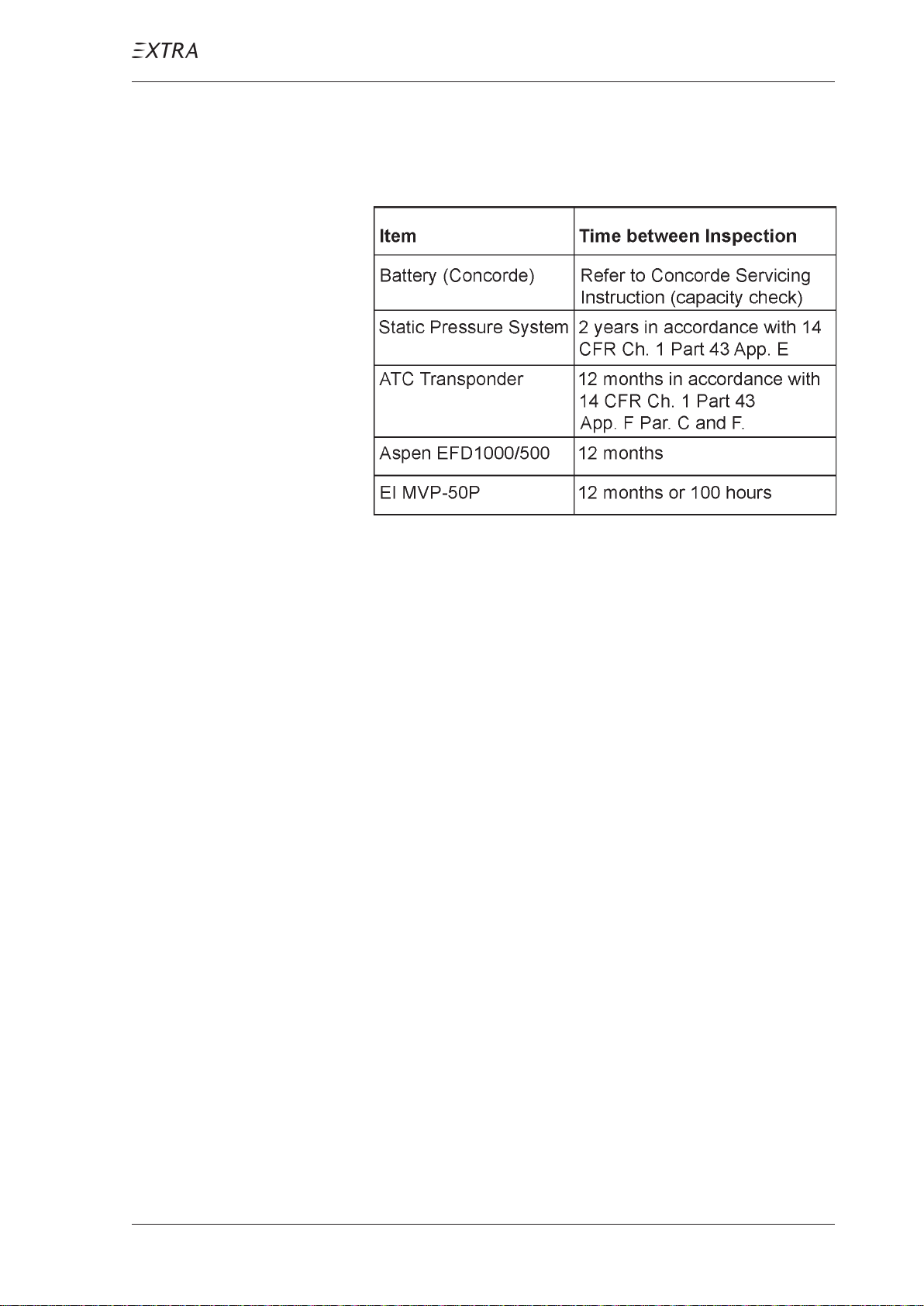
05-10-04 Time Between Inspection
Inspect these equipment items at the times shown:
P AGE DA TE: 7. July 2010
CHAPTER 5
PAGE 6
Page 46

MAINTENANCE MANUAL EXTRA 300L T
05-20-00 SCHEDULED MAINTENANCE CHECKS
05-20-01 General
Scheduled maintenance checks or tasks must be carried out
at 25, 50, 100, 200, 300, 400, 500 and 1000 hour intervals.
In addition an annual inspection equal to the 100 hour
inspection has to be performed.
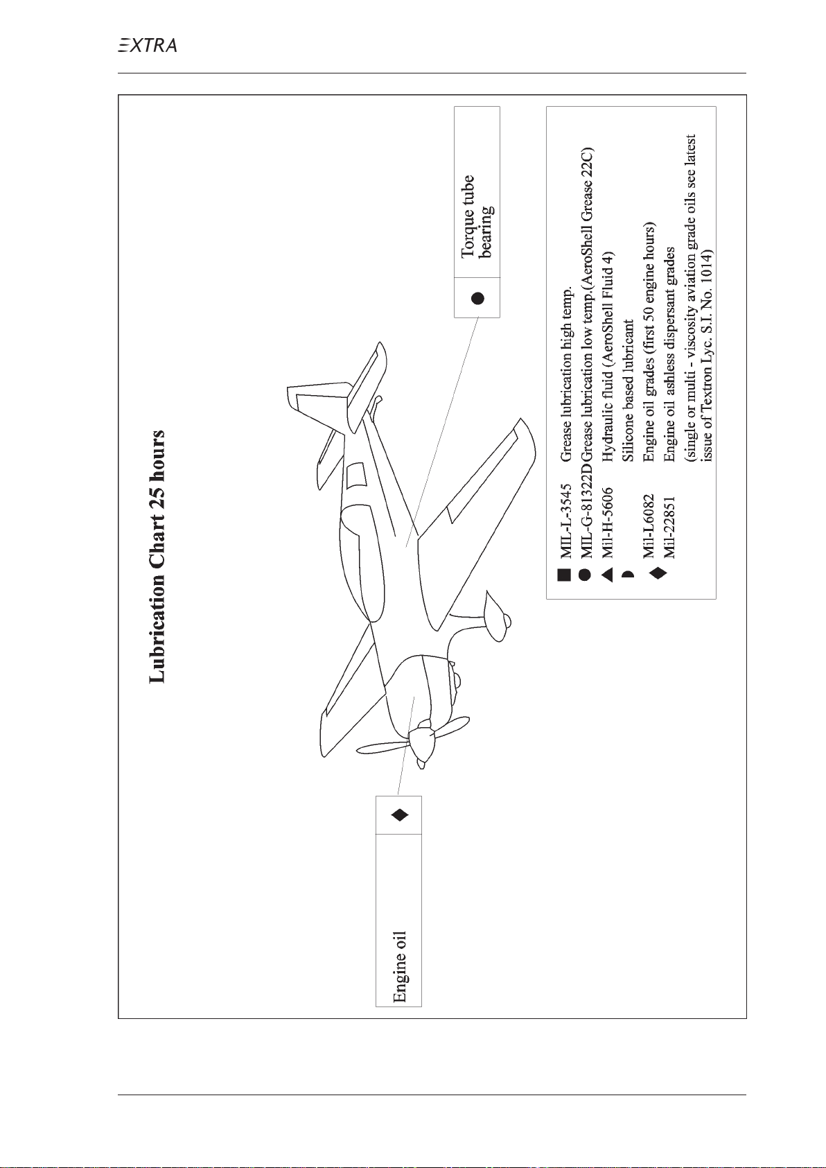
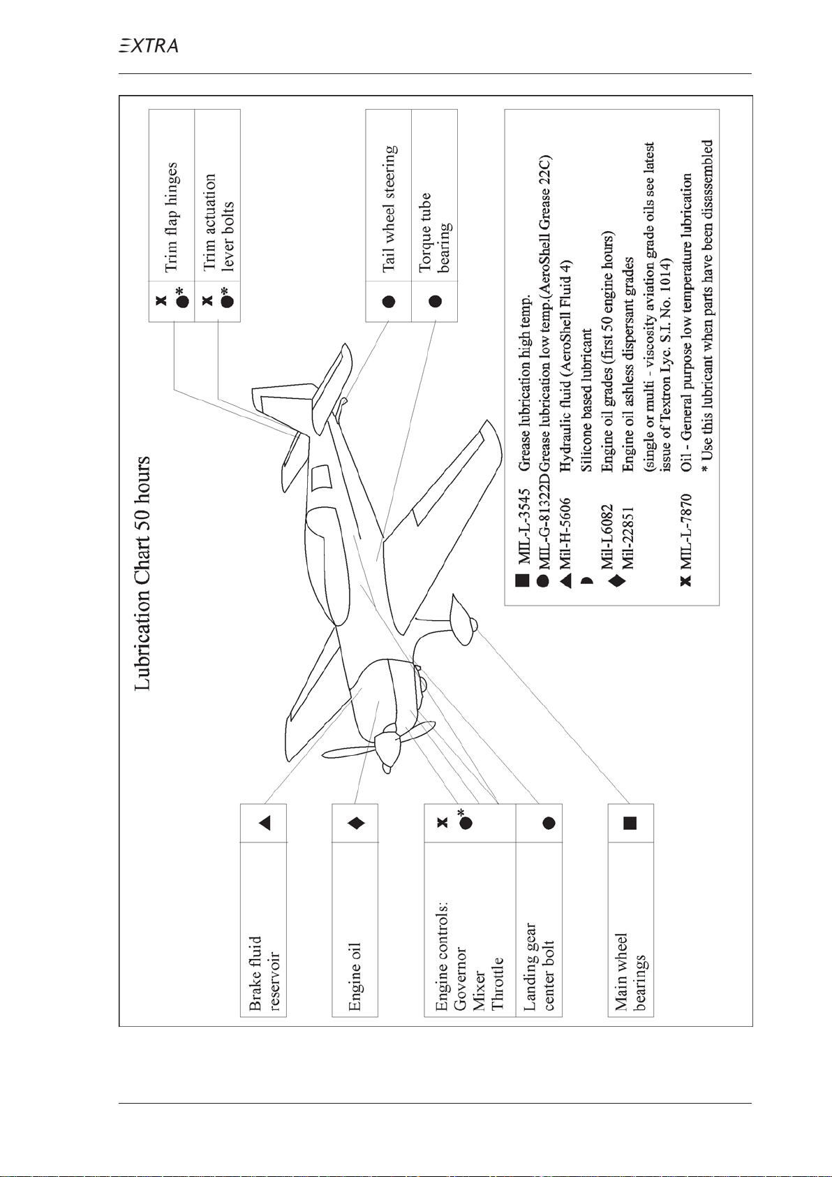
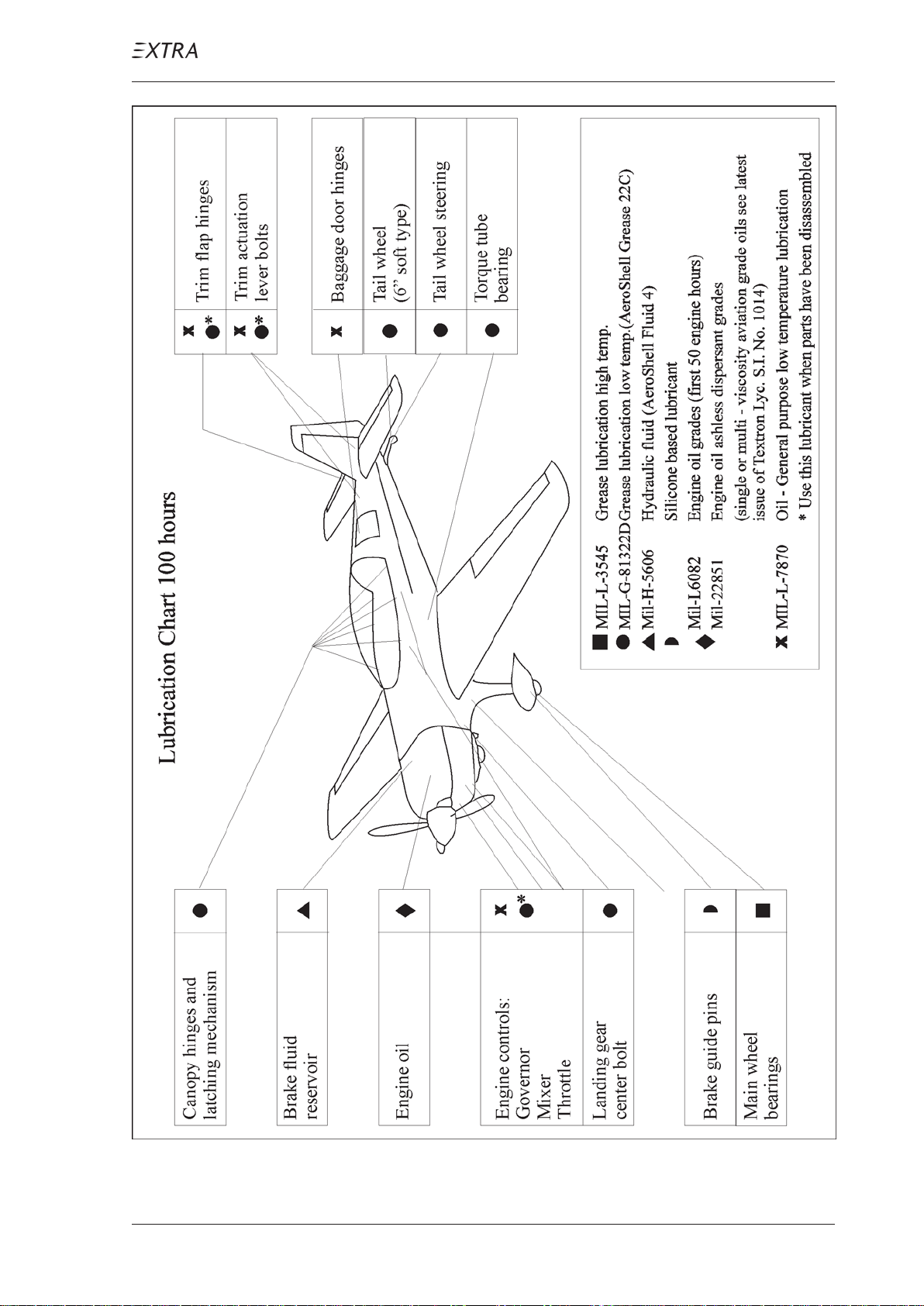
The following pages show a drain hole chart (figure 1) and
lubrication charts (figures 2 - 4) which can be used in
connection with the checklists.
05-20-02 25 Hour Inspection - Engine
A 25 hour inspection is necessary for the engine, because the
engine is not equipped with an external oil filter. Therefore
the engine oil has to be changed and the oil screen cleaned
after every 25 hours. Refer to figure 2 "Lubrication Chart 25
hours".
05-20-03 25 Hour Inspection - Aircraft
After the first 25 hours, a check equal to the 100-hour
maintenance check has to be performed. Refer to chapter
05-20-04.
P AGE DA TE: 7. July 2010
CHAPTER 5
PAGE 7
Page 47
MAINTENANCE MANUAL EXTRA 300L T
SCHEDULED MAINTENANCE CHECKS
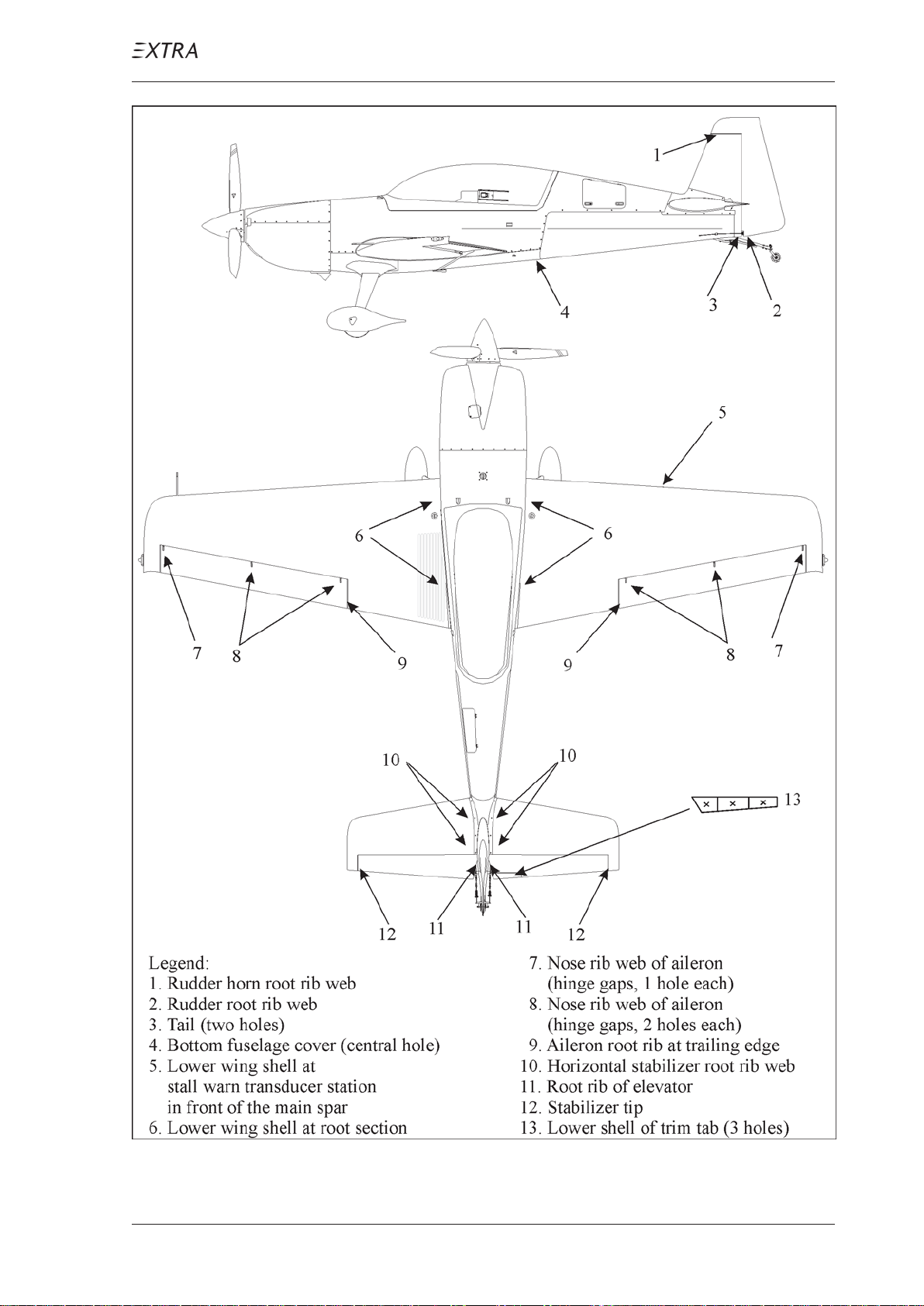
Figure 1 Drain and V ent Holes
P AGE DA TE: 7. July 2010
CHAPTER 5
PAGE 8
Page 48
MAINTENANCE MANUAL EXTRA 300L T
SCHEDULED MAINTENANCE CHECKS
Figure 2 Lubrication Chart 25 hours
P AGE DA TE: 7. July 2010
CHAPTER 5
PAGE 9
Page 49
MAINTENANCE MANUAL EXTRA 300L T
SCHEDULED MAINTENANCE CHECKS
Figure 3 Lubrication Chart 50 hours
P AGE DA TE: 7. July 2010
CHAPTER 5
PAGE 10
Page 50
MAINTENANCE MANUAL EXTRA 300L T
SCHEDULED MAINTENANCE CHECKS
Figure 4 Lubrication Chart 100 hours
P AGE DA TE: 7. July 2010
CHAPTER 5
PAGE 11
Page 51
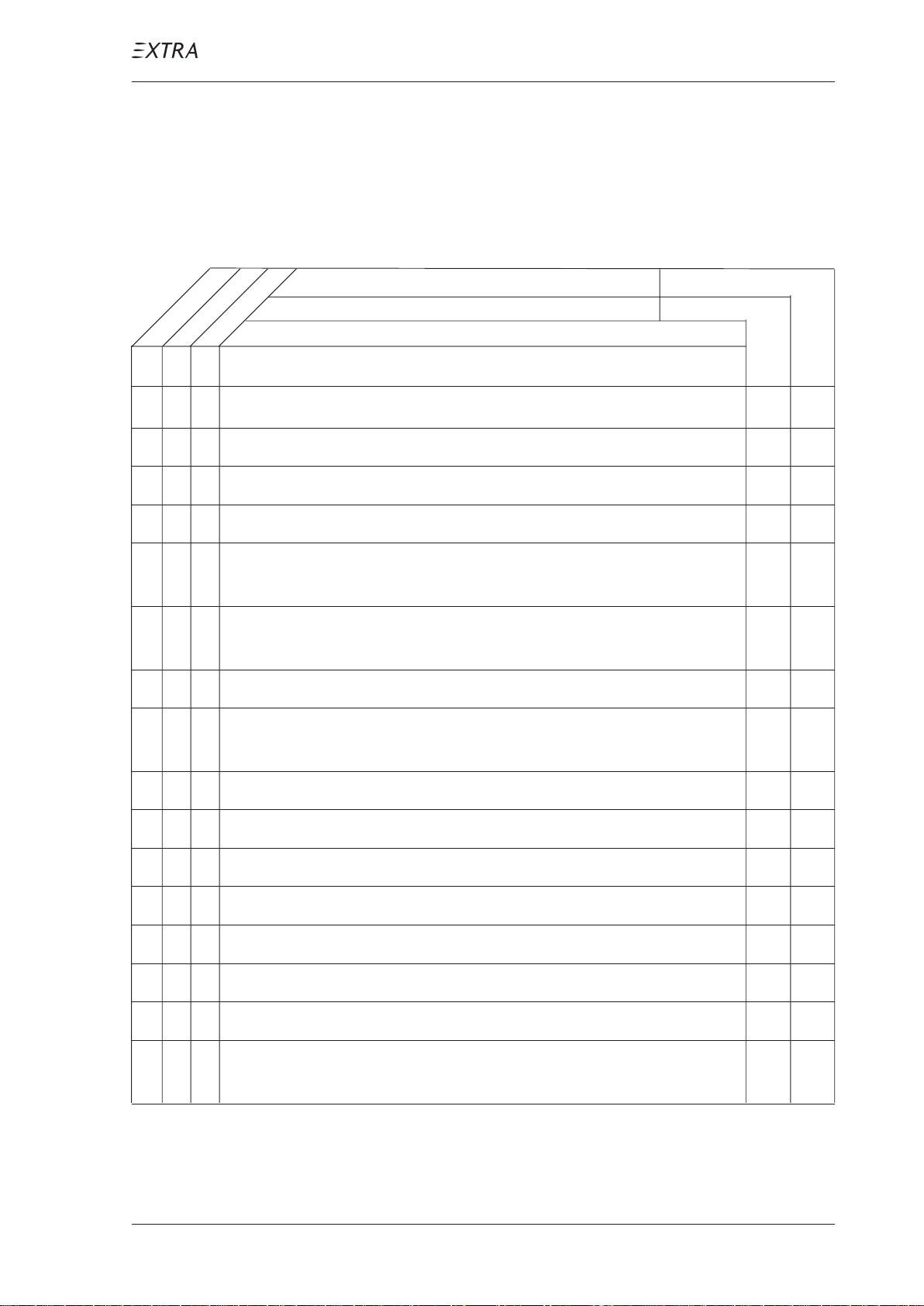
SCHEDULED MAINTENANCE CHECKS
MAINTENANCE MANUAL EXTRA 300L T
05-20-04 Maintenance Checks Schedule
The maintenance checks described in this chapter include all
the scheduled checks which must be performed. Use the
following schedule and the lubrication charts (figures 2-4).
as specified
each 50 hours
each 100 hours
Date:
Serial No.:
Inspections
Inspector:
Mechanic:
Operational Checks
O O 1 Start engine (in accordance with the Pilot`s Operating Handbook)
O O 2 Check the fuel quantity indication.
O O 3 Check oil pressure and temperature.
O O 4 Check generator output.
O O 5 Check magneto RPM-drop at 1800 RPM. (Allowed drop is
175 RPM and no greater diff. between L + R than 50 RPM)
O O 6 Check ignition OFF function at 1000 RPM for a short
moment.
O O 7 Check response of the engine by power setting changes.
O O 8 Check the propeller response at 1800 RPM when changing
pitch.
O O 9 Check idle rpm is between 650 and 750.
O O 10 Check the fuel flow and manifold pressure indicaton.
O O 11 Check the EGT and CHT indicaton.
O O 12 Check mixer function per CHT/EGT indication.
O O 13 Check idle mixture.
O O 14 Check the function of the fuel selector valve.
O O 15 Check the radio and the other electronic equipment.
O O 16 Shut down engine using mixture lever. Check the alternator
warning light and ammeter.
P AGE DA TE: 7. July 2010
CHAPTER 5
PAGE 12
Page 52
MAINTENANCE MANUAL EXTRA 300L T
SCHEDULED MAINTENANCE CHECKS
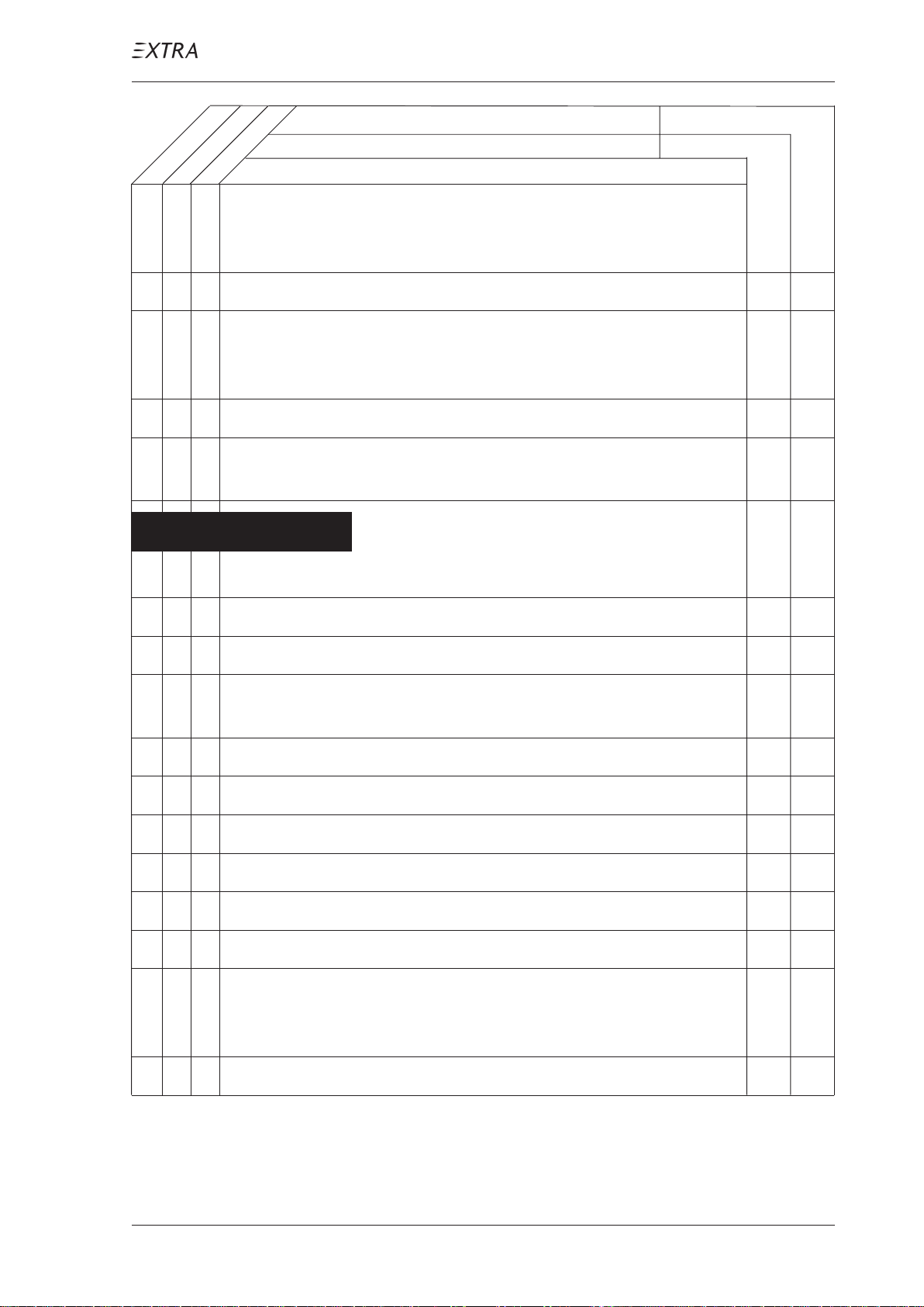
Maintenance Checks Schedule
each 50 hours
as specified
each 100 hours
Date:
Serial No.:
Inspections
Inspector:
Mechanic:
O O 17 Check optional electronic g-meter for the maximum g-
loading. If extreme value exceeds ±10 G , contact EXTRA-
Flugzeug-produktions- und V ertriebs- GmbH.
O O 18 Ignition OFF, main switch OFF , remove ignition key .
O O 19 Check if ignition key is removable in OFF-position only,
and if key functions in accordance with the requirements of
the T eledyne Continental Service Bulletin No. 636.
Propeller
(refer to latest edition of MT-Propeller Operation and
Installation Manual E-124 and Service Bulletins)
D A N G E R
Ground magneto primary circuit before
working on propeller
O 1 Remove spinner and inspect for cracks.
O O 2 Check blade shake, max. 3 mm or 1/8 inch.
O O 3 Check blade angle play, max. 2°.
O 4 Inspect outside condition of the hub and parts for cracks,
corrosion, deterioration.
O 5 Inspect high pitch stop check nut for tightness.
O O 6 Check all safety means to be intact.
O O 7 Check flange bolts or stop nuts for tightness.
O 8 Check front and rear spinner plate for cracks and fixing.
O O 9 Inspect blade root and hub for oil- and grease leaks.
O 10 Check position and condition of counterweights.
O O 11 Inspect blades for cracks in the fibreglass-cover and blade
erosion sheet. No cracks allowed. Refer to MT-Propeller
SB No. 8
1
O
1 refer to MT-Propeller Service Bulletin No. 1
P AGE DA TE: 7. July 2010
12 Overhaul propeller or perform a tear-down inspection.
CHAPTER 5
PAGE 13
Page 53
MAINTENANCE MANUAL EXTRA 300L T
SCHEDULED MAINTENANCE CHECKS
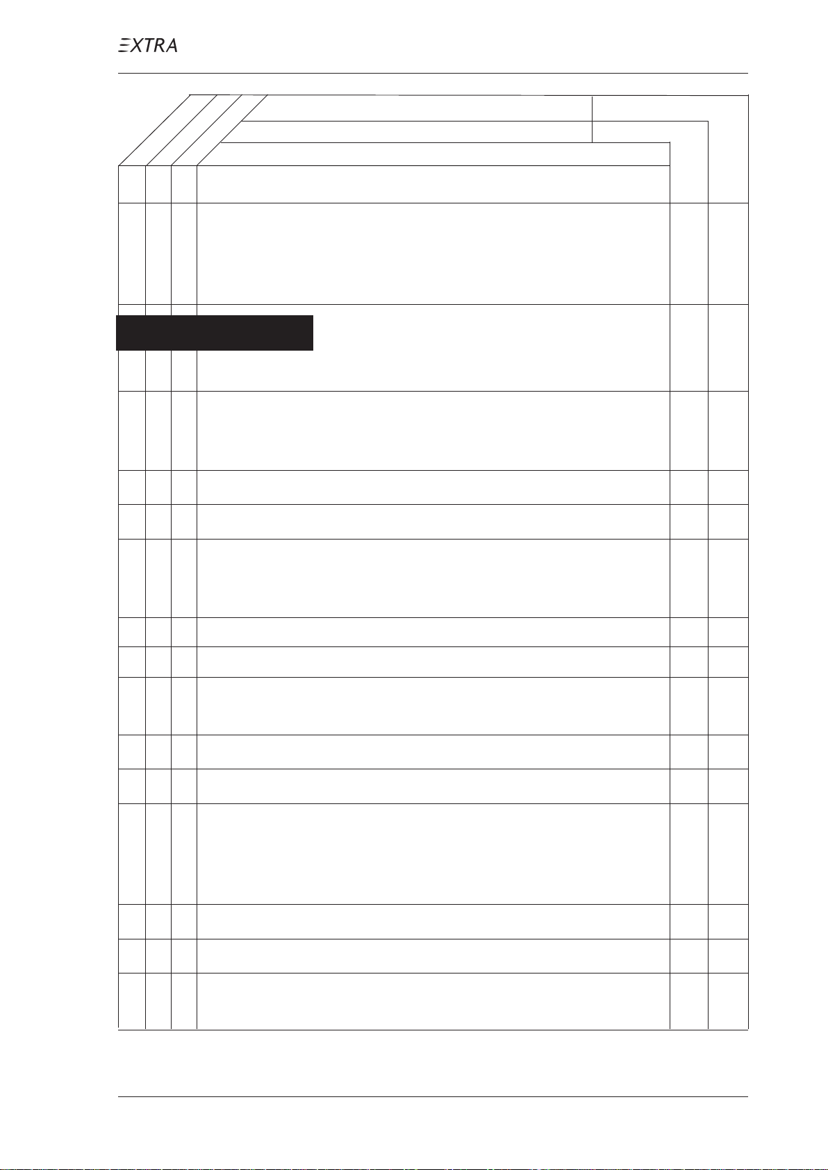
Maintenance Checks Schedule
as specified
each 100 hours
each 50 hours
Date:
Serial No.:
Inspections
Inspector:
Mechanic:
Engine compartment
(Refer to latest edition of T extron L ycoming Operator´s and
Maintenance Manual and SB's, Christen Product Manual
801 Series and SB's, Slick Magneto Maintenance and Overhaul Manual and SB's.
D A N G E R
O O 1 Remove engine cowling as per chapter 71.
O O 2 Inspect cowling and air inlet screen for damage, cracks,
distortion, overheated areas and loose or missing blind nuts
and secure attachment of oil level access plate.
O O 3 Inspect landing light for dirt.
Ground magneto primary circuit before
working on engine
O O 4 After this inspection clean cowling.
O O 5 Check fire engine cowling protection. If necessary repaint
the fire protective paint N 56582 / T508 and lacquer 4232-
0303.
O1O O 6 Drain oil sump in accordance with chapter 12-10-04.
O1O O 7 Clean and inspect oil screen filter.
1
O O 8 Clean suction oil strainer at oil change (check strainer for
O
foreign particles).
O1O O 9 Clean pressure oil strainer (check for foreign particles).
O 10 Inspect oil temperature sensor unit for leaks and security.
O O 11 Inspect flexible oil lines, oil return lines and fittings for
leaks, security , chafing, dents, and cracks (ref: FAA AC
43.13-1A). Replace flexible oil lines at engine TBO per
L yc. SB 240.
O 12 Clean and inspect oil radiator and attachment.
2
O
13 Remove and flush oil radiator.
O O 14 Inspect Christen Inverted Oil System for general condition,
leaks, secure mounting and tight connections.
1 at first 10 hours, and each 25 hours thereafter
2 each 500 hours
P AGE DA TE: 7. July 2010
CHAPTER 5
PAGE 14
Page 54
MAINTENANCE MANUAL EXTRA 300L T
SCHEDULED MAINTENANCE CHECKS
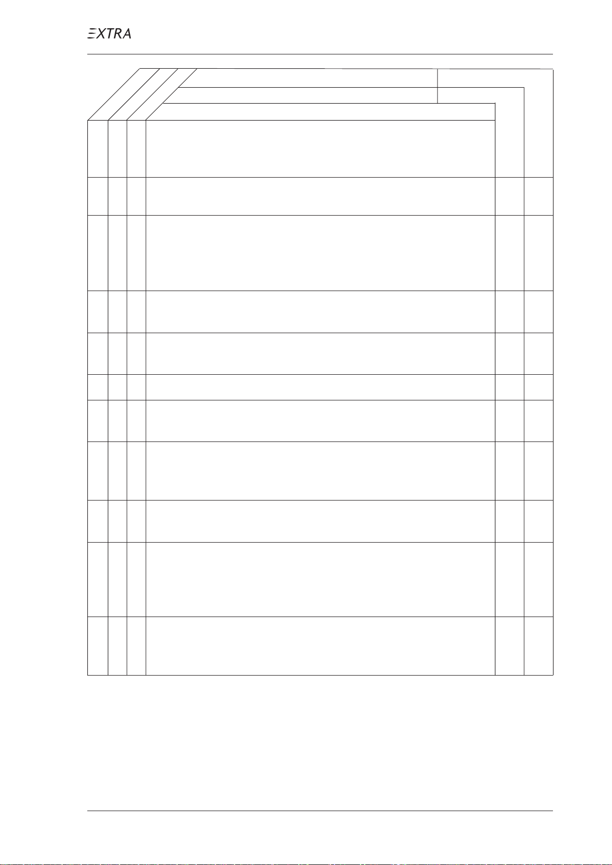
Maintenance Checks Schedule
as specified
1
O
Date:
Serial No.:
each 50 hours
each 100 hours
Inspections
15 Clean and flush the Inverted Oil System with a suitable
Inspector:
Mechanic:
petroleum solvent, such as Varsol according to L ycoming
Operator’s and Maintenance Manual.
2
O O 16 Service engine with recommended lubricating oil in accord-
O
ance with chapter 12-10-04.
O O 17 Inspect condition of spark plugs (clean and adjust gap as
required, adjust per Lycoming Service Instruction 1042). If
fouling of spark plugs is apparent, rotate bottom plugs to
upper plugs and vice versa.
O O 18 Inspect spark plug cable leads and ceramics for corrosion
and deposits.
O O 19 Perform a hot engine differential compression check in
accordance with FAA AC 43.13-1A.
O 20 Inspect cylinders for cracked or broken fins.
O O 21 Check cylinders for evidence of excessive heat which is
indicated by discoloration.
O 22 Check fuel injector nozzles for loseness. Tighten to 60
inch-pounds torque. Check fuel lines for fuel stains which
are indicative for fuel leaks.
O O 23 Inspect rocker box covers for evidence of oil leaks. If
found, replace gasket; torque cover screws 50 inch-pounds.
O
3
24 Remove rocker box covers and check for freedom of valve
rockers when valves are closed. Look for evidence of abnormal wear or broken parts in the area of valve tips, valve
keeper, springs and spring seats.
O 25 Inspect ignition harness for general condition, free from
fraying or chafing and insulators for high tension leakage
and continuity.
1 each 300 hours
2 each 25 hours
3 each 400 hours
P AGE DA TE: 7. July 2010
CHAPTER 5
PAGE 15
Page 55
MAINTENANCE MANUAL EXTRA 300L T
SCHEDULED MAINTENANCE CHECKS
Maintenance Checks Schedule
as specified
1
O
2
O
3
O
2
O
2
O
each 50 hours
each 100 hours
Date:
Serial No.:
Inspections
Inspector:
Mechanic:
26 Overhaul or replace magnetos.
O 27 Adjust magneto to engine timing, refer to Slick Magneto
Maintenance and Overhaul Manual
O 28 Inspect magneto wiring connections, vent holes and P-lead
attachment, refer to Slick Magneto Maintenance and Over-
haul Manual.
29 Clean magnetos.
30 Replace magneto ball bearings.
31 Inspect magneto ball bearing assembly , impulse coupling,
coil, contact points, condenser and carbon brush.
32 Lubricate magnetos.
O 33 Inspect SlickST ART , refer to Unison Operation,
Maintenance and Troubleshooting Manual.
O 34 Check fuel injector for general condition, clean fuel inlet
screen.
O O 35 Inspect air intake seals and O-rings for leaks and clamps for
tightness.
O O 36 Inspect flexible fuel lines, fuel injection lines and fittings
for leaks, security , chafing, dents, and cracks (refer to
L ycoming SB 342 each 100 h; replace or overhaul as re-
quired or at engine overhaul).
O O 37 Check fuel system for leaks.
4
O O 38 Remove, clean and inspect gascolator screen and fuel filter
O
bowl.
O O 39 Inspect throttle, mixture, and propeller governor controls
for security , travel, and operating conditions. Observe the
hints given in the Inspections-paragraph of chapter 20-10-
09 Control Cables.
1 together with engine
2 each 500 hours
3 each 1000 hours
4 clean at least every 90 days
P AGE DA TE: 7. July 2010
CHAPTER 5
PAGE 16
Page 56
MAINTENANCE MANUAL EXTRA 300L T
SCHEDULED MAINTENANCE CHECKS
Maintenance Checks Schedule
as specified
1
O
1
O
1
O
1
O
1
O
1
O
each 50 hours
each 100 hours
Date:
Serial No.:
Inspections
Inspector:
Mechanic:
O 40 Inspect all external exhaust surfaces for signs of leakage.
O 41 Inspect all external exhaust joints, slip joints, clamps,
couplings for misalignment, warpage, broken, loose or
missing fasteners, clamps, gaskets or seals and abnormal
wear.
O 42 Inspect all interior exhaust areas for blockage, restrictions,
dents or protrusions into the exhaust flow path.
O 43 Inspect muffler, heat exchanger for general condition.
O 44 Inspect exhaust stack to flange interface for cracks in welds
or weld heat affected area, blown out or missing gaskets.
O 45 Inspect all exhaust welds and area adjacent to the weld for
cracks or weld separation.
1
O
O 46 Inspect bent exhaust areas and turns for erosion, thinning,
bulging or burn through.
1
O
O 47 Inspect surrounding exhaust structures for heat damage or
burning.
O 48 Inspect engine crankcase for cracks, leaks, and security of
seam bolts.
O O 49 Check engine mounted accessories such as pumps, tem-
perature and pressure sensing units for leaks, secure
mounting and tight connections.
O O 50 Inspect engine mount for cracks and loose mountings.
O O 51 Inspect engine baffles for cracks and fraying.
O 52 Inspect all wiring connected to the engine or accessories
O O 53 Inspect engine shock mount for deterioration (replace as
required).
O 54 Inspect firewall seals.
O 55 Inspect alternator, cable connections and accessories.
1 at engine replacement
P AGE DA TE: 7. July 2010
CHAPTER 5
PAGE 17
Page 57
MAINTENANCE MANUAL EXTRA 300L T
SCHEDULED MAINTENANCE CHECKS
Maintenance Checks Schedule
as specified
each 50 hours
each 100 hours
Date:
Serial No.:
Inspections
Inspector:
Mechanic:
O 56 Inspect condition and tension of alternator drive belt
O 57 Inspect security of alternator mounting
O 58 Inspect starter and starter drive
O O 59 Clean engine if necessary.
O O 60 Lubricate all controls per lubrication chart.
1
O
O
2
61 Overhaul or replace propeller governor as required.
62 Complete overhaul of engine or replace with factory rebuilt
Fuselage
O O 1 Remove tail fairing, tail side skins, main fuselage cover and
landing gear cuffs per chapters 51 and 53.
O 2 Remove bottom fuselage cover including exhaust area
covering sheet per chapter 53.
O O 3 Inspect main and bottom fuselage cover including exhaust
area covering sheet, tail fairing, tail side skins and landing
gear cuffs for general condition, dents, cracks and loose
screws.
O O 4 Inspect baggage compartment structure for cracks and
damage.
O O 5 Inspect baggage net and tie-down straps for security ,
attachment, proper operation and condition.
O O 6 Check installed parts for general condition and security of
attachment.
O O 7 Inspect fuselage for foreign objects.
O 8 Inspect steel tube construction for general condition, cor-
rosion and cracks, above all in areas of load stress (e.g.
wing, stabilizer, engine and seat attachments).
1 refer to Woodward Service Bulletin No. 33580 or
applicable MT-Propeller Instructions
2 refer to Lycoming Service Instruction No. 1009
P AGE DA TE: 7. July 2010
CHAPTER 5
PAGE 18
Page 58
MAINTENANCE MANUAL EXTRA 300L T
SCHEDULED MAINTENANCE CHECKS
Maintenance Checks Schedule
as specified
each 50 hours
each 100 hours
Date:
Serial No.:
Inspections
Inspector:
Mechanic:
O O 9 Visually inspect steel tube construction in the area of hori-
zontal stabilizer attach brackets for cracks. In case of doubt
remove horizontal stabilizer and use a dye check penetrant.
In case cracks are found contact EXTRAFlugzeugproduktions- und V ertriebs- GmbH for repair
advice.
O O 10 Inspect fabric cover for general condition.
O 11 Inspect wooden longerons for damage.
O 12 Clean and lubricate canopy hinges and latching mechanism.
O 13 Inspect breather line for obstructions and security.
O 14 Inspect main and auxiliary wing spar connector for general
condition.
O O 15 Inspect seats for security, attachment, proper operation, and
condition.
O O 16 Check first-aid pack for attachment, complete contents and
expiration date.
Seat belts
O 17 Check seat belts for security, attachment, proper operation,
and condition.
O 18 Check webbing; inspect for fuzzy edges at the adjusters,
inspect whether edges start to fray , inspect whether webbing
lost its color (top and bottom sides have a different shades).
O 19 Check hardware; inspect for corrosion, check whether
buckles mate properly . Check the buckles for easy opening .
O 20 Check ratchet assembly; inspect for corrosion, loss of
plating, discoloration, slippage and wear; check for ease of
operation.
If the harness does not pass the check, it has to be reworked
or replaced. Contact the harness manufacturer in case of
doubt.
21 Check proper attachment of shoulder harness as per chapter
25-10-03.
P AGE DA TE: 7. July 2010
CHAPTER 5
PAGE 19
Page 59
MAINTENANCE MANUAL EXTRA 300L T
SCHEDULED MAINTENANCE CHECKS
Maintenance Checks Schedule
as specified
each 50 hours
each 100 hours
Date:
Serial No.:
Inspections
Inspector:
Mechanic:
Fuel system
O O 22 Inspect the fuel lines for leaks, security, chafing, dents and
cracks. Replace fuel lines as required.
O O 23 Inspect fuel selector valve for operation and proper pointer
indication. Check integrity as per chapter 28-20-01.
O O 24 Drain fuel system.
O O 25 Check acro- and center tank attachments.
O O 26 Check acro-, center- and both wingtanks for leaks.
O O 27 Check boost pump.
O O 28 Check fuel filler caps and 'O'-rings for security and proper
operation.
O O 29 Check proper seat and condition of fuel filler sealing lip.
Flight controls
O O 1 Remove wing access panels.
O O 2 Inspect control surfaces for security of attachment, free
movement, dents, delaminations and cracks.
O O 3 Check spades visually for general condition. Inspect spade
support for corrosion, cracks and deformations. Ensure
proper attachment to aileron.
O O 4 Inspect elevator trim system for proper operation and
rigging.
O O 5 Inspect hinges, hinge bolts, hinge bearings and selflocking
nuts for condition, cracks and security .
O O 6 Visual inspect bonding braid across the hinges for general
condition.
O O 7 Check free play in control system: torque tube, control
surfaces, control sticks, rod end bearings and travel stops.
O1O O 8 Lubricate rear torque tube bearing.
O O 9 Lubricate trim flap hinges and trim actuation lever bolts.
1 each 25 hours
P AGE DA TE: 7. July 2010
CHAPTER 5
PAGE 20
Page 60
MAINTENANCE MANUAL EXTRA 300L T
SCHEDULED MAINTENANCE CHECKS
Maintenance Checks Schedule
Date:
Serial No.:
as specified
each 50 hours
each 100 hours
Inspections
O 10 Check rudder cable system including sleeves, fairleads,
pulleys and cable retracting springs per F AA-AC 43.13-1A.
O O 11 Check PTFE tube within the S-guidance at the rear seat
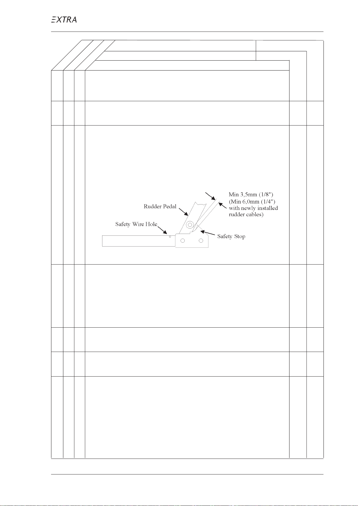
rudder pedal for general condition.
O 12 Check for minimum 3.5 mm (1/8") clearance of rudder
pedal versus safety stop when fully deflected for rudder
cables having 50 h flight time minimum. On newly installed
rudder cables the minimum spacing is 6 mm (1/4"). This
check is to be performed with zero loading on the rudder
pedals.
Inspector:
Mechanic:
O 13 Rough check of safety stop clearance. With a force of
approx. 90 kg (200 lbs) acting on the fully deflected rudder
pedal the safety stop shall not be reached. If the stop is
reached the control system indicates too much flexibility
which needs to be traced. In this case contact EXTRA
Flugzeugproduktions- und V ertriebs- GmbH for advice.
O O 14 Inspect all flight control surface ventilation holes for
obstruction.
O 15 Inspect elevator balance weights for looseness, clearance,
condition and interference with the composite structure.
O 16 Visual inspect push/pull control rods for corrosion, cracks,
or other visible damage, especially at their end fittings. In
case of suspected cracks, remove push/pull control rod,
strip the paint in the suspected area and carry out a detailed
inspection using a magnifying glass (x10). Replace the
related control rod in case a crack is found otherwise
reapply surface treatment and reinstall push/pull control
rod.
P AGE DA TE: 7. July 2010
CHAPTER 5
PAGE 21
Page 61
MAINTENANCE MANUAL EXTRA 300L T
SCHEDULED MAINTENANCE CHECKS
Maintenance Checks Schedule
as specified
each 50 hours
each 100 hours
Date:
Serial No.:
Inspections
Inspector:
Mechanic:
Landing gear
O O 1 Check landing gear for general condition.
O O 2 Visually inspect main landing gear spring for dents and
cracks.
O 3 Visually inspect main landing gear spring for deformations,
especially in the area of the mounting clamps. Inspect the
axle attachments, when wheels and brake callipers are
removed (refer to paragraph "Wheels" below).
O O 4 Inspect landing gear spring mounting clamps and bolts for
security.
O 5 Lubricate landing gear center bolt and landing gear
mounting clamps hinge bolts.
O 6 Check wheel rake (10° ± 1°) and toe-in (2.5° ± 0.5°)
(landing gear not loaded) as per chapter 32.
Fairings
O O 7 Remove and disassemble wheel fairings.
O O 8 Check wheel fairings, inspection caps and heat protection
sheet for dents and cracks.
Wheels
9 (Refer to on-aircraft inspections presented in the latest
edition of Cleveland Wheels & Brakes Maintenance Manual
and Service Bulletins for wheel, tire and brake inspections)
O O 10 Visually inspect the wheels for slippage, corrosion, cracks
or other visible damage.
O O 11 Check the four bolts attaching the wheel axis to the landing
gear spring. Inspect nuts for signs of starting to be pulled
off the bolts. Nuts have to be on the inboard side of the
landing gear spring.
O O 12 Check wheel nuts to be sure they are properly installed.
Bolt threads should be flush to 1-1/2 threads extending
beyond the nut. Nuts have to be on the side of wheel
opposite the brake disc (outboard side of wheel).
P AGE DA TE: 7. July 2010
CHAPTER 5
PAGE 22
Page 62
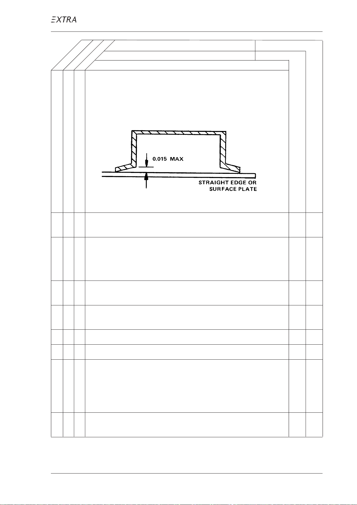
MAINTENANCE MANUAL EXTRA 300L T
SCHEDULED MAINTENANCE CHECKS
Maintenance Checks Schedule
as specified
each 50 hours
each 100 hours
Date:
Serial No.:
Inspections
Inspector:
Mechanic:
O O 13 Inspect the brake disc for rust, excessive grooves, large
cracks, coning or other visible damage. Check if disc thick-
ness is more than 0.325in/8.255mm. Coning of disc in
excess of 0.015 in /0.381 mm is cause for replacement.
O 14 Remove wheels and wheel bearings. Inspect wheel bearing
grease for contamination and solidification.
O 15 Inspect snap rings and grease seals for distortion or wear.
Replace grease seal felts if they are hard or contaminated.
Lightly saturated grease seals should be replaced if cracked,
dried out, or distorted.
O 16 Inspect wheel bearings for excessive wear or damage.
Replace on condition.
O 17 Repack bearings with AEROSHELL 17C (per MIL-L-3545),
or equivalent. Reinstall wheels and secure.
O O 18 Check wheel bearing clearance and wheels for free rotation.
Tires
O O 19 Visually inspect tires for cuts, flat spots, and tread or
sidewall damage. If changing of tires is necessary , follow
the instructions, including off-aircraft inspection of wheels,
presented in the Cleveland Wheels & Brakes Component
Maintenance Manual.
O O 20 Check inflation pressure (3.4 bar/49 psi). Proper inflation
will provide maximum tire and wheel life.
P AGE DA TE: 7. July 2010
CHAPTER 5
PAGE 23
Page 63
MAINTENANCE MANUAL EXTRA 300L T
each 50 hours
as specified
each 100 hours
Date:
Serial No.:
Inspections
Inspector:
Mechanic:
Brake system
O O 21 Inspect brake assemblies for general condition.
O O 22 Inspect master cylinders for leaks.
O 23 Inspect brake lines for leaks, bulges and deterioration.
Inspect brake lines for kinks, especially in the extreme
positions of pedals. Inspect brake lines for chafing,
especially in lead-through areas.
O 24 Lubricate brake guide pins using Silicone-base lubricant.
O O 25 Visually inspect the brakes for corrosion, cracks, or other
visible damage. Inspect inlet fitting bosses and anchor bolt
lugs for cracks.
O O 26 Check back plate attachment bolts to insure they are
properly torqued and have not worked loose. Gaps between
the back plate and cylinder would be evidence of this.
O O 27 Check fit of brake cylinder anchor bolts in torque plate
bushings for sloppiness. This can be accomplished by grasp-
ing the cylinder and moving it; slight movement is normal.
Excessive movement is cause for removal and detailed
inspection.
O O 28 Visually inspect brake linings for extreme chipping on the
edges. Lining worn to a minimum thickness of 0.100 inch
(2.54 mm) must be replaced.
O O 29 Visually check torque plate for corrosion, cracks, loose
anchor bolt bushings, or other visible damage. Anchor bolt
bushings must be flat against torque plate surface.
O O 30 Check for any brake fluid leaks.
O O 31 Check brake fluid level (fill as required).
Steerable tail wheel landing gear
O O 32 Check tail wheel landing gear for general condition and
function. Pay attention to the free movement of the rudder .
O O 33 Check tail wheel landing gear spring for dents, cracks, and
delaminations.
P AGE DA TE: 7. July 2010
CHAPTER 5
PAGE 24
Page 64
MAINTENANCE MANUAL EXTRA 300L T
as specified
each 100 hours
each 50 hours
Date:
Serial No.:
Inspections
Inspector:
Mechanic:
O O 34 Check tail wheel rubber tire condition.
O O 35 Inspect tail wheel fork and swivel arm mounting bolt for
security.
O O 36 Check the connector springs for light precompression.
O O 37 Check the wheel fork for free rotation and steering
function, damage, dents, cracks and corrosion.
O O 38 Inspect axle bolt and nut for fretting, wear, damage and
stretch.
O O 39 Lubricate tail wheel steering.
Wing
O O 1 Check wing for dents, cracks, and delaminations.
O 2 Inspect wing spar main bolts for looseness and security.
O 3 Check the safety wire and the safety screw of the wing main
spar bolt.
O 4 Inspect wing spar main sleeves for looseness and bearing
load.
O 5 Inspect wing auxiliary spar attachment.
O 6 Inspect wing ventilation holes for obstruction.
O O 7 Check inside wing structure in the area of access panels and
root rib openings.
S tabilizer
O O 1 Inspect stabilizer for dents, cracks, stone nicks and de-
laminations.
O O 2 Inspect main bolts of the stabilizer spars for looseness and
check security .
O O 3 Inspect stabilizer auxiliary spars attachment.
O 4 Inspect stabilizer ventilation holes for obstruction.
P AGE DA TE: 7. July 2010
CHAPTER 5
PAGE 25
Page 65
MAINTENANCE MANUAL EXTRA 300L T
Date:
Serial No.:
as specified
each 50 hours
each 100 hours
Inspections
Instruments
O 1 Inspect panel mounting for security and safety.
O 2 Check operation, mounting, and wiring of switches for
condition and safety .
O 3 Check automatic circuit breaker mounting and wiring for
condition and safety .
O 4 Inspect stall warner system for condition and security of
installation, perform operational check.
O O 5 Check wingtip position/strobe lights for security and
operation. If any one LED fails, the unit must be repaired or
replaced. Inspect the lense. Replace if there is excessive
scratching, discoloration or cracking.
Inspector:
Mechanic:
O O 6 Inspect compass and compass deviation card for proper
indication and compensation.
1
O
7 Magnetic compass compensation.
O 8 Check pitot/static air pressure lines for condition and
leaks, perform operational check.
O
1
9 Check ASPEN EFD1000 PILOT PFD speed bands for
compliance with instrument markings in the Pilot's
Operating Handbook. Correct data if necessary per ASPEN
Installation Manual and App. D.
1
O
O 10 Check MVP-50P installation per EI ICA.
Electrical system
O O 1 Check engine bonding.
O O 2 Check tank bonding (wing- and center tank).
O 3 Check system wiring free from fraying or cracks.
O 4 Visually inspect battery and attachment.
O O 5 Charge battery as per CONCORDE Service Instructions.
2
O
1 Annual, each twelve calendar months
2 Annual, each twelve calendar months or 200 h, whichever comes first
P AGE DA TE: 7. July 2010
6 Perform battery capacity check.
CHAPTER 5
PAGE 26
Page 66
MAINTENANCE MANUAL EXTRA 300L T
as specified
each 50 hours
each 100 hours
Date:
Serial No.:
Inspections
Inspector:
Mechanic:
General
O1O O 1 Perform checks given for special equipment installed.
1
O O 2 Perform checks and maintenance for the EL T . Follow the
O
applicable instructions prepared by the respective EL T
manufacturer (Refer to chapter 1).
O1O O 3 Reinstall access panels as per chapter 51.
O O 4 Check landing light for function.
O1O O 5 Aircraft conforms to specifications of respective authority
O1O O 6 All required airworthiness directives complied with.
O1O O 7 All EXTRA mandatory Service Bulletins complied with.
1
O O 8 All vendor Service Bulletins and Service Letters complied
O
with.
O1O O 9 Check for proper flight manual.
O1O O 10 Aircraft papers in proper order.
1 as required
P AGE DA TE: 7. July 2010
CHAPTER 5
PAGE 27
Page 67
SCHEDULED MAINTENANCE CHECKS
MAINTENANCE MANUAL EXTRA 300L T
05-20-05 Significant Items Inspection
Every 1000 flight hours the "Significant Items Inspection"
must be performed in addition to the 100-hour inspection.
Inspector:
Mechanic:
1000 hours
Date:
Serial No.:
Inspections
Wing
O 1 Remove wing as per chapter 57.
O 2 Inspect main spar bolts and auxiliary spar bolts for wear , grooves,
dents and cracks.
O 3 Magnaflux or fluorescent dye-check of the wing main spar bolts by
authorized personnel is required.
O 4 Remove ailerons as per chapter 27.
O 5 Remove strobe/navigation lights as per chapter 33.
Leading edge
O 6 Detailed visual inspection on the surface for erosion, scratches,
stone nicks and impact damages.
O 7 Detailed visual inspection on the top to bottom shell bonding for
dents, cracks and delaminations.
Main spar section
O 8 Check skin to spar bonding for delaminations by coin tapping (refer
to chapter 20-10-05).
O 9 Detailed visual inspection on the sparweb for dents, cracks and
delaminations by visual inspection through wing access holes and
strobe/navigation light openings using a boroscope.
Auxiliary spar section
O 10 Check bonding skin/spar for delamination by coin tapping .
O 11 Detailed visual inspection on the aux. spar web for dents, cracks and
delaminations. Pay particular attention to the cutout for aileron
cantilever.
O 12 Inspect aileron cantilevers for cracks and deformations. Check for
proper surface protection.
P AGE DA TE: 7. July 2010
CHAPTER 5
PAGE 28
Page 68
MAINTENANCE MANUAL EXTRA 300L T
SCHEDULED MAINTENANCE CHECKS
Significant Items Inspection
Inspector:
Mechanic:
1000 hours
Date:
Serial No.:
Inspections
O 13 Inspect aileron cantilever bearings for play . Check for free move-
ment and cleanliness.
O 14 Inspect attachment fitting for cracks, damage and corrosion. Check
for link bolts security .
Spar carry-through
O 15 Check main bolt sleeves for secure bonding to the spar .
O 16 V isually inspect spar for dents and cracks. Inspect for delaminations
by coin tapping.
Wing trailing edge
O 17 Check top to bottom shell bonding for cracks and delaminations by
coin tapping (refer to chapter 20-10-05).
Root and Tip
O 18 Check metall fittings (power supply support) for secure bonding to
the carbon laminate.
O 19 Inspect grounding wires, pitot/static hoses and attachments.
O 20 Inspect rivets of electrical bonding visually .
O 21 Inspect root rib for cracks, delaminations and insecure bonding to
skin and spars by coin tapping (refer to chapter 20-10-05).
O 22 Check tip area visually for general condition (inside by boroscope
through strobe/navigation light opening).
Surface general
O 23 Check paint visually for general condition (blisters etc.).
O 24 Check laminate for erosion, scratches and nicks.
O 25 V isual inspect for damage caused by footsteps.
Aileron
O 1 Check root and tip rib bonding to the skin laminate by coin tapping.
O 2 Check skin to spar bonding for delaminations by coin tapping.
O 3 Check top to bottom shell bonding for cracks and delaminations by
coin tapping (refer to chapter 20-10-05).
O 4 Check hinge points (mounting brackets) and actuator for damages
and cracks. Ensure proper attachment.
P AGE DA TE: 7. July 2010
CHAPTER 5
PAGE 29
Page 69
MAINTENANCE MANUAL EXTRA 300L T
SCHEDULED MAINTENANCE CHECKS
Significant Items Inspection
Inspector:
Mechanic:
1000 hours
Date:
Serial No.:
Inspections
O 5 Inspect spades visually for general condition. Check spade support
for corrosion, cracks and deformations. Ensure proper attachment
to aileron.
O 6 Inspect ventilation holes for obstruction.
Surface general
O 7 Check paint visually for general condition (blisters etc.).
O 8 Check laminate for erosion, scratches and nicks.
Vertical Stabilizer
Leading edge
O 1 Check surface for erosion, scratches, stone nicks and impact dam-
ages.
O 2 Check left to right shell bonding for dents, cracks and delamination.
Front spar section
O 3 Check skin to spar bonding for delamination by coin tapping (refer
to chapter 20-10-05).
O 4 Detailed visual sheet metal attachment fitting for damage, corrosion
and link bolts security .
Rear spar section
O 5 Check skin to spar bonding for delamination by coin tapping .
O 6 Detailed visual inspection of rear spar web for dents, cracks and
delamination. Pay particular attention to the cut out for rudder
cantilever.
O 7 Inspect cantilever bearings for play. Check for free movement and
cleanliness.
O 8 Check steel sleeve for secure bonding to the spar.
O 9 Replace attachment bolts and stop nuts. Check for proper torque in
accordance with chapter 20-10-02.
Root and Tip
O 10 Check root rib for cracks, delamination and secure bonding to skin
and spars by coin tapping.
O 11 Inspect tip rib visually for general condition.
P AGE DA TE: 7. July 2010
CHAPTER 5
PAGE 30
Page 70
MAINTENANCE MANUAL EXTRA 300L T
SCHEDULED MAINTENANCE CHECKS
Significant Items Inspection
Inspector:
Mechanic:
1000 hours
Date:
Serial No.:
Inspections
Rudder
O 1 Remove rudder as per chapter 27.
O 2 Inspect tip area bonding to the skin laminate by coin tapping.
O 3 Inspect skin to lower horn rib bonding for delaminations by coin
tapping and for cracks.
O 4 Inspect skin to spar bonding for delamination by coin tapping.
O 5 Inspect trailing edge bonding for cracks and delaminations by coin
tapping.
O 6 Detailed visual inspection of mounting brackets for damages and
cracks. Ensure proper attachment. Replace bolts and stop nuts.
Check for proper torque in accordance with chapter 20-10-02.
O 7 Remove bottom hinge bracket and bellcrank as per chapter 27.
O 8 Inspect rudder structure in the area of the bottom hinge for cracks
and delamination by coin tapping.
O 9 Reinstall bottom hinge bracket and bellcrank as per chapter 27.
O 10 Check bellcrank for damage, cracks and proper attachment.
O 11 Visually inspect ventilation holes for obstruction. Refer to chapter
05-20-01, figure 2 "Drain and V ent Holes".
O 12 Check paint visually for general condition (blisters etc.).
O 13 Check laminate for erosion, scratches and stone nicks.
Horizontal Stabilizer
O 1 Remove elevator as per chapter 27.
Leading edge
O 2 Check surface for erosion, scratches, stone nicks and impact
damage.
O 3 Check top to bottom shell bonding for dents, cracks and
delamination.
Front spar section
O 4 Check skin to spar bonding for delamination by coin tapping.
Rear spar section
O 5 Check skin to spar bonding for delamination by coin tapping.
P AGE DA TE: 7. July 2010
CHAPTER 5
PAGE 31
Page 71
MAINTENANCE MANUAL EXTRA 300L T
SCHEDULED MAINTENANCE CHECKS
Significant Items Inspection
Inspector:
Mechanic:
1000 hours
Date:
Serial No.:
Inspections
O 6 Inspect elevator cantilever bearings for play. Check for free move-
ment and cleanliness.
O 7 Inspect central attachment fitting for cracks, damage and corrosion.
Check for link bolts security .
Spar carry-through
O 8 Visually inspect spars for dents and cracks. Inspect for
delaminations by coin tapping.
O 9 Replace attachment bolts and stop nuts. Check for proper torque in
accordance with chapter 20-10-02.
O 10 Check steel sleeves for secure bonding to the spar.
Root and Tip
O 11 Check root rib for cracks, delamination and secure bonding to skin
and spars by coin tapping.
O 12 Inspect tip area visually for general condition.
O 13 Inspect tip area bonding to the skin laminate by coin tapping.
Elevator
O 1 Check tip rib bonding to the skin laminate by coin tapping.
O 2 Check bonding skin/spar for delaminations by coin tapping.
O 3 Check trailing edge bonding and trim tab cutout for cracks and
delamination by coin tapping.
O 4 Detailed visual inspection of mounting brackets for damage, cracks
and proper attachment. Replace stop nuts. Check for proper torque
in accordance with chapter 20-10-02.
O 5 Check center section for delamination by coin tapping.
O 6 Remove elevator actuator.
O 7 Detailed visual inspection of actuator lever for damage, cracks and
proper attachment.
O 8 Detailed visual inspection of mass balance attachments for
deformation, corrosion, cracks and loose attachment.
O 9 Detailed visual inspection of trim tab hinges, actuator lever for
damage, cracks, excessive wear and proper bonding to the laminate.
Detailed visual inspection for delamination.
O 10 Inspect drain and vent holes for obstruction (refer to figure 1).
P AGE DA TE: 7. July 2010
CHAPTER 5
PAGE 32
Page 72
MAINTENANCE MANUAL EXTRA 300L T
SCHEDULED MAINTENANCE CHECKS
Significant Items Inspection
Inspector:
Mechanic:
1000 hours
Date:
Serial No.:
Inspections
Surface general
O 11 Check paint for general condition (blisters etc.).
O 12 Check laminate for erosion, scratches, stone nicks and impact
damages.
O 13 Reinstall elevator actuator lever.
Fuselage
O 1 Remove cuffs, main and bottom fuselage cover as per chapter 53.
O 2 Inspect cuffs, main and bottom fuselage cover for soft areas, dents,
cracks, delamination, damaged screw holes and tearing of edges.
Inspect heat shield for cracks and loose rivets.
O 3 Inspect tubular steel frame visually for corrosion, scratches and
damages.
O 4 Check wing main spar attachment for damage and corrosion. Inspect
for dents and cracks.
O 5 Detailed visual inspection of the sheet metal of the wing auxiliary
spar attachment for damage, corrosion. Inspect the sheet metal
supports using a fluorescent dye penetrant to insure no cracks are
evident.
Control system
O 1 Detailed visual inspection of torque tube for damages, cracks, free-
play (especially in the rear torque tube bearing). Check travel stop
adjustments.
O 2 Inspect bell cranks for damage, corrosion, security of mounting and
link bolts through wing access holes.
O 3 Inspect control rods for corrosion.
O 4 Inspect rod end bearing for play. Check for free movement and
cleanliness.
O 5 Inspect control rods for loose or popped rivets, and bearing play.
Check for general condition.
O 6 Inspect control sticks (rear & front) for full travel, proper rigging,
free-play , security of mounting and direction of control surface
movement with relation to stick movement.
O 7 Check rod end bearings for free movement and cleanliness.
P AGE DA TE: 7. July 2010
CHAPTER 5
PAGE 33
Page 73
MAINTENANCE MANUAL EXTRA 300L T
SCHEDULED MAINTENANCE CHECKS
Significant Items Inspection
Inspector:
Mechanic:
1000 hours
Date:
Serial No.:
Inspections
O 8 Detailed visual inspection of control cables and PTFE-coating.
O 9 Check condition, attachment and function of trim servo.
O 10 Detailed visual inspection of trim tab actuator levers for damages
and cracks. Ensure proper attachment and condition of friction.
O 11 Check trim actuator rods for condition. Inspect for play.
O 12 Check condition of trim bowden cable. Inspect for buckles and
chafing.
Main landing gear
O 1 Remove landing gear as per chapter 32.
O 2 Remove wheels and brakes as per chapter 32.
O 3 Visually inspect complete main landing gear spring for dents, cracks
and deformations, especially in the area of mounting clamps and the
axle attachments.
O 4 Inspect main landing gear spring in the area of brakes for damage of
overheating.
O 5 Inspect the center bushing for wear and looseness.
O 6 Check mounting clamps for damage and corrosion. Inspect for dents
and cracks.
O 7 Inspect mounting clamp bolts and nuts for fretting, wear, damage,
and stretch. Check for proper torque (refer to chapter 20-10-03).
O 8 Check brake discs for warping and wear. Inspect wheel brake
cylinder mounting bracket for wear.
O 9 Inspect brake lines for leakage, dents, cracks, chaffing, kinks and
security of anchorage.
O 10 Inspect axle attachment bolts and nuts for fretting, wear, damage,
and stretch.
O 11 Check tires for general condition.
P AGE DA TE: 7. July 2010
CHAPTER 5
PAGE 34
Page 74
MAINTENANCE MANUAL EXTRA 300L T
Inspector:
Mechanic:
1000 hours
Date:
Serial No.:
Inspections
Tail-wheel landing gear
O 1 Inspect glass fibre spring visually for dents, cracks and
delaminations.
O 2 Inspect mounting bolts and nuts for fretting, wear, damage, stretch
and proper torque.
O 3 Check tail-wheel for general condition and function. Pay attention
to the free movement of the rudder .
O 4 Check connector springs for light precompression.
O 5 Inspect wheelfork visually for damage, dents, cracks and corrosion.
O 6 Inspect axle bolt and nut for fretting, wear, damage, and stretch.
O 7 Check rubber tire for general condition.
Engine compartment
O 1 Remove engine cowling halves.
O 2 Check firewall for dents, cracks and deformation.Visual inspection
of LJF PR 812 seals for porosity and general condition.
O 3 Inspect tubular engine mount for dents, cracks and corrosion. Check
all bolts for security and condition.
O 4 Visual inspection of rubber mounts (shock mounts) for porosity and
general condition.
O 5 Inspect flexible hoses for damage and leakage.
O 6 Check electric wiring for proper connection.
O 7 Check electrical bonding braids for proper connection.
O 8 Visual inspection of inverted oil system for general condition ac-
cording to CHRISTEN 801instruction. Refer to CHRISTEN Product
Manual or to the applicable TEXTRON LYCOMING Operator`s or
Maintenance Manual (refer to chapter 1).
O 9 Carry out general engine check as instructed by the applicable
TEXTRON LYCOMING Operator`s or Maintance Manual (refer to
chapter 1).
O 10 V isual inspection of cowling for dents, cracks, delamination and
smoke marks.
P AGE DA TE: 7. July 2010
CHAPTER 5
PAGE 35
Page 75
MAINTENANCE MANUAL EXTRA 300L T
SCHEDULED MAINTENANCE CHECKS
Significant Items Inspection
Inspector:
Mechanic:
1000 hours
Date:
Serial No.:
Inspections
Hardware
O 1 Check harness attachment fittings for cracks, deformations and
corrosion.
O 2 Check bolts and nuts in critical areas for fretting, wear, damage,
stretch, proper torque and safety .
O 3 Visual inspection of tank fastening straps for cracks, damage and
corrosion.
O 4 Visually inspect tanks and tank shell for leakage. Check proper
drainage.
O 5 Visual inspection of battery fastening straps for cracks, damage and
corrosion.
O 6 Check the "quick pins" of the seat adjustment for cracks, deforma-
tions and corrosion. Inspect wear and proper function.
O 7 Visual inspection of rudder pedal mounting to the attachment
fittings. Check bolts for security .
O 8 Inspect instrument panel for cracks and damaged screw holes.
Check proper attachment and support.
O 9 Check instrument cover for dents, cracks, delamination, damaged
screw holes and tearing of edges.
Surface general
O 1 Visual check of paint for deteriorated paint.
General
O 1 Reinstall the wing as per chapter 57.
O 2 Check for security of the main spar bolts and safety-screws.
O 3 Reinstall control surfaces as per chapter 27.
O 4 Reinstall navigation/strobe lights as per chapter 33.
O 5 Reinstall wheels and brakes as per chapter 32.
O 6 Reinstall landing gear as per chapter 32.
O 7 Reinstall wheel fairings as per chapter 51.
O 8 Reinstall fuselage covers as per chapter 53.
P AGE DA TE: 7. July 2010
CHAPTER 5
PAGE 36
Page 76

MAINTENANCE MANUAL EXTRA 300L T
05-50-00 UNSCHEDULED MAINTENANCE
CHECKS
Unscheduled checks are only performed following abnormal
events, which could possibly have caused damage to the
aircraft or impaired the airworthiness.
I M P O R T A N T In case of abnormal events or any exceedance of given
limitations (load factor, never exceed speed, etc.) the
manufacturer has to be contacted to determine
appropriate maintenance procedures. Therefore the
procedures described in the following could be subject
to changes.
05-50-01 Violent Stopping of the Engine (Propeller
Strike)
In case the propeller has struck the ground or the engine has
been stopped violently (shock loading), the complete engine
has to be disassembled and checked by an authorized company.
The crankshaft might be damaged. The propeller has to be
checked and repaired by an authorized company according to
MT -propeller instruction. Refer to MT-propeller "Operationand Installation Manual E-124".
05-50-02 Hard Landing
After an extremely hard landing or other unusual loads on the
landing gear, perform a check as described in the following,
even when there are no obvious signs of damage: If there are
indications that structural parts are damaged, the manufacturer
has to be consulted for possible and suitable repair methods.
P AGE DA TE: 7. July 2010
CHAPTER 5
PAGE 37
Page 77
MAINTENANCE MANUAL EXTRA 300L T
UNSCHEDULED MAINTENANCE CHECKS
Hard Landing
Date:
Serial No.:
Inspector:
Mechanic:
Inspections
Landing gear
O 1 Examine landing gear mounting clamps for defects (e.g. cracks and
deformed areas).
O 2 Check clamp bolts and anti abrasion strips of the landing gear for
cracks and wear, replace when necessary .
O 3 Examine wheel track and check if measurement corresponds to the
value given in chapter 06-10-01.
O 4 Remove and check the fairings for delamination, deformations and
cracks.
O 5 Check the landing gear spring for delamination, deformations and
cracks, especially in the area of the axle and spring to fuselage
attachment.
O 6 Check fuselage structure in the area of landing gear attachment for
deformation and cracks.
O 7 Examine wheel base and check if measurement corresponds to the
value given in chapter 06-10-01.
O 8 Check tires for cuts in the side wall.
O 9 Check wheel rim halves and brake discs for impacts, cracks and
distortion according to CLEVELAND instruction.
O 10 Check tail wheel for deformation and cracks, especially in the area
of the axle attachment.
O 11 Check fuselage structure in the area of the tail wheel for deforma-
tion and cracks.
Control surfaces
O 12 Check control surfaces for proper operation.
O 13 Check control surface hinges for cracks, security and free
movement.
O 14 Check the balance weights of the elevator for security of
attachment.
O 15 Check the spades for security of attachment.
Engine
O 1 Check engine mount.
P AGE DA TE: 7. July 2010
CHAPTER 5
PAGE 38
Page 78
MAINTENANCE MANUAL EXTRA 300L T
05-50-03 Engine Fire
After an engine fire, perform a check as described in the
following:
For damage evaluation consult the manufacturer, before the
aircraft is put back into service.
UNSCHEDULED MAINTENANCE CHECKS
Date:
Serial No.:
Inspections
O 1 Check all cables and hoses, replace when necessary.
O 2 Clean engine and engine compartment.
O 3 Check engine according to the Lycoming Manual
O 4 Inspect firewall and engine cowling for damage by high
temperatures (e.g. signs of blisters on the protective paint). If nec-
essary repaint the fire protection paint (N56582/T508), the lacquer
4243-0303 or renew LJF PR 812 seals.
O 5 Inspect engine cowling for delaminations by coin tapping.
05-50-04 Lightning S trike
Inspector:
Mechanic:
In the event of a lightning strike in flight or on ground check
the following:
Date:
Serial No.:
Inspector:
Mechanic:
Inspections
O 1 Check engine according to Lycoming Service Bulletin 401.
O 2 Check the skin of the strike area for burns and melting.
O 3 Inspect bolts and fasteneners for burns and melting.
O 4 Check the electrical system, with running engine, for correct opera-
tion.
O 5 Check the avionics and antennas for correct operation.
O 6 Check the magnetic compass for correct readings.
P AGE DA TE: 7. July 2010
CHAPTER 5
PAGE 39
Page 79

UNSCHEDULED MAINTENANCE CHECKS
MAINTENANCE MANUAL EXTRA 300L T
05-50-05 Flightline Inspections
These checks include pre-flight and postflight checks, as
they are described in Sections 3 and 4 ("EMERGENCY
PROCEDURES" and "NORMAL PROCEDURES") of the
PILOT´S OPERA TING HANDBOOK. When the aircraft is
in operation, perform these checks daily .
P AGE DA TE: 7. July 2010
CHAPTER 5
PAGE 40
Page 80

MAINTENANCE MANUAL EXTRA 300L T
Chapter 6
Dimensions and Areas
P AGE DA TE: 7. July 2010
CHAPTER 6
PAGE 1
Page 81

MAINTENANCE MANUAL EXTRA 300L T
Table of Contents
Chapter/Figure Title
06-00-00 GENERAL . . . . . . . . . . . . . . . . . . . . . . . . . . . . . . . . . . 3
Figure 1 Axes and Planes . . . . . . . . . . . . . . . . . . . . . . . . . . . . . . 3
06-10-00 MAIN DATA . . . . . . . . . . . . . . . . . . . . . . . . . . . . . . . . . 4
06-10-01 Main Dimensions . . . . . . . . . . . . . . . . . . . . . . . . . . . . . 4
06-10-02 Wing . . . . . . . . . . . . . . . . . . . . . . . . . . . . . . . . . . . . . . . 4
06-10-03 Horizontal Tail. . . . . . . . . . . . . . . . . . . . . . . . . . . . . . . . 5
06-10-04 Elevator . . . . . . . . . . . . . . . . . . . . . . . . . . . . . . . . . . . . . 5
06-10-05 Vertical Tail . . . . . . . . . . . . . . . . . . . . . . . . . . . . . . . . . . 5
06-10-06 Rudder . . . . . . . . . . . . . . . . . . . . . . . . . . . . . . . . . . . . . . 5
Figure 2 Three-View EXTRA 300LT . . . . . . . . . . . . . . . . . . . . . . 6
P AGE DA TE: 7. July 2010
CHAPTER 6
PAGE 2
Page 82
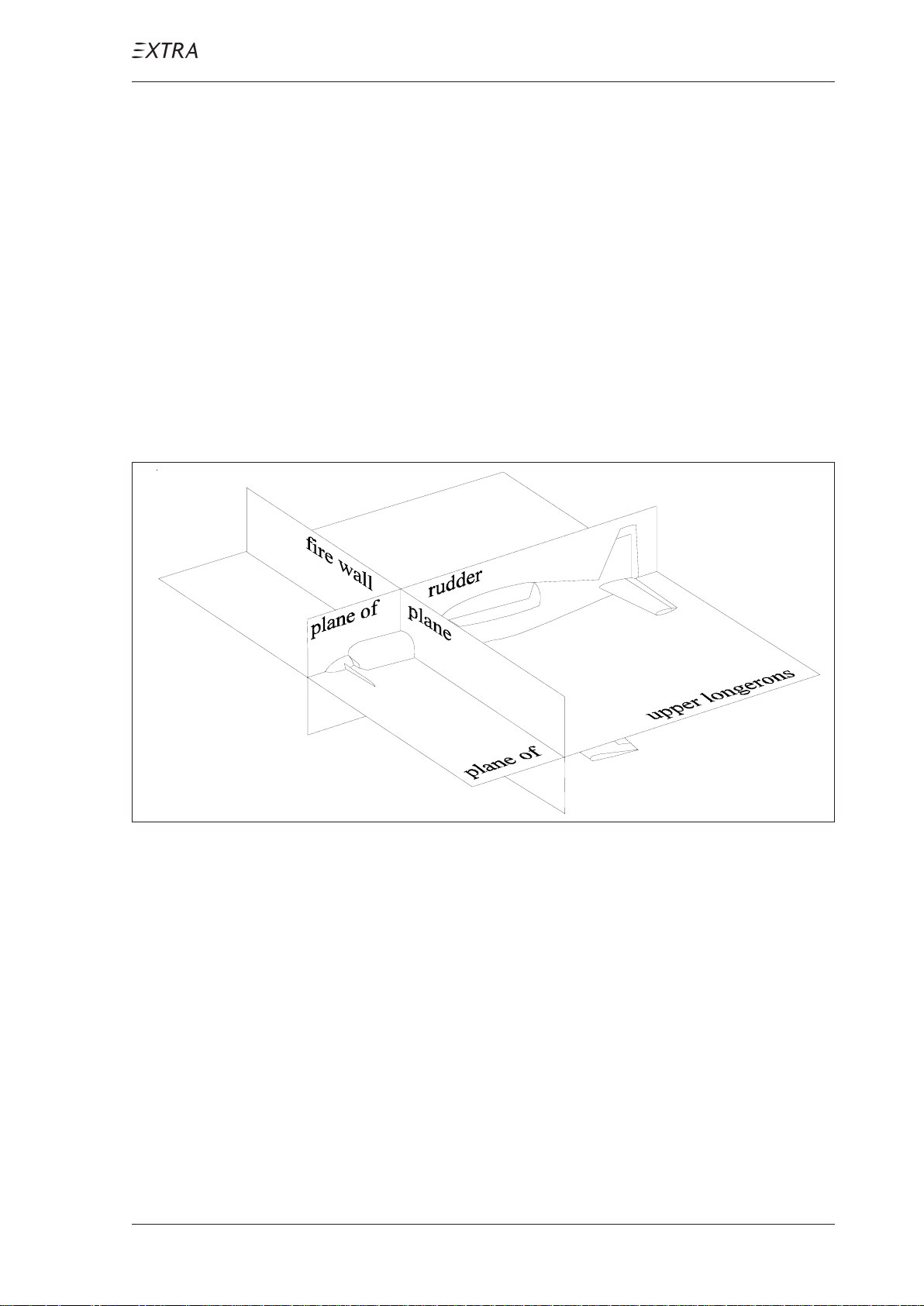
MAINTENANCE MANUAL EXTRA 300L T
06-00-00 GENERAL
The for measuring and weighing the aircraft relevant reference planes are the following:
Reference Planes
Plane of upper longerons (horizontal plane)
Plane of rudder (V ertical/symmetry plane)
Fire wall plane (V ertical plane)
The following figure1shows the aircraft reference planes:
Figure 1 Axes and Planes
Unless otherwise stated, all measurements given in this
manual are in metric (additional in feet) and are measured
parallel to the corresponding reference planes.
P AGE DA TE: 7. July 2010
CHAPTER 6
PAGE 3
Page 83
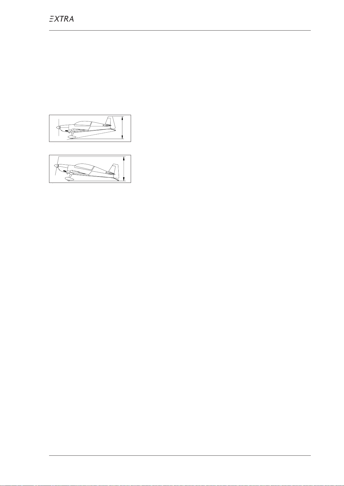
MAINTENANCE MANUAL EXTRA 300L T
06-10-00 MAIN DA T A
06-10-01 Main Dimensions
(Refer to figure 2 on page 6)
Length: 7.01 m (23.00 ft)
Height 1: 2.62 m (8.60 ft)
Height 1
Height 2
Height 2
: 2.59 m (8.45 ft)
Span: 8.00 m (26.25 ft)
Wheel base: 5.07 m (16.63 ft)
Wheel track: 1.80 m (5.91 ft)
MT O W : Normal category &
06-10-02 Wing
Span: 8.0 m (26.25 ft)
Area: 10.84 m² (116.68 ft²)
Airfoil: Root: NACA23015 (mod.)
Acro III category 950 kg(2095 lbs)
Acro II category 870 kg(1918 lbs)
Acro I category 820 kg(1808 lbs)
Tip: NACA23012 (mod.)
P AGE DA TE: 7. July 2010
Chord: Root: 1.88 m (6.17 ft)
Tip: 0.843 m (2.77 ft)
MAC: 1.427 m ( 4.682 ft)
Aileron area: 2 x 0.757 m² (2 x 8.15 ft²)
Aileron deflection: up 30°, down 20°, tolerance ± 2°
CHAPTER 6
PAGE 4
Page 84

MAINTENANCE MANUAL EXTRA 300L T
06-10-03 Horizontal T ail
Span: 3.20 m (10.50 ft)
Area: 2.55 m² (27.45 ft²)
Airfoil: Wortmann FX 71-L-150/30
06-10-04 Elevator
Area: 0.772 m² (7.77 ft²)
Elevator-deflection: up 25°, tolerance ± 2°
MAIN DATA
down 25°, tolerance - 2°
Trim-tab-deflection: up 35°, down 27°, tolerance ± 2°
06-10-05 Vertical T ail
Area: 1.38 m² (14.85 ft²)
Airfoil: Wortmann FX 71-L-150/30
06-10-06 Rudder
Area: 0.52 m² ( 5.60 ft²)
Rudder deflection: left 30°, right 30°, tolerance ± 2°
P AGE DA TE: 7. July 2010
PAGE DATE: 16. January 2009
CHAPTER 6
PAGE 5
Page 85
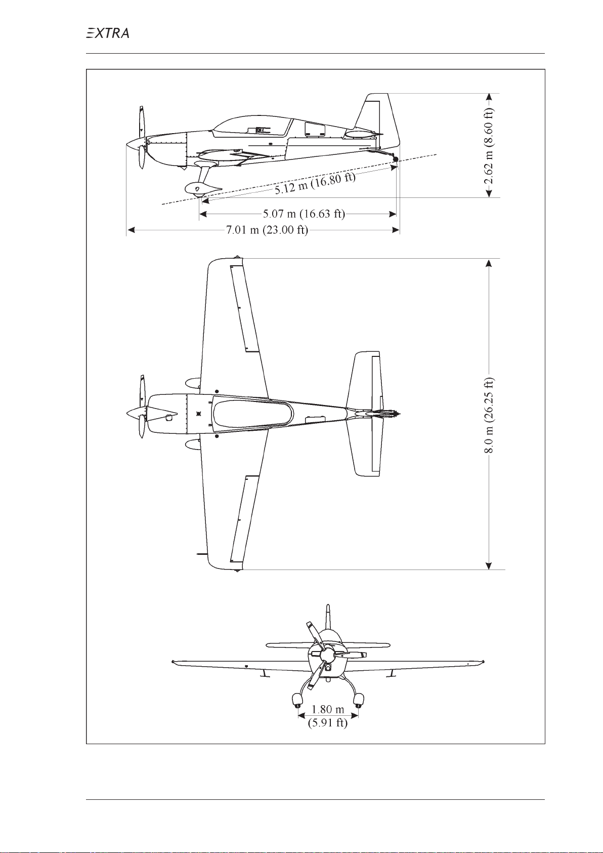
MAINTENANCE MANUAL EXTRA 300L T
MAIN DATA
Figure 2 Three-View EXTRA 300LT
P AGE DA TE: 7. July 2010
CHAPTER 6
PAGE 6
Page 86

MAINTENANCE MANUAL EXTRA 300L T
Chapter 7
Lifting and Shoring
P AGE DA TE: 7. July 2010
CHAPTER 7
PAGE 1
Page 87

MAINTENANCE MANUAL EXTRA 300L T
Table of Contents
Chapter/Figure Title
07-10-00 JACKING. . . . . . . . . . . . . . . . . . . . . . . . . . . . . . . . . . . 3
07-10-01 Balance Weight . . . . . . . . . . . . . . . . . . . . . . . . . . . . . . . 3
Figure 1 Balance Weight . . . . . . . . . . . . . . . . . . . . . . . . . . . . . . . 3
07-20-00 SHORING . . . . . . . . . . . . . . . . . . . . . . . . . . . . . . . . . . 4
07-20-01 Shoring the Front. . . . . . . . . . . . . . . . . . . . . . . . . . . . . . 4
Figure 2 Shoring the Front . . . . . . . . . . . . . . . . . . . . . . . . . . . . . 4
07-20-02 Shoring the Tail . . . . . . . . . . . . . . . . . . . . . . . . . . . . . . . 5
Figure 3 Shoring the Tail . . . . . . . . . . . . . . . . . . . . . . . . . . . . . . 5
P AGE DA TE: 7. July 2010
CHAPTER 7
PAGE 2
Page 88
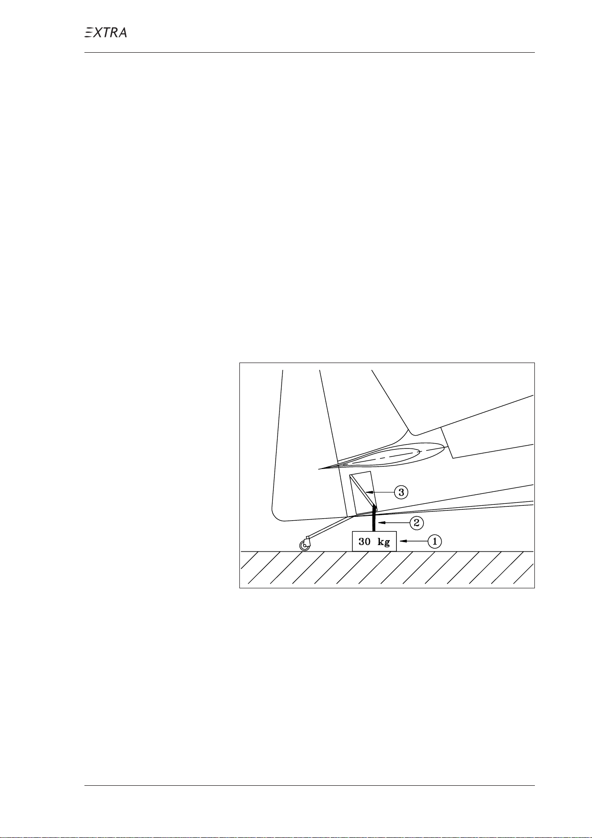
MAINTENANCE MANUAL EXTRA 300L T
07-10-00 JACKING
07-10-01 Balance Weight
Prior to the removal of the horizontal and/or vertical
stabilizer(s) or prior to shoring the aircraft as described in
chapter 07-20-00 it is necessary to weight the tail to prevent
aircraft from tilting onto the nose. In this case follow the
steps described below (refer to figure 1):
1 Put a weight (1) of min. 30 kg under the tail.
2 Remove the RH tail side skin and the tail cone access panel
as per chapter 51.
3 Connect the weight with the now accessible steel tube (3)
by means of a strap (2). Prevent damage of paint and control
cables.
P AGE DA TE: 7. July 2010
Figure 1 Balance Weight
CHAPTER 7
PAGE 3
Page 89
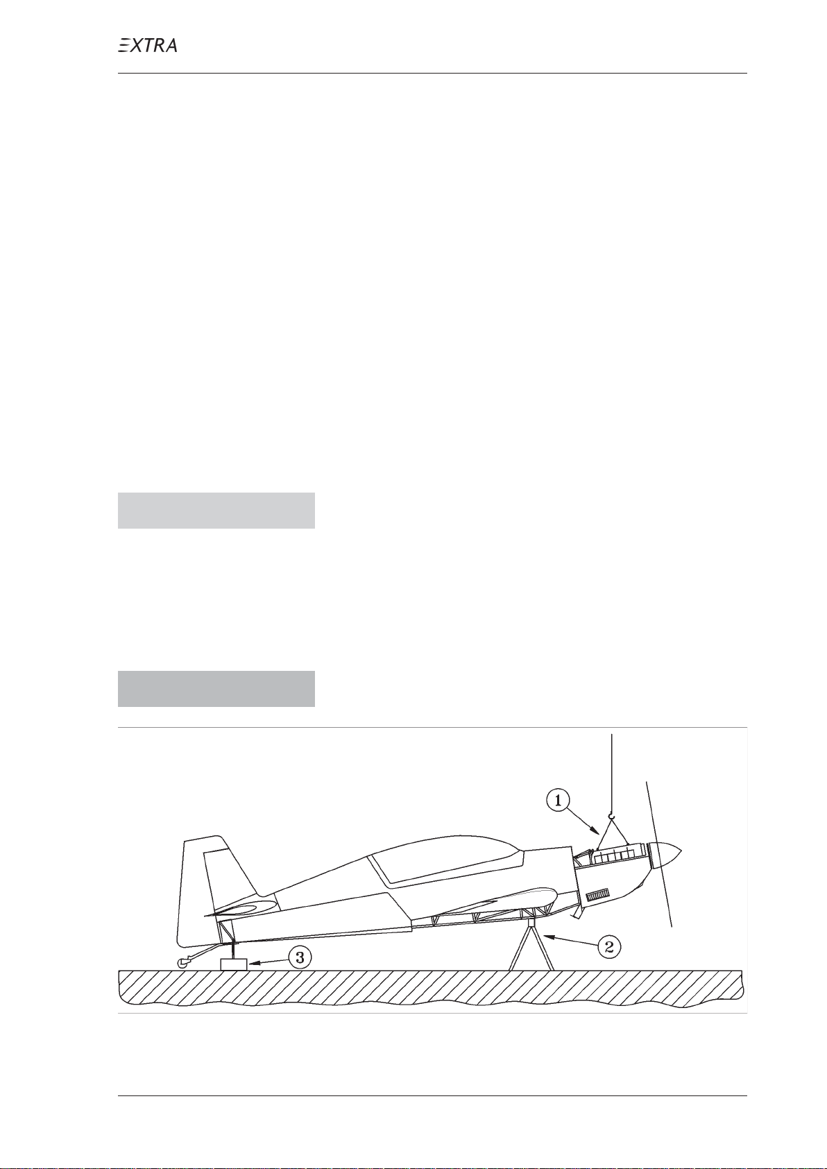
MAINTENANCE MANUAL EXTRA 300L T
07-20-00 SHORING
Shoring the Extra 300L T is necessary, when the main landing
gear or the tail wheel has to be removed or installed.
07-20-01 Shoring the Front
1 Remove the engine cowlings as per chapter 71 and the
bottom fuselage cover incl. cuffs as per chapter 53.
2 Install a balance weight (3, figure 2) at the tail as per chapter
07-10-01.
3 Hoist the aircraft by means of both engine hoisting points
(1).
C A U T I O N Prevent damage of ventilation tubing, brake lines and
drains, when shoring the aircraft.
4 Shore the aircraft by means of two supports (2), which are
to put under the left and right bottom longeron each in the
area behind the landing gear as shown in figure 2. This is
possible also, when the landing gear is installed.
W A R N I N G Maintain hoisting strap as a security device to prevent
nose over of the aircraft during maintenance work.
Figure 2 Shoring the Front
P AGE DA TE: 7. July 2010
CHAPTER 7
PAGE 4
Page 90
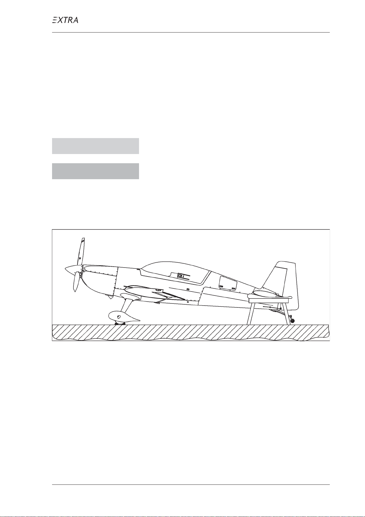
MAINTENANCE MANUAL EXTRA 300L T
07-20-02 Shoring the Tail
Refer to figure 3.
1 Secure the main wheels with wheel chocks.
2 Make available two approx. 2.5 feet high, approx. 1 foot wide
and approx. 3 feet long supports.
3 Cushion the supports.
C A U T I O N Don´t handle the elevator when lifting the tail.
W A R N I N G Do not lift the tail higher than necessary for support-
ing. The aircraft may tilt onto the nose.
4 Lift the tail some centimeters by handling carefully the hori-
zontal fins and put the cushioned supports under each side
of the horizontal stabilizer .
Figure 3 Shoring the T ail
P AGE DA TE: 7. July 2010
CHAPTER 7
PAGE 5
Page 91

MAINTENANCE MANUAL EXTRA 300L T
Chapter 8
Leveling and Weighing
P AGE DA TE: 7. July 2010
CHAPTER 8
PAGE 1
Page 92

MAINTENANCE MANUAL EXTRA 300L T
Table of Contents
Chapter/Figure Title
08-00-00 GENERAL . . . . . . . . . . . . . . . . . . . . . . . . . . . . . . . . . . 3
08-10-00 WEIGHING AND
CALCULATION OF C OF G . . . . . . . . . . . . . . . . . . . 4
08-20-00 LEVELING . . . . . . . . . . . . . . . . . . . . . . . . . . . . . . . . . 7
Figure 1 Leveling . . . . . . . . . . . . . . . . . . . . . . . . . . . . . . . . . . . . 7
P AGE DA TE: 7. July 2010
CHAPTER 8
PAGE 2
Page 93

MAINTENANCE MANUAL EXTRA 300L T
08-00-00 GENERAL
This chapter contains all information and procedures that are
necessary for weighing and leveling the EXTRA 300L T and
for determining the Center of Gravity .
W eigh the aircraft and determine the Center of Gravity each
5 years, after installation of additional equipment or after
repairs.
I M P O R T A N T Weigh, read the scales and calculate with carefulness.
Incorrect weighing or determination of Center of Gravity can endanger the pilot and the aircraft.
P AGE DA TE: 7. July 2010
CHAPTER 8
PAGE 3
Page 94

MAINTENANCE MANUAL EXTRA 300L T
08-10-00 WEIGHING AND
CALCULATION OF C OF G
N O T E Weigh the air craft only on even floor and in closed shops
(wind protected). Use three identical scales.
1 Ensure that the aircraft is fully equipped with equipment in
locations according to the equipment list (Pilot´s Operating
Handbook & Flight Manual (POH&FM), section 6.6).
N O T E Empty weight includes unusable fuel.
2 Defuel the aircraft (wing tanks, center and acro tank) to the
amount of unusable fuel.
3 Replenish engine oil to the minimum sump capacity for
acrobatic flight (refer to POH&FM section 1.7)
4 Remove foreign objects (e.g. tools, luggage, parachutes).
5 Clean and dry the aircraft.
6 Put the rear seat to middle position and close canopy .
7 Weigh two of those wheel chocks that will be used for se-
curing the main wheels. Enter the weight below in Page 5
"T are weight scale 1/2 (chocks)".
8 Weigh the jack that will be used for jacking the tail wheel.
Enter the weight below in Page 5 "T are weight scale 3 (jack)".
9 Roll the main wheels onto the scales 1 and 2.
10 Level the aircraft as per chapter 08-20-00.
11 Drop perpendiculars from the underside of the fire wall,
the centers of the main wheels and the tail wheel and mark
on the floor to get the arms X
and X2 (see page 6).
1
P AGE DA TE: 7. July 2010
12 Enter the arms on Page 6.
13 Read the scales and enter the weights below. Calculate the
net weights and transfer the values to page 6.
14 Calculate C of G using the formula given below (page 6).
CHAPTER 8
PAGE 4
Page 95

MAINTENANCE MANUAL EXTRA 300L T
WEIGHING
Gross weight scale 1
T are weight scale 1 (chocks) –
Net weight scale 1 (W
)
1
Gross weight scale 2
T are weight scale 2 (chocks) –
Net weight scale 2 (W
)
2
Gross weight scale 3
T are weight scale 3 (jack) –
Net weight scale 3 (W
)
3
. . . . . . . .
. . . . . . . .
. . . . . . . . .
. . . . . . . .
. . . . . . . .
. . . . . . . . .
. . . . . . . .
. . . . . . . .
. . . . . . . . .
kg
kg
kg
kg
kg
kg
kg
kg
kg
P AGE DA TE: 7. July 2010
CHAPTER 8
PAGE 5
Page 96
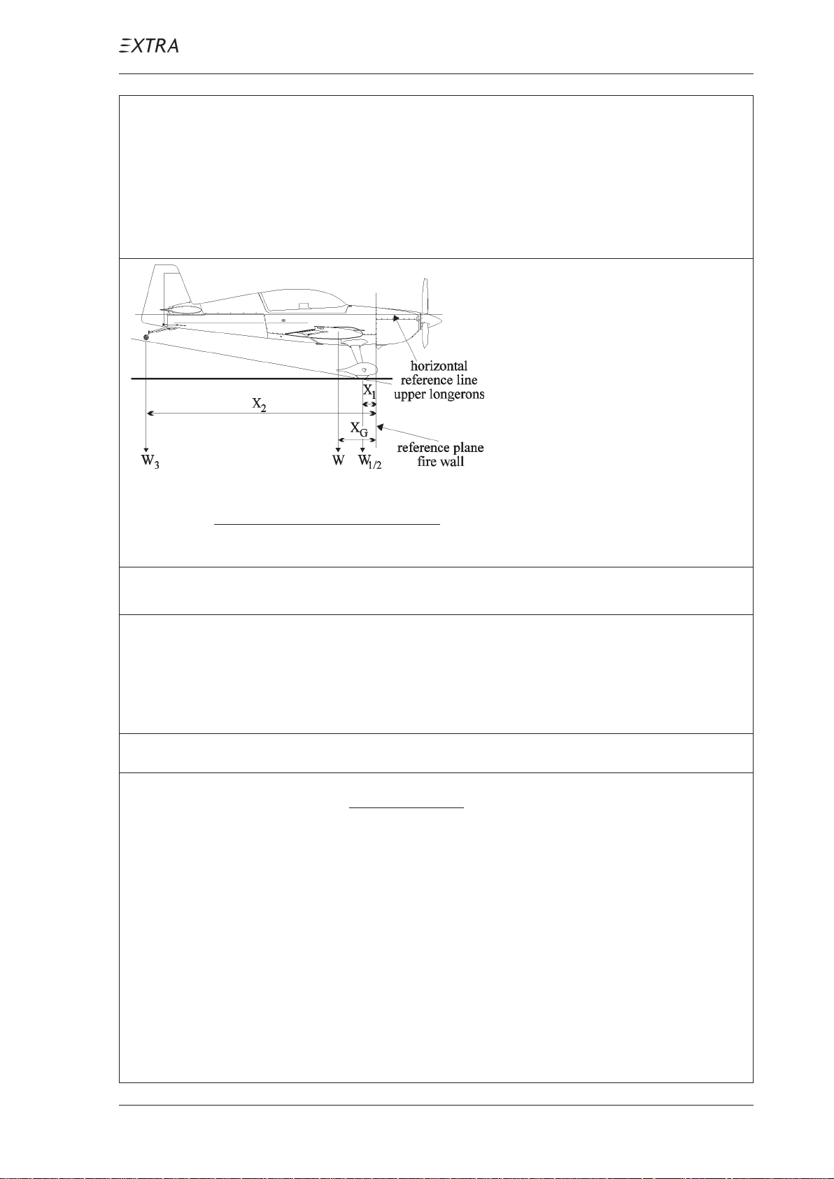
WEIGHING
MAINTENANCE MANUAL EXTRA 300L T
Empty Weight and Center of Gravity Position
EXTRA 300LT
Data according to "TC Data-Sheet" and "Pilot´s Operating Handbook and EASA approved
Airplane Flight Manual" Doc.-No.: EA - 0D701
Equipment according to Equipment List dated:
.
W
= W = W1 + W2 + W
X
G
+ W
X
1
1
2
W
.
X
+ W
1
.
X
3
. . . . . . . . . . . .
Legend:
X1= Arm: fire wall - main wheels
X2= Arm: fire wall - tail wheel
XG= Arm: fire wall - Center of Gravity
W1= Net weight main wheel LH
W2= Net weight main wheel RH
W3= Net weight tail wheel
W = Empty weight
2
Item W eight Arm Moment
Main wheel LH (W
)
. . . . . . . .
1
kg .(X1)
. . . . . . . .
cm =
. . . . . . . . . .
3
kgcm
Main wheel RH (W
Tail wheel (W
Empty weight (W)
)
. . . . . . . .
2
)
. . . . . . . .
3
. . . . . . . .
kg .(X1)
kg .(X2)
kg T otal moment
T otal moment
Empty weight
Empty weight is (W)
Center of Gravity is (X
W eighing performed by:
Aircraft Inspector:
* If value exceeds the given tolerances, contact the manufacturer.
P AGE DA TE: 7. July 2010
. . . . . . . . . .
)
. . . . . . . . . .
G
. . . . . . . . . . . . . .
. . . . . . . . . . . . . .
kg*.
cm aft fire wall.
. . . . . . . .
. . . . . . . .
= X
G
cm =
. . . . . . . . . .
cm =
. . . . . . . . . .
. . . . . . . . . . . . . .
W
: 646 kg
min
W
: 723 kg (Normal Cat.)
max
W
: 742 kg (Acro III)
max
W
: 662 kg (Acro II)
max
W
: 686 kg (Acro I)
max
Sign:
. . . . . . . . . . . . . .
CHAPTER 8
PAGE 6
kgcm
kgcm
kgcm
Page 97
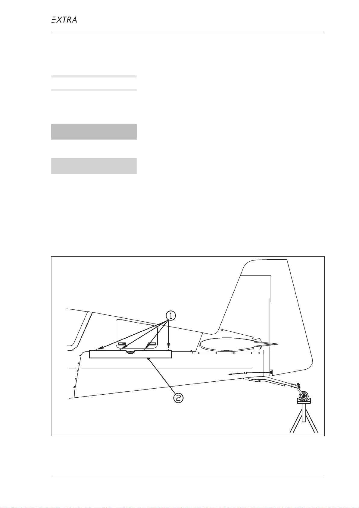
MAINTENANCE MANUAL EXTRA 300L T
08-20-00 LEVELING
N O T E Level the aircraft only on even floor and in closed shops
(wind protected).
1 Secure each main wheel with two wheel chocks.
W A R N I N G Do not lift tail wheel higher than necessary for leveling.
The aircraft may tilt onto the nose.
C A U T I O N Prior to levelling, ensure aircraft is clear of obstruc-
tions.
2 Lift tail and put the jack (height: ~90 cm (~3 ft)) under the
tail wheel, which has to be in the rearmost position.
3 Level the aircraft to its horizontal reference line using a
spirit level (2, figure 1), which is to put under the bolts of
the rear main fuselage cover (1). Adjust pitch by changing
the jack height.
Figure 1 Leveling
P AGE DA TE: 7. July 2010
CHAPTER 8
PAGE 7
Page 98

MAINTENANCE MANUAL EXTRA 300L T
Chapter 9
Towing and Taxiing
P AGE DA TE: 7. July 2010
CHAPTER 9
PAGE 1
Page 99

MAINTENANCE MANUAL EXTRA 300L T
Table of Contents
Chapter/Figure Title
09-00-00 GENERAL . . . . . . . . . . . . . . . . . . . . . . . . . . . . . . . . . . 3
09-10-00 TOWING . . . . . . . . . . . . . . . . . . . . . . . . . . . . . . . . . . . 3
09-20-00 TAXIING . . . . . . . . . . . . . . . . . . . . . . . . . . . . . . . . . . . 3
P AGE DA TE: 7. July 2010
CHAPTER 9
PAGE 2
Page 100

MAINTENANCE MANUAL EXTRA 300L T
09-00-00 GENERAL
This chapter describes the procedures and precautions
nescessary for proper ground handling of the EXTRA 300L T.
09-10-00 TOWING
D A N G E R When preparing for ground handling operation ensure
that the ignition switch is off.
The aircraft should be moved on the ground by hand without
using a towing vehicle or tow bar. For moving the aircraft on
the ground, push by hand the wing leading edges or pull at the
inboard portion of the propeller blades.
09-20-00 TAXIING
Taxiing the aircraft shall be performed by qualified personnel
only. All taxiing should be done at slow speed, and the
controls should be positioned such that the effects of gusty
wind are minimized.
C A U T I O N Taxiing over loose gravel or cinders should be done at
low engine speed to minimize damage to the airframe
surfaces due to stone damage.
The aircraft is taxiing as follows:
1 Start and warm engine up in accordance with the Pilot´s
Operating Handbook (PN: EA-0D701) section 4.3 "Starting Procedures".
C A U T I O N Only operate with the propeller at minimum blade an-
gle (High RPM).
P AGE DA TE: 7. July 2010
CHAPTER 9
PAGE 3
 Loading...