

Page 1
TITLE P AGE
I N F O R M A T I O N M A N U A L
E X T R A 2 0 0
MANUFACTURER
EXTRA Flugzeugproduktions- und Vertriebs- GmbH
Flugplatz Dinslaken
46569 Hünxe, Federal Republic of Germany
W A R N I N G
This is an Information Manual and may be used for general purposes only.
This Information Manual is not kept current.
It must not be used as a substitute for the official FAA/EASA Approved Pilot's Operating
Handbook required for operation of the airplane.
Page 2

Left blank intentionally
Page 3

Pilot´s Operating Handbook
EXTRA 200
MAIN TABLE OF CONTENTS
Section Page
0 PUBLICATION GUIDANCE .............................................................................................. 0-1
1 GENERAL......................................................................................................................... 1-1
2 LIMITATIONS ................................................................................................................... 2-1
3 EMERGENCY PROCEDURES......................................................................................... 3-1
4 NORMAL PROCEDURES ................................................................................................ 4-1
5 PERFORMANCE..............................................................................................................5-1
6 WEIGHT AND BALANCE AND EQUIPMENT LIST.......................................................... 6-1
7 DESCRIPTION AND OPERATION OF AIRCRAFT AND SYSTEMS................................7-1
8 HANDLING, SERVICING AND MAINTENANCE .............................................................. 8-1
9 SUPPLEMENTS ............................................................................................................... 9-1
Page Date: 20. April 2002 i
Page 4

THIS HANDBOOK SHALL ALWAYS BE CARRIED ON BOARD DURING FLIGHT.
Pilot´s Operating Handbook
EXTRA 200
PILOTS OPERATING HANDBOOK PREPARED
BY:
EXTRA Flugzeugproduktions- und Vertriebs- GmbH
THIS MANUAL IS FURNISHED TO
THE CIVIL AVIATION AUTHORITIES
AS A PART OF THE CERTIFICATIONMATERIAL FOR THIS MODEL.
ii Page Date: 20. April 2002
Page Date: 28. February 2006
Page 5

Pilot´s Operating Handbook
EXTRA 200
Publication Guidance
Section 0
SECTION 0
PUBLICATION GUIDANCE
Table of Contents
Paragraph Page
SECTION 0 PUBLICA TION GUIDANCE
1 INTRODUCTION................................................................................................................. 0-3
2 NOTES................................................................................................................................ 0-3
3 WARNINGS, CAUTIONS AND NOTES............................................................................... 0-4
4 LOG OF EFFECTIVE PAGES ............................................................................................. 0-5
Page Date: 20. April 2002 0 - 1
Page 6

Section 0
Publication Guidance
Pilot´s Operating Handbook
EXTRA 200
Left blank intentionally
0 - 2 Page Date: 20. April 2002
Page 7

Pilot´s Operating Handbook
EXTRA 200
Publication Guidance
Section 0
1 INTRODUCTION
This handbook contains 10 sections, and includes the material required to be furnished to
the pilot by FAR Part 23 . It also contains supplementary data supplied by EXTRA
Flugzeugproduktions- und Vertriebs- GmbH.
2 NOTES
2.1 This Flight Manual applies only to the aircraft whose nationality and registration marks are
noted on the title page.
2.2 It is the responsibility of the pilot to be familiar with the contents of this Flight Manual including revisions and any relevant supplements.
2.3 Pages of this Airplane Flight Manual must not be exchanged and no alterations of or additions to the approved contents may be made without the EXTRA Flugzeugproduktions- und
Vertriebs- GmbH/LBA approval.
The editor has the copyright of this Flight Manual and is responsible for edition of revisions/
amendments and supplements.
2.4 Amendments, which affect the airworthiness of the aircraft will be announced in the publication Lufttüchtigkeitsanweisung (airworthiness directive) issued by LBA, Luftfahrt-Bundesamt,
or by the manufacturer EXTRA Flugzeugproduktions- und Vertriebs- GmbH. The owner is
responsible for incorporating prescribed amendments and should make notes about these
on the records of amendments.
2.5 Should this Flight Manual get lost, inform EXTRA Flugzeugproduktions- und VertriebsGmbH, Dinslaken 46569 Hünxe, Federal Republic of Germany.
2.6 Should this Flight Manual be found, kindly forward it to the civil board of aviation in the
country the aircraft is registered.
2.7 This Flight Manual is only valid in connection with the latest, new LBA approved revision.
Page Date: 20. April 2002 0 - 3
Page Date: 28. February 2006
Page 8

Section 0
Publication Guidance
3 WARNINGS, CAUTIONS AND NOTES
The following definitions apply to Warnings, Cautions, and Notes:
=> Operating procedures, techniques, etc which could result in personal
injury or loss of life if not carefully followed
=> Operating procedures, techniques, etc , which could result in damage to
equipment if not carefully followed.
Pilot´s Operating Handbook
EXTRA 200
WARNING
CAUTION
NOTE
=> An operating procedures, technique, etc which is considered essential to
emphasize.
"Shall, "Will", "Should" and "May"
The words "Shall" or, "will" shall be used to express a mandatory
requirement. The word "should" shall be used to express nonmandatory
provisions. The word "may" shall be used to express permissible.
0 - 4 Page Date: 20. April 2002
Page 9

Pilot´s Operating Handbook
EXTRA 200
4 LOG OF EFFECTIVE PAGES
Publication Guidance
Section 0
Dates of issue for original and revised pages:
Original ................................. 29. May 1996
Revision No. 1 ............ 29. November 1996
Edition No. 2 .........................20. April 2002
Rev. No 1, 2nd Ed. ........28. February 2006
Rev. No 2, 2nd Ed. .... 20. September 2006
Rev. No 3, 2nd Ed. ............... 14. July 2008
Date and sign of LBA approval:
LBA approved...................12. August 1996
LBA approved............. 10. December 1996
LBA approved................. 30. October 2002
EASA Approval N° ...........EASA.A.A.01278
Date of Approval........ 05. September 2006
EASA Approval N° ...........EASA.A.A.01319
Date of Approval......... 20. November 2006
Approved under the authority of DOA
No.: EASA.21J.073 (ECO: ÄM-300-08-03)
Page Date: 14. July 2008
Page Date: 20. April 2002 0 - 5
Page 10

Section 0
Publication Guidance
LOG OF EFFECTIVE PAGES (cont.)
Pilot´s Operating Handbook
EXTRA 200
Page Date
Title ................................. 28. February 2006
i .............................................. 20. April 2002
ii....................................... 28. February 2006
0-1 thru 0-2............................. 20. April 2002
0-3 ................................... 28. February 2006
0-4 .......................................... 20. April 2002
0-5 thru 0-6.............................. 14. July 2008
1-1 ................................... 28. February 2006
1-2 .......................................... 20. April 2002
1-3 thru 1-5...................... 28. February 2006
1-6 .......................................... 20. April 2002
1-7 thru 1-8.............................. 14. July 2008
2-1 ........................................... 14. July 2008
2-2 .......................................... 20. April 2002
2-3 thru 2-4.............................. 14. July 2008
2-5 ................................... 28. February 2006
2-6 .......................................... 20. April 2002
2-7 ........................................... 14. July 2008
2-8 ................................20. September 2006
2-9 ........................................... 14. July 2008
2-10 ................................. 28. February 2006
2-11 thru 2-16.......................... 14. July 2008
3-1 thru 3-3............................. 20. April 2002
3-4 thru 3-5.............................. 14. July 2008
3-6 .......................................... 20. April 2002
3-7 ........................................... 14. July 2008
3-8 .......................................... 20. April 2002
4-1 ................................... 28. February 2006
4-2 .......................................... 20. April 2002
4-3 ........................................... 14. July 2008
4-4 thru 4-6............................. 20. April 2002
4-7 ........................................... 14. July 2008
4-8 ................................... 28. February 2006
4-9 ........................................... 14. July 2008
4-10 ........................................ 20. April 2002
4-11 ......................................... 14. July 2008
4-12 ........................................ 20. April 2002
5-1 thru 5-3............................. 20. April 2002
5-4 ........................................... 14. July 2008
5-5 .......................................... 20. April 2002
5-6 thru 5-9.............................. 14. July 2008
5-10 thru 5-11......................... 20. April 2002
5-12 ......................................... 14. July 2008
5-13 thru 5-14......................... 20. April 2002
5-15 thru 5-16.......................... 14. July 2008
Page Date
6-1 thru 6-2............................. 20. April 2002
6-3 ...................................28. February 2006
6-4 ..........................................20. April 2002
6-5 ...................................28. February 2006
6-6 thru 6-9............................. 20. April 2002
6-10 thru 6-14 ..................28. February 2006
7-1 ...................................28. February 2006
7-2 ..........................................20. April 2002
7-3 ...................................28. February 2006
7-4 thru 7-9............................. 20. April 2002
7-10 .................................28. February 2006
7-11 ........................................20. April 2002
7-12 thru 7-14 ..................28. February 2006
7-15 thru 7-16 .........................20. April 2002
8-1 thru 8-4............................. 20. April 2002
9-1 ...................................28. February 2006
9-2 ..........................................20. April 2002
9-3 ...................................28. February 2006
9-4 ..........................................20. April 2002
9.2-1 thru 9.2-10 (SN 1-2 only)20. April 2002
901-1 thru 901-4 .....................20. April 2002
902 .................................................reserved
903-1 thru 903-10 ...................20. April 2002
904-1 thru 904-6 .....................20. April 2002
905-1 thru 905-2 .....................20. April 2002
905-3 thru 905-4 ..............28. February 2006
905-5 thru 905-6 .....................20. April 2002
906-1 thru 906-6 .....................20. April 2002
907-1 thru 907-3 .....................20. April 2002
907-4 .......................................14. July 2008
907-5 thru 907-6 .....................20. April 2002
908-1 thru 908-2 .....................20. April 2002
908-3 thru 908-5 ......................14. July 2008
908-6 ......................................20. April 2002
909 thru 910 ...................................reserved
911-1 thru 911-4 .....................20. April 2002
912-1 thru 912-8 ..............28. February 2006
913-1 thru 913-8 ..............28. February 2006
914-1 thru 914-6 ..............28. February 2006
915-1 thru 915-8 ..............28. February 2006
916-1 thru 916-6 ..............28. February 2006
917-1 thru 917-8 ..............28. February 2006
918-1 thru 918-6 ..............28. February 2006
919-1 thru 919-8 ..............28. February 2006
920-1 thru 920-10 ............28. February 2006
0 - 6 Page Date: 20. April 2002
Page Date: 14. July 2008
Page 11

Pilot´s Operating Handbook
EXTRA 200
Section 1
General
SECTION 1
GENERAL
Table of Contents
Paragraph Page
SECTION 1 GENERAL
1.0 DESCRIPTION.................................................................................................................... 1-3
1.1 SPECIFICA TION OF CLASS .............................................................................................. 1-3
1.2 MANUFACTURER .............................................................................................................. 1-3
1.3 TECHNICAL DATA.............................................................................................................. 1-3
1.3.1 3-View Drawing ................................................................................................................... 1-3
1.3.2 Main Data............................................................................................................................ 1-4
1.3.3 Wing.................................................................................................................................... 1-4
1.3.4 Horizontal Tail ...................................................................................................................... 1-4
1.3.5 Elevator ............................................................................................................................... 1-4
1.3.6 Vertical Tail .......................................................................................................................... 1-4
1.3.7 Rudder ................................................................................................................................ 1-4
1.4 ENGINE .............................................................................................................................. 1-5
1.5 PROPELLER ...................................................................................................................... 1-5
1.5.1 Exhaust Systems (optional).................................................................................................1-5
1.6 FUEL................................................................................................................................... 1-5
1.7 OIL ......................................................................................................................................1-5
1.8 LOADING............................................................................................................................ 1-6
1.9 TERMINOLOGY ................................................................................................................. 1-6
1.10 SECONDARY TERMINOLOGY ..........................................................................................1-7
Page Date: 20. April 2002 1 - 1
Page Date: 28. February 2006
Page 12

Section 1
General
Pilot´s Operating Handbook
EXTRA 200
Left blank intentionally
1 - 2 Page Date: 20. April 2002
Page 13
Pilot´s Operating Handbook
EXTRA 200
1.0 DESCRIPTION
This description belongs to aircraft type EXTRA 200 with nationality and registration marks:
D - E J X A
Manufacturing
The airframe is built of tig-welded steel-tube construction. Wings, rudder and landing gear are
manufactured of composite material.
The aircraft is a two-seater with the rear seat instrumented for pilot in command.
1.1 SPECIFICATION OF CLASS
The aircraft is certified in normal and acrobatic category. LBA - Certificate No. 1086.
Section 1
General
1.2 MANUFACTURER
Manufacturer EXTRA Flugzeugproduktions- und Vertriebs- GmbH, Flugplatz Dinslaken,
46569 Hünxe, Federal Republic of Germany.
1.3 TECHNICAL DATA
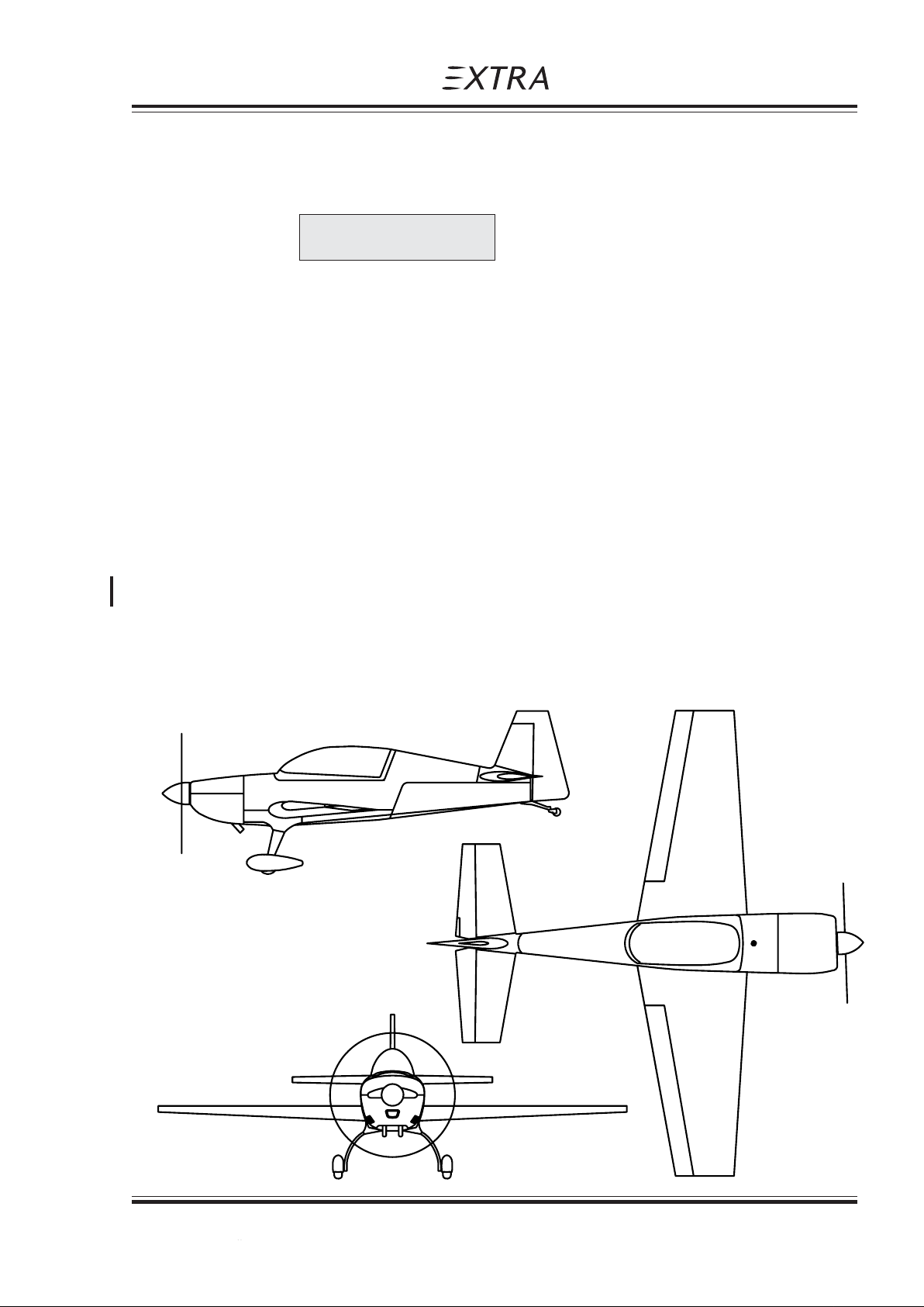
1.3.1 3-VIEW DRAWING
Page Date: 28. February 2006
Page Date: 20. April 2002 1 - 3
Page 14

Section 1
General
1.3.2 MAIN DATA
- Length 6,51 m (22,25 ft)
- Height 2,67m ( 8,76 ft)
- Span 7.50 m (24.61 ft)
- Wheelbase 1,80 m ( 5,91 ft)
- Wheel-track 4.91 m (16.10 ft)
1.3.3 WING
- Wing span 7.5 m (24.61 ft)
- Wing-area 10,44 m² (111.6 ft²)
- Airfoil Root: MA 15 S. Tip, MA 12 S
- Chord Root: 1,85 m. Tip, 0,93m
- MAC 1,39 m ( 4,56 ft)
- Aileron area 2 x 0,855 m² (2 x 9,20 ft²)
- Aileron deflection up 30°, down 30°, tolerance -2°
Pilot´s Operating Handbook
EXTRA 200
1.3.4 HORIZONTAL TAIL
- Span 3,20 m (10,50 ft)
- Area 2,56 m² (27.56 ft²)
- Airfoil Wortmann FX 71-L-150/30
1.3.5 ELEVATOR
- Area 0,77 m² (8,29 ft²)
- Elevator-deflection up 22°; down 22°; tolerance -2°
- Trim-tab-deflection > 15°,
1.3.6 VERTICAL TAIL
- Area 1,39 m² (14,96 ft²)
- Airfoil Wortmann FX 71-L-150/30
1.3.7 RUDDER
- Area 0,51 m² ( 5,49 ft²)
- Rudder deflection left 30°; right 30°; tolerance -2°
1 - 4 Page Date: 20. April 2002
Page Date: 28. February 2006
Page 15

Pilot´s Operating Handbook
EXTRA 200
1.4 ENGINE
Manufacturer: Textron-Lycoming Williamsport Plant PA 17701 USA.
Type: Textron Lycoming AEIO-360-A1E
Max. Takeoff Power: 200 HP @ 2700 RPM with full throttle in MSL
Max. Continuous Power 185 HP @ 2500 RPM with full throttle in MSL
1.5 PROPELLER
Manufacturer: MT-Propeller Entwicklung GmbH, Federal Republic of Germany.
Type: MTV-12-B-C/C183-17e 3-blade constant speed.
1.5.1 EXHAUST SYSTEMS (OPTIONAL)
Manufacturer: Gomolzig Flugzeug- und Maschinenbau GmbH, Federal Republic of Germany
Exhaust Silencer for Standard System: PN: EA 200-606000
Complete 4 in 1 System with integrated Silencer: PN: EA 200-606000/1
Section 1
General
1.6 FUEL
1.7 OIL
Sump capacity: 8 qts.
Minimum capacity for acro: 6 qts
Normal: 4 qts.
Fuel type AVGAS 100/100 LL (for alternate fuel grades see latest issue of Textron Lycoming
S.I. No 1070)
Total fuel capacity: 122 liters (32.1 US Gallon)
- Wingtanks (2 x 43 l) 86 liters (22.6 US Gallon)
- Acro tank 36 liters (9.5 US Gallon)
Usable fuel capacity: 117 L (30.8 US Gallon)
- Wingtanks: 85 L (22.4 US Gallon)
- Acro tank : 32 L (8.5 US Gallon)
Average ambient air Mil-L6082 Mil-22851
temperature grades ashless dispersant grades
All temperatures ---- SAE 15W50 or 20W50
> 27°C (80°F) SAE 60 SAE 60
> 16°C (60°F) SAE 50 SAE 40 or 60
- 1°C till 32°CSAE 40 SAE 40
(30°F - 90°F)
Page Date: 20. April 2002 1 - 5
Page Date: 28. February 2006
Page 16

Section 1
General
1.7 OIL (Cont.)
Average ambient air Mil-L6082 Mil-22851
temperature grades ashless dispersant grades
- 18°C till 21°C SAE 30 SAE 30, 40 or 20W40
(0°F - 70°F)
- 18°C till 32°C SAE 20W50 SAE 20W50 or 15W50
(0°F - 90°F)
< -12°C (10°F) SAE 20 SAE 30 or 20W30
(single or multi - viscosity aviation grade oils see latest issue of Textron Lyc. S.I. No. 1014)
1.8 LOADING
Wing loading 80.5 kg/m² Normal
Pilot´s Operating Handbook
EXTRA 200
67.0 / 76.6 kg/m² Acrobatic ( 1 seat / 2 seats )
Power loading 4.2 kg/hp Normal
1.9 TERMINOLOGY
Air Speeds
CAS Calibrated Air Speed. CAS is the same as TAS
KCAS Calibrated speed in knots
GS Ground speed
IAS Indicated air speed
KIAS Indicated speed in knots
TAS True air speed. It's the same as CAS compensated for altitude,
V
A
3.5 / 4.0 kg/hp Acrobatic ( 1 seat / 2 seats )
(True Air Speed) in standard atmospheric condition at sea level
temperature and density
Maneuvering speed
V
NE
V
NO
V
S
V
X
V
Y
1 - 6 Page Date: 20. April 2002
Never exceed speed
Maximum structural cruising speed
Stalling speed or minimum steady flight speed
Best angle-of-climb speed
Best rate-of-climb speed
Page 17

Pilot´s Operating Handbook
EXTRA 200
Meteorological terminology
ISA International standard atmospheric condition
OAT Outside air temperature
1.10 SECONDARY TERMINOLOGY
FPM Feet/minute
ft Feet = 0.3048 m
inch inch = 2.54 cm
m Meter
L Liters
Gal US gallon = 3.79 liters
Section 1
General
Qts US quart = 0.946 liters
hp Horse power (english)
h Hour
kts Knots (NM/h) = 1.852 kilometer per hour
km/h kilometer per hour
Lbs English pound = 0.4536 kg
hPA hekto Pascal
IN HG Inches of mercury
MP Manifold pressure
PA Pressure altitude (ft)
NM Nautical miles = 1.852 km
RPM Revolutions per minute
C.G. Center of gravity
Arm Arm is the horizontal distance from reference datum
Moment is the product of weight of an item multiplied by its arm.
Page Date: 20. April 2002 1 - 7
Page Date: 14. July 2008
Page 18
Section 1
General
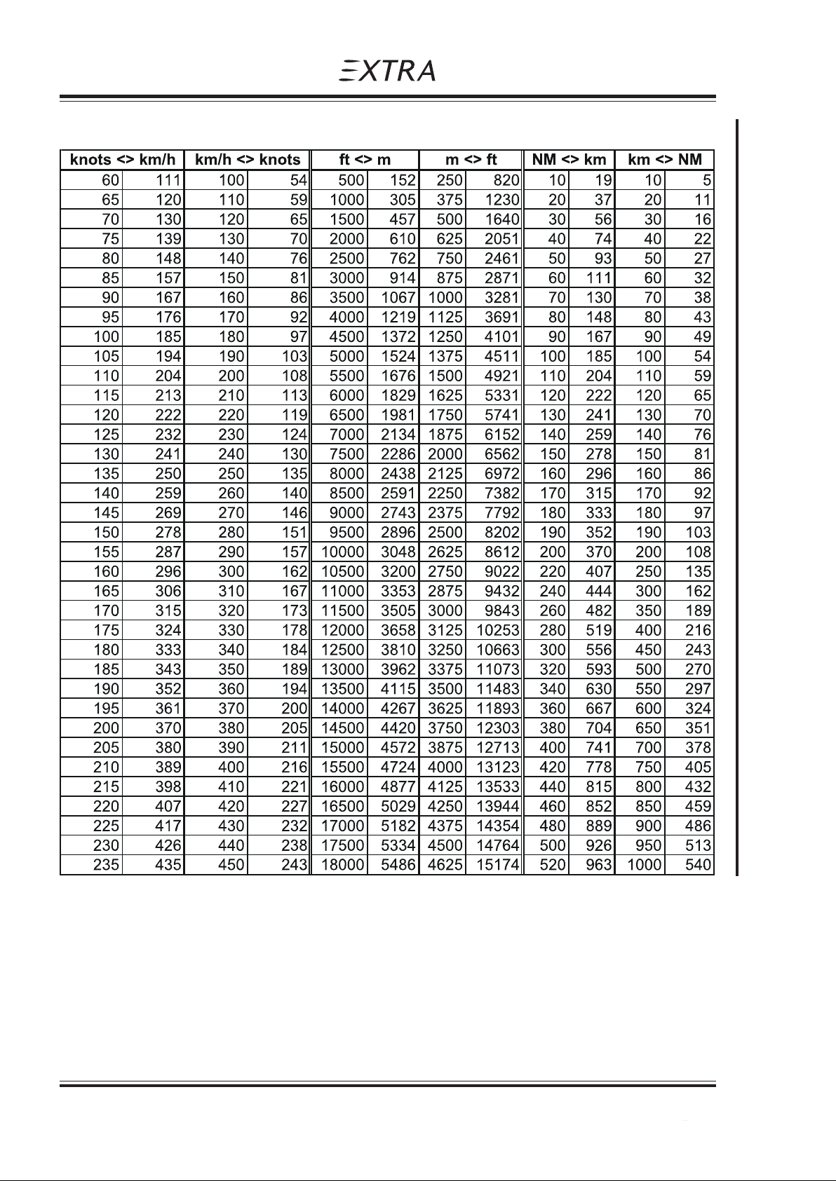
1.11 CONVERSION TABLE
Pilot´s Operating Handbook
EXTRA 200
1 - 8 Page Date: 20. April 2002
Page Date: 14. July 2008
Page 19

Pilot´s Operating Handbook
EXTRA 200
Section 2
Limitations
SECTION 2
LIMITATIONS
Table of Contents
Paragraph Page
SECTION 2 LIMIT A TIONS
2.1 GENERAL ........................................................................................................................... 2-3
2.2 AIR SPEED (IAS) ................................................................................................................2-3
2.3 CROSSWIND COMPONENT.............................................................................................. 2-3
2.4 ENGINE .............................................................................................................................. 2-3
2.4.1 Fuel ..................................................................................................................................... 2-4
2.4.2 Engine Limitations ............................................................................................................... 2-4
2.5 PROPELLER ...................................................................................................................... 2-5
2.6 WEIGHT LIMITS................................................................................................................. 2-5
2.7 WEIGHT AND C.G . ENVELOPE ......................................................................................... 2-5
2.7.1 Normal Flight....................................................................................................................... 2-5
2.7.2 Acrobatic Flight (1 Seat)......................................................................................................2-5
2.7.3 Acrobatic Flight (2 Seats) .................................................................................................... 2-5
2.8 ACROBA TIC MANEUVERS................................................................................................ 2-6
2.8.1 Normal Flight....................................................................................................................... 2-6
2.8.2 Acrobatic Flight.................................................................................................................... 2-6
2.9 LOAD F ACTOR................................................................................................................... 2-7
2.9.1 Normal Flight....................................................................................................................... 2-7
2.9.2 Acrobatic Flight.................................................................................................................... 2-8
2.10 FLIGHT CREW LIMITS ...................................................................................................... 2-8
2.1 1 KINDS OF OPERA TIONAL LIMITS .................................................................................... 2-8
2.1 1.1 Structural Temperature/Colour Limitation.............................................................................2-8
2.12 MAXIMUM OPERA TING AL TITUDE ................................................................................... 2-8
2.13 TIRE PRESSURE ............................................................................................................... 2-8
2.14 MARKINGS AND PLACARDS............................................................................................ 2-8
2.14.1 Aircraft Identity Placard ....................................................................................................... 2-8
2.14.2 Operating Placards.............................................................................................................. 2-9
2.14.3 Instrument Markings.......................................................................................................... 2-14
2.15 KINDS OF OPERATION EQUIPMENT LIST..................................................................... 2-15
2.16 NOISE LEVEL................................................................................................................... 2-16
Page Date: 20. April 2002 2 - 1
Page Date: 14. July 2008
Page 20

Section 2
Limitations
Pilot´s Operating Handbook
EXTRA 200
Left blank intentionally
2 - 2 Page Date: 20. April 2002
Page 21

Pilot´s Operating Handbook
EXTRA 200
2.1 GENERAL
This section includes operating limitations, instrument markings, and basic placards necessary for the safe operation of the aircraft, its engine, standard systems, and standard equipment. The limitations included in this section have been approved by the LuftfahrtBundesamt (LBA). Observance of these operating limitations is required by national aviation
regulations.
In case of an aircraft equipped with specific options additional information required for safe
operation will be contained in Section 9 "Supplements".
SECTION 2
LIMITATIONS
N O T E
NOTE
Section 2
Limitations
Instrument markings and placards are provided for the acrobatic category only; for normal
category refer to corresponding limitations. This aircraft is certified under
LBA-Flugzeugkennnblatt No. 1086, Type Certification Data Sheet (T.C.D.S.).
Any exceeding of given limitations have to be reported by the pilot and considered by
corresponding maintenance or inspection procedure according to the SERVICE MANUAL .
2.2 AIR SPEED (IAS)
Never Exceed Speed V
Max. Structural Cruising Speed V
Maneuver Speed (Normal Cat.) V
Maneuver Speed (Acro I , Acro II) V
2.3 CROSSWIND COMPONENT
Max. demonstrated crosswind component for takeoff
and landing 15 knots (27 km/h).
217 KIAS (402 km/h)
NE
154 KIAS (285 km/h)
NO
138 KIAS (256 km/h)
A
154 KIAS (285 km/h)
A
2.4 ENGINE
Engine-type: Textron-Lycoming AEIO-360-A1E with
Max. Takeoff Power: 200 HP @ 2700 RPM with full throttle in MSL
Max. Continuous Power 185 HP @ 2500 RPM with full throttle in MSL
Page Date: 14. July 2008
Page Date: 20. April 2002 2 - 3
Page 22

Section 2
Limitations
2.4.1 FUEL
Minimum grade aviation gasoline : 100/100LL; for alternate fuelgrades see latest revision of
Lyc. S.I. No. 1070
Total fuel capacity: 122 litres (32.1 US Gallon)
Usable fuel capacity: 117 litres (30.8 US Gallon)
For acrobatic flight wing tanks must be empty.
Total fuel capacity for acrobatic 36 litres (9.5 US Gallon) in acro tank.
Usable fuel capacity for acrobatic 32 litres (8.5 US Gallon) in acro tank.
2.4.2 ENGINE LIMITATIONS
a) Power in MSL
-Max. Takeoff Power: 200 HP @ 2700 RPM with full throttle
-Max. Continuous Power:185 HP @ 2500 RPM with full throttle
b) Oil-temperature gauge
-Max 118°C 245°F
Pilot´s Operating Handbook
EXTRA 200
c) Oil capacity
-Maximum sump capacity: 8 qts.
-Minimum sump capacity: -Acrobatic: 6 qts.
-Normal: 4 qts.
d) Oil pressure
-Minimum Idling 172 kPa 25 Psi
-Normal 414 - 621 kPa 60 - 90 Psi
-Starting, Warm up,
Taxi and Takeoff 379 - 689 kPa 55-100 Psi
C A U T I O N
It is normal for the oil pressure to "flicker" from 10 to 30 psi (69 to 207 kPa) when going from
upright to inverted flight. During knife edge flights and zero-g flights oil pressure may drop
and the oil system may not scavenge resulting in engine failure or damage if flight is
prolonged. Knife edge and zero-g flight should not exceed 10 seconds.
W A R N I N G
If oil pressure drops to 0 psi the propeller pitch changes automatically to coarse (high) pitch
with a corresponding decrease in RPM. Apply positive g to avoid engine stoppage.
e) Fuel pressure
- Max. 83 kPa 12 Psi
f) Cylinder head temperature
- Max 260°C 500°F
2 - 4 Page Date: 20. April 2002
Page Date: 14. July 2008
Page 23

Pilot´s Operating Handbook
EXTRA 200
2.5 PROPELLER
MT-Propeller Entwicklung GmbH, Federal Republic of Germany
Type: MTV-12-B-C/C183-17e
Max. Takeoff RPM: 2700
Max. Continuous RPM: 2500
2.6 WEIGHT LIMITS
Max. allowed empty weight:
-Normal category 646 kg (1424lbs)
-Acrobatic category ( 1 seat) 591 kg (1302lbs)
Max. allowed T/O weight:
-Normal category 840 kg (1858 lbs)
-Acrobatic category ( 1 seat) 700 kg (1549 lbs)
Section 2
Limitations
( 2 seats) 606 kg (1335lbs)
( 2 seats) 800 kg (1770 lbs)
Max. allowed landing weight: 840 kg (1858 lbs)
2.7 WEIGHT AND C.G. ENVELOPE
Vertical reference = firewall.
Horizontal reference = upper longerons in cockpit.
2.7.1 NORMAL FLIGHT
Max T/O Weight: forward C.G. rear C.G.
840 kg (1858 lbs) 73,2 cm (28,8") 89.1 cm (35.0")
(and below)
2.7.2 ACROBATIC FLIGHT (1 SEAT)
Max T/O Weight: forward C.G. rear C.G.
700 kg (1549 lbs) 73,2 cm (28,8") 89.1 cm (35.0")
(and below)
2.7.3 ACROBATIC FLIGHT (2 SEATS)
Max T/O Weight: forward C.G. rear C.G.
800 kg (1770 lbs) 73,2 cm (28,8") 89.1 cm (35.0")
(and below)
Page Date: 28. February 2006
Page Date: 20. April 2002 2 - 5
Page 24

Section 2
Limitations
2.8 ACROBATIC MANEUVERS
2.8.1 NORMAL FLIGHT
All acrobatic maneuvers are prohibited except stall, chandelle, lazy eight and turns up to 60
degrees bank angle.
2.8.2 ACROBATIC FLIGHT
The plane is designed for unlimited acrobatics within the approved operating limitations.
Inverted flight manoeuvers are limited to max 4 min. Recommended basic maneuver entry
speeds are listed in the following list.
If acrobatic maneuvers will be performed with copilot or passenger, the pilot has to check
and attend the physiological capability before and during acrobatic maneuvers due to the
high possible g-loads.
NOTE
N O T E
Pilot´s Operating Handbook
EXTRA 200
Check weight and C.G.position !
2 - 6 Page Date: 20. April 2002
Page 25
Pilot´s Operating Handbook
EXTRA 200
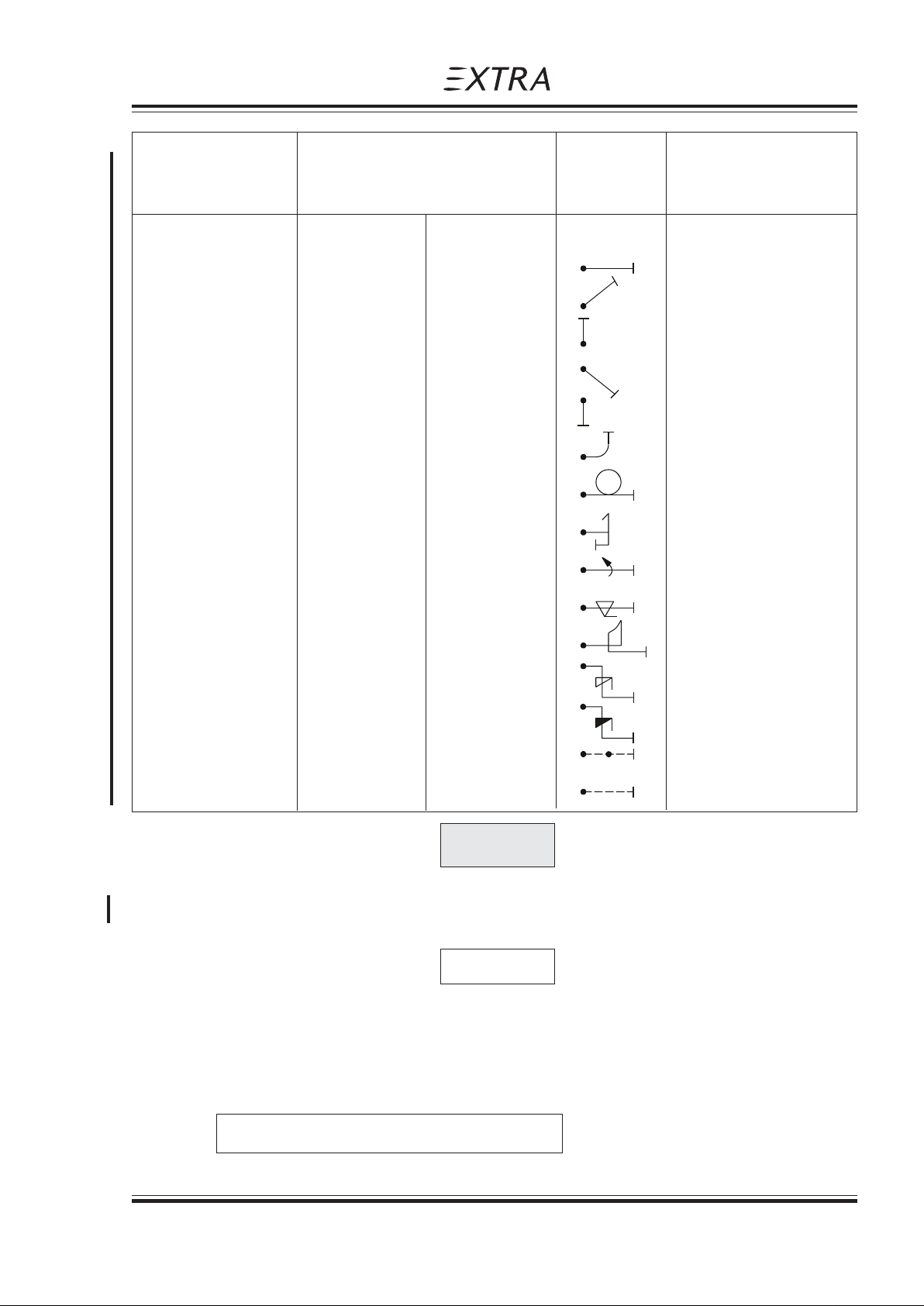
Recommended entry speeds IAS
Maneuvers Symbol Remarks
min knots (km/h) max knots (km/h)
Segment:
Section 2
Limitations
horizontal Line V
S
45°climbing 80 (148) V
90° up V
45° diving V
90° diving V
A
S
S
V
V
< V
< V
NE
NE
NE
NE
NE
1/4 Loop climb. 100 (185) 185 (343)
Looping 100 (185) 185 (343)
Stall turn 100 (185) 185 (343)
Aileron roll 80 (148) V
A
Snap roll 80 (148) 135 (250)
"tail slide" 100 (185) 185 (343)
Spin V
Inverted Spin V
S
S
reduce throttle
reduce throttle
full deflection
Knife edge >150 (278) < 10 s
Inverted Flight >V
S
185 (343) < 4 min
CAUTION
Particular caution must be exercised when performing maneuvers at speeds above
VA [154 KIAS (285 km/h)]. Large or abrupt control inputs above this speed may impose
unacceptably high loads which exceed the structural capability of the aircraft.
NOTE
For Acrobatic Maneuvers see Section 4. All maneuvers can be performed in upright and
inverted flight attitude.
2.9 LOAD FACTOR
2.9.1 NORMAL FLIGHT
+ 6 g / - 3 g for MTOW: 840 kg (1852 lbs)
Page Date: 20. April 2002 2 - 7
Page Date: 14. July 2008
Page 26
Section 2
Limitations
2.9.2 ACROBATIC FLIGHT
+ 10 g / - 10 g for 1 seat occupied (MTOW 700 kg / 1543 lbs)
+ 8 g / - 8 g for 2 seat occupied (MTOW 800 kg / 1763 lbs)
2.10 FLIGHT CREW LIMITS
Minimum crew is one pilot in the rear seat. 2 persons in both categories (Normal and Acrobatic).
Pilot in command seat is the rear seat, Copilot or passenger seat is the front seat. Noise
optimized headsets are required.
2.11 KINDS OF OPERATIONAL LIMITS
Only VFR flights at day are allowed. The A/C engine may be started on ground at OAT from
-20°C (-4°F) to +44°C (+111°F). Below temperatures of -10°C (+14°F) the oil vent line must be
modified by the low temperature kit (breather line). Flight in known icing-conditions is prohibited.
Smoking is prohibited.
Pilot´s Operating Handbook
EXTRA 200
2.11.1 STRUCTURAL TEMPERATURE/COLOUR LIMITATION
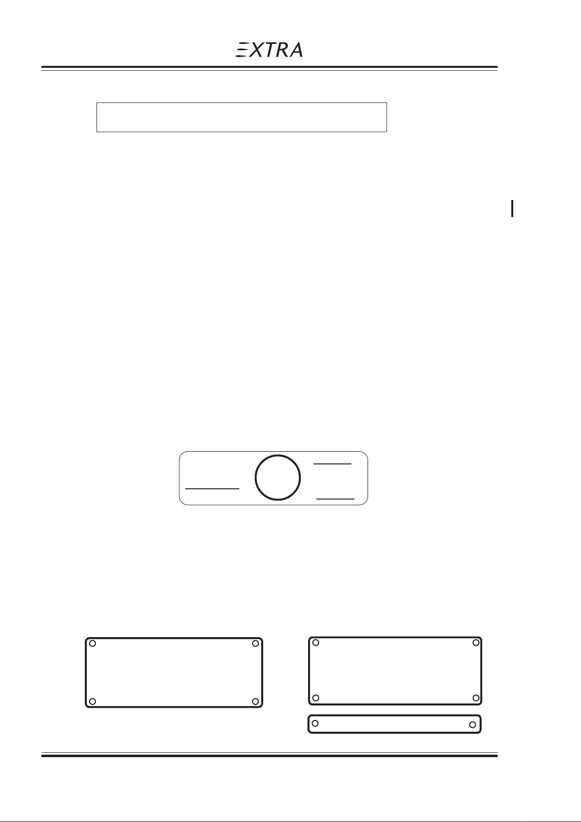
Structure is qualified up to 72°C (161.6°F). Structure temperatures (composite) above 72°C
(161.6°F) are not permitted. Not to exceed this temperature limit, colour specification for
composite structure (manufacturer document EA-03205.19) has to be complied with.
To check the temperature inside the cockpit (potential "green house" effect) a reversible
temperature indicator (STRUCTURAL OVERHEAT INDICATOR) is applied on the root rib of the
right wing. After reaching the temperature limit of 72°C (161,6°F) the word "RISK" appears and
flying is prohibited.
STRUCTURAL
OVERHEAT
INDICATOR
EXTRA
RISK
CAUTION:
While the word
appears, flying
is prohibited !
2.12 MAXIMUM OPERATING ALTITUDE
Max. certified operating altitude is 16000 ft MSL (4877 m)
2.13 TIRE PRESSURE
The tire pressure is 2,6 bar (37,7 Psi).
2.14 MARKINGS AND PLACARDS
2.14.1 AIRCRAFT IDENTITY PLACARD
RISK
MANUFACTURER:
EXTRA FLUGZEUGBAU GmbH
or
MODEL: EA 200
SERIAL NUMBER:______
FLUGZEUGPRODUKTIONSUND VERTRIEBS-GMBH
MODEL: EA 300/200
SERIAL NUMBER:
EXTRA
TC-NUMBER:
TC-NUMBER: A67EU
2 - 8 Page Date: 20. April 2002
Page Date: 20. September 2006
Page 27

Pilot´s Operating Handbook
EXTRA 200
2.14.2 OPERATING PLACARDS
Section 2
Limitations
VA = 154 KIAS (Acro) VA = 285 km/h (Acro)
VA = 138 KIAS (Normal) VA = 256 km/h (Normal)
or
(near airspeed indicator)
THE MARKINGS AND PLACARDS INSTALLED IN (in the rear cockpit)
THIS AIRPLANE CONTAIN OPERATING LIMITATIONS
WHICH MUST BE COMPLIED WITH WHEN OPERATING
THIS AIRPLANE IN THE ACROBATIC CATEGORY.
OTHER LIMITATIONS WHICH MUST BE COMPLIED
WITH WHEN OPERATING THIS AIRPLANE IN THIS
CATEGORY OR IN THE NORMAL CATEGORY ARE
CONTAINED IN THE AIRPLANE FLIGHT MANUAL.
APPLICABLE RPM LIMITATION MUST BE OBSERVED.
THIS AIRPLANE IS CERTIFICATED (on the rear instrument panel)
FOR VFR, DAY OPERATION.
OPERATION IN KNOWN ICING
CONDITIONS IS PROHIBITED.
F U E L (near each O I L (on the separate
AVGAS 100/100 LL filler cap) hatch / upper cowling)
FUEL SELECTOR VALVE
WING TANKS
usable 85 L(22.4 US GAL)
(in both cockpits near selector valve
ACRO &
CENTER
TANK
usable 32 L
(8.5 US GAL)
OFF
NOSE DOWN <= NEUTRAL=> NOSE UP (near the handle at the right side
TRIM in the rear cockpit)
WING TANK (on the rear instrument panel under the
MUST BE EMPTY FOR ACROBATICS fuel capacity indicators )
ACRO & CENTER TANK
WHEN THE INDICATOR READS "ZERO" IN LEVEL FLIGHT THE
REMAINING USABLE FUEL IS 8 LITERS (2 US GAL.)
handle)
Page Date: 20. April 2002 2 - 9
Page Date: 14. July 2008
Page 28

Section 2
Limitations
Pilot´s Operating Handbook
EXTRA 200
ACROBATIC: ± 10 G, 1 PILOT ± 8 G, 2 PERSON ON BOARD
MTOW: 700 KG (1543 LBS) MTOW: 800 KG (1763 LBS)
NORMAL: + 6 G/ -3 G; MTOW: 840 KG (1852 LBS) (in both cockpits)
ACROBATICS INCL. SPIN NOT APPROVED
AUXILIARY FUEL PUMP (near pump-switch on the instrument panel
in the rear cockpit)
ON OFF
NO SMOKING (in both cockpits)
USE OF HEADSET IS REQUIRED (on the right side of both
USE OF PARACHUTE IS RECOMMENDED instrument panels)
NO BAGGAGE
MAGNETIC (near Mag. Dir. Indicator)
DIRECTION INDICATOR
CALIBRATION
LOW RPM <= PROP => HIGH RPM (on RPM control unit in the
rear cockpit)
LEAN <= MIXTURE => RICH (on mixture control unit in the
rear cockpit)
CLOSE <= THROTTLE => OPEN (near throttle control in both
cockpits)
LOCK <= CANOPY => UNLOCK (near canopy locking handles
of each cockpit)
VENT
(near the eyeballtype adjustable vents)
PITOT-STATIC
DRAIN
(near the drain-point)
OPEN
2 - 10 Page Date: 20. April 2002
Page Date: 28. February 2006
Page 29

Pilot´s Operating Handbook
EXTRA 200
APPROVED ACROBATIC MANEUVERS
AND RECOMMENDED ENTRY AIRSPEEDS
MANEUVERS SPEEDS
Segment:
horizontal Line V
min KIAS max KIAS
S
V
NE
Section 2
Limitations
45°climbing 80 V
90° up V
45° diving V
90° diving V
A
S
S
V
<V
<V
NE
NE
1/4 Loop climb. 100 185
Loop 100 185
Stall turn 100 185
Aileron roll 80 V
A
Snap roll 80 138
"Tail-slide" 100 185
Spin V
S
NE
NE
Inverted spin V
Inverted flight > V
S
S
185
Less than 4 min
Knife edge >150
Less than 10 s
CAUTION
Particular caution must be exercised when performing
maneuvers at speeds above VA (154 KIAS). Large or
abrupt control inputs above this speed may impose
unacceptably high loads which exceed the structural
WARNING:
SOLO FLYING FROM
(on front instrument panel)
REAR SEAT ONLY!
(in both cockpits)
(alternative SI units
next page)
Page Date: 20. April 2002 2 - 11
Page Date: 14. July 2008
Page 30

Section 2
Limitations
APPROVED ACROBATIC MANEUVERS
AND RECOMMENDED ENTRY AIRSPEEDS
MANEUVERS AIRSPEEDS
min km/h max km/h
Segment:
horizontal Line V
S
Pilot´s Operating Handbook
V
NE
EXTRA 200
45°climbing 148 V
90° up V
45° diving V
90° diving V
A
S
S
V
<V
<V
NE
NE
1/4 Loop climb. 185 343
Loop 185 343
Stall turn 185 343
Aileron roll 148 V
A
Snap roll 148 256
"Tail-slide" 185 343
Spin V
S
NE
NE
Inverted spin V
Inverted flight > V
S
S
343
Less than 4 min
Knife edge >278
Less than 10 s
CAUTION
Particular caution must be exercised when performing
maneuvers at speeds above VA (285 km/h). Large or
abrupt control inputs above this speed may impose
unacceptably high loads which exceed the structural
(in both cockpits)
(alternative US units
previous page)
2 - 12 Page Date: 20. April 2002
Page Date: 14. July 2008
Page 31

Pilot´s Operating Handbook
EXTRA 200
Section 2
Limitations
Left blank intentionally
Page Date: 14. July 2008
Page Date: 20. April 2002 2 - 13
Page 32

Section 2
Limitations
2.14.3 INSTRUMENT MARKINGS
AIRSPEED INDICATOR
green arc 60 KIAS (111 km/h) - 154 KIAS (285 km/h)
yellow arc 154 KIAS (285 km/h) - 217 KIAS (402 km/h)
red line 217 KIAS (402 km/h)
OIL PRESSURE INDICATOR
red line 25 Psi (172 kPa)
yellow arc 25 Psi (172 kPa) - 55 Psi (379 kPa)
green arc 55 Psi (379 kPa) - 90 Psi (621 kPa)
yellow arc 90 Psi (621 kPa) - 100Psi (689 kPa)
red line 100 Psi (689 kPa)
OIL TEMPERATURE INDICATOR
yellow arc <140°F
green arc 140°F - 210°F
yellow arc 210°F - 245°F
red line 245°F
Pilot´s Operating Handbook
EXTRA 200
CYLINDERHEAD TEMPERATURE INDICATOR
yellow arc <150°F
green arc 150°F - 400°F
yellow arc 400°F - 500°F
red line 500°F
RPM INDICATOR
green arc 700 - 2500 RPM
yellow arc 2500 - 2700 RPM
red line 2700 RPM
G - METER
green arc - 5 g - + 8 g
yellow arc + 8 g - + 10 g
red line + 10 g
FUEL PRESSURE INDICATOR
red line 0 PSI
green arc 0 PSI - 12 PSI
red line 12 PSI
FUEL CAPACITY INDICATOR "WING TANK"
red line 0
FUEL CAPACITY INDICATOR "ACRO & CENTER TANK"
yellow line 0
red line * 0
NOTE
When the Fuel Capacity Indicator "ACRO & CENTER TANK" reads
"ZERO" in level flight the remaining usable fuel is 8 Liters (2 US GAL.)
* For the US. registred aircrafts only
2 - 14 Page Date: 20. April 2002
Page Date: 14. July 2008
Page 33

Pilot´s Operating Handbook
EXTRA 200
2.15 KINDS OF OPERATION EQUIPMENT LIST
The aircraft may be operated in day VFR when the appropriate equipment is installed and
operable. Flying under icing conditions is prohibited.
The following equipment list identifies the systems and equipment upon which type certification for each kind of operation was predicated. The following systems and items of equipment must be installed and operable for the particular kind of operation indicated.
COMMUNICATION
1. Transceiver-VHF 1 1 1
ELECTRICAL POWER
Section 2
Limitations
NORMAL ACROBATIC
1 seat 2 seats
1. Battery 1 1 1
2. Alternator 1 1 1
3. Ammeter 1 1 1
FLIGHT CONTROL SYSTEM
1. Elevator-trim control 1 1 1
2. Stall warning 1 1 1
FUEL
1. Boost pump 1 1 1
2. Fuel quantity indicator 2 2 2
3. Manifold pressure 1 1 1
4. Fuel flow indicator 0 0 0
5. Fuel pressure 1 1 1
LIGHT
1.single strobe light 1 1 1
2. Wing-tip position / strobe light 0 0 0
NAVIGATION
1. Altimeter 1 1 1
2. Airspeed indicator 1 1 1
3. Mag. direction indicator 1 1 1
4. OAT indicator 0 0 0
5. Vertical speed indicator 0 0 0
6. Turn and bank indicator 0 0 0
7. Artificial horizon 0 0 0
8. Directional gyro 0 0 0
9. Transponder
1
111
1
) In some airspaces Mode S Elementary Surveillance functionality is required
Page Date: 14. July 2008
Page Date: 20. April 2002 2 - 15
Page 34

Section 2
Limitations
Pilot´s Operating Handbook
EXTRA 200
NORMAL ACROBATIC
1 seat 2 seats
ENGINE CONTROL
1. RPM indicator 1 1 1
2. Exhaust gas temperature ind. (EGT) 0 0 0
3. Cylinder head temperature ind. 0 0 0
OIL
1. Oil temperature indicator 1 1 1
2. Oil pressure indicator 1 1 1
FLIGHT CREW EQUIPMENT
1. Parachute rear 0 * *
2. Parachute front 0 0 *
3. Seat belt rear 1 1 1
4. Seat belt front 1 0 1
5. Headset rear 1 1 1
6. Headset front 1 0 1
The zeros ( 0 ) used in the above list mean that the equipment and/or system was not required for type certification for that kind of operation.
The asterisks ( * ) used in the above list mean that latest national aviation regulations must
be observed in determining whether the equipment and/or system are required.
According FAR Part 91 „General Operating and Flight Rules" each occupant of an US
registered airplane must wear an approved parachute when performing acrobatic
maneuvers.
Extra Flugzeugproduktions- und Vertriebs- GmbH considers acrobatics without wearing an
approved parachute to be unsafe.
2.16 NOISE LEVEL
The noise level with standard silencer has been established in accordance
a) with FAR 36 Appendix G, as 68,4 dB(A).
b) with ICAO Annex 16, as 73,1 dB(A).
No determination has been made by the LBA for the FAA that the noise levels of this
airplane are or should be acceptable or unacceptable for operation at, into, or out, any
airport.
NOTE
2 - 16 Page Date: 20. April 2002
Page Date: 14. July 2008
Page 35

Pilot´s Operating Handbook
EXTRA 200
Emergency Procedures
Section 3
SECTION 3
EMERGENCY PROCEDURES
Table of Contents
Paragraph Page
SECTION 3 EMERGENCY PROCEDURES
3.0 INTRODUCTION................................................................................................................. 3-3
3.0.1 General ............................................................................................................................... 3-3
3.0.2 General Behaviour in Emergency Situations ....................................................................... 3-3
3.1 AIRSPEEDS FOR EMERGENCY OPERATION.................................................................. 3-4
3.2 OPERATIONAL CHECKLIST ............................................................................................. 3-4
3.2.1 Engine Failure During Takeof f Roll ...................................................................................... 3-4
3.2.2 Engine Failure Immediately Af ter T akeoff ............................................................................ 3-4
3.2.3 Engine Failure During Flight (Rest art Process)....................................................................3-4
3.2.4 Oil System Malfunction ........................................................................................................ 3-5
3.2.5 Alternator Failure................................................................................................................. 3-5
3.3 FORCED LANDINGS.......................................................................................................... 3-5
3.3.1 Emergency Landing Without Engine Power ........................................................................ 3-5
3.3.2 Precautionary Landing With Engine Power ......................................................................... 3-5
3.4 FIRES ................................................................................................................................. 3-6
3.4.1 During Start On Ground....................................................................................................... 3-6
3.4.2 If Engine Fails to Start ......................................................................................................... 3-6
3.4.3 Engine Fire In Flight ............................................................................................................ 3-7
3.5 ICING .................................................................................................................................. 3-7
3.5.1 Inadvertent Icing Encounter................................................................................................. 3-7
3.6 UNINTENTIONAL SPIN ...................................................................................................... 3-7
3.7 MANUAL BAIL-OUT ........................................................................................................... 3-7
3.8 EMERGENCY EXIT AFTER TURN OVER.......................................................................... 3-8
3.9 ELEV A TOR CONTROL F AILURE....................................................................................... 3-8
Page Date: 20. April 2002 3 - 1
Page 36

Section 3
Emergency Procedures
Pilot´s Operating Handbook
EXTRA 200
Left blank intentionally
3 - 2 Page Date: 20. April 2002
Page 37

Pilot´s Operating Handbook
EXTRA 200
3.0 INTRODUCTION
3.0.1 GENERAL
This section contains the checklist and procedures coping with emergencies that may occur.
This checklist must be followed in various emergencies to ensure maximum safety for the
crew and/or aircraft.
Thorough knowledge of these procedures will enable the aircrew to better cope with an
emergency. The steps should be performed in the listed sequence. However the procedures
do not restrict the aircrew from taking any additional action necessary to deal with the
emergency. The procedures contain items classified as critical or noncritical. The critical
items are actions that shall be performed immediately to avoid aggravating the
emergency.
Emergency Procedures
Section 3
SECTION 3
EMERGENCY PROCEDURES
3.0.2 GENERAL BEHAVIOUR IN EMERGENCY SITUATIONS
As soon as one of the crew member becomes aware that an emergency situation exists, he
must immediately alert the other crew member of the situation. In any emergency situation,
contact should be established with a ground station as soon as possible after completing the
initial corrective action. Include position, altitude, heading, speed, nature of the emergency
and pilot's intentions in the first transmission. There after the ground station should be kept
informed of the progress of the flight and of any changes or developments in the emergency. Three basic rules apply to most emergencies and should be observed by each
aircrew member:
1. Maintain aircraft control
2. Analyse the situation and take proper action
3. Land as soon as possible/as soon as practical
The meaning of "as soon as possible" and "as soon as practical" as used in this section is
as follows:
Land AS SOON AS POSSIBLE (ASAP) = Emergency conditions are urgent and require an
immediate landing at the nearest suitable
airfield, considering also other factors, such as
weather conditions and aircraft mass.
Land AS SOON AS PRACTICAL= Emergency conditions are less urgent and in the
aircrews judgement the flight may be safely
continued to an airfield where more adequate
facilities are available.
Page Date: 20. April 2002 3 - 3
Page 38

Section 3
Emergency Procedures
3.1 AIRSPEEDS FOR EMERGENCY OPERATION
If nothing is mentioned a weigh of 840 kg (1852 lbs) is valid.
Stall speed 59 KIAS (109 km/h)
Engine failure after takeoff 80 KIAS (148 km/h)
Best recommended gliding speed ( glide angle 1 : 6,2 )
-Normal 90 KIAS (167km/h)
-Acro (800 kg) 80 KIAS (148 km/h)
Precautionary landing with engine power 80 KIAS (148 km/h)
Landing without engine power 80 KIAS (148 km/h)
Maximum demonstrated cross wind component 15 Knots (27 km/h)
3.2 OPERATIONAL CHECKLIST
Pilot´s Operating Handbook
EXTRA 200
3.2.1 ENGINE FAILURE DURING TAKEOFF ROLL
1. Throttle IDLE
2. Brakes APPLY
3. Mixture IDLE CUT OFF
4. Ignition switch OFF
5. Master switch OFF
3.2.2 ENGINE FAILURE IMMEDIATELY AFTER TAKEOFF
Stall speed: 59 KIAS (109 km/h)
1. Airspeed 80 KIAS (148 km/h)
2. Mixture IDLE CUT OFF
3. Fuel shutoff valve OFF (Pull & Turn)
4. Ignition switch OFF
5. Master switch OFF
WARNING
The stall warning is deactivated!
6. Forced landing PERFORM as practical
3.2.3 ENGINE FAILURE DURING FLIGHT (RESTART PROCESS)
1. Airspeed 80 KIAS (148 km/h)
2. Fuel shutoff valve "ACRO & CENTER" tank
3. Mixture RICH
4. Boost pump ON
5. Ignition switch BOTH
(or START if propeller has stopped)
3 - 4 Page Date: 20. April 2002
Page Date: 14. July 2008
Page 39

Pilot´s Operating Handbook
EXTRA 200
3.2.4 OIL SYSTEM MALFUNCTION
If oil pressure indicates low: Apply positive "g"
If oil pressure is not regained than:
1. Airspeed 80 KIAS (148 km/h)
2. Throttle REDUCE TO IDLE
3. Engine oil temperature OBSERVE INDICATION
4. Land ASAP
If oil pressure drops to 0 psi the propeller pitch changes automatically to coarse (high) pitch
with a corresponding decrease in RPM.
3.2.5 ALTERNATOR FAILURE
An alternator failure is indicated by:
- the red light of the low voltage monitor (if installed) or
- the ampermeter showing negativ current
1. Alternator SWITCH OFF AND ON
2. Low voltage monitor / ampermeter CHECK INDICATION
3. Red light off / positive current CONTINUE FLIGHT
W A R N I N G
WARNING
Emergency Procedures
Section 3
If red light illuminates again / negativ current :
4. Land AS SOON AS PRACTICAL
3.3 FORCED LANDINGS
3.3.1 EMERGENCY LANDING WITHOUT ENGINE POWER
1. Seat belts, shoulder harnesses SECURE
2. Airspeed 80 KIAS (148 km/h)
3. Mixture IDLE CUT OFF
4. Fuel shutoff valve OFF (Pull & Turn)
5. Ignition switch OFF
6. Master switch OFF
WARNING
The stall warning is deactivated!
7. Touchdown 3-POINT LANDING
8. Brakes AS REQUIRED
3.3.2 PRECAUTIONARY LANDING WITH ENGINE POWER
1. Seat belts, shoulder harnesses SECURE
2. Airspeed 80 KIAS (148 km/h)
3. Selected field FLY OVER,
noting terrain and obstructions, then
reaching a safe altitude and airspeed
Page Date: 20. April 2002 3 - 5
Page Date: 14. July 2008
Page 40

Section 3
Emergency Procedures
4. Master switch OFF
The stall warning is deactivated!
5. Touchdown 3-POINT LANDING
6. Ignition switch OFF
7. Mixture IDLE CUT OFF
8. Fuel shutoff valve OFF (Pull & Turn)
9. Brakes AS REQUIRED
3.4 FIRES
3.4.1 DURING START ON GROUND
1. Cranking CONTINUE to get a start
Pilot´s Operating Handbook
EXTRA 200
WARNING
which would suck the
flames and accumulated
fuel through the air
inlet and into the engine.
2. Fuel shutoff valve OFF (Pull & Turn)
3. Power 1700 RPM for one minute.
4. Engine SHUT DOWN
5. After engine stop ABANDON aircraft and
6. Fire EXTINGUISH using fire
Do not open engine compartment access doors
while engine is on fire
3.4.2 IF ENGINE FAILS TO START
1. Cranking CONTINUE
2. Throttle FULL OPEN
3. Mixture IDLE CUT OFF
4. Fuel shutoff valve OFF (Pull & Turn)
inspect for damage
extinguisher if available
WARNING
If fire is extinguished
5. Master switch OFF
6. Ignition switch OFF
7. Engine compartment INSPECT
3 - 6 Page Date: 20. April 2002
Page 41

Pilot´s Operating Handbook
EXTRA 200
3.4.3 ENGINE FIRE IN FLIGHT
1. Mixture IDLE CUT OFF
2. Fuel shutoff valve OFF (Pull & Turn)
3. Master switch OFF
4. Airspeed 100 KIAS (185 km/h), find your
5. Land as soon as possible
3.5 ICING
Emergency Procedures
Section 3
WARNING
The stall warning is deactivated!
airspeed/attitude
will keep the
fire away from the cockpit
3.5.1 INADVERTENT ICING ENCOUNTER
1. Turn back or change altitude to obtain an outside temperature that is less
conductive to icing.
2. Plan a landing at the nearest airfield. With extremely rapid ice build-up select a
suitable "off airport" landing field.
3.6 UNINTENTIONAL SPIN
Refer to section 4 (Normal Procedures) acrobatic maneuvers, spin recovery.
WARNING
The engine may stop, during unintentional spin with fuel shutoff valve in "Wingtank" position.
After immediate spin recovery start the engine according section 3.2.3 "ENGINE FAILURE
DURING FLIGHT".
3.7 MANUAL BAIL-OUT
When in an emergency situation that requires abandoning the aircraft and while wearing a
parachute, which is at least strongly recommended for acrobatics:
- Inform your passenger
- Reduce speed to 100 KIAS (185 km/h) if possible
- Pull mixture to lean
- Open canopy (the lowpressure over the canopy in normal flight
will flip the canopy full open immediately)
- Take off headset
- Open seat belt
- Leave airplane
- Try to avoid wing and tail
- Open parachute
Page Date: 20. April 2002 3 - 7
Page Date: 14. July 2008
Page 42

Section 3
Emergency Procedures
3.8 EMERGENCY EXIT AFTER TURN OVER
1. Master switch OFF
2. Fuel shutoff valve OFF (Pull & Turn)
3. Seat belts OPEN
4. Parachute harnesses OPEN
5. Canopy handle PULL TO OPEN
NOTE
If canopy fails to open break the canopy.
6. Aircraft EVACUATE ASAP
3.9 ELEVATOR CONTROL FAILURE
In case of elevator control failure the aircraft can be flown with the elevator trim. In this case
trim nose up to the desired speed and control horizontal flight or descend with engine
power. For landing trim nose up and establish a shallow descend by adjusting throttle. To
flair the plane gently increase power to bring the nose up to landing attitude.
Pilot´s Operating Handbook
EXTRA 200
NOTE
3 - 8 Page Date: 20. April 2002
Page 43

Pilot´s Operating Handbook
EXTRA 200
Normal Procedures
Section 4
SECTION 4
NORMAL PROCEDURES
Table of Contents
Paragraph Page
SECTION 4 NORMAL PROCEDURES
4.0 GENERAL ........................................................................................................................... 4-3
4.0.1 Airspeeds For Normal Operation ......................................................................................... 4-3
4.0.2 Checklist And Procedures ................................................................................................... 4-3
4.1 PREFLIGHT INSPECTION ................................................................................................. 4-4
4.1.1 Exterior Inspection Illustration.............................................................................................. 4-4
4.1.2 General ............................................................................................................................... 4-4
4.2 CHECKLIST PROCEDURES.............................................................................................. 4-4
4.3 STARTING PROCEDURES ................................................................................................ 4-6
4.3.1 Cold Engines....................................................................................................................... 4-6
4.3.2 Hot Engines.........................................................................................................................4-7
4.4 TAXIING THE AIRCRAFT ................................................................................................... 4-7
4.5 TAKE-OFF PROCEDURE................................................................................................... 4-7
4.5.1 Before Take-off.................................................................................................................... 4-7
4.5.2 Take-Off .............................................................................................................................. 4-7
4.6 CLIMB.................................................................................................................................4-8
4.7 CRUISE............................................................................................................................... 4-8
4.8 LANDING PROCEDURES .................................................................................................. 4-8
4.8.1 Descent ...............................................................................................................................4-8
4.8.2 Approach............................................................................................................................. 4-8
4.8.3 Before Landing .................................................................................................................... 4-8
4.8.4 Normal Landing ................................................................................................................... 4-9
4.9 GO-AROUND...................................................................................................................... 4-9
4.10 SHUTDOWN ....................................................................................................................... 4-9
4.11 LEAVING THE AIRCRAFT.................................................................................................. 4-9
4.12 ACROBATIC MANEUVERS.............................................................................................. 4-10
4.12.1 General ............................................................................................................................. 4-10
4.12.2 Maneuvers ........................................................................................................................ 4-10
4.12.3 Spin ................................................................................................................................... 4-12
Page Date: 20. April 2002 4 - 1
Page Date: 28. February 2006
Page 44

Section 4
Normal Procedures
Pilot´s Operating Handbook
EXTRA 200
Left blank intentionally
4 - 2 Page Date: 20. April 2002
Page 45

Pilot´s Operating Handbook
EXTRA 200
SECTION 4
NORMAL PROCEDURE
4.0 GENERAL
4.0.1 AIRSPEEDS FOR NORMAL OPERATION
CATEGORY ACRO NORMAL
Takeoff:
-Rotating Speed 70 (130) 72 (133) 73 (135)
Normal Procedures
Section 4
1 seat 2 seats
KIAS (km/h) KIAS (km/h) KIAS (km/h)
Climb:
-Vx 72 (133) 74 (137) 75 (139)
-Vy 84 (156) 85 (157) 86 (159)
-Recommended Normal
Climb Speed 95 (176) 100 (185) 105 (194)
-Max. Cruise 154 (285) 154 (285) 154 (285)
Landing:
-Approach 80 (148) 85 (157) 90 (167)
-on Final 70 (130) 72 (133) 73 (135)
-Go-Around Speed 90 (167) 95 (176) 100 (185)
Recommended Airspeed
For Flight In Rough Air (maximum) 130 (241) 130 (241) 130 (241)
Max. Demonstrated Cross
Wind Component 15 kts (27) 15 kts (27) 15 kts (27)
4.0.2 CHECKLIST AND PROCEDURES
This handbook contains the checklist and procedures to operate the aircraft in normal and
acrobatic operation. The pilot should be familiar with all procedures contained in this Pilot's
Operating Handbook, which should be carried on board. The pilot has to comply with Checklist for daily check and inspections (see Section 8, Handling, Servicing and Maintenance).
Page Date: 20. April 2002 4 - 3
Page Date: 14. July 2008
Page 46
Section 4
Normal Procedures
4.1 PREFLIGHT INSPECTION
Pilot´s Operating Handbook
EXTRA 200
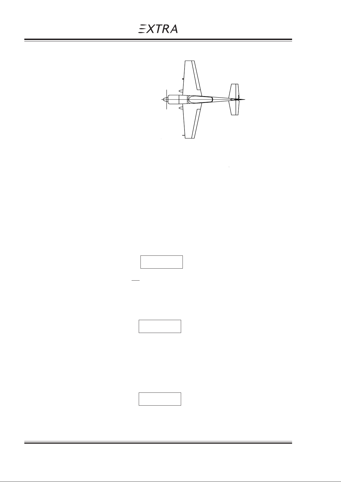
4.1.1 EXTERIOR INSPECTION ILLUSTRATION
4.1.2 GENERAL
Visually check airplane for general condition during walk around inspection. Perform exterior
check as outlined in the picture above in counterclockwise direction.
4.2 CHECKLIST PROCEDURES
1) Cockpit
1. Pilot's Operating Handbook (AVAILABLE)
2. Airplane weight and balance CHECKED
3. Ignition switch OFF
4. Master switch ON
5. Fuel quantity indicators CHECK
6. Master switch OFF
7. Fuel selector * "ACRO & CENTER"
3
4
2
1
5
NOTE *
Although safe operation did not require the use of the tanks in a specific sequence, it is
recommended to set fuel selector to "ACRO & CENTER" Tank position!
8. Pitot-Static-Drain CHECK FOR WATER
ACCUMULATIONS
NOTE
If water exists, drain by removing the plug. Reinstall plug.
9. "Acro & Center" Tank CHECK
FOR LEAKAGE
NOTE
Pay attention for fuel accumulations between alu-tank and GRP-cover. (This is indicated by
a blue color)
4 - 4 Page Date: 20. April 2002
Page 47

Pilot´s Operating Handbook
EXTRA 200
2) Empennage
1. All round inspection, canopy, surfaces,
stabilizer, elevator, trim rudder and tailwheel CHECK
2. Horizontal stabilizer attachment bolts CHECK FOR FREEPLAY BY
3) Right Wing
1. Aileron, freedom of movement and security CHECK
2. Trailing edge CHECK
3. Fuel tank vent opening (right landing gear) CHECK
4. Fuel quantity CHECK
5. Fuel tank filler cap CHECK
6. Right landing gear, wheel and brake CHECK
7. Stall warning vane CHECK
4) Nose
Normal Procedures
Section 4
MOVING THE TIP OF THE
HORIZ. STABILIZER UP- AND
DOWNWARDS
1. Engine oil dipstick CHECK
2. Propeller and spinner CHECK
3. Air inlet CHECK
4. Fuel quantity ("Acro & Center" tank) CHECK
5. Fuel tank filler cap CHECK
6. "Acro & Center" tank drain DRAIN FOR AT LEAST 4
SECONDS TO CLEAR SUMP OF
POSSIBLE WATER;
CHECK CLOSED
7. "Wing tank" drain DRAIN FOR AT LEAST 4
SECONDS TO CLEAR SUMP OF
POSSIBLE WATER;
CHECK CLOSED
8. Fuel filter drain DRAIN FOR AT LEAST 4
SECONDS TO CLEAR
FILTER OF POSSIBLE WATER;
CHECK CLOSED
5) Left wing
1. Left landing gear, wheel and brakes CHECK
2. Fuel quantity CHECK
3. Fuel tank filler cap CHECK
4. Pitot cover REMOVE
5. Trailing edge CHECK
6. Aileron, freedom of movement and security CHECK
Page Date: 20. April 2002 4 - 5
Page 48

Section 4
Normal Procedures
6) Before starting engine
1. Preflight inspection COMPLETE
2. Passenger briefing COMPLETE
3. Parachute handling briefing COMPLETE
4. Seats, seatbelts, shoulder harnesses ADJUST AND LOCK
5. Canopy CLOSE AND LOCK
6. Brake CHECK
7. Master switch ON
8. Avionics power switch OFF
9. Electrical equipment OFF
10. Alternator ON
11. Wingtip position / Strobe lights ON
4.3 STARTING PROCEDURES
Pilot´s Operating Handbook
EXTRA 200
4.3.1 COLD ENGINES
The following starting procedures are recommended, however, the starting conditions may
necessitate some variation from these procedures.
1. Perform preflight inspection.
2. Set propeller governor control to "High RPM" position.
3. Open throttle approximately 1/4 travel.
4. Turn boost pump "ON".
5. Move mixture control to "FULL RICH" until a slight but steady
fuel flow is noted (approximately 3 to 5 seconds) and return
mixture control to "IDLE CUT-OFF".
Turn boost pump "OFF".
6. Engage starter.
7. When engine fires release the ignition switch back to "BOTH".
8. Move mixture control slowly and smoothly to "FULL RICH".
9. Check the oil pressure gauge. If minimum oil pressure is not
indicated within 30 seconds, shut off the engine and determine trouble.
4 - 6 Page Date: 20. April 2002
Page 49

Pilot´s Operating Handbook
EXTRA 200
4.3.2 HOT ENGINES
Because of the fact that the fuel percolates and the system must be cleared of vapour, it is
recommended to use the same procedure as outlined for cold engine start.
4.4 TAXIING THE AIRCRAFT
1. Canopy CLOSE AND LOCK
2. Brake CHECK
3. Altimeter Set on QFE or QNH
4. Avionic master switch ON
5. Electrical equipment ON
6. Radio Set and test
7. Mixture Leave in "FULL RICH" position
Operate only with the propeller in minimum blade angle (High RPM).
Warm-up at approximately 1000-1200 RPM. The engine is ready for takeoff when the
throttle can be opened without the engine faltering.
Normal Procedures
Section 4
Scale error max. +60 ft.
4.5 TAKE-OFF PROCEDURE
4.5.1 BEFORE TAKE-OFF
Before you line up at the runway for takeoff:
- Check oil pressure and oil temperature.
- Check the magnetos at 1800 RPM. Allowed drop is 175 RPM
(max. difference 50 RPM).
- Check Alternator Output.
- Move also the propeller control through its complete range to check operation and
return to full "HIGH RPM" position.
Turn boost pump "ON" (check indicator movement on the fuel pressure gauge).
The RPM Gauge is electronically operated. To check the magnetos the RPM source switch
must be set to the same magneto as the ignition switch. Otherwise the gauge will show
zero.
NOTE
Note
4.5.2 TAKE-OFF
Set throttle smoothly to max and let the airspeed go up to 70-75 KIAS (130-139 km/h). A
light pressure on the stick lifts the tail to horizontal position. Rotate the aircraft at 75 KIAS
(139 km/h). On reaching climb speed of 100 KIAS (185 km/h) reduce the RPM to 2500 and
proceed climbing.
Page Date: 20. April 2002 4 - 7
Page Date: 14. July 2008
Page 50

Section 4
Normal Procedures
4.6 CLIMB
The maximum continuous RPM is restricted to 2500.
Turn boost pump "OFF".
4.7 CRUISE
1. Altitude - As selected
2. Throttle / RPM - Adjust for cruising speed
3. Mixture - Adjust for cruising speed
4. Trim - As required
5. Fuel - Check periodically
4.8 LANDING PROCEDURES
4.8.1 DESCENT
Pilot´s Operating Handbook
EXTRA 200
1. Throttle - Reduce
2. Mixture - "FULL RICH"
3. Trim -Adjust
4. Fuel selector valve* - "ACRO & CENTER" tank
Although safe operation did not require the use of the tanks in a specific sequence, it is
recommended to set fuel selector to "ACRO & CENTER" tank position!
4.8.2 APPROACH
1. Boost pump - ON
2. Mixture - Set to "RICH"
3. Airspeed - Reduce to approach speed
4. Propeller -Set to low pitch ("HIGH RPM")
It is recommended to reduce the RPM during approach and landing in order to avoid unnecessary noise.
In case of "Go Around", RPM control must be set to max. RPM before applying power.
NOTE
NOTE
4.8.3 BEFORE LANDING
1. Landing approach - Proceed
2. Airspeed on final - Maintain 75 KIAS (139 km/h)
3. Elevator trim - Adjust
4 - 8 Page Date: 20. April 2002
Page Date: 28. February 2006
Page 51

Pilot´s Operating Handbook
EXTRA 200
Stall speed will be
MTOW = 700 kg : 53 KIAS (98 km/h)
MTOW = 800 kg : 58 KIAS (107 km/h)
MTOW = 840 kg : 59 KIAS (109 km/h)
4.8.4 NORMAL LANDING
1. Landing - Perform as practicable
2. Touchdown - 3 point landing
The rudder is effective down to 30 KIAS (56 km/h) airspeed
Normal Procedures
Section 4
NOTE
with respect to surface
and weather condition
NOTE
3. Throttle - CLOSE / IDLE
4. Braking - Minimum required
4.9 GO-AROUND
Decide early in the approach if it is necessary to go around and
then start go-around before too low altitude and airspeed are
reached.
Proceed as follows:
1. RPM control - "HIGH RPM" / Full forward
2. Throttle - "OPEN" / TAKEOFF power
3. Airspeed - Minimum 90 KIAS (167 km/h)
4.10 SHUTDOWN
1. Boost pump - "OFF"
2. Engine - Run for 1 min. at 1000 RPM
3. Dead cut check - Perform
4. Avionic master switch - "OFF" (if installed)
5. Mixture - "IDLE CUT OFF"
6. Ignition switch - "OFF"
7. Master switch - "OFF"
Rotate to go-around attitude
4.11 LEAVING THE AIRCRAFT
1. Canopy - Close and lock
2. Aircraft - Secure
3. Pitot cover - Attach
4. Log book - Comply
Page Date: 20. April 2002 4 - 9
Page Date: 14. July 2008
Page 52

Section 4
Normal Procedures
4.12 ACROBATIC MANEUVERS
4.12.1 GENERAL
Prior to executing these maneuvers tighten harnesses and check all loose items are stowed.
Start the maneuvers at safe altitude and max continuous power setting if not otherwise
noted.
For maneuver limits refer to Section 2 LIMITATIONS.
After termination of acrobatic maneuvers the artificial horizon (if installed) must be reset if
possible.
At high negative g-loads and zero g-periods it is normal that oil pressure and RPM indication
might drop down momentarily returning to normal status at positive g-loads.
N O T E
NOTE
Pilot´s Operating Handbook
EXTRA 200
The high permissible load factors of the airplane may exceed the individual physiological limits
of pilot or passenger. This fact must be considered when pulling or pushing high g's.
4.12.2 MANEUVERS
Particular caution must be exercised when performing maneuvers at speeds above V
[154 KIAS (285 km/h)]. Large or abrupt control inputs above this speed may impose
unacceptably high loads which exceed the structural capability of the aircraft.
Acrobatics is traditionally understood as maneuvers like loop, humpty bump, hammerhead
turn, aileron roll etc..
This manual does not undertake to teach acrobatics, however, it is meant to demonstrate
the plane's capabilities.
WARNING
CAUTION
A
For this reason maneuvers are divided into segments. The segments are described. Limitations are pointed out.
- Segment horizontal line:
A horizontal line may be flown with any speed between VS and V
4 - 10 Page Date: 20. April 2002
NE.
Page Date: 14. July 2008
Page 53

Pilot´s Operating Handbook
EXTRA 200
- - Segment "line 45° climbing":
The plane will follow the line at max. power. The speed will not decrease below 80 KIAS
(148 km/h).
- Segment "line 90° up":
Any entry speed may be used. Out of a horizontal pull-up at 200 KIAS (370 km/h) the
vertical penetration will be 2.500 ft. The speed will gradually decrease to 0.
In extremely long "line 90° up" an RPM decay may occur. This is related to a loss of oil
pressure. Positive g´s should be pulled immediately in order to protect the engine. Oil
pressure will return immediately.
- Segment "line 45° diving":
Throttle must be reduced in order to avoid exceeding VNE.
Normal Procedures
Section 4
NOTE
- Segment "line 90° diving":
Throttle must be reduced to idle in order to avoid exceeding VNE.
Above segments may be filled up with aileron rolls on snap rolls. Watch VA = 154 KIAS
(285 km/h) for aileron rolls with max. deflection.
Snap rolls should not be performed at speeds above 138 KIAS (256 km/h).
- Segment "1/4 loop, climbing":
The minimum recommended speed is 100 KIAS (185 km/h). If the maneuver is to be
followed by a vertical line, a higher entry speed is required depending on the expected
length of the line. A complete loop can be performed at speeds above 100 KIAS
(185 km/h).
NOTE
Since the maximum horizontal speed is 185 KIAS (343 km/h), higher speeds should be
avoided in acrobatics since an unnecessary loss of altitude would occur.
- Torque maneuvers:
All maneuvers with high angular velocity associated with high propeller RPM must be
considered dangerous for the engine crankshaft.
Although wooden composite propeller blades are used, the gyroscopic forces at the prop
flange are extremely high.
Page Date: 20. April 2002 4 - 11
Page Date: 14. July 2008
Page 54

Section 4
Normal Procedures
4.12.3 SPIN
Pilot´s Operating Handbook
EXTRA 200
CAUTION
If performing a gyroscopic maneuver such as flat spin, power on, or knife edge spin, reduce
RPM to 2400 in order to minimize the gyroscopic forces.
To enter a spin proceed as follows:
- Reduce speed, power idle
- When the plane stalls:
- Kick rudder to desired spin direction
- Hold ailerons neutral
- Stick back (positive spinning), Stick forward (negative spinning)
The plane will immediately enter a stable spin.
- Ailerons against spin direction will make the spin flatter.
- Ailerons into spin direction will lead to a spiral dive.
Above apply for positive and negative spinning.
To stop the spin:
- Apply opposite rudder
- Make sure, power idle
- Hold ailerons neutral
- Stick to neutral position
The plane will recover within 1/2 turn.
Recovery can still be improved by feeding in in-spin ailerons.
NOTE
If ever disorientation should occur during spins (normal or inverted) one method always
works to stop the spin:
- Power idle
- Kick rudder to the heavier side
(this will always be against spin direction)
- Take hands off the stick
The spin will end after 1/2 turn. The plane will be in a steep dive in a side-slip.
Recovery to normal flight can be performed easily.
NOTE
After six turns of spinning the altitude loss including recovery is 2800 ft.
4 - 12 Page Date: 20. April 2002
Page 55

Pilot´s Operating Handbook
EXTRA 200
Section 5
Performance
SECTION 5
PERFORMANCE
Table Of Contents
Paragraph Page
SECTION 5 PERFORMANCE
5.1 GENERAL ........................................................................................................................... 5-3
5.1.1 Performance Charts ............................................................................................................ 5-3
5.1.2 Definitions Of Terms............................................................................................................ 5-3
5.1.3 Sample Problem.................................................................................................................. 5-4
5.2 ISA CONVERSION.............................................................................................................. 5-5
5.3 AIRSPEED CALIBRA TION ................................................................................................. 5-6
5.4 STALL SPEED .................................................................................................................... 5-7
5.5 TAKEOFF PERFORMANCE............................................................................................... 5-8
5.6 RA TE OF CLIMB PERFORMANCE.................................................................................... 5-9
5.7 TIME, FUEL AND DISTANCE TO CLIMB ....................................................................... 5-10
5.8 TIME, FUEL AND DIST ANCE TO DESCEND................................................................... 5-11
5.9 CRUISING SPEED............................................................................................................ 5-12
5.10 ENDURANCE ................................................................................................................... 5-13
5.11 RANGE ............................................................................................................................. 5-14
5.12 CRUISE PERFORMANCE ................................................................................................ 5-15
5.13 LANDING DISTANCE ....................................................................................................... 5-16
Page Date: 20. April 2002 5 - 1
Page 56

Section 5
Performance
Pilot´s Operating Handbook
EXTRA 200
Left blank intentionally
5 - 2 Page Date: 20. April 2002
Page 57

Pilot´s Operating Handbook
EXTRA 200
5.1 GENERAL
Performance data charts on the following pages are presented to facilitate the planning of
flights in detail and with reasonable accuracy under various conditions. The data in the
charts have been computed from actual flight tests with the aircraft and engine in good
condition and using average piloting techniques.
It should be noted that the performance information presented in the range and endurance
charts allow for 45 minutes reserve fuel at specified speeds. Some indeterminate variables
such as engine and propeller, air turbulence and others may account for variations as high
as 10% or more in range and endurance. Therefore, it is important to utilize all available
information to estimate the fuel required for the particular flight.
5.1.1 PERFORMANCE CHARTS
Section 5
Performance
SECTION 5
PERFORMANCE
Performance data are presented in tabular or graphical form to illustrate the effect of different variables. Sufficiently detailed information are provided in the tables so that conservative
values can be selected and used to determine the particular performance figure with reasonable accuracy.
All speeds in this chapter are Indicated Air Speeds (IAS). The performance figures below
are given under following conditions.
1. Maximum allowed weight 840 kg (1852 lbs) except otherwise stated
2. Takeoff and landing on concrete surface.
3. No wind.
4. Standard atmospheric condition.
5.1.2 DEFINITIONS OF TERMS
For definition of terms, abbreviations and symbols refer to section 1, General.
Page Date: 20. April 2002 5 - 3
Page 58

Section 5
Performance
5.1.3 SAMPLE PROBLEM
CONDITIONS
Airfield Pressure Altitude:1500 ft (457 m), Outside air temperature on ground: 20°C
Cruising flight in FL 80 [8000 ft (2438 m)], Outside air temperature in FL 80: 10°C
TAKEOFF
The takeoff distance with T/O weight of 840kg (1852 lbs) is shown by Fig. 5.5
Result: Ground Roll: 257 m
Total Distance to clear a 50 ft (15 m) obstacle: 407 m
RATE OF CLIMB
The rate of climb in FL 80 (2438 m) with an aircraft weight of 750 kg is shown by Fig. 5.6
Result: Rate of climb: 950 ft/min
TIME, FUEL AND DISTANCE TO CLIMB
The values from airfield level 1500 ft (457 m) to FL 80 (2438 m) with an aircraft weight of 800 kg
is shown by Fig. 5.7:
Result: Time: (8.7 - 1.9) min = 6.8 min
Distance: (13 - 2.8) NM = 10.2 NM
Fuel consumption: (8.3 - 1.9) liters = 6.4 liters
Pilot´s Operating Handbook
EXTRA 200
CRUISING SPEED
The cruising speed in FL 80 (2438 m) with an aircraft weight of 840 kg and power setting of
65% is shown by Fig. 5.9.
Result: Cruising speed : 148 KTAS (274 km/h)
Cruise Altitude and Power Setting should be determined for most economical fuel
consumption and several other considerations.
FUEL CONSUMPTION
The fuel consumption in FL 80 (2438 m) with an aircraft weight of 840 kg and power setting of
65% is shown by Tab. 5.12.
Result: Fuel consumption: 34 liters per hour
RANGE
The range in FL 80 (2438 m) with an aircraft weight of 840 kg (1852 lbs) and power setting of
65%, is shown by Tab. 5.12, including fuel for warm up and takeoff from SL, max continuous
Power climb to cruising altitude, and a reserve of 19 liters (5 US Gal.) for 45 minutes with
45% Power. 5 liters (1.3 US Gal.) unusable fuel is taken into account.
Total fuel: 122 L (32 US Gal.)
Warm up & T/O: -4 L (-1.05 US Gal.)
Reserve: -19 L (-5 US Gal.)
Unusable fuel: -5 L (-1.3 US Gal.)
Usable fuel: 94 L (24 US Gal.)
Result: Range: 386 NM (714 km)
Endurance
The endurance in FL 80 (2438 m) is shown by Tab. 5.10.
Result: Endurance: 2.66 hours
5 - 4 Page Date: 20. April 2002
Page Date: 14. July 2008
Page 59
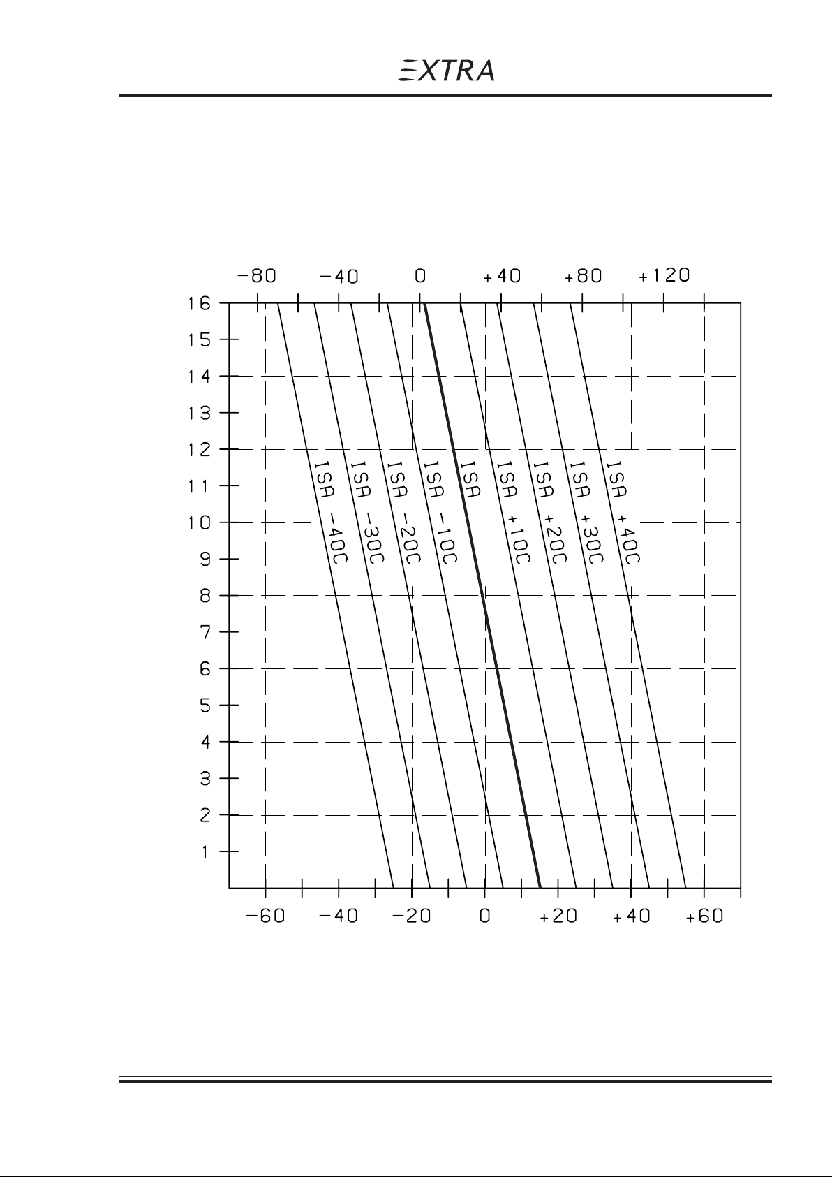
Pilot´s Operating Handbook
EXTRA 200
5.2 ISA CONVERSION
ISA Conversion of pressure altitude and outside air temperature
Section 5
Performance
Outside air temperature "OAT" ( °F )
Pressure altitude (ft x 1000)
Outside air temperature "OAT" ( °C )
Page Date: 20. April 2002 5 - 5
Page 60
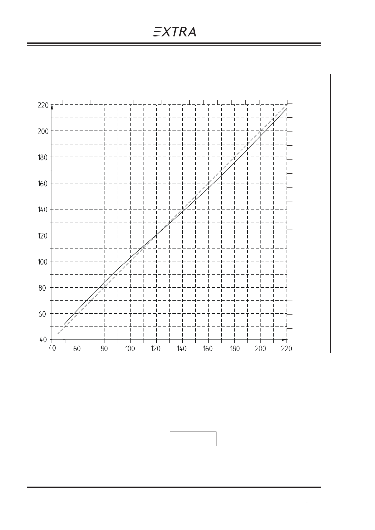
Section 5
)
Performance
5.3 AIRSPEED CALIBRATION
90 11 0 130 150 170 190 210 230 250 270 290 310 330 350 370 390 410
Pilot´s Operating Handbook
EXTRA 200
CAS (km/h
410
390
370
350
330
310
290
270
KIAS
KCAS
250
230
210
190
170
150
130
110
90
IAS (km/h)
NOTE
Indicated airspeed assumes zero instrument error
5 - 6 Page Date: 20. April 2002
Page Date: 14. July 2008
Page 61
Pilot´s Operating Handbook
EXTRA 200
5.4 STALL SPEED
Condition:
Power Idle
Forward C.G. position
ANGLE OF BANK
WEIGHT CATEGORY 0° 30° 45° 60°
KIAS KCAS KIAS KCAS KIAS KCAS KIAS KCAS
(km/h) (km/h) (km/h) (km/h) (km/h) (km/h) (km/h) (km/h)
Section 5
Performance
840 kg NORMAL 59 56 64 60 72 67 82 79
(1852 lbs) (109) (104) (119) (111) (133) (124) (152) (146)
800 kg ACRO 58 55 63 59 70 65 81 78
(1763 lbs) (2 seat) (107) (102) (117) (109) (130) (120) (150) (144)
700 kg ACRO 53 51 58 55 65 61 75 72
(1543 lbs) (1 seat) (98) (94) (107) (102) (120) (113) (139) (133)
Max. altitude loss during stall recovery is approximately 100 ft (30 m).
Page Date: 20. April 2002 5 - 7
Page Date: 14. July 2008
Page 62
Section 5
Performance
Pilot´s Operating Handbook
5.5 TAKEOFF PERFORMANCE
Power: 2700 RPM and full throttle before brake release
Landing runway: paved level dry runway
For every 5 kts (9 km/h) headwind, the takeoff (T/O) distance can be decreased by 5%. For
every 2 kts (4 km/h) tailwind [up to 10 kts (19 km/h)], the (T/O) distance is increased by
10%. On a solid, dry and plain Grass Runway, the T/O distance is increased by 15%.
Weight: 700 kg (1543 lbs) Liftoff speed (T/O): 70 KIAS (130 km/h)
Takeoff distance in meter Obstacle clearance speed over 15m (50ft) : 75 KIAS (139 km/h)
-20°C OAT -10°C 0°C 10°C 20°C 30°C 40°C
EXTRA 200
PA
T/O 50 ft T/O 50 ft T/O 50 ft T/O 50 ft T/O 50 ft T/O 50 ft T/O 50 ft
Sea level 116 183 129 205 144 228 160 253 177 280 195 309 214 340
2000 135 213 151 239 168 266 186 295 206 327 227 360 250 396
4000 157 249 176 279 196 311 218 345 241 382 266 422 293 464
6000 184 292 206 327 230 364 255 405 283 448 312 495 344 545
8000 216 343 242 384 270 429 301 476 333 528 368 583 405 642
Takeoff distance in ft
-20°C OAT -10°C 0°C 10°C 20°C 30°C 40°C
PA
T/O 50 ft T/O 50 ft T/O 50 ft T/O 50 ft T/O 50 ft T/O 50 ft T/O 50 ft
Sea level 381 600 423 673 472 748 525 830 581 919 640 1014 702 1115
2000 443 699 495 784 551 873 610 968 676 1073 745 1181 820 1299
4000 515 817 577 915 643 1020 715 1132 791 1253 873 1385 961 1522
6000 604 958 676 1073 755 1194 837 1329 928 1470 1024 1624 1129 1788
8000 709 1125 794 1260 886 1407 988 1562 1093 1732 1207 1913 1329 2106
Weight: 840 kg (1852 lbs) Liftoff speed (T/O): 73 KIAS (135 km/h)
Takeoff distance in meter Obstacle clearance speed over 15m (50ft) : 78 KIAS (144 km/h)
-20°C OAT -10°C 0°C 10°C 20°C 30°C 40°C
PA
T/O 50 ft T/O 50 ft T/O 50 ft T/O 50 ft T/O 50 ft T/O 50 ft T/O 50 ft
Sea level 149 236 167 264 186 295 206 327 228 362 252 399 277 438
2000 174 275 194 308 217 343 240 381 266 422 293 465 323 512
4000 203 321 227 360 253 401 281 446 311 493 343 544 378 599
6000 238 377 238 422 297 470 330 523 365 579 403 639 444 703
8000 279 442 313 496 349 553 388 615 430 681 475 752 523 828
Takeoff distance in ft
-20°C OAT -10°C 0°C 10°C 20°C 30°C 40°C
PA
roll 50 ft roll 50 ft roll 50 ft roll 50 ft roll 50 ft roll 50 ft roll 50 ft
Sea level 489 774 548 866 610 968 676 1073 748 1188 827 1309 909 1437
2000 571 902 636 1010 712 1125 787 1250 873 1385 961 1526 1060 1680
4000 666 1053 745 1181 830 1316 922 1463 1020 1617 1125 1785 1240 1965
6000 781 1237 781 1385 974 1542 1083 1716 1198 1900 1322 2096 1457 2306
8000 915 1450 1027 1627 1145 1814 1273 2018 1411 2234 1558 2467 1716 2717
5 - 8 Page Date: 20. April 2002
Page Date: 14. July 2008
Page 63
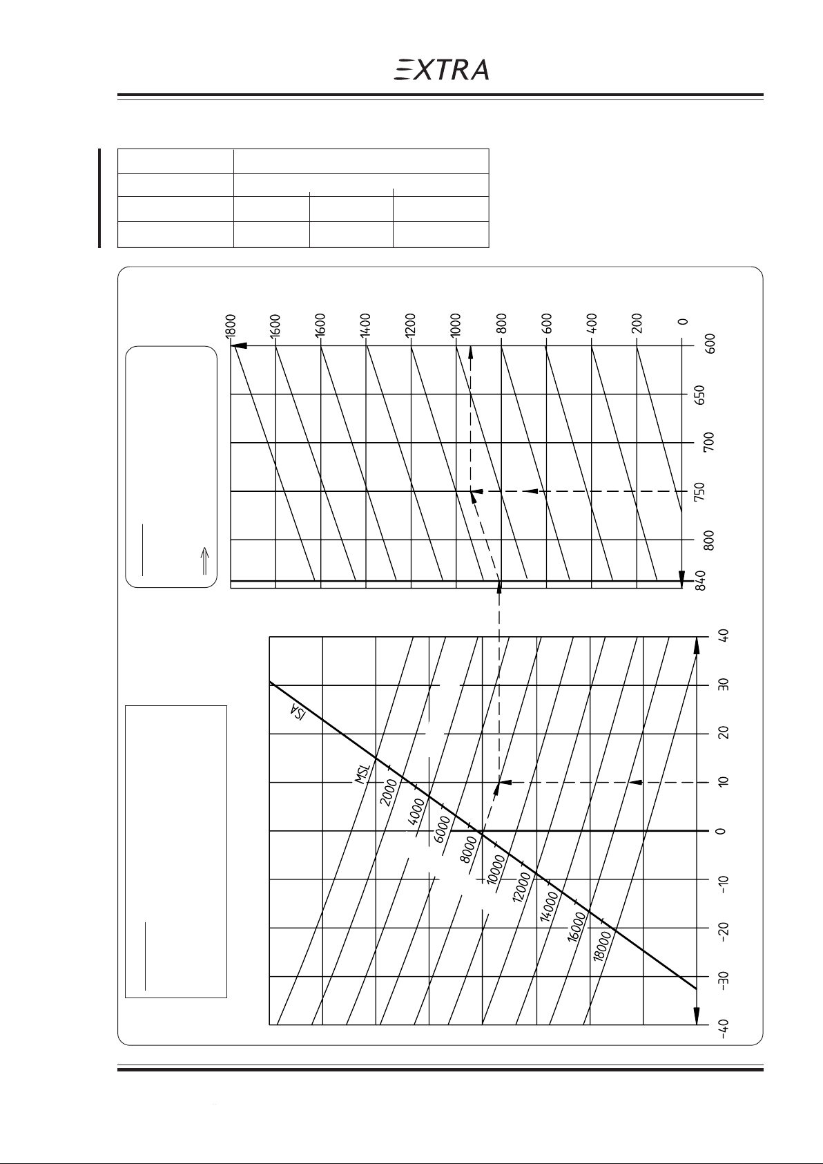
Pilot´s Operating Handbook
EXTRA 200
5.6 RATE OF CLIMB PERFORMANCE
Weight Airspeed during climb KIAS (km/h)
sea level 5000 ft 12000 ft
840 Kg (1852 lbs) 86 (159) 84 (156) 82 (152)
700 Kg (1543 lbs) 84 (156) 82 (152) 80 (148)
climb rate (ft/min)
Section 5
Performance
Example:
Pressure altitude: 8000 ft
Outside air temperature: +10°c
Weight: 750 kg (1653 lbs)
Climb rate: 950 ft/min
above 8000 ft f. best Power
Weight in Kg (lbs)
(1852) (1763) (1653) (1543) (1432) (1322)
density altitude (ft)
Pres. altitude (ft)
Outside air temperature (°c)
Conditions:
Power: Max. Continuous Power
Revolution: 2500 RPM
Mixture: below 8000 ft rich
Page Date: 20. April 2002 5 - 9
Page Date: 14. July 2008
Page 64
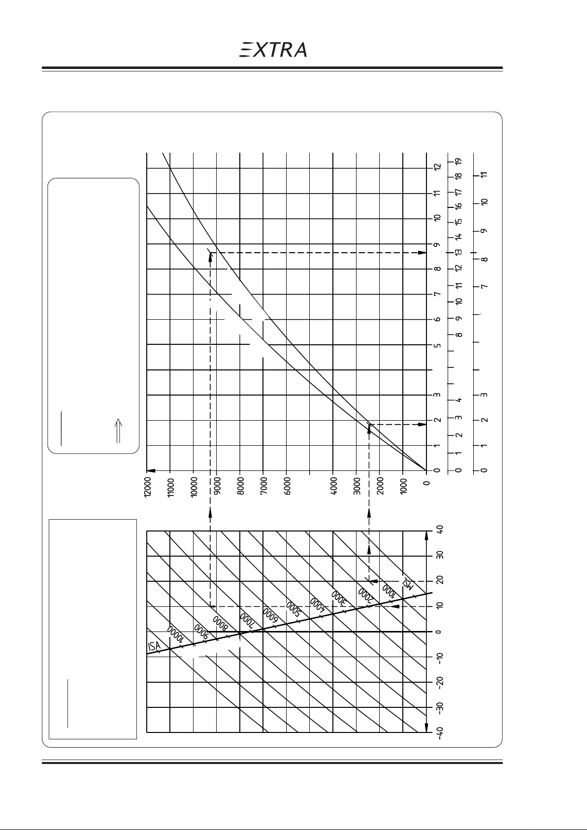
Section 5
Performance
5.7 TIME, FUEL AND DISTANCE TO CLIMB
Pilot´s Operating Handbook
EXTRA 200
840 kg (1852 lbs)
Climb time: 8,7-1,9= 6,8 min
Distance: 13 -2,8=10,2 NM
Fuel consumption: 8,3-1,9= 6,4 liters (1.6 US. Gal.)
Example
Weight: 800 kg (1764 lbs)
Airfield pres. altitude: 1500 ft Cruise pres. altitude: 8000 ft
Airfield temperature: +20°c Outside air temperature +10°c
T/O weight 700Kg (1543lbs)
Density
altitude (ft)
Time (min)
Distance(NM)
Fuel in liter ((US Gal.)
0 (0.52) (1.05) (1.58) (2.11) (2.63) (3.16)
above 8000 ft: for best power
Press. Altitude
Outside air temperature (°c)
Conditions:
No Wind, Speed for best climb
Power: Max. continuous power
Revolution: 2500 RPM
Mixture: below 8000 ft: rich
5 - 10 Page Date: 20. April 2002
Page 65
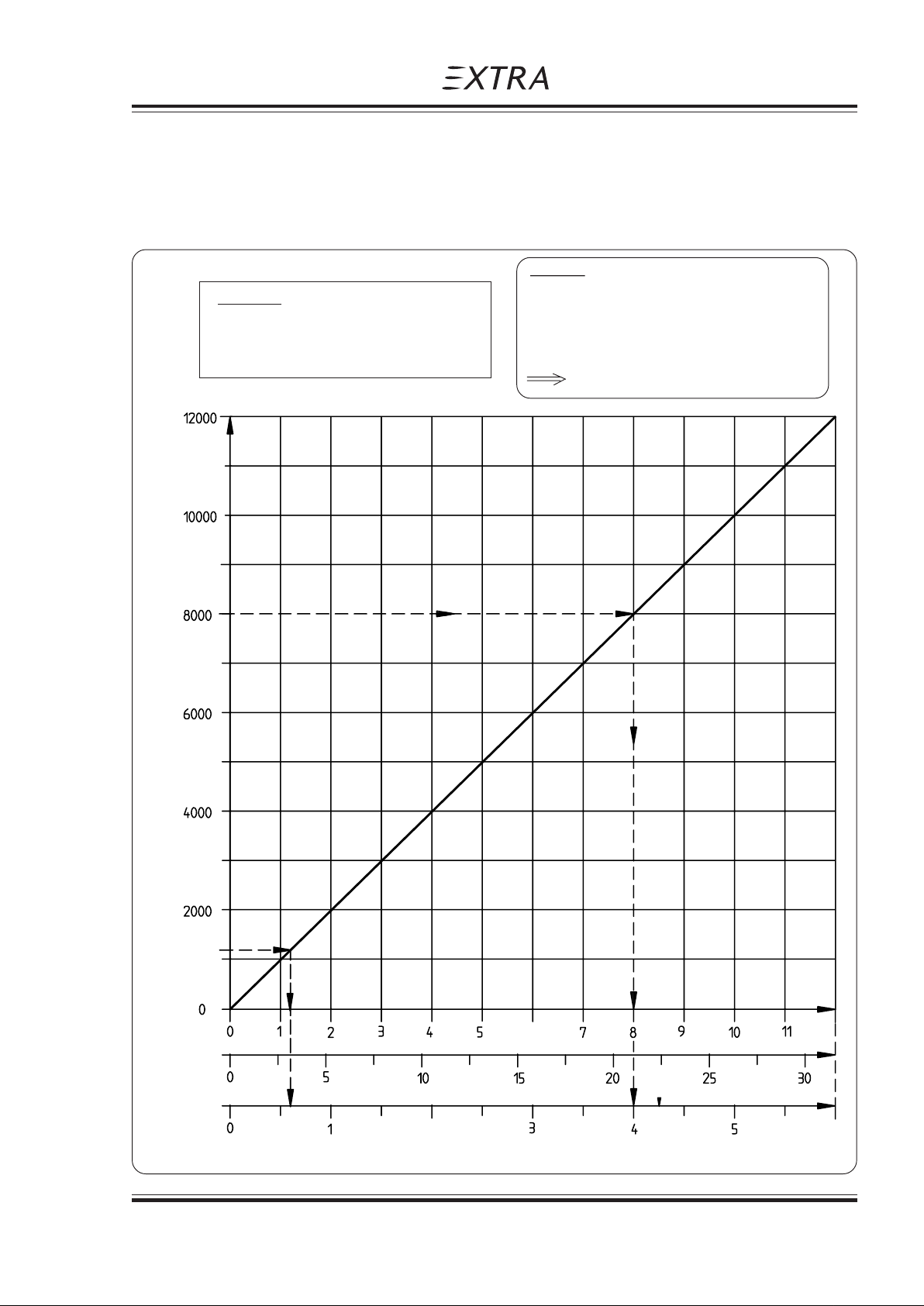
Pilot´s Operating Handbook
EXTRA 200
5.8 TIME, FUEL AND DISTANCE TO DESCEND
During the descent adjust the engine power for V = 150 KIAS and a rate of descent of
1000ft/min. Furthermore the engine temperature has to be kept in the green range.
The diagramm below may be used for all A/C masses and temperatures.
Condition:
No Wind,
Manifold pres. as required, ca. 12 inHg
Revolution: 2500 RPM
Section 5
Performance
Example
Airfield pres. altitude: 1200 ft
Cruise pres. altitude: 8000 ft
Time to descend 8.0 - 1,2 = 7,8 min
Distance: 21 - 3 = 18 NM
Fuel consumption: 4,0 - 0,6 = 3,4 Liter
Pres. altitude (ft)
0 (0.26) (0.52) (0.78) (1.05) (1.3)
Time
(min)
Distance
(NM)
Fuel in liter (US Gal.)
Page Date: 20. April 2002 5 - 11
Page 66
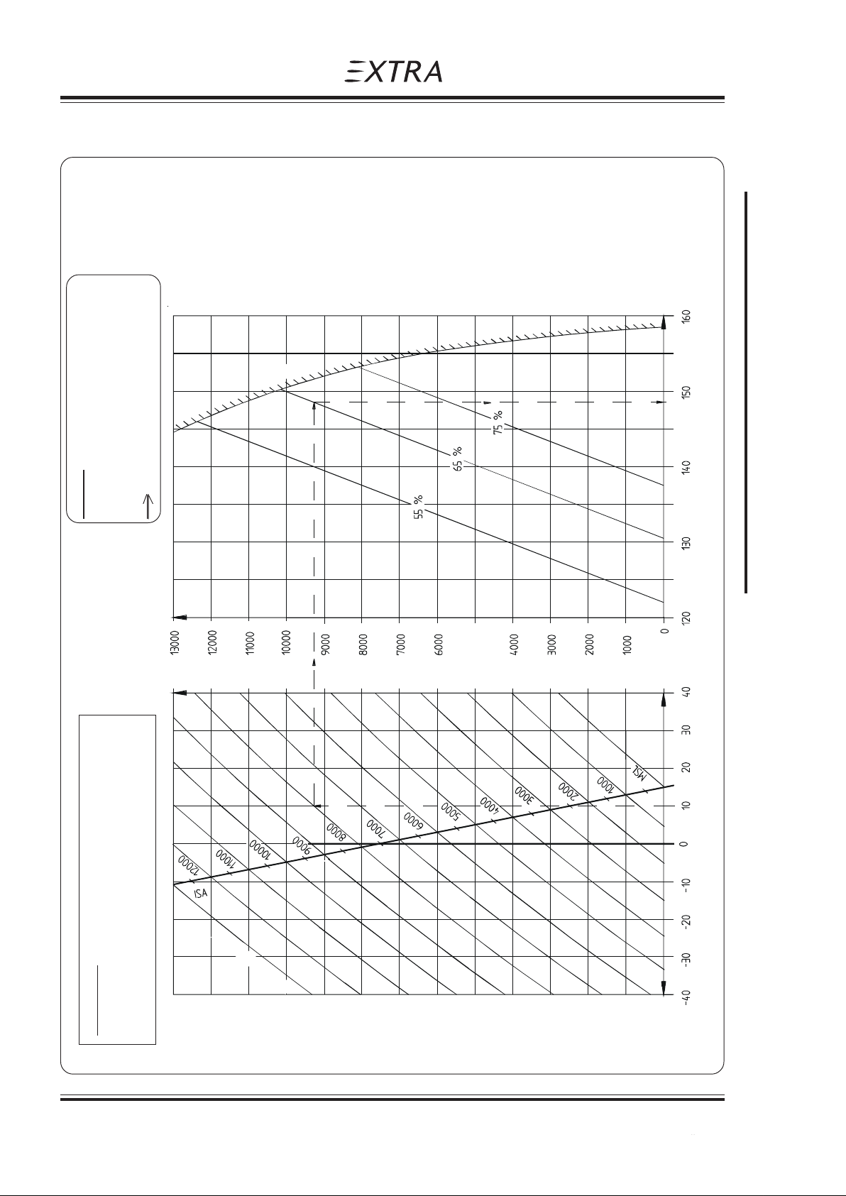
Section 5
Performance
5.9 CRUISING SPEED
Pilot´s Operating Handbook
e
l
t
t
o
r
h
t
l
l
u
f
EXTRA 200
Example
Cruise pres. altitude: 8000 ft
Outside air temperature +10°c
Power: 65%
Cruising Speed: 148 KTAS (274 km/h)
for best economy below 75%
Cruise Speed KTAS (km/h)
(ft)
Altitude
Densitiy
(222) (241) (259 ) (278) (29 6)
Outside Air T emperature °C
e
d
u
t
i
t
l
a
e
r
u
s
s
e
r
p
Conditions:
Weight: 840 Kg (1852 lbs)
Mixture: for best power at 75%, and
5 - 12 Page Date: 20. April 2002
Page Date: 14. July 2008
Page 67
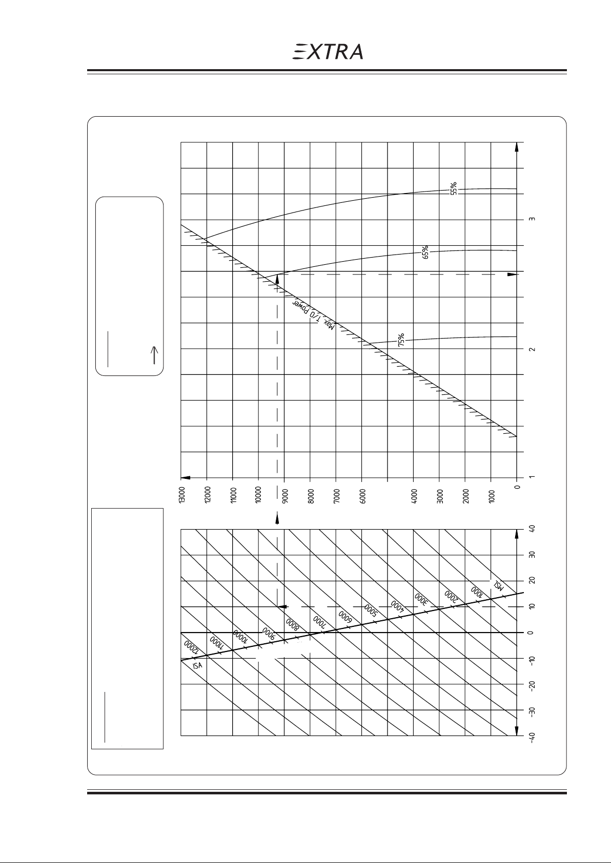
Pilot´s Operating Handbook
EXTRA 200
5.10 ENDURANCE
Section 5
Performance
Endurance (h)
Example
Cruise pres. altitude: 8000 ft
Outside air temperature +10°c
Power: 65%, 2350 RPM, 21.5 in Hg
Endurance: 2.66 h
Press. Altitude
Density
altitude (ft)
Conditions:
Weight: 840 Kg (1852 lbs), total fuel:117 liter (30.8
US Gal.), less 4 liter (1.05 US Gal.) for warm up and
taxi, less 19 liter (5 US Gal.) for a flightreserve of 45
min at 45% power.
Page Date: 20. April 2002 5 - 13
Outside air temperature (°c)
Page 68
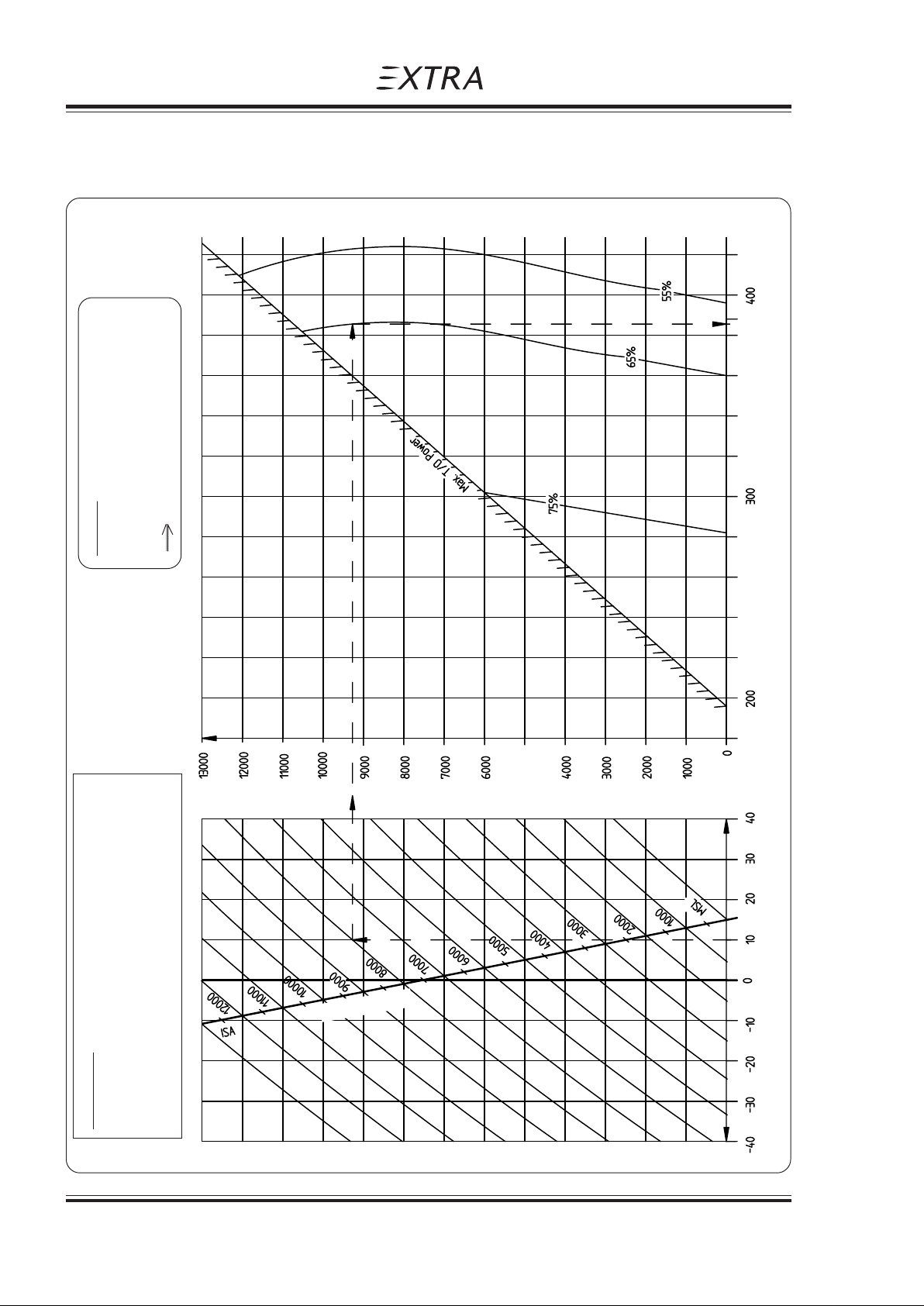
Section 5
Performance
5.11 RANGE
Pilot´s Operating Handbook
EXTRA 200
Range (NM)
Example
Cruise pres. altitude: 8000 ft
Outside air temperature +10°c
Power: 65%, 2350 RPM, 21.5 in Hg
Range: 386 NM
Density
altitude (ft)
Press. Altitude
Outside air altitude (°c)
Conditions:
Weight: 840 Kg (1852 lbs), total fuel:117 liter (30.8
US Gal.), less 4 liter (1.05 US Gal.) for warm up and
taxi, less 19 liter (5 US Gal.) for a flightreserve of 45
min at 45% power.
5 - 14 Page Date: 20. April 2002
Page 69
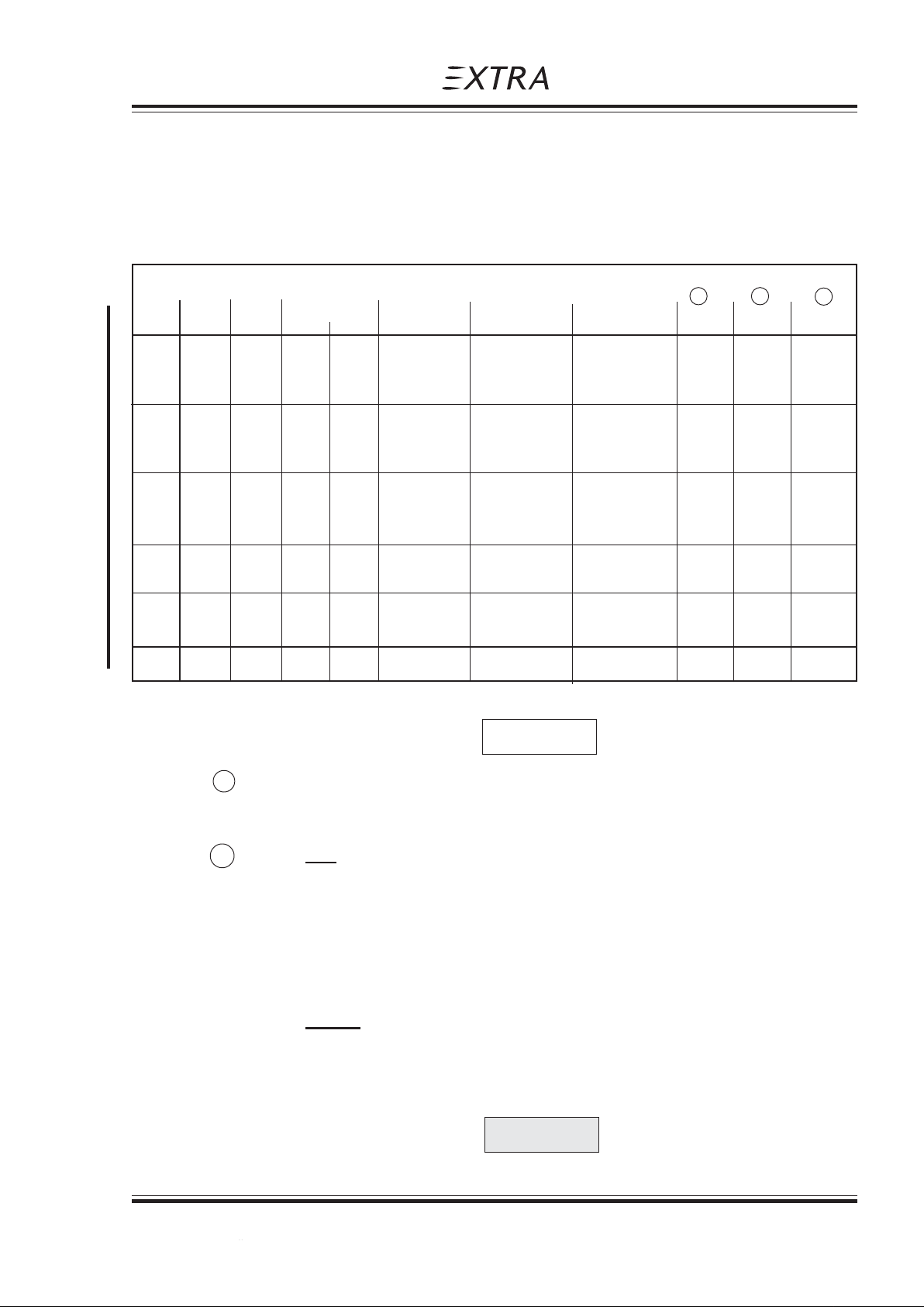
Pilot´s Operating Handbook
EXTRA 200
Section 5
Performance
5.12 CRUISE PERFORMANCE
Range and Endurance values for a T/O weight of 840 kg (1852 lbs) including fuel for warmup and takeoff from SL, max. cont. Power climb to cruising altitude, and a reserve of 19
liters (5 US Gal.) for 45 minutes with 45% power. 5 liters (1.3 US Gal.) unusable fuel is taken
into account. (At ISA - Conditions.)
PA Eng. Manif. Power Setting Fuel TAS IAS Endur. Range Mixture
Press. Consumption 1 1 2
[ft] [RPM] [IN HG] [%] [Hp] [l/h] (gal/h) [Kts] (km/h) [Kts] (km/h) [h] [NM] Best ...
2000 2400 25,0 75 150 46 (12,2) 141 (261) 135 (250) 2,05 288 Power
2300 23,5 65 130 34 (9,0) 134 (248) 128 (237) 2.75 368 Economy
2000 23,5 55 110 29 (7,7) 126 (233) 122 (226) 3.21 405 Economy
4000 2400 24,5 75 150 46 (12,2) 145 (269) 135 (250) 2,05 294 Power
2200 23,8 65 130 34 (9,0) 138 (256) 128 (237) 2.73 374 Economy
2000 23,1 55 110 29 (7,7) 130 (241) 123 (228) 3.18 412 Economy
6000 2500 23,1 75 150 46 (12,2) 150 (278) 135 (250) 2.05 303 Economy
2200 23,0 65 130 34 (9,0) 142 (263) 128 (237) 2,71 382 Economy
2000 22,8 55 110 29 (7,7) 134 (248) 123 (228) 3.15 421 Economy
8000 2350 21,5 65 130 34 (9,0) 146 (270) 128 (237) 2.70 389 Economy
2050 21,5 55 110 29 (7,7) 138 (256) 122 (226) 3,12 428 Economy
10000 2500 19,9 65 130 35 (9,2) 150 (278) 128 (237) 2.60 380 Economy
2200 20,0 55 110 30 (7,9) 142 (263) 121 (224) 2.98 416 Economy
12000 2300 18,3 55 110 31 (8,2) 146 (270) 122 (226) 2.85 408 Economy
NOTE
1 For temperatures above/ below Standard (ISA), increase/decrease Range 1,7% and
Endurance 1,1% for each 10°C above/below Standard Day Temperature for particular
altitude.
2 Leaning with exhaust gas temperature (EGT) gage
For the adjustment "Best Power", first lean the mixture to achieve the top exhaust
temperature (peak EGT) and then enrich again until the exhaust temperature is 100°F
lower than peak EGT.
For the adjustment "Best Economy", simply lean the mixture to achieve the top
exhaust temperature (peak EGT).
Leaning without exhaust gas temperature (EGT) gage and flowmeter
Slowly move mixture control from "Full rich" position towards lean position. Continue
leaning until slight loss of power is noted (Loss of power may or may not be accompanied
by rough engine run). Then enrich until engine runs smoothly and power is regained.
CAUTION
Always return the mixture to full rich before increasing power settings.
Page Date: 20. April 2002 5 - 15
Page Date: 14. July 2008
Page 70
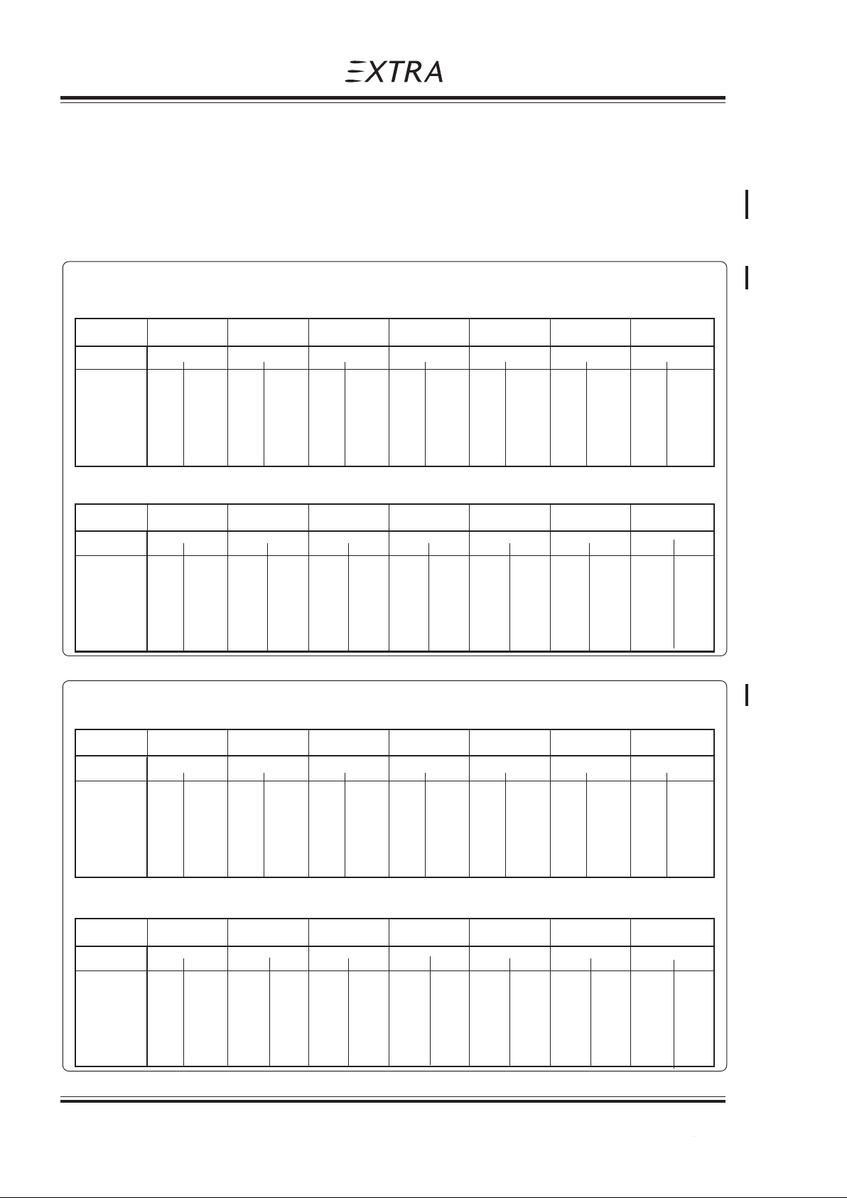
Section 5
Performance
Pilot´s Operating Handbook
5.13 LANDING DISTANCE
Power: Idle and propeller of full fine
Landing runway: Paved level dry runway
For every 5 kts (9 km/h) headwind, the landing distance (L/D) can be decreased by 10%.
For every 2 kts (4 km/h) Tailwind [up to 10 kts (19 km/h)], the landing distance (L/D) is
increased by 10%. On a solid, dry and plain Grass Runway, the landing distance (L/D) is
increased by 15%.
Weight: 700 kg (1543 lbs) Landing speed at 15m (50ft) : 70 KIAS (130 km/h)
Landing distance in meter Side slip from 15m (50 ft) down to ca.5 m (15ft)
-20°C OAT -10°C 0°C 10°C 20°C 30°C 40°C
PA
L/D 50 ft L/D 50 ft L/D 50 ft L/D 50 ft L/D 50 ft L/D 50 ft L/D 50 ft
Sea level 150 341 164 371 178 403 192 436 208 471 223 507 240 544
2000 166 377 181 411 197 446 213 483 230 521 247 561 266 603
4000 185 418 201 456 218 495 236 535 255 578 274 622 295 668
6000 205 465 223 506 242 549 262 595 283 642 305 691 327 742
8000 228 517 248 563 269 611 292 661 315 714 339 768 364 825
EXTRA 200
Landing distance in ft
-20°C OAT -10°C 0°C 10°C 20°C 30°C 40°C
PA
L/D 50 ft L/D 50 ft L/D 50 ft L/D 50 ft L/D 50 ft L/D 50 ft L/D 50 ft
Sea level 492 1119 538 1217 584 1322 630 1430 682 1545 732 1663 787 1785
2000 545 1237 594 1348 646 1463 699 1585 755 1709 810 1841 873 1978
4000 607 1371 659 1496 715 1624 774 1755 837 1896 899 2041 968 2192
6000 673 1526 732 1660 794 1801 860 1952 928 2106 1001 2267 1073 2434
8000 748 1696 814 1847 883 2005 958 2169 1033 2343 1112 2520 1194 2707
Weight: 840 kg (1852 lbs) Landing speed at 15m (50ft) : 73 KIAS (135 km/h)
Landing distance in meter Side slip from 15m (50 ft) down to ca.5 m (15ft)
-20°C OAT -10°C 0°C 10°C 20°C 30°C 40°C
PA
L/D 50 ft L/D 50 ft L/D 50 ft L/D 50 ft L/D 50 ft L/D 50 ft L/D 50 ft
Sea level 194 440 211 479 229 520 248 563 268 608 288 654 310 703
2000 215 487 234 531 254 576 275 623 297 673 319 724 343 778
4000 238 540 259 588 282 639 305 691 329 746 354 803 380 863
6000 265 600 288 653 313 709 338 767 365 828 393 892 422 958
8000 294 667 320 727 348 789 376 854 406 921 437 992 470 1065
Landing distance in ft
-20°C OAT -10°C 0°C 10°C 20°C 30°C 40°C
PA
L/D 50 ft L/D 50 ft L/D 50 ft L/D 50 ft L/D 50 ft L/D 50 ft L/D 50 ft
Sea level 636 1444 692 1572 751 1706 814 1847 879 1995 945 2146 1017 2306
2000 705 1598 768 1742 833 1890 902 2044 974 2208 1047 2375 1125 2552
4000 781 1772 850 1929 925 2096 1001 2267 1079 2448 1161 2635 1247 2831
6000 869 1969 945 2142 1027 2326 1109 2516 1198 2717 1289 2927 1385 3143
8000 965 2188 1050 2385 1142 2589 1234 2802 1332 3022 1434 3255 1542 3494
5 - 16 Page Date: 20. April 2002
Page Date: 14. July 2008
Page 71

Pilot´s Operating Handbook
EXTRA 200
Weight and Balance and Equipment List
Section 6
SECTION 6
WEIGHT AND BALANCE AND EQUIPMENT LIST
Table of Contents
Paragraph Page
SECTION 6 WEIGHT AND BALANCE AND EQUIPMENT LIST
6.1 GENERAL ........................................................................................................................... 6-3
6.2 AIRCRAFT WEIGHING PROCEDURE ............................................................................... 6-3
6.2.1 Owners Weight And Balance Record .................................................................................. 6-4
6.3 CENTER OF GRA VITY CALCULATION (SAMPLE PROBLEM) ........................................ 6-5
6.3.1 Sample................................................................................................................................6-7
6.3.2 Weight And Balance Record Sheet ..................................................................................... 6-7
6.4 LOADING WEIGHTS AND MOMENTS .............................................................................. 6-8
6.5 WEIGHTS AND MOMENTS LIMITS ................................................................................... 6-9
6.6 EQUIPMENT LIST ............................................................................................................ 6-10
Page Date: 20. April 2002 6 - 1
Page 72

Section 6
Weight and Balance and Equipment List
Pilot´s Operating Handbook
EXTRA 200
Left blank intentionally
6 - 2 Page Date: 20. April 2002
Page 73
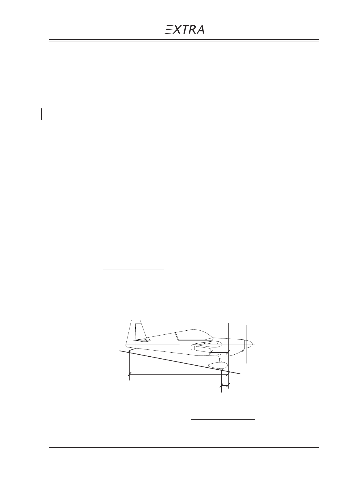
Pilot´s Operating Handbook
EXTRA 200
6.1 GENERAL
This section describes the procedure for establishing the basic weight and moment of the
aircraft. Sample forms are provided for reference. Procedures for calculating the weight and
movement for various operations are also provided. A comprehensive list of all equipment
available for this aircraft is included. It is the responsibility of the pilot to ensure that the
aircraft is loaded properly.
6.2 AIRCRAFT WEIGHING PROCEDURE
The aircraft weight is determined by weighing all three wheel loads simultaneously by three
scales with the aircraft levelled.
(Upper fuselage reference line horizontal)
Datum line for weight arms x is the fire wall.
X1 = distance: fire wall - main wheel
X2 = distance: fire wall - tail wheel
Weight and Balance and Equipment List
Section 6
XN = distance: fire wall - item N
XG = distance: fire wall - Center of Gravity
W1 = Sum of weights indicated by the two scales below the main wheels
W2 = Weight indicated by the scale below the tail wheel
W = Total weight = W1 + W2
XG = (W1 x X1) + (W2 x X2) = C.G. position
W
Reference Firewall (plane)
x
G
x
2
x
W2
W
1
W1
(W1 x X1) + (W2 x X2)
W = W1 + W2 ,
Page Date: 20. April 2002 6 - 3
Page Date: 28. February 2006
XG =
W
Page 74

Section 6
Weight and Balance and Equipment List
If a new weight is added to the known old weight and C.G. position the resulting new weight
and C.G. can be obtained by a simple calculation:
Situation before adding item:
Wo, Xo = Airplane weight, C.G. position
Wn, Xn = Weight, distance from fire wall of item to add
New Weight of airplane and new C.G.:
W = Wo + Wn
XG = Wo x Xo + Wn x Xn : C.G. position
W
6.2.1 OWNERS WEIGHT AND BALANCE RECORD
Enter below all weight change data from aircraft log book.
Pilot´s Operating Handbook
EXTRA 200
EXTRA 200 SERIAL NUMBER: REGISTRATION: D - E J X A
Date Description of Weight change Running empty
modification Added (+), Removed (-) weight
Wt./kg Arm/cm Moment/kg*cm Wt./kg Moment/kg*cm
[lbs] [inch] [lbs*inch] [lbs] [lbs*inch]
06.09.91 Empty weight ___ ___ _______ 671 45067
as delivered
6 - 4 Page Date: 20. April 2002
Page 75
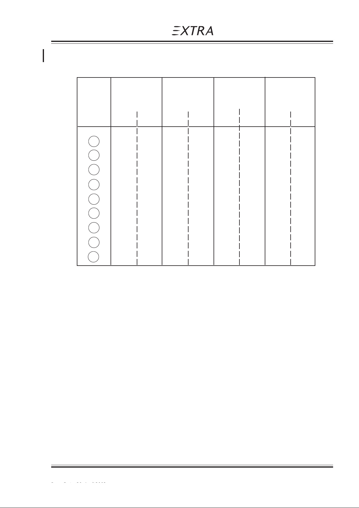
Pilot´s Operating Handbook
EXTRA 200
6.3 CENTER OF GRAVITY CALCULATION (SAMPLE PROBLEM)
PILOT ACRO-TANK COPILOT WING-TANK
Rear Seat Fuel Front Seat Fuel
Position 36 Liter 86 Liter
(9.5 US GAL) (22.6 US GAL)
(kg) (lbs) (kg) (lbs) (kg) (lbs) (kg) (lbs)
190198.5 -- -- --
290198.5 25.9 57.1 -- --
390198.5 25.9 57.1 -- 62136.7
490198.5 --65143.3 --
590198.5 25.9 57.1 65 143.3 --
Weight and Balance and Equipment List
Section 6
690198.5 25.9 57.1 65 143.3 62 136.7
790198.5 --90198.5 --
890198.5 25.9 57.1 90 198.5 --
990198.5 25.9 57.1 90 198.5 62 136.7
Page Date: 20. April 2002 6 - 5
Page Date: 28. February 2006
Page 76
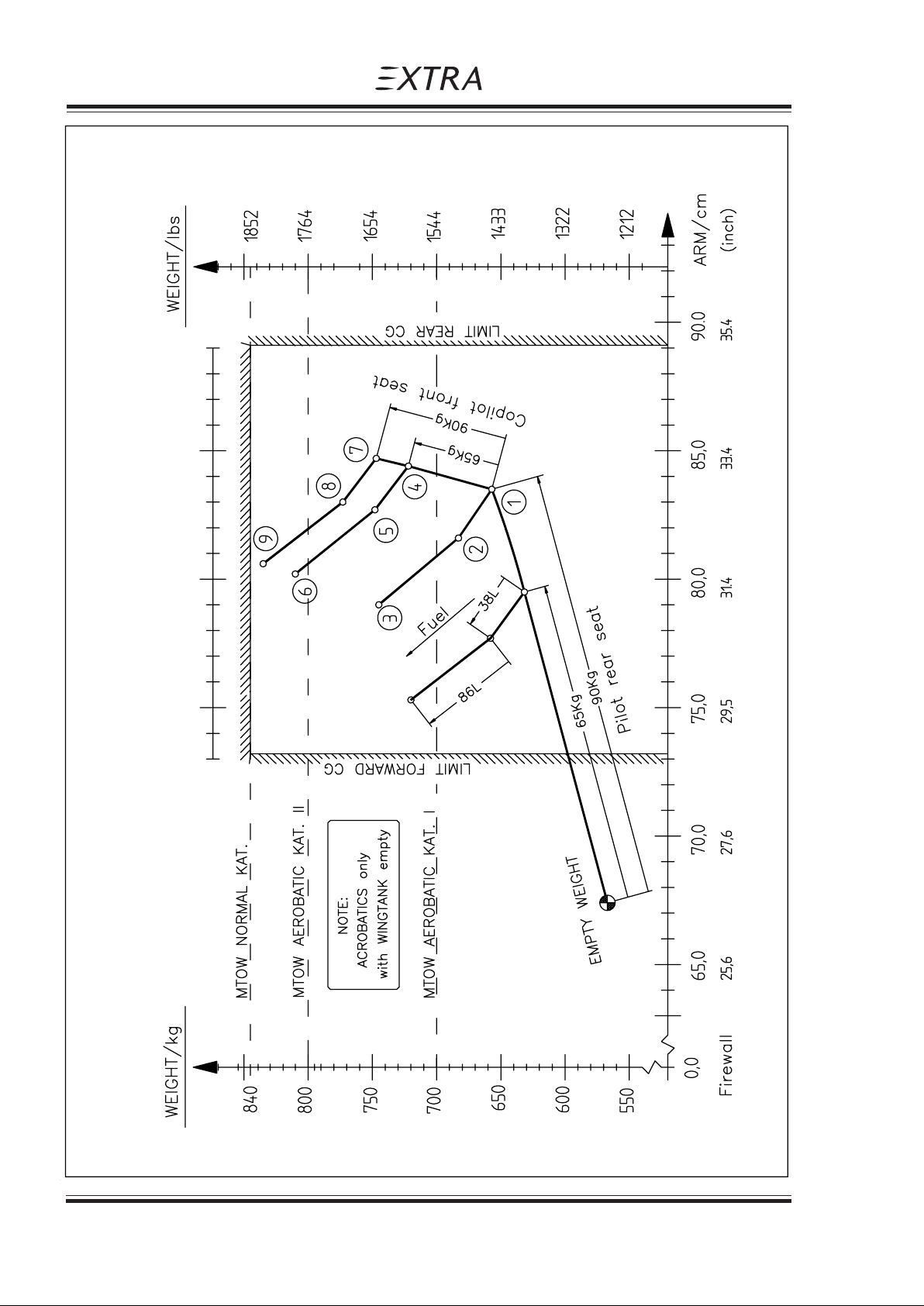
Section 6
Weight and Balance and Equipment List
Pilot´s Operating Handbook
EXTRA 200
6.3 CENTER OF GRAVITY CALCULATION (SAMPLE PROBLEM)
6 - 6 Page Date: 20. April 2002
Page 77

Pilot´s Operating Handbook
EXTRA 200
6.3.1 SAMPLE
Takeoff Condition:
Pilot On Rear Seat 90.0 kg ( 198.5 lbs)
Copilot On Front Seat 65.0 kg ( 143.3 lbs)
"Acro & Center" Fuel 25.9 kg ( 57.1 lbs)
86 l Fuel In Wing Tanks 62.0 kg ( 136.7 lbs)
Aircraft Empty Weight 567.0 kg (1250 lbs)
To find C.G., follow line "Pilot Rear Seat" from Empty Weight to "90 kg" [198.5 lbs] (Point "1").
Continue on line "Copilot Front Seat" to 65 kg (Point "4"). Now follow line "Fuel" via Point "5"
to Point "6":
FIND: Weight ~ 810 kg (1785.7 lbs)
Weight and Balance and Equipment List
Section 6
======== ==========
809.9 kg (1785.6 lbs)
C.G. ~ 80.2 cm (31.5 inch)
6.3.2 WEIGHT AND BALANCE RECORD SHEET
WEIGHT ARM MOMENT
(Kg) (cm) (Kg cm)
EMPTY WEIGHT:
PILOT:
COPILOT:
"ACRO & CENTER" - FUEL:
"WING TANK" - FUEL:
Σ Σ
Σ W =
Σ Σ
Σ Σ
Σ ( W x X )
XG =
Σ Σ
ΣΣ
Σ W
ΣΣ
= _ _ _ cm
Σ Σ
Σ ( W x X ) =
Σ Σ
Page Date: 20. April 2002 6 - 7
Page 78
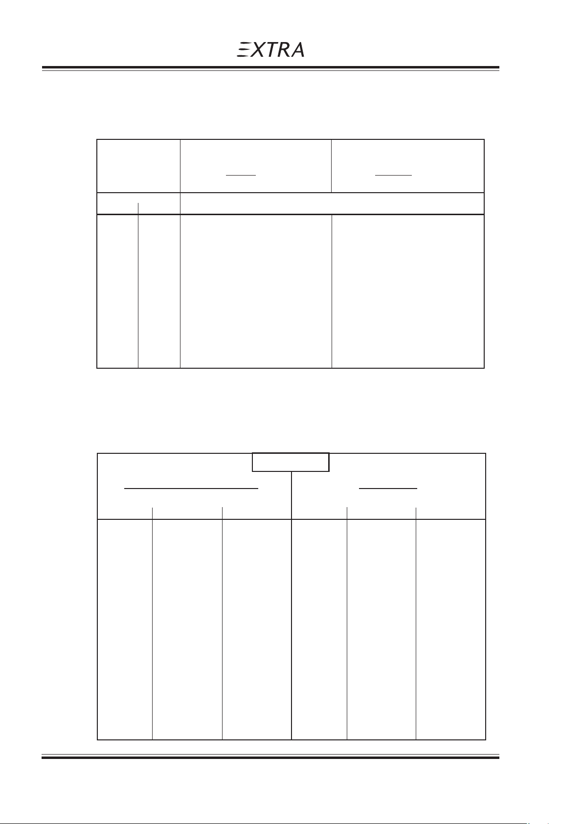
Section 6
Weight and Balance and Equipment List
6.4 LOADING WEIGHTS AND MOMENTS
OCCUPANTS : max. 2
WEIGHT PILOT COPILOT
Pilot REAR SEAT FRONT SEAT
+ Parachute Arm = 185cm (73 inch) Arm = 93.7 cm (37 inch)
KG LBS KG x CM (IN x LBS) MOMENT KG x CM (IN x LBS)
65 143 12012 (10404) 6091 (5275)
70 154 12936 (11204) 6559 (5681)
75 165 13860 (12005) 7028 (6087)
80 176 14784 (12805) 7496 (6493)
85 187 15708 (13605) 7965 (6898)
Pilot´s Operating Handbook
EXTRA 200
90 198 16632 (14406) 8433 (7304)
Fuel in the System: Max. 122 LITERS (32.1 US GAL.)
Fuel
"ACRO & CENTER" TANK WINGTANK
LITER KG KG x CM LITER KG KG x CM
(US GAL) (LBS) (LBS x IN) (US GAL) (LBS) (IN x LBS)
5 (1.3) 3.6 (8) 126 (109) 10 (2.6) 7.2 (16) 361 (312)
10 (2.6) 7.2 (16) 252 (218) 20 (5.3) 14.4 (32) 721 (625)
15 (4.0) 10.8 (24) 378 (327) 30 (7.9) 21.6 (48) 1082 (937)
20 (5.3) 14.4 (32) 504 (437) 40 (10.6) 28.8 (63) 1443 (1250)
25 (6.6) 18.0 (40) 630 (546) 50 (13.2) 36.0 (79) 1804 (1562)
30 (7.9) 21.6 (48) 756 (655) 60 (15.8) 43.2 (95) 2164 (1875)
36 (9.5) 25.9 (58) 932 (799) 70 (18.5) 50.4 (111) 2525 (2187)
80 (21.1) 57.6 (127) 2886 (2499)
86 (22.7) 61.9 (136) 3102 (2687)
6 - 8 Page Date: 20. April 2002
Page 79
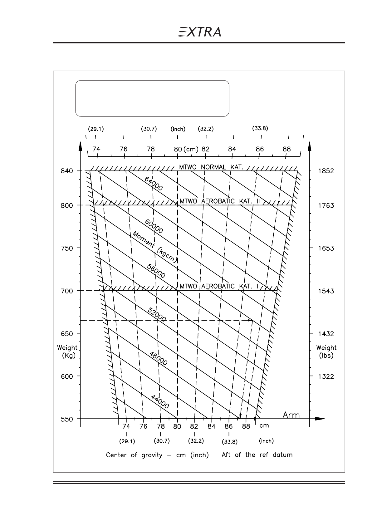
Pilot´s Operating Handbook
EXTRA 200
6.5 WEIGHTS AND MOMENTS LIMITS
Example:
At 655 kg and 58000 kgcm the C.G. location is
87.0 cm aft of ref. datum
Weight and Balance and Equipment List
Section 6
Page Date: 20. April 2002 6 - 9
Page 80
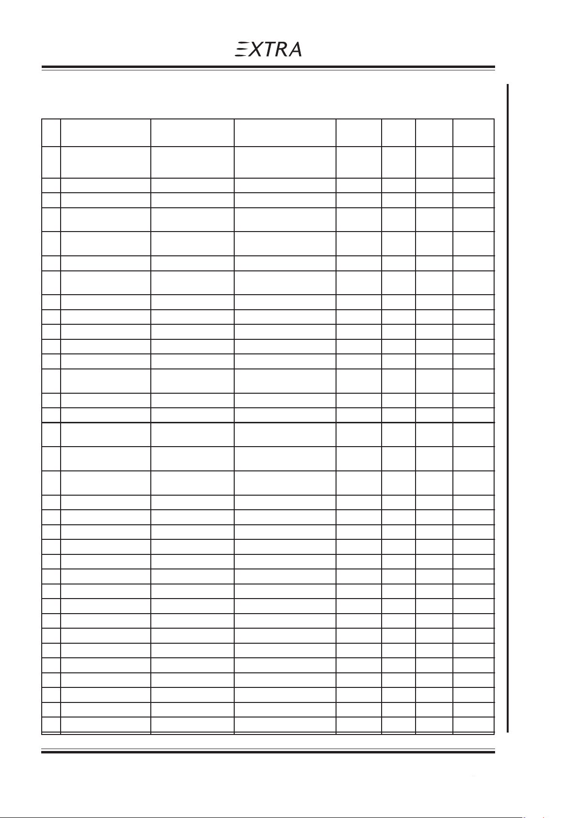
Section 6
Weight and Balance and Equipment List
Pilot´s Operating Handbook
EXTRA 200
6.6 EQUIPMENT LIST
QTY ITEM MANUFACT PART NUMBER WEIGHT ARM Mark if Required (R)
1 Engine Lycoming AEIO-360-A1E 128.40 -0.51 R
1 Magneto, LH Slick 4372 2.30 -0.22 R
1 Magneto, RH Slick 4370 2.00 -0.22 R
4 Shock Mounts Lord J-7402-37 1.70 -0.29 R
4 Shock Mounts Barry Controls 94150-02 1.70 -0.29 A
1 Exhaust System Gomolzig EA200-606000 7.35 -0.29 R
4 in 1
1 Exhaust System Gomolzig EA200-606000/1 7.90 -0.27 O
4 in 1 with Silencer
1 Starter Lycoming MZ 4221 8.15 -0.67 R
1 Starter, lightweight SKY-TEC 149-12 LS 3.65 -0.75 A
(Lycoming) (31A22 104)
1 Fuel Injector Bendix RSA-5 AD 1 3.46 -0.57 R
1 Elec. Fuel Pump Weldon Tool 8120-M 1.10 -0.04 R
1 Elec. Fuel Pump Weldon Tool B8120-M 1.10 -0.04 A
1 Fuel Selector Allen 6 S 122 0.19 0.26 R
1 Oil Cooler Stewart Warner 8406 R 1.40 -0.77 R
1 Propeller MT-Propeller MTV-12-B-C / C183 - 17e 22.90 -1.02 R
1 Spinner Mühlbauer P-440 R
1 Governor Woodward D 210 982 1.10 -0.79 R
1 Governor MT-Propeller P-880-3 1.10 -0.79 A
1 Set Fuel, Oil & Sense Aeroquip Type 303 6.15 -0.21 R
Hoses in Eng. Comp. with Firesleeve AE 102
1 Set Fuel Hoses Aeroquip Type 303 1.38 0.21 R
in Cabin Comp.
1 Sense Hoses (Cabin) Knapp/Hoerbiger HS3AM and H3MM 0.30 0.77 R
(Oil, Fuel & MA Press)
1 RPM Vernier Control ACS Products Co. A-750-30-1200 0.71 0.55 R
1 RPM Vernier Control ACS Products Co. A-750-30-960 0.60 0.49 A
1 Mixture Vernier Control ACS Products Co. A-750-20-1080 0.65 0.68 R
1 Mixture Vernier Control ACS Products Co. A-750-20-960 0.60 0.60 A
1 Throttle Control Teleflex Marine F303 02750 0.50 0.60 R
1 Altimeter, front United Instr. UI5934PD-3 A.134 0.60 0.52 O
1 Altimeter, front (metric) Winter 4110 0.33 0.55 O
1 Altimeter, rear United Instr. UI5934PD-3 A.134 0.60 1.50 R
1 Altimeter, rear (metric) Winter 4110 0.33 1.50 A
1 Altitude Blind Encoder ACK A-30 0.15 1.26 O
1 Airspeed Indicator, front Winter 6533 422 0.21 0.52 O
1 Airspeed Indicator, front United Instr. UI8030 B.871 0.22 0.52 O
1 Airsp. Ind, front (metric) Winter 6531 422 0.21 0.52 O
1 Airspeed Indicator, rear Winter 6533 422 0.21 1.50 R
1 Airspeed Indicator, rear United Instr. UI8030 B.871 0.22 1.50 A
1 Airsp. Ind., rear (metric) Winter 6531 422 0.21 1.50 A
EXTRA-200 S/N:
(KG) (m) installed Optional (O)
Alternate (A)
6 - 10 Page Date: 20. April 2002
Page Date: 28. February 2006
Page 81

Pilot´s Operating Handbook
EXTRA 200
Weight and Balance and Equipment List
Section 6
QTY ITEM MANUFACT PART NUMBER WEIGHT ARM Mark if Required (R)
(KG) (m) installed Optional (O)
Alternate (A)
1 RPM Indicator VDO 333 230 115 002 0.31 1.49 R
or 333 035 001G
1 RPM Indicator digital Horizon P100-230-464-00 0.68 1.49 A
1 Magnetic Compass Airpath C 2300 0.25 1.50 R
1 Accelerometer Kollsman or Pioneer AN 5745 0.37 1.50 O
or Bendix
1 Accelerometer EXTRA DSA 12 0.37 1.49 O
1 Accelerometer EZE Technologies DA-55 0.16 1.49 O
1 Turn & Bank Indicator United Instr. 9501-2 / TSO C3b 0.55 1.50 O
1 Turn & Bank Indicator Castleberry C101 / TSO C101T 0.55 1.50
1 VHF RADIO Becker AR 3201 0.90 1.46 R
1 VHF RADIO Becker AR 4201 0.90 1.46 A
1 GPS / NAV / COM Garmin GNS 430 2.95 1.40 O
1 Transponder King KT 76A 0.89 1.40 O
1 Transponder Garmin GTX 327 0.95 1.40 O
1 Transponder Filser TRT-600 (LAST) 0.70 1.45 O
1 Transponder Filser TRT-800 0.70 1.45 O
1 Transponder Garmin GTX 330 1.50 1.40 O
1 Transponder Bendix/King KT 73 1.64 1.40 O
1 Transponder Becker BXP6401-1 0.80 1.45 O
1 Transponder Becker BXP6401-2 0.80 1.45 O
1 Transponder Becker ATC-2000 1.20 1.40 O
1 Transponder Becker ATC-4401 0.73 1.45 O
1 Transponder Antenna Comant Industries CI 105 0.11 0.08 O
1 Transponder Antenna Bendix/King KA 60 0.11 0.08 O
1 COM Antenna Moba 210FA 0.10 4.02 R
1 COM Antenna EXTRA 83205A 0.10 4.02 A
1 COM Antenna Pointer P1 3001-10 0.05 4.02 A
1 ELT Pointer 3000-10 1.00 2.60 O
1 Oil-Press. Indicator UMA 3-311-32 or 10-12400 0.05 1.52 R
1 Oil Press./Oil Temp Ind. Amitek or Christen 61943 0.51 1.52 A
1 Oil Temp. Indicator Westach 2A9-2 0.05 1.52 R
1 Oil Temp Sensor Westtach W399-S9 0.08 -0.20 R
1 Oil Press./ Westach 3DA3-3MM or 3DA3-3KV 0.14 1.50 A
Oil Temp. Ind. (3 1/8")
1 Oil Temp. Sender Westach W399-S9 0.08 -0.20 A
1 Oil Press Sensor Westach 387-100MM or 387-100KV 0.12 0.04 A
or 387-11MM
or Mediamate 9308704 0.12 0.04 A
1 Oil Press / Westach 2DA3-3MM or 2DA3-3KV 0.09 1.50 A
Oil Temp Ind. (2 1/4")
1 Oil Temp. Sender Westach W399-S9 0.08 -0.20 A
1 Oil Press Sensor Westach 387-100MM or 387-100KV 0.12 0.04 A
or 387-11MM
or Mediamate 9308704
Page Date: 28. February 2006
Page Date: 20. April 2002 6 - 11
Page 82

Section 6
Weight and Balance and Equipment List
Pilot´s Operating Handbook
EXTRA 200
QTY ITEM MANUFACT PART NUMBER WEIGHT ARM Mark if Required (R)
(KG) (m) installed Optional (O)
Alternate (A)
1 EGT/CHT Indicator Westach 2 DA 1 0.07 1.52 O
1 EGT Probe Westach 712-2 DWK 0.06 -0.46 O
1 CHT Probe Westach 712-7 DK 0.05 -0.50 O
1 Manifold press. UMA 7-100-20 0.13 1.52 R
Indicator
1 Fuel Pressure Ind. UMA 3-313-10 0.05 1.52 R
1 Man Press / Fuel Press United Instr. UI6331 H.52 0.54 1.50 A
1 Man Press / Fuel Flow United Instr. UI6331 H.212 0.54 1.50 A
1 Fuel Cont. Probe Wing VDO 226 801 015 001 G 0.12 0.51 R
(Wing Tank)
1 Fuel Cont. Ind. Wing VDO 301 271 036 001 K 0.08 1.50 R
(Wing Tank) or 301 030 001 G
1 Fuel Cont. Probe VDO 224 082 006 097 R 0.20 0.36 R
Acro & Center Tank
1 Fuel Cont. Ind. VDO 301 272 052 001 K 0.14 1.50 R
Acro & Center Tank or 301 030 002 G
1 Ammeter VDO 190 004 039 002 0.08 1.50 R
or 190 037 002 G
1 Volt/Ammeter Electronics Intern. VA-1A 0.26 1.51 A
1 Volt/Ammeter Electronics Intern. VA-1A-50 0.22 1.50 A
1 Shunt Electronics Intern. S-50 0.09 1.40 A
1 Alternator 60Amp Electrosystems ALX 8421 LS 5.90 -0.69 R
1 Voltage Regulator Lamar B-00371-25 0.15 0.02 R
1 Low Vol. Monitor Lamar B-00378-4 0.03 0.02 R
1 Alternator 65 Amps Bosch 0 120 489 935 4.60 -0.72 A
1 Alternator 55 Amps Bosch 0 120 489 917 4.20 -0.72 A
1 Alternator 55 Amps Bosch 0 120 489 469 4.20 -0.72 A
1 Battery Sonnenschein DRYFIT A212/24G 8.60 -0.11 R
1 Battery Hagen HDSM-12250 9.70 -0.11 A
1 Battery Exide/Sonnenschein Dryfit A512/25G5 9.65 -0.11 A
1 Battery B&C BC100-MJ 11.29 -0.11 A
1 Batt. Charger Plug EXTRA 146 19 20 0.02 0.26 O
1 External Power Recept. Diverse AN 2552-3A 1.46 1.77 O
1 Ext. Power Solenoid Switches Kidde 22735 0.40 -0.03 O
1 Ext. Power Solenoid White-Rodgers 70-111-225-5 0.40 -0.03 O
(cont. operation)
1 Main Bus Solenoid White-Rodgers 70-111-226-5 0.40 -0.03 R
1 Starter Solenoid Switches Kidde 22735 0.40 -0.03 R
1 Ignition switch TCM 10-357200-1 0.15 1.50 R
1 Main Bus Fuseholder MTA PN 03.00360 0.03 -0.01 O
1 Main Bus Strip Fuse MTA PN 02.00300 -0.01 O
(40 Amps)
1 PCB Auto Fuse EXTRA 83290.1 0.01 -0.03 O
1 Low Voltage Light OAK MS 25041-2 0.02 1.53 R
1 Switches Cutler Hammer div. 0.04 1.52 R
3 Circuit Breakers Potter&Brumfield div. 0.14 1.51 R
5 Switch/Circuit Breakers Potter&Brumfield div. 0.25 1.51 R
6 - 12 Page Date: 20. April 2002
Page Date: 28. February 2006
Page 83

Pilot´s Operating Handbook
EXTRA 200
Weight and Balance and Equipment List
Section 6
QTY ITEM MANUFACT PART NUMBER WEIGHT ARM Mark if Required (R)
(KG) (m) installed Optional (O)
Alternate (A)
1 Strobe Light (single) Whelen A 470-W 0.13 0.85 R
1 Strobe Power Supply Whelen A490 T 0.27 0.85 R
2 Strobe/Nav LTS (RH/LH) Whelen A 600-PG/PR-14 0.23 0.80 A
2 Strobe Power Supply Whelen A 490 T 0.54 0.80 A
1 Stall Sensor EXTRA 73106.1 0.07 0.42 R
1 Stall Warn Horn EMAG EM-S 110P 0.13 1.37 R
2 Main Wheel Tires Diverse 5.00-5 / 6PR 3.90 0.35 R
2 Main Wheel Rim Cleveland 40 - 151 4.00 0.35 R
2 Brake Assy Cleveland 30 - 164 1.40 0.35 R
2 Brake Cylinder front Cleveland 10 - 20 E 0.55 0.15 R
2 Brake Cylinder rear Cleveland 10 - 20 E 0.55 0.95 R
2 Brake Cylinder front Matco MC4E 0.55 0.15 A
2 Brake Cylinders rear Matco MC4E 0.55 0.95 A
1 Tail Wheel 5" EXTRA steerable 5.50 4.70 A
1 Tail Wheel 6" Assy Special Products 5.90 4.70 A
(Soft) Aviation Inc.
1 Brake Fluid Reservoir ACS A-315 0.20 -0.04 R
1 Safety Belt Hooker 1 013 030 2.90 1.10 R
Assy. Front
1 Safety Belt Hooker 1 011 230 3.30 1.80 A
Assy. Front With Ratchet
1 Safety Belt Hooker 1 011 230 3.30 1.80 R
Assy. Rear With Ratchet
1 Standard Canopy EXTRA 27301.000-LV 11.00 1.45 R
1 Single Seat Canopy EXTRA 87410.000-LV 9.20 1.45 O
1 Long Range Tank EXTRA 87901 1.80 0.62 O
1 Leather Interior EXTRA Assy 1.50 1.55 O
1 Aresticard Holder EXTRA Assy 0.09 1.51 O
1 Airtow Hook EXTRA/TOST 83607A0 0.50 5.05 O
1/2 Sighting Device LH/RH EXTRA 84801.10 each 0.44 1.53 O
2 Wing Tie Down Rings EXTRA 83801.2-01 0.04 1.18 O
1 Rear Seat Pan Stand. EXTRA 77201.4 1.40 1.94 R
1 Rear Seat Pan Adjust. EXTRA 87403.1 1.40 1.94 A
1 Horizontal Tail Standard EXTRA 37201.1 20.00 4.24 R
1 Horizontal Tail (CRP) EXTRA 87932 19.00 4.25 A
1 Vertical Tail Standard EXTRA 37101.1 9.80 4.54 R
1 Vertical Tail (CRP) EXTRA 87931 9.00 4.54 A
Page Date: 28. February 2006
Page Date: 20. April 2002 6 - 13
Page 84

Section 6
Weight and Balance and Equipment List
Pilot´s Operating Handbook
EXTRA 200
Left blank intentionally
6 - 14 Page Date: 20. April 2002
Page Date: 28. February 2006
Page 85

Pilot´s Operating Handbook
EXTRA 200
Description and Operation of Aircraft and Systems
Section 7
SECTION 7
DESCRIPTION AND OPERATION
OF AIRCRAFT AND SYSTEMS
Table of Contents
Paragraph Page
SECTION 7 DESCRIPTION AND OPERATION OF AIRCRAFT AND SYSTEMS
7.1 THE AIRCRAFT .................................................................................................................. 7-3
7.2 FUSELAGE ......................................................................................................................... 7-3
7.3 WINGS ................................................................................................................................7-4
7.4 EMPENNAGE ..................................................................................................................... 7-4
7.5 FLIGHT CONTROL SYSTEM............................................................................................. 7-5
7.5.1 Primary Control System....................................................................................................... 7-5
7.5.2 Longitudinal Flight Control System ...................................................................................... 7-5
7.5.3 Lateral Flight Control System .............................................................................................. 7-5
7.5.4 Directional Flight Control System ........................................................................................ 7-5
7.5.5 Secondary Control...............................................................................................................7-5
7.6 INSTRUMENTATION .......................................................................................................... 7-6
7.6.1 Instrument Panel (Rear Cockpit) ......................................................................................... 7-6
7.6.2 Instrument Panel (Front Cockpit)......................................................................................... 7-8
7.7 LANDING GEAR................................................................................................................. 7-8
7.8 SEA TS, SEA T BELTS ......................................................................................................... 7-9
7.9 CANOPY ............................................................................................................................. 7-9
7.10 POWER PLANT................................................................................................................ 7-10
7.10.1 Engine ............................................................................................................................... 7-10
7.10.2 Oil System......................................................................................................................... 7-11
7.10.3 Engine Installation ............................................................................................................. 7-11
7.10.4 Propeller ............................................................................................................................ 7-11
7.10.5 Throttle .............................................................................................................................. 7-11
7.10.6 Mixture .............................................................................................................................. 7-11
7.10.7 RPM-Control ..................................................................................................................... 7-11
7.10.8 Fuel Selector V alve............................................................................................................7-12
7.10.9 Exhaust System (optional)................................................................................................. 7-12
7.11 FUEL SYSTEM ................................................................................................................. 7-12
7.12 ELECTRICAL SYSTEM .................................................................................................... 7-13
7.13 CABIN ENVIRONMENT CONTROL ................................................................................. 7-15
Page Date: 28. February 2006
Page Date: 20. April 2002 7 - 1
Page Date: 28. February 2006
Page 86

Section 7
Description and Operation of Aircraft and Systems
Pilot´s Operating Handbook
EXTRA 200
Left blank intentionally
7 - 2 Page Date: 20. April 2002
Page 87
Pilot´s Operating Handbook
EXTRA 200
7.1 THE AIRCRAFT
The aircraft EXTRA 200 is designed and developed by EXTRA Flugzeugproduktions- und
Vertriebs- GmbH, Dinslaken 46569 Hünxe, Federal Republic of Germany, in accordance
with the U.S. Federal Aviation Regulations, part 23, categories normal and acrobatic to fulfil
the primary flight training, normal operation rules and acrobatic training up to the unlimited
acrobatic level.
EXTRA 200 is a light weight, robust, single piston-engined, two-seat aircraft with a fuselage
structure in tig-welded steel-tube construction.
Description and Operation of Aircraft and Systems
Section 7
SECTION 7
DESCRIPTION AND OPERATION
OF AIRCRAFT AND SYSTEMS
The landing gear, wing, and tail are made of epoxy, reinforced with glass- and carbonfiber.
The items are qualified up to 72°C (161,6°F). Not to exceed this temperature limit an appropriate colour specification for composite structure is given by the manufacturer document
EA-03205.19.
To check the temperature inside the cockpit (potential "green house" effect) a reversible
temperature indicator (STRUCTURAL OVERHEAT INDICATOR) is applied on the upper
side of the wing main spar in the carry-through section. After reaching the temperature limit
of 72°C (161,6°F) the word "RISK" appears on the red spot of this structural overheat
indicator immediately and flying is prohibited. When the structure cools down below this
temperature limit the word "RISK" disappears and you may go on with the preflight checklist.
a) Below 72°C (161,6°F) b) At 72°C (161,6°F) or above
STRUCTURAL
OVERHEAT
INDICATOR
EXTRA
CAUTION:
While the word
RISK
appears, flying
is prohibited !
STRUCTURAL
OVERHEAT
INDICATOR
EXTRA
RISK
CAUTION:
While the word
RISK
appears, flying
is prohibited !
The standard aircraft is designed to operate within a range of ambient air temperature from 20°C to +44°C (-4°F to 111°F) at sea level. It is possible to start the engine using the aircraft
battery at -20°C (-4°F) without preheating. Below -10°C (+14°F) OAT a special oil breather
line must be adapted (available as kit).
7.2 FUSELAGE
The fuselage structure consists of a steel tube construction integrating the wing and empennage connections as well as the seats. The fuselage except the rear lower part, is faired
with an aramid/carbon laminate shell. Within the exhaust area stainless steel sheet metal is
used. The upper fuselage body surface is one part from firewall to vertical stabilizer including the correlated canopy frame. Only the lower rear part of the fuselage is covered with
Ceconite® 102.
Page Date: 28. February 2006
Page Date: 20. April 2002 7 - 3
Page 88

Section 7
Description and Operation of Aircraft and Systems
The canopy frame itself is constructed by carbon laminate. The canopy is one part, opens to
the right and is held in the open position by a belt. Emergency jettisoning is achieved by
simply unlatching the canopy. For additional pilots protection a roll bar is installed behind the
rear pilots seat.
7.3 WINGS
The wing is of CRP construction. The dual chamber main spar - fulfilling the requirement for
fail safe design - consists of carbon roving caps combined with CRP webs. Core foam is a
PVC foam (Divinycell HT 50). The wing shell is built by a Honeycomb sandwich with CRP
Laminates. On the surface there is a protective layer of GRP. To prevent buckling of the
shell plywood ribs are used. In the area of the wingtanks is a layer of CRP laminate with an
incorporated aluminium thread bonded to the metal fuselage structure as means of lightning
protection.
The connection to the fuselage is arranged by two bolts piercing through the spar parallel to
the centerline of the fuselage and two brackets at the rear spars. Integral fuel cells are
provided in the leading edge of the wing extending from the root ribs to half the span of each
R/L and L/H wing. The ailerons are supported at three points in spherical bearings pressed
into aluminium brackets. To reduce pilot's hand forces the hinge line of the ailerons is
positioned 25% of the aileron depth at the root and 21,5% at the tip. Furthermore the ailerons are equipped with "spades" to decrease pilot forces. Ailerons are controlled via the
center bracket. To prevent flutter the ailerons are weight balanced in the overhanging
leading edge.
Pilot´s Operating Handbook
EXTRA 200
7.4 EMPENNAGE
The EXTRA 200 possesses a cruziform empennage with stabilizers and moveable control
surfaces. The rudder is balanced aerodynamically at the tip. Spars consist of PVC foam
cores, CRP caps and GRP laminates. The shell is built by honeycomb sandwich with GRP
laminates. Buckling is prevented by plywood ribs.
Deviating from the other control surfaces the spar webs of the surfaces of the elevator is
built by CRP. On the R/H elevator half a trim tab is fitted with two hinges. The control surfaces are mounted in spherical bearings (exception: Trim tab). To prevent flutter rudder and
elevator are mass balanced. The balance weight for the rudder is installed in the rudder tip
while the balance weight for the elevator is mounted on the elongated center bracket of the
elevator extending into the fuselage.
7 - 4 Page Date: 20. April 2002
Page 89

Pilot´s Operating Handbook
EXTRA 200
7.5 FLIGHT CONTROL SYSTEM
7.5.1 PRIMARY CONTROL SYSTEM
The EXTRA 200 is standard equipped with full dual primary flight controls including conventional stick-type control columns and adjustable rudder pedals. The primary control surfaces
are operated through a direct mechanical linkage.
7.5.2 LONGITUDINAL FLIGHT CONTROL SYSTEM
The two control columns are interconnected by a torque tube. The control movements are
from there transferred to the elevator by a push rod.
7.5.3 LATERAL FLIGHT CONTROL SYSTEM
Push and pull rods are connected by sealed ball bearings from the torque tube to the
ailerons.
The ailerons are statically as well as dynamically balanced. (Dynamically with spades).
Description and Operation of Aircraft and Systems
Section 7
The ailerons are supported by lubricated, sealed bearings.
7.5.4 DIRECTIONAL FLIGHT CONTROL SYSTEM
The dual rudder pedals with brake pedals are adjustable and operate the rudder through a
cable system. Springs keep the cables under tension when they are not operated.
7.5.5 SECONDARY CONTROL
The elevator trim control is located on the right side in the rear cockpit.
The canopy lock is operated from the outside by a handle on left side of the canopy by
reaching into the cockpit through the window. Inside a handle is located in both cockpits,
used for locking as well as for normal operation and for emergency release.
The starter/magneto switch is located on the left side of the instrument panel in front of the
rear seat.
Page Date: 20. April 2002 7 - 5
Page 90
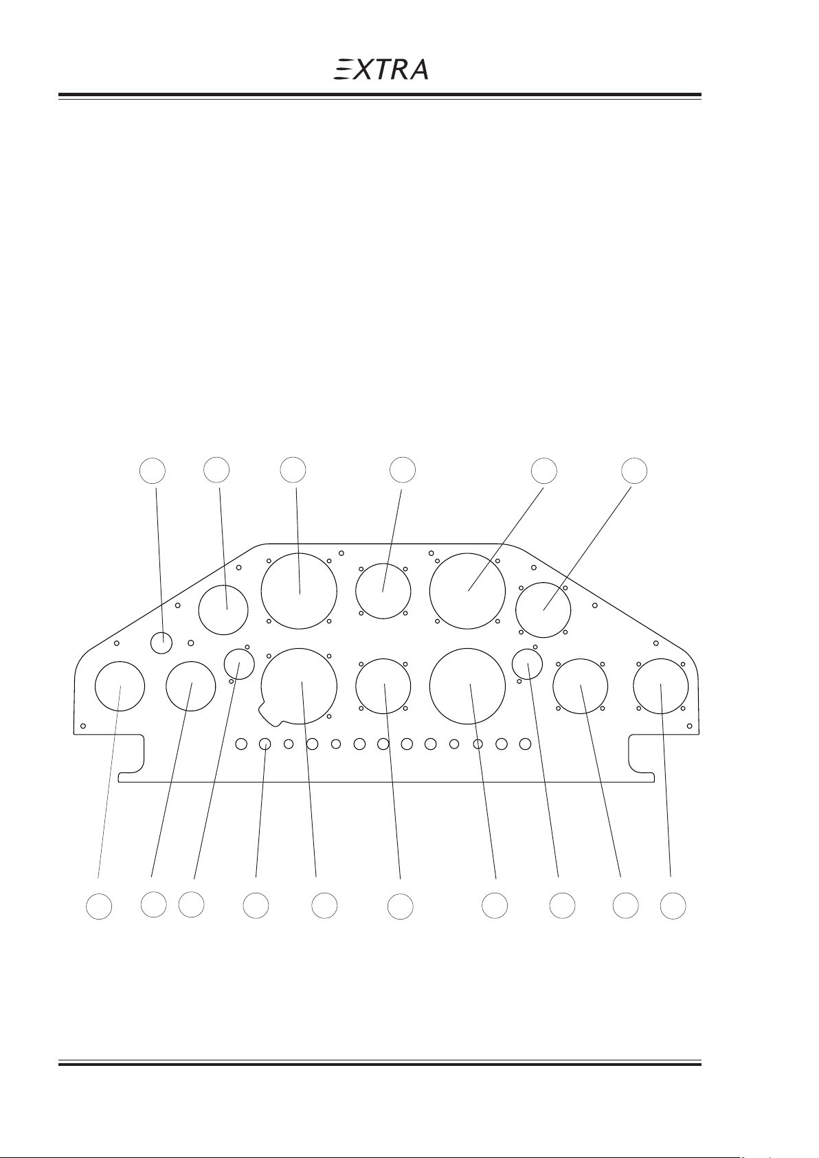
Section 7
Description and Operation of Aircraft and Systems
7.6 INSTRUMENTATION
The EXTRA 200 is equipped with flight instruments in both cockpits.
Instruments and placards can be provided with markings in either metric or English units. The
colour markings in instruments follow US-FAR, part 23 recommendation ( see section 2 ).
7.6.1 INSTRUMENT PANEL (REAR COCKPIT)
For instrumet panel arrangement of the reat cockpit refer to Fig. 7.6.1, which includes
standard and optional equipment marked as such.
Fig. 7.6.1:
Pilot´s Operating Handbook
EXTRA 200
1 2 3 4 5 6
16 15 14 13 12 11 10 9 8 7
7 - 6 Page Date: 20. April 2002
Page 91

Pilot´s Operating Handbook
EXTRA 200
Standard Optional Position Item
x 1 Magneto Selector switch & starter
x 2 Amperemeter
x 3 Airspeed indicator
x 4 Magn. Direction indicator
x 8 Oil temperature
x 9 Oil pressure
x 10 RPM indicator
x 11 Manifold pressure
x 12 Altimeter
x 13 Switches / Circuit breaker
x 14 Fuel pressure
x 15 Fuel Quantity "Acro & Center" Tank
x 16 Fuel Quantity "Wing Tank"
Description and Operation of Aircraft and Systems
Section 7
x 5 g-meter
x 6 EGT / CHT
x 7 COM
x 17 Vertical speed indicator
x 18 Turn and bank indicator
x 19 Artificial horizon
x 20 Intercom button
x 21 Directional gyro
x 22 RPM control, Prop governor
x 23 Mixture control
x 24 Throttle lever
x 25 Stick
x 26 Radio button
x 27 Fuel shutoff valve
x 28 Trim lever and indicator
x 29 Boost pump
NOTE
This list may be modified by the minimum equipment requirements of individual
certifying authorities!
Page Date: 20. April 2002 7 - 7
Page 92

Section 7
Description and Operation of Aircraft and Systems
7.6.2 INSTRUMENT PANEL (FRONT COCKPIT)
The front instrument panel respectively the front cockpit is equipped with the following
positions.
24 Throttle
25 Stick
27 Fuel shutoff valve
The following equipment is optional:
3 Airspeed indicator
4 Magn. Direction indicator
5 g-meter
10 RPM indicator
12 Altimeter
17 Vertical speed indicator
18 Turn and bank indicator
19 Artificial horizon
20 Intercom button
21 Directional gyro
26 Radio button
Pilot´s Operating Handbook
EXTRA 200
7.7 LANDING GEAR
The landing gear is a composite construction with a multichamber fibreglass spring in a tailwheel design.
The main wheels have a size of 5-5.50 and they are equipped with hydraulic disc brakes.
The tail wheel has a solid rubber tire with full-swivel capability.
7 - 8 Page Date: 20. April 2002
Page 93

Pilot´s Operating Handbook
EXTRA 200
7.8 SEATS, SEAT BELTS
The seats are ergonomically shaped composite designs. The back rest is adjustable on the
ground with 2 quickpins in different positions and angle. The rear pedal-to-seat distance can
be varied in different positions. In the front cockpit there is no possibility to adjust either the
pedals nor the seat. The seat belt assembly consists of a left and a right shoulder strap, two
left and two right lap belts and a negative-g-strap. All belts are adjustable. As each lap belt
features a single point release, they are redundant for safety during aerobatics maneuvers.
If one release is opened unintentionally, the second one guarantees full safety. For safe
operation the releases are arranged in a way that one has to be closed to the right side, the
other one to the left. During acrobatic maneuvers the seat belt system should be tightened
firmly.
7.9 CANOPY
The canopy of front and rear cockpit is manufactured in one section. The canopy can be
manually operated and opened by lifting to the right.
In the open position there is a rod mounted to the fuselage rear of the canopy which must be
connected to the canopy preventing slam down unintentionally.
Interior canopy locking handles, located on the left side on the canopy of each cockpit must
be pulled together to unlock the canopy from the inside.
To open the canopy from the outside there are no separate handles, this means it must be
opened by reaching through the small window (bad weather window) and proceed as
mentioned above (interior opening).
Description and Operation of Aircraft and Systems
Section 7
Page Date: 20. April 2002 7 - 9
Page 94

Section 7
Description and Operation of Aircraft and Systems
7.10 POWER PLANT
7.10.1 ENGINE
The power plant consists of one Textron-Lycoming six-cylinder, horizontally opposed, aircooled, direct drive, fuel injection engine type with inverted oil system.
The rated maximum T/O Power is 200 HP at 2700 RPM.
Engine specification:
Textron-Lycoming AEIO-360-A1E
For the present TBO refer to latest issue of Textron - Lycoming
SERVICE LETTER No. L 201.
The following accessories are included in the power plant
installation:
Pilot´s Operating Handbook
EXTRA 200
Fuel Injector: Bendix
Magnetos: Slick
Alternator: Electrosystems
Starter: Lycoming
Fuel pump: Gates Lear
Shielded ignition system
Propeller governor drive
Transistor voltage regulator
Overvoltage relay
The engine is operated with the following manual controls:
Throttle control, dual
RPM control
Fuel mixture control
The propeller governor monitors the RPM automatically
and prevents overspeeding. In the event that oil pressure is lost
the propeller is automatically adjusted to coarse pitch in order
to avoid overspeeding.
The use of 100/100LL aviation grade fuel (AVGAS 100) is the minimum grade
recommended by the manufacturer of the AEIO-360-A-1E engine.
For continuous operation 115/145 aviation fuel is the maximum
grade.
7 - 10 Page Date: 20. April 2002
Page Date: 28. February 2006
Page 95

Pilot´s Operating Handbook
EXTRA 200
7.10.2 OIL SYSTEM
The oil is cooled by an oilcooler mounted on the left hand side in the engine compartment.
The oil level is determined by a dip-stick.
A thermostatic valve is fitted upstream of the oil cooler. This valve ensures a quick warm-up
of the oil after engine start.
Oil capacity and grades:
Oil:
Max sump capacity 8 qts.
Min sump capacity Acrobatic 6 qts.
For temperatures and oil grades refer to Section 1.7.
Description and Operation of Aircraft and Systems
Section 7
Normal 4 qts.
7.10.3 ENGINE INSTALLATION
The engine is supported by four shock mounts (type LORD or BARRY CONTROLS), to the
tig-welded steel tube engine mount which is attached to the fuselage with four bolts on the
firewall axis.
The engine cowling is divided into two parts, a lower and an upper part both made of glassfibre/carbonfibre reinforced epoxy. The parts are fixed by a number of screws and the upper
cowling has a separate hatch for easy access to the oil dip-stick.
7.10.4 PROPELLER
The standard propeller is a 3-blade wood composite, constant speed propeller
type MTV-12-B-C/C183-17e. The propeller has a diameter of 1,83 m.
7.10.5 THROTTLE
Dual control (cub-type) mounted on the left side in cockpit.
7.10.6 MIXTURE
Vernier-control located at left side of rear cockpit (red knob).
7.10.7 RPM-CONTROL
Vernier-control on the left side of the rear cockpit.
Preselection of RPM possible due to constant speed governor (blue knob).
Page Date: 20. April 2002 7 - 11
Page 96

Section 7
Description and Operation of Aircraft and Systems
7.10.8 FUEL SELECTOR VALVE
Dual control. A rotary fuel selector valve is mounted behind the firewall on the right side of
the fuselage. A torque tube connects the valve to both cockpit handles. Pull and turn the
handle 90° to open the valve to the Acro & Center tank. A further 90° turn switches to the
Wing tank fuel supply.
Position down: "OFF"
Position left: "ACRO & CENTER"
Position up: "WING TANK"
7.10.9 EXHAUST SYSTEM (OPTIONAL)
The EXTRA 200 can be equipped with a complete 4 in 1 System including silencer.
7.11 FUEL SYSTEM
The fuel system consists of two separate, independent tanks:
Pilot´s Operating Handbook
EXTRA 200
- "Acro & Center tank" in the fuselage
- "Wing tank" in the wing
Wing tank:
The root section of each wing in front of the main spars forms an integral fuel tank providing
two interconnected tanks with 86 liters (22.7 US Gal.) total capacity. Each side of the wing
has a 2" diameter filler cap for gravity refuelling. Due to the interconnection the fuel level of
the left and right integral tank will equalize during refuelling within reasonable time. For max.
fuel capacity, the first filled side have to be filled once again! Furthermore the wing tank is
connected directly to the engine by the fuel selector valve. Unusable fuel is approximately 1
liter (0.3 Us Gal.).
Acro & center tank:
The Acro tank of 9 liters (2,3 US Gal.) is mounted under the Center tank. This Center tank
of 27 liters (7.1 US Gal.) is mounted in front of the main spar of the wing. The Acro tank is
connected with the Center tank in a gravity feed system. The Center tank has a 2" diameter
filler cap for gravity refuelling. Unusable fuel is approximately 4 liters (1.1 US Gal.)
Adequate venting is provided in each tank by a main ventilation-tube, ending outside the
fuselage at the right side.
Fuel pump
In addition to the engine driven fuel pump an electrically driven auxiliary fuel pump (boost
pump) with by-pass, having sufficient capacity to feed the engine at takeoff power, is fitted
as a safety device against failure of the engine-driven pump. The boost pump switch is
located on the instrument panel.
A fuel filter with drain is installed between the fuel selector valve and the boost pump.
Separate drains are located at the lowest point of each tank system.
Normal float type transducers and electrically operated fuel indicators are used.
7 - 12 Page Date: 20. April 2002
Datum der Seite: 28. April 2006
Page 97

Pilot´s Operating Handbook
EXTRA 200
7.12 ELECTRICAL SYSTEM
The electrical system is supplied by a 12 V alternator with rectifier, transistor voltage regulator. The alternator is mounted on and driven by the engine.
The field current is controlled by the voltage regulator to nominal 13.8 V under all load
conditions. The masterswitch is located on the rear instrument panel.
Circuit protection against overvoltage is provided by the voltage regulator.
The maximum load taken from the alternator is 40 amp.
A 12 V leak proof battery is connected across the alternator output to stabilize the supply
and to maintain all essential services in the event of an alternator failure and when the
engine is not operating. The battery is mounted behind the firewall.
All electrical circuits are protected by circuit breakers located on the rear instrument panel
and they are easily accessible to the pilot during flight.
The electrical system is adequately noise suppressed to ensure satisfactory operation of the
radio equipment.
Description and Operation of Aircraft and Systems
Section 7
All wires, switches, circuit breakers etc. are manufactured to related aeronautical
specifications.
Page Date: 28. February 2006
Page Date: 20. April 2002 7 - 13
Page 98
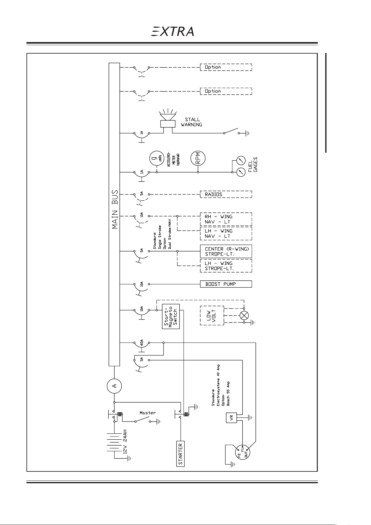
Section 7
Description and Operation of Aircraft and Systems
Standard Equipment shown only
Pilot´s Operating Handbook
EXTRA 200
7 - 14 Page Date: 20. April 2002
Page Date: 28. February 2006
Page 99

Pilot´s Operating Handbook
EXTRA 200
7.13 CABIN ENVIRONMENT CONTROL
A ventilation system in the canopy on the left side is provided for the supply of fresh air to
the cabin. Left and right at the rear seat are eyeball-type adjustable vents.
Description and Operation of Aircraft and Systems
Section 7
Page Date: 20. April 2002 7 - 15
Page 100

Section 7
Description and Operation of Aircraft and Systems
Pilot´s Operating Handbook
EXTRA 200
Left blank intentionally
7 - 16 Page Date: 20. April 2002
 Loading...