

Page 1
User Manual
High Voltage Oscilloscope Probe
MODEL TL625
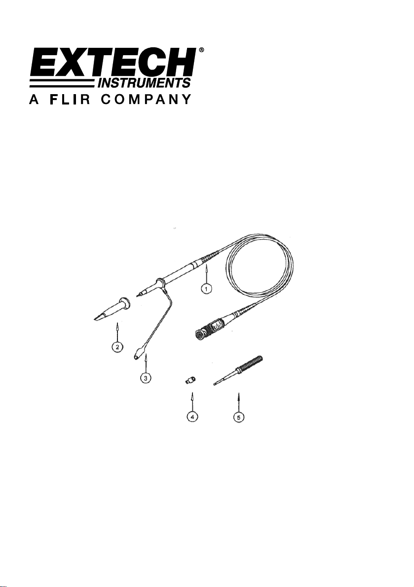
1 Probe Rod
2 Probe Tip
3 Ground Lead
4 Tip Locating Sleeve
5 Adjustment Tool
Page 2
Specifications
Attenuation 1:1000
Input Resistance 100MΩ
Input Capacitance X100:14.5pF to 17.5pF
Compensation Range 15pF to 35pF
System Bandwidth X100 DC to 100MHz
Maximum Working Input Voltage X100: <2000VDC + Peak AC
Cable Length 47” (120cm)
Weight 0.15lb (65g)
Operating Temperature 14F to 122F (-10C to 50C)
Storage Temperature -4F to 167F (-20C to 75C)
Humidity <85% RH
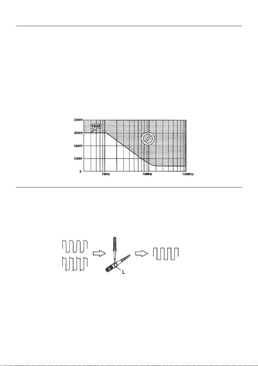
Maximum Working Voltage Derating Curve(VDC+PeakAC)
Low Frequency Probe Compensation
Before taking any measurements using the probe,firstcheckthecompensation and adjust it to match
the channel inputs. Most oscilloscopes have a square wave reference signal available at a terminal on
the front panel used to compensate the probe. Connect theprobetothesignalsource to display a
1kHz test signal on the oscilloscope.
Adjust the trimmer “L” until the signal displays a flat-top square wave.
2 TL625-EN-V1.0 4/12
Page 3
Manual del usuario
Sensor Osciloscopio de Alto
Voltaje
MODELO TL625
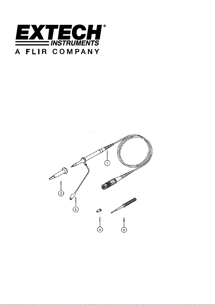
1 Varilla del sensor
2 Punta del sensor
3 Conector de tierra
4 Casquillo localizador de punta
5 Herramienta de ajuste
Page 4

Especificaciones
Atenuación 1:1000
Resistencia de entrada: 100MΩ
Capacitancia de entrada X100:14.5pF a 17.5pF
Escala de compensación 15pF a 35pF
Amplitud de banda del sistema X100 CD a 100MHz
Voltaje de entrada máximo de trabajo x100: <2000VCD + Pico CA
Longitud del cable 120cm (47”)
Peso 65 g (0.15 lb)
Temperatura de operación -10°C a 50°C (14°F a 122°F)
Temperatura de almacenamiento -20C a 75C (-4F a 167F)
Humedad <85% HR
Curva de reducción de voltaje de trabajo máximo (VCD + Pico CA)
Compensación de sensor por baja frecuencia
Antes de tomar cualquier medición con el sensor, primero verifique la compensación y ajuste para
igualar las entradas del canal. La mayoría de los osciloscopios tienen una señal de referencia de onda
cuadrada disponible en una terminal del panel frontal usada para compensar el sensor. Conecte el
sensor a la señal fuente para mostrar una señal de prueba de 1kHz en el osciloscopio.
Ajuste el potenciómetro "L" hasta que la señal muestre una parte superior plana de la curva cuadrada
2 TL625-SP-V1.0 4/12
 Loading...