


User's Guide
Visit us at www.TestEquipmentDepot.com
200A Mini Clamp + DMM
Model 380941
• Large 3 3/4 digit LCD display with 40 segment bargraph
• Continuity and Frequency Measurements
• One touch DCA zero adjust
• MIN/MAX and Data Hold functions
• 0.9” (23mm) Jaw diameter
99 Washington Street
Melrose, MA 02176
Fax 781-665-0780
TestEquipmentDepot.com
Introduction
Congratulations on your purchase of Extech’s DC/AC Clamp Meter. This professional meter,
with proper care, will provide years of safe reliable service.

Specifications
General Specifications
Display 3-3/4 (4000 count) Digit LCD with 40 segment bargraph
Functions ACA, DCA, ACV, DCV, Resistance, Frequency, Continuity
Polarity “-“ indicates negative polarity
Current sensor Hall effect sensor type
Overload indication Left blinking digit
DCA zero adjust One touch zero key
Display rate 2 readings/second (20 readings/second for bargraph)
Battery Two 1.5V AA batteries
Operating temp. 40F to 1220F (-100C to 500C)
Operating Humidity < 85% RH
Power consumption Approximately 10mA DC
Weight 8 oz. (225g) including battery
Dimensions 7 x 1.75 x 1.25” (178 x 45 x 32mm) (HWD)
Jaw opening 0.9” (23mm)
Standards IEC 1010 Category III 300V, Category II 600V
Range Specifications
Function Range Resolution. Accuracy Overload
DC Current
AC Current
DC Voltage 400V 0.1V ±(1.0% +2dgts) 1000VDC
Resistance
Frequency 100 to 10k 0.01Hz ±0.5% ±2dgts Sensitivity;
40A 10mA ±(1.0% +2dgts) 400A DC
0 to 150A 100mA ±(1.0% +2dgts) 400A DC
150 to 200A 100mA ±(2.2% +2dgts) 400A DC
50/60Hz 40 to 400Hz
40A 10mA ±(1.0% +3dgts) ±(1.5% +4dgts) 400A AC
0 to 150A 100mA ±(1.0% +3dgts) ±(1.5% +4dgts) 400A AC
150 to 200A 100mA ±(2.2% +3dgts) ±(2.5% ±4dgts) 400A AC
50/60Hz 40 to 400Hz AC Voltage
400V 0.1V ±(1.5% +2dgts) ±(2.0% +4dgts) 800V AC
40 to 400Ω
0.1 ±(1.0% +2dgts)
2
Beep <38Ω
2V, 0.1A AC
380941 Ver. 2.2 03/05
protect
600V AC
600V AC
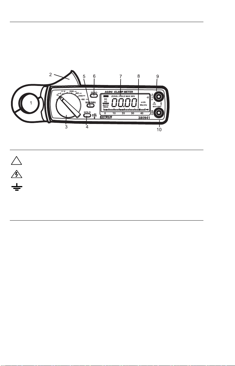
Front Panel Description
1. Current sense jaw
2. Measurement Trigger
3. Function switch
4. Data Hold key
5. Max Min key
6. One-touch DCA zero key
7. LCD Display
8. 40 segment bargraph display
9. Positive input terminal for V, HZ and Ω
10. COM terminal
International Symbols
Caution ! Refer to the explanation in this Manual
!
Caution ! Risk of electric shock
Earth (Ground)
Safety
This meter has been designed to be safe in use, but the operator must use caution in its
operation. The rules listed below should be carefully followed for safe operation.
1. NEVER apply voltage or current to the meter that exceeds the specified maximum:
2. USE EXTREME CAUTION when working with high voltages.
3. DO NOT measure voltage if the voltage on the "COM" input jack exceeds 500V above
earth ground.
4. NEVER connect the meter leads across a voltage source while the function switch is in
the current, resistance or diode mode. Doing so can damage the meter.
5. ALWAYS discharge filter capacitors in power supplies and disconnect the power when
making resistance or diode tests.
6. ALWAYS turn off the power and disconnect the test leads before opening the back to
replace the fuse or batteries.
7. NEVER operate the meter unless the back cover and the battery/fuse door are in pla ce
and fastened securely.
3
380941 Ver. 2.2 03/05
Test Equipment Depot - 800.517.8431 - 99 Washington Street Melrose, MA 02176
FAX 781.665.0780 - TestEquipmentDepot.com
Operation
AC Current Measurements
WARNING: To avoid electric shock, disconnect the test leads from the meter before
making current measurements.
1) Set the Function switch to the 40 or 200A AC range.
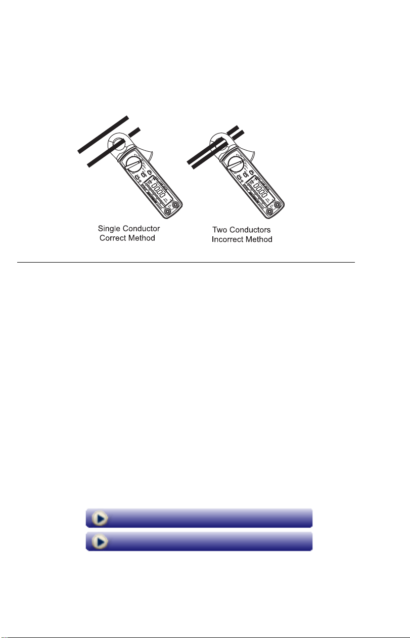
2) Press the jaw trigger and clamp around, fully enclosing a single conductor. Do not
allow a gap between the two halves of the jaw.
3) Read the ACA value on the LCD.
DC Current Measurements
WARNING: To avoid electric shock, disconnect the test leads from the meter before
making current measurements.
1) Set the Function switch to the 40 or 200A DC range.
2) Press the DCA zero key to null the meter display.
3) Press the Trigger to open the current sense Jaw.
4) Fully enclose the conductor to be measured. Do not allow a gap between the two
halves of the jaw.
5) Read the DCA value on the LCD.
AC Voltage Measurements
WARNING: To avoid electric shock or damage to the meter, do not make any voltage
measurements that exceed the maximum specified.
1) Set the Function switch to the VAC position.
2) Insert the test leads to the meter as follows: Red lead to “V,Hz,Ω” terminal; Black
lead to the COM input.
3) With the pointed end of the test le ads measure voltage. Remember that voltage
measurements are made in parallel with the device or circuit under test.
4) Read the ACV value on the LCD.
DC Voltage Measurements
WARNING: To avoid electric shock or damage to the meter, do not make any voltage
measurements that exceed the maximum specified.
1) Set the Function switch to the VDC position.
2) Insert the test leads to the meter as follows: Red lead to “V,Hz,Ω” terminal; Black
lead to the COM input.
3) With the pointed end of the test le ads measure voltage. Remember that voltage
measurements are made in parallel with the device or circuit under test.
4) Read the DCV value on the LCD.
Resistance and Continuity Measurements
WARNING: To avoid electric shock or damage to the meter, remove power to the circuit
under test and discharge all capacitors.
1) Set the Function switch to the Ω position.
2) Insert the test leads to the meter as follows: Red lead to “V,Hz,Ω” terminal; Black
lead to the COM input.
3) With the pointed end of the test le ads measure resistance. Remember that
resistance measurements are made in parallel with the device or circuit under test.
4) Read the resistance value on the LCD.
5) If the resistance is less than 40Ω, the continuity beeper will sound.
4
380941 Ver. 2.2 03/05
Frequency Measurements
1) Ensure that at least 0.1A AC is detectable with an ACA measurement before
measuring Frequency.
2) Set the Function switch to the Hz position.
3) Press the Trigger to open the Jaw and fully enclose the conductor to be measured. If
line frequency is being measured, enclose only one line of the source (ensure first
that there is current present).
4) Read the Frequency measurement on the LCD in Hz.
Special Features
Relative Measurements
1) Press the Zero key and the present measurement will Zero.
2) All subsequent measurements are displayed with respect to the zeroed reading. For
example, if a 20A reading is zeroed and a 30A reading is subsequently measured,
the LCD will display 10A.
3) To return to normal operation, press and hold the zero key for 2 seconds.
4) Note that Relative mode is not available if MIN/MAX mode is enabled.
Data Hold
To freeze the current reading on the LCD, press the Data Hold key. To release the Data
Hold function and return the meter to normal operation, press the Data Hold key again.
MIN/MAX Readings
Pressing the MIN/MAX key allows the meter to display ONLY the highest and the lowest
readings encountered. Press the MIN/MAX key once to view the minimum reading,
press it again to view the maximum reading. Note that the meter will only change its
displayed reading when a measurement is taken higher than the previous MAX or lower
than the previous MIN readings. The HOLD display icon (along with the MIN or MAX
icon) will appear on the LCD in MIN/MAX mode Pressing the MIN/MAX key a 3
returns the meter to normal operation.
rd
time
Back to the Extech 380941 Product Page
Visit us at www.TestEquipmentDepot.com
5
380941 Ver. 2.2 03/05
Test Equipment Depot - 800.517.8431 - 99 Washington Street Melrose, MA 02176
FAX 781.665.0780 - TestEquipmentDepot.com
 Loading...