


Introduction
Congratulations on your purchase of Extech’s Insulation Tester/Megohmmeter. The Model 380363
provides three test ranges plus continuity and AC/DC voltage measurement. Manual datalogging
stores up to 9 data sets. This professional meter, with proper care, will provide years of reliable
service.
Safety
1. Circuits under test must be de-energized and isolated before connections are made (except for
voltage measurements).
2.
Circuit connections must not be touched during a test. Use extreme caution when
bare conductors
shock.
3.
Use caution when working near voltages above 60VDC or 30VACrm
4.
After insulation tests, capacitors
Test leads (including alligator clips) must be in good working order, clean and withou
5.
or cracked insulation.
When servicing, use only specified replacement pa
6.
Intern
ational Safety Symbols
Caution, refer to this manual before using this meter
Dangerous Voltages
and bus bars. Accidental contact with conductors
must be discharged.
rts.
could result in electrical
s.
working near
t broken
Meter is protected throughout by double or reinforced insulation
2
Model 380363-EU-EN-V-3.1-1/12
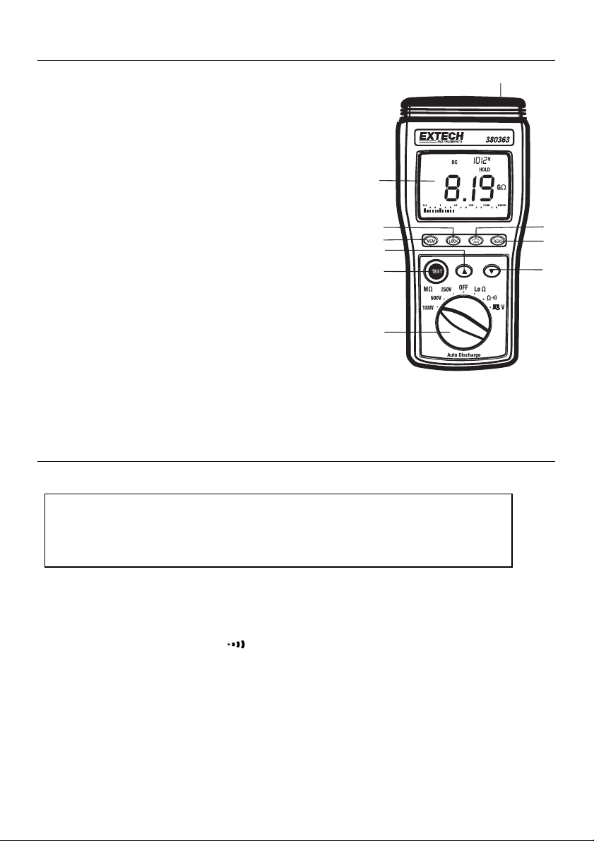
Meter Description
10
1. LCD
2. LOCK
3.
4.
5. TEST button
6. Rotary
7.
8.
9. ZERO
10. Input terminals
The tilt stand and
of the instrument
Display
but
ton
MEMORY contro
UP arrow key
itch
sw
DOWN arro
READ memory bu
w key
adjust butt
battery compartment are located at the rear
l button
tton
on
1
2
3
4
5
6
Operation
Connecting Test Leads
Warning
Ensure that the circuit under test does not include components that can be damaged by 1000VDC; such
devices include power factor correction capacitors, low voltage mineral insulated cables, electronic light
dimmers, and ballasts/starters for fluorescent lamps.
9
8
7
For all measure
the COM input terminal.
Test Lead Check
1. Set the rotary switch to the Ω range.
2.
Touch the test lead tips together.
3.
Resistance should read less than 0.5Ω and the au
With the leads not touching, the display should read OL indicating over-rang
4.
Readings displayed other than the readings described above are evidence of a prob
5.
the test leads must be replaced be
to equipment an
the instrument fo
ments connect the red test lead to the VΩ input terminal and the black test lead to
dio tone should sound.
fore using the meter. Failure to do
d electrical shock. If replacing the test leads does not solve the problem, return
r repair.
3
e.
lem and
so could result in damage
Model 380363-EU-EN-V-3.1-1/12

Insulation Resistance Measurements (Megohmmeter Tests)
Warning: Do not perform Insulation Resistance measurements if AC Voltage is present on the device
under test.
1. Connect the red test lead to the VΩ input terminal; black lead to the COM terminal.
2. Set the function switch to the desired MΩ
Connect the tips of the test leads to the equipment under test. If ther
3.
w
ill be displayed. A repetitive beep and the flashing high voltage symbol
the voltage is over 30V.
4.
The display will show “----“ until the TEST button is pushed. Press and hold the TEST
The uppe
If the displa
5.
Keep the test leads connected to the equipment under test and release the TEST bu
circuit w
completely
r right display shows the test voltage applied. The main display shows the re
y reads OL, the measurement is beyond the range of th
ill discharge through the meter. Keep the te
discharged and the upper right display show
test voltage position.
st leads connected until the circuit is
s 0 volts.
e is a voltage present, it
will be displayed if
e instrument.
button.
sistance.
tton. The
Test Lock Function
For hands-free operation, use the TEST LOCK feature.
1.
With the test leads connected to the equipment under test, press the LOCK key to en
LO
CK mode. The LOCK icon “ “ will appear on the display.
2.
Press the TEST key to start the test. A beeper will sound every
meter is in Lock mode.
Press LOCK or T
3.
EST to disable the Lock function and end the test.
2 seconds to indicate that the
ter the
Notes on IR (Megohmeter) testing:
1. The maximum measurement range for the 380363 is 10G. Frequently, insulation resistance
w
ill exceed this value and the meter will show the overload display sy
the insulation under test is good.
2.
If the device being tested is highly capacitive, the display will
value over time. Allow the reading to stabilize before ending a test.
mbol OL, indicating that
indicate an increasing resistance
Manual Data Store and Read Mode
To Clear Memory
Turn the meter of
1.
Press and hold down the MEM key, and turn the me
2.
The display will show “MEM”, "X",
3.
4. Press
5.
Enterin
1.
2.
3.
Readi
1.
2. Use
3.
"” to select "yes" to erase or "no" to leave.
If "yes" was selected, press "MEM" to erase the memory
g data into memory
Press the MEM key to enter the displayed data into memory
The display will show “MEM” and the memory address number in the upper left hand
Total memory size is 9 sets.
When the memory is full, the LCD will show "MEM
ng memory da
Press the READ key to enter Read Mode. The display will show the “READ” icon a
memor
y address number in the upper left hand co
the and arrow keys to scroll through the stored readings.
Press the READ key again to exit
f.
ter on.
"CLr" and "no".
.
.
F".
ta
rner.
this mode.
4
corner.
nd the
Model 380363-EU-EN-V-3.1-1/12


Using the LOCK Function to measure resistance
The Lock function can be used to make several resistance measurements in succession without the
need to push and hold the TEST key for each measurement.
1.
Press the LOCK key to enter the LOCK mode, and then press the TEST key.
2.
Zero out the test
3.
Connect the prob
Press the LOCK key to disable th
4.
Note: The
before connecting the test leads or the fuse may blow.
meter cannot indicate if the circuit is live in this mode. Ensure that the circuit is de-energized
lead resistance.
es to the test locations in succession.
e lock function.
Auto Power Off
To conserve battery life, the meter will automatically turn off after 15 minutes of non-use. To turn the
meter back on, turn the rotary switch to OFF, then to the desired function.
Analog Bar Graph
The analog bar graph displays resistance on a logarithmic scale and voltage on a linear scale. The
value always tracks the main display.
Maintenance
Battery Replacement
When the low battery symbol appears (BT) on the LCD the six 1.5V ‘AA’ batteries must be replaced.
1.
Turn the meter off and remove the
2.
Remove the four (4) Phillips head screws on the rear of the mete
3.
Remove the mete
4.
Replace the batteries observing polarity
5.
Affix the rear cover and secure the rear screw
Y
ou, as the end user, are legally bound (Battery ordinance) to return all used batteries
and accumulators; disposal in the household garbage is prohibited!
You can hand over your used batteries / accumulators at collection points in your
community or wherever batteries / accumulators are sold!
Disposal: Follow the valid legal stipulations in respect of the disposal of the device at the
end of its lifecycle
r’s rear cover
test leads
r
s
Fuse Replacement
If the meter turns ON but does not measure correctly, check the internal fuse.
1.
Turn the meter off and remove the
2.
Remove the four (4) Phillips head screws on the rear of the mete
3.
Remove the mete
4.
Check and replace the fuse if necessary (0.5A / 60
5.
Affix the rear cover and secure the rear screw
r’s rear cover
test leads
r
0V fast blow)
s
Cleaning
Periodically wipe the case with a dry cloth. Do not use solvents or abrasives to clean this instrument.
6
Model 380363-EU-EN-V-3.1-1/12


Testing DC Motors
1. Disconnect the motor from the line.
2. To test the brush rigging, field coils and armature, connect one meter lead to the gro
motor housing a
If the resistance measurement indicates a weakness, raise the brus
3.
and separatel
connected to the
applies to DC Generators.
nd the other lead to the brush on t
y test the armature, field coils and brush rigging (one at a time). Leave
grounded motor housing while testing the motor components. This al
he commutator.
hes off of the commutator
Testing Cables
1. Disconnect the cable under test from the line.
2. Disconnect the opposite end of the cable to avoid errors as a result of leakage from
equipment.
Check each conductor to ground and/or lead sheath by connecting one meter lead to
3.
and/or lead shea
4.
Check insulation resistance between conductors by connecting meter l
pairs. Refer to
to the grou
meter. Th
th and the other meter lead to eac
diagram. In the diagram, note that the 3-conductor cable has two wire
nd shield. This two-wire/shield
e remaining conductor is connected to the other side of the
connection is then connected to one side of the
h of the conductors in turn.
eads to conductors in
meter.
unded
one lead
so
other
ground
s shorted
8
Model 380363-EU-EN-V-3.1-1/12

Specifications
General specifications
Display 3-3/4 digit (4000
Sampling rate 1 reading per second
Test ranges
AC/DC Voltage range 999V
Resistance range
Lo Resistance range
Over range indicator ‘OL’ displayed when measurement exceeds range
Zero adjust Automatic
Memory Nine (9) data records
Low battery indicator ‘BT’ symbol displayed when battery voltage is low
Power source Six (6) 1.5 ‘AA’ batteries
Power consumption 20 to 95mA (depending upon function)
Fuse protection 0.5A / 600V fast blow fuse
Operating conditions 0 to 50oC (32 to 122oF); 80% RH
Dimensions 235 x 116 x 54mm (9.3 x 4.6 x 2.1”)
Weight 520g (1.15 lbs)
Safety ratings Pollution degree 2; indoor use; CE marked;
Category Rating CAT III-1000V
Resistance: 4MΩ, 40MΩ, 400MΩ, 4000MΩ, 10GΩ
Test Voltages: 250V, 500V, 1000V
9999Ω
40Ω
Meets IEC 61010-1 and IEC 61557 standards
count) LCD
9
Model 380363-EU-EN-V-3.1-1/12

Range Specifications
MEGOHMMETER RANGES
Range Test Voltages Resolution Accuracy
4MΩ 0.001MΩ
40MΩ 0.01MΩ
400MΩ 0.1MΩ
4000MΩ 1MΩ
10GΩ
250V (+30% ~ -0%)
500V (+30% ~ -0%)
1000V (+30% ~ -0%)
00.01GΩ
3%+5 (<1000M)
5%+5 (>1000M)
(% reading + digits at
o
C ± 5oC < 80% RH)
23
Analog Bar Graph 0 to 10G
Nominal Current
Circuit Protection
AC
VOLTAGE (40Hz-500Hz)
Range Res.
≧ 1mA
Test inh bited if input ≧ 30V AC or DC
Accuracy Input impedanc
e
Overlo
Protection
999VAC 1V ±2% + 2d
9MΩ
1000Vrms
ad
DC VOLTA
GE
Range Res. Accuracy Input impedance Overload
999VDC 1V ±1% + 2d
RESISTA
NCE & CONTINUITY
9MΩ
Range Res. Accuracy Max. open circuit
Volt
Resistance: 999.9Ω 0.1Ω
Continuity
LOW RESIS
TANCE Ω
±1% + 3d 3V 1000Vrms
100Ω ± 80Ω)
Range Res. Accuracy Max. open circuit
Volt
40Ω 0.01Ω
uipment Depo
Test Eq
±2% + 2d 6V >30V AC/DC
t - 800.517.8431 - 5 Commonwealth Ave, MA 01801 -
TestEquipmentDepot.com
Protection
1000Vrms
Overload
Protect.
Overload
Protection
10
Model 380363-EU-EN-V-3.1-1/12
 Loading...