

Page 1
99 Washington Street
Melrose, MA 02176
Phone 781-665-1400
Toll Free 1-800-517-8431
User Guide
Visit us at www.TestEquipmentDepot.com
Back to the Extech 380360 Product Page
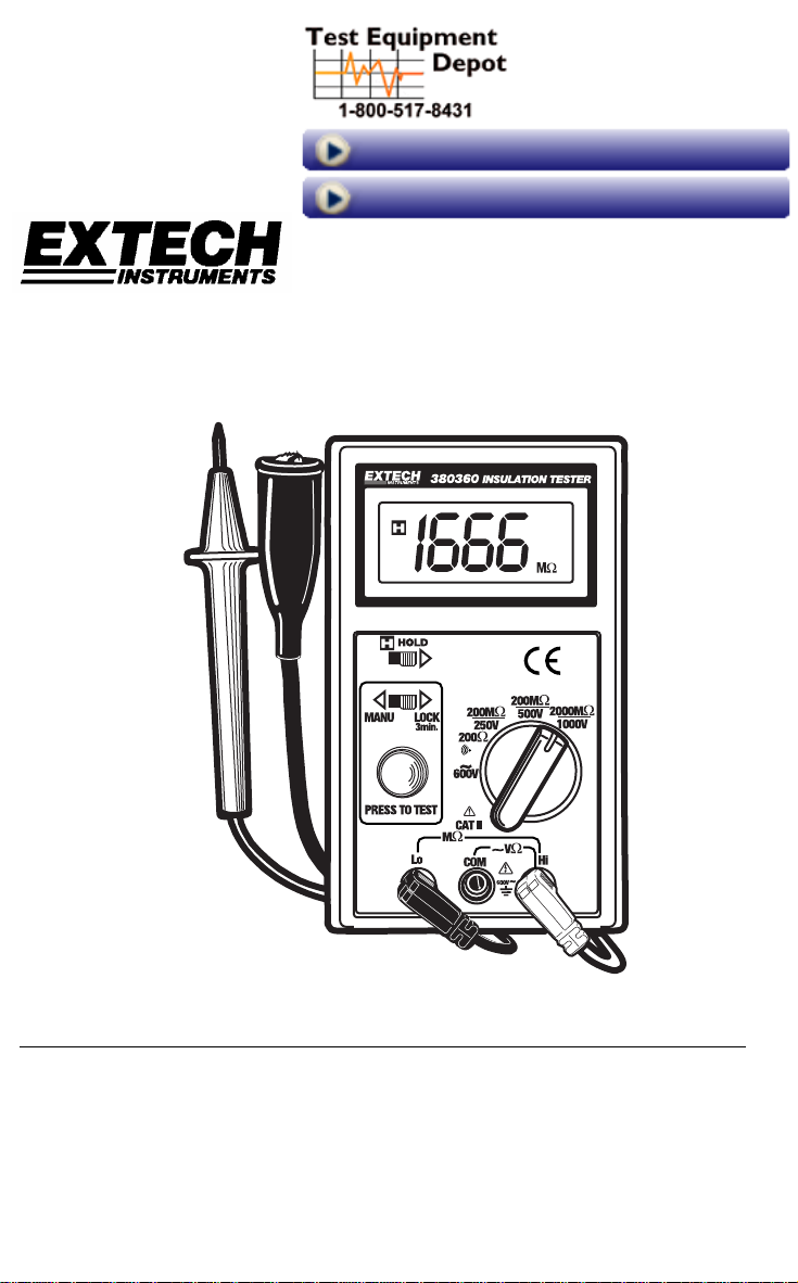
Model 380360
Insulation Tester / Megohmmeter
Introduction
Congratulations on your purchase of Extech’s Insulation Tester/Megohmmeter. The Model
380360 provides three test ranges plus continuity and an AC voltage test. A handy 3-minute
test lock feature and a data hold switch are also included. This professional meter, with
proper care, will provide years of reliable service.
Test Equipment Depot, 99 Washington Street, Melrose, MA 02176
781.665.1400 | 800.517.8431 | Fax: 781.665.0780
Page 2
Safety
1. Circuits under test must be de-energized and isolated before connections are made
(except for voltage measurements).
2. Circuit connections must not be touched during a test. Use extreme caution when
working near bare conductors and bus bars. Accidental contact with conductors could
result in electrical shock.
3. Use caution when working near voltages above 60VDC or 30VACrms.
4. After insulation tests, capacitors must be discharged.
5. Test leads (including alligator clips) must be in good working order, clean and without
broken or cracked insulation.
6. When servicing, use only specified replacement parts.
International Safety Symbols
Caution, refer to this manual before using this meter
Dangerous Voltages
Meter is protected throughout by double or reinforced insulation
Specifications
General specifications
Display 0.65” 3-1/2 digit (2000 count) LCD
Sampling rate 2.5 readings per second
Test ranges
AC Voltage range 600VAC
Resistance range
Over range indicator ‘1____’ displayed
Zero adjust Automatic
Low battery indicator ‘BT’ symbol displayed when battery voltage is low
Power source Six (6) 1.5 ‘AA’ batteries
Power consumption 20 to 95mA (depending upon function)
Operating conditions 32 to 104oF (0 to 40oC); 80% RH
Dimensions 6.5 x 3.9 x 2.2” (165 x 100 x 57mm)
Weight 1.1 lbs (500g)
2000MΩ/1000VDC, 200MΩ/500VDC, 200MΩ/250VDC
200Ω
2
Model 380360 Version 1.7 September 2003
Page 3
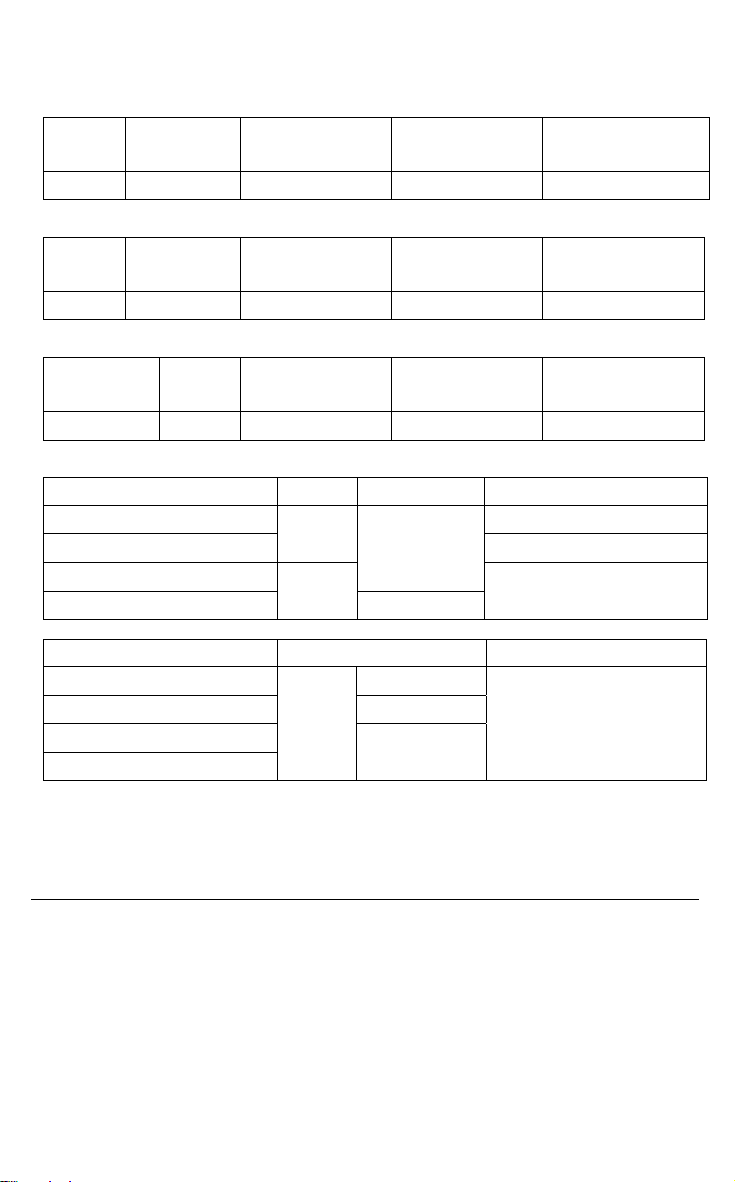
Range Specifications
Accuracies are specified as % reading + digits at 23
o
C < 80% RH
RESISTANCE
Range Res. Accuracy Max. open
circuit Volt
200Ω 0.1 Ω
±1% + 2d 3.3V 500Vrms
Overload
Protect.
CONTINUITY
Range Res. Audible tone Max. open
circuit Volt
200Ω 0.1Ω < 100Ω
3.3V 500Vrms
Overload
Protect.
AC VOLTAGE
Range Res. Accuracy Input impedance Overload
Protect.
600VAC 1V ±0.8% + 3d
10MΩ
750Vrms
MEGOHMMETER RANGES
Range Res. Accuracy Terminal voltage
200MΩ / 250VDC
200MΩ / 500VDC
0 to 1000MΩ / 1000VDC
1000 to 2000MΩ / 1000VDC
0.1MΩ
1MΩ
±3% + 5d
±5% + 5d
250V + 10% ~ -0%
500V + 10% ~ -0%
1000V + 10% ~ -0%
Range Test Current / Load Short circuit Current
200MΩ / 250VDC 250KΩ
200MΩ / 500VDC 500KΩ
0 to 1000MΩ / 1000VDC
1000 to 2000MΩ / 1000VDC
1mA
< 1.5mA
1MΩ
Application Note for Large Installations
In large wiring installations where the insulation of outlets is being tested, more than one
insulation resistance measurement may have to be made to take into account parallel
resistances. Divide large systems into subgroups and test subgroups individually. Also, in
large installations, the capacitance of the insulation will be high, thereby taking longer to
charge when being tested. Care must be taken not to finish a measurement until the
insulation capacitance is fully charged (a steady, stable reading is an indication that this is
the case). Be careful not to turn the range switch while the test button is pressed.
3
Model 380360 Version 1.7 September 2003
Page 4

Meter Description
1. LCD Display
9
10
2. Rotary function switch
3. Data hold switch
4. Test button
5. Manual / Lock select switch
6. HI input terminal
7. COM input terminal
8. LO input terminal
9. Positive test lead
10. Negative test lead
4 8 7
Warning
Ensure that the circuit under test does not include components that can be damaged by 1000VDC; such
devices include power factor correction capacitors, low voltage mineral insulated cables, electronic light
dimmers, and ballasts/starters for fluorescent lamps.
Operation
1
3
5
2
6
Connecting Test Leads
For the MΩ range, connect the red test lead to the HI input terminal and the black test lead
to the LO input terminal. For the 200Ω and 600VAC functions, connect the red test lead to
the HI (right) input jack and the black lead to the COM (center) jack.
Test Lead Check
1. Connect the red test lead to the HI input terminal; black lead to the COM terminal.
2. Set the rotary switch to the 200Ω
3. Set the HOLD switch to the left off position and the
MANU/LOCK switch to the MANUAL position.
4. Touch the test lead tips together.
5. Press the red TEST button.
6. Resistance should read less than 1Ω and the audio tone
should sound.
7. With the leads not touching, the display should read 1__
indicating over-range.
8. Readings displayed other than the readings described above are indicative of a test
lead problem. The test leads must be replaced before using the meter. Failure to do
so could result in damage to equipment and electrical shock.
range.
4
Model 380360 Version 1.7 September 2003
Page 5

Insulation Resistance Measurements (Megohmmeter Tests)
Warning: Do not perform Insulation Resistance measurements if AC Voltage is present on the
device under test.
1. Connect the red test lead to the HI input terminal; black lead to the LO terminal.
2. Set the HOLD switch to the left off position and the MANU/LOCK switch to the
MANUAL position.
3. Set the rotary switch to the desired test voltage (250V, 500V,
or 1000V).
4. Connect the tips of the test leads to the equipment under test.
5. Press and hold the TEST button. Release the test button to
stop the test.
6. Read the measurement value on the LCD display.
3-Minute Test Lock
For hands-free operation, use the TEST LOCK feature.
1. Connect the red test lead to the HI input terminal; black lead
to the LO terminal
2. Set the rotary switch to the desired voltage test position
(250V, 500V, or 1000V).
3. Connect the tips of the test leads to the equipment under test.
4. Set the MANU/LOCK switch to the LOCK position.
5. Press and release the red TEST button. A 3-minute continuous test will begin. The
red TEST button can be pressed at any time to end the test. If the TEST button is not
pressed, the meter automatically stops the test after 3 minutes.
Notes on IR (Megohmeter) testing:
1. The maximum measurement range for the 380360 is 2000MΩ (2GΩ). Frequently,
insulation resistance will exceed this value. When this happens, the display will
indicate 1
is good.
MΩ, meaning the resistance is very high and the insulation being tested
2. If the device being tested is highly capacitive, the display will indicate an increasing
resistance value over time. Always wait until the reading has stabilized before
recording the value.
5
Model 380360 Version 1.7 September 2003
Page 6

Low Resistance and Audible Continuity Tests
Do not run this test unless ACV = 0. Do not use this mode to check diodes.
1. Set the Rotary switch to the 200Ω position.
2. Connect the red test lead to the HI input terminal; black lead to the COM terminal.
3. Connect the tips of the test leads to both ends of the circuit under test.
4. Press the red TEST button and read the resistance on the LCD.
5. When the resistance of a circuit is less than approx. 100Ω the audible tone will sound.
WARNING
AC Voltage Tests
1. Set the Rotary switch to the red 600V position.
2. Connect the red test lead to the HI terminal and the black test lead to the COM
terminal.
3. Connect the other end of the test leads to the circuit under test.
4. Read the voltage value on the LCD.
Data Hold Function
The Data Hold function freezes the displayed reading. Move the HOLD switch to the
rightmost position to freeze the displayed reading. The ‘H’ will appear on left side of the
display when the meter is in the Data Hold mode. Move the switch to the left position to
exit the Data Hold mode (the ‘H’ indicator will switch off).
Maintenance
Battery Replacement
When the low battery symbol appears (BT) on the LCD the six 1.5V ‘AA’ batteries must be
replaced.
1. Turn the meter is off and remove the test leads
2. Remove the Phillips head screw on the rear of the meter
3. Remove the battery compartment cover
4. Replace the batteries observing polarity
5. Affix the rear cover and secure the rear screw
Cleaning
Periodically wipe the case with a dry cloth. Do not use solvents or abrasives to clean this
instrument.
6
Model 380360 Version 1.7 September 2003
Page 7

Applications
Measuring Power Tools and Small Appliances
This section applies to any device under
test that uses a line cord. For double
insulated power tools, the meter’s leads
should be connected to the device’s
housing (chuck, blade, etc.) and the ground
of the power cord. Refer to the diagram.
Testing AC Motors
Disconnect the motor from the line by disconnecting the wires from the motor terminals or
opening the mains switch.
If the mains switch is opened, and the motor also has a motor-starter, then the starter must
be held in the ON position. With the mains switch opened, the measured resistance will
include the resistance of the motor wire and all other components between the motor and
the main switch. If a weakness is indicated, the motor and other components should be
checked individually. If the motor is disconnected at the motor terminals, connect one
meter lead to the grounded motor housing and the other lead to one of the motor leads.
Refer to diagram at below.
Motor
Starter
GND
LO HI
meter test leads
Testing DC Motors
1. Disconnect the motor from the line.
2. To test the brush rigging, field coils and armature, connect one meter lead to the
grounded motor housing and the other lead to the brush on the commutator.
3. If the resistance measurement indicates a weakness, raise the brushes off of the
commutator and separately test the armature, field coils and brush rigging (one at a
time). Leave one lead connected to the grounded motor housing while testing the
motor components. This also applies to DC Generators.
Testing Cables
1. Disconnect the cable under test from the line.
2. Disconnect the opposite end of the cable to avoid errors as a result of leakage from
other equipment.
3. Check each conductor to ground and/or lead sheath
by connecting one meter lead to ground and/or lead
sheath and the other meter lead to each of the
conductors in turn.
4. Check insulation resistance between conductors by
connecting meter leads to conductors in pairs. Refer to diagram at right. In the
diagram, note that the 3-conductor cable has two wires shorted to the ground shield.
This two-wire/shield connection is then connected to one side of the meter. The
remaining conductor is connected to the other side of the meter.
Appliance
HI LO
Meter test leads
Mains
Switch
Notes:
1. The STARTER must be in the ON position during
the test.
2. The motor-to-meter connection must be made to
the motor housing (ground).
3. The meter-to-main switch connection must be to the
motor side of the main switch as shown.
LINE
LO HI
Test leads
Test Equipment Depot, 99 Washington Street, Melrose, MA 02176
781.665.1400 | 800.517.8431 | Fax: 781.665.0780
 Loading...