

Page 1
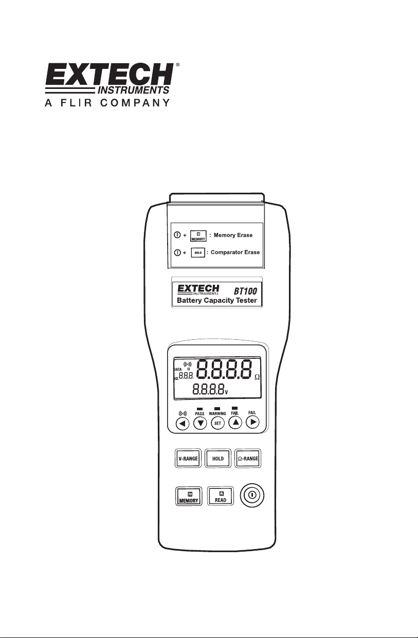
User's Guide
Battery Capacity Tester
Model BT100
Page 2

Introduction
The Battery Tester is designed for measuring the internal resistance and output voltage of
batteries including lead storage cell, nickel-cadmium battery, lithium-ion battery and nickelmetal hydride battery.
AC four-terminal method to eliminates lead resistances and contact resistances and
yield the most accurate results.
1kHz test current with up to 10µΩ resistance resolution.
Dual display simultaneously indicates the internal resistance and voltage of the
battery.
Comparator function with storage of up to 99 sets of resistance and voltage values for
battery deterioration characterization.
Pin type and alligator type 4-terminal Kelvin leads for quick and accurate resistance
measurements.
Memory capacity to store up to 999 manually stored data points or up to 9600 points
stored using interval datalogging.
RS232 PC port and Windows compatible software.
Warranty
EXTECH INSTRUMENTS CORPORATION warrants the basic instrument to be free of defects in parts and
workmanship for one year from date of shipment (a six month limited warranty applies on sensors and cables). If it
should become necessary to return the instrument for service during or beyond the warranty period, contact the
Customer Service Department at (781) 890-7440 EXTENSION 210 for authorization or visit www.extech.com
more information. A Return Authorization (RA) number must be issued before any product is returned to
Extech. The sender is responsible for shipping charges, freight, insurance and proper packaging to prevent
damage in transit. This warranty does not apply to defects resulting from action of the user such as misuse,
improper wiring, operation outside of specification, improper maintenance or repair, or unauthorized modification.
Extech specifically disclaims any implied warranties or merchantability or fitness for a specific purpose and will not
be liable for any direct, indirect, incidental or consequential damages. Extech's total liability is limited to repair or
replacement of the product. The warranty set forth above is inclusive and no other warranty, whether written or
oral, is expressed or implied.
for
2
Version 2.1 7/09
Page 3
Specifications
Measuring method: Resistance (AC four-terminal method).
A/D conversion: Dual slope method.
Display: Dual display LCD and LEDs (comparator output).
Sampling rate: 1 set (resistance & voltage measurements)/second.
Open-Circuit terminal voltage: 3.5Vpp max.
Input over range: “OL” display.
Low battery detection:
Test current fault detection: “- - - -” display.
Auto power off: After approximately 30 minutes.
Zero (Relative) function: Circuit offset voltage is displayed as 0V.
Hold function: Display is held.
Beeper function: Audible output for warning and fail results (can be
Comparator settings: Resistance High and Low limits and voltage
Number of comparator settings: 99 sets.
Comparator output: LEDs for pass (green), warning (yellow) and fail
Resistance
Voltage
Lo Warning Warning Fail
Hi PASS Warning Fail
display.
turned on and off).
threshhold point.
(red) results, audible tone for warning and fail.
Lo IN Hi
Manual Data logging: 999 sets.
Continuous Data logging: 9600 sets.
Operating environment: 32 to 104°F (0
Storage environment: 14 to 122°F (-10
Power source: Six AA size 1.5V batteries. (AC adaptor (output
9VDC) is optional)
Maximum power consumption: 1.0VA
Continuous operating time: 7 hours approx.
Maximum altitude value usable: 2000m or less.
Size: 9.8x3.9x1.7” (250×100×45mm)
Weight: 1.1 lbs (500g) approx. (including batteries)
Accessories: Test Leads, Instruction Manual, Batteries.
Option: AC adaptor (9V DC output).
3
°
to 40
°
°C)
80%RH (non-condensing)
to 50
°C)
80%RH (non-condensing)
Version 2.1 7/09
Page 4
Electrical Specifications
Conditions to guarantee accuracy:
Temperature: 23
Humidity: 80%RH or less (non-condensing).
Zero adjustment: After zero adjustment for each range.
Resistance measurement
Temperature coefficient: (
Measuring current frequency: 1KHz
Measuring burden voltage:
Range Resolution Measurement current Accuracy
40mΩ 10µΩ 37.5mA approx.
°C ± 5°
±
0.1% rdg ± 0.5digits)/°C
±
10%
1.5mVAC
400mΩ 100µΩ 3.75mA approx.
4Ω 1mΩ 375µA approx.
40Ω 10mΩ 37.5µA approx.
Voltage Measurement
Temperature coefficient (
Range Resolution Accuracy
4V 1mV
40V 10mV
Maximum Input Voltage: 50VDC maximum, No AC voltage input, , 60VDC and AC
maximum between input terminals and ground.
Do not exceed the maximum permissible input voltage to the measurement terminal. This
could result in injury or damage to the unit.
±
0.1%rdg±0.5digits)/
DANGER
°C
±
(0.1% reading ± 6digits)
±
(1% reading ± 10digits)
4
Version 2.1 7/09
Page 5
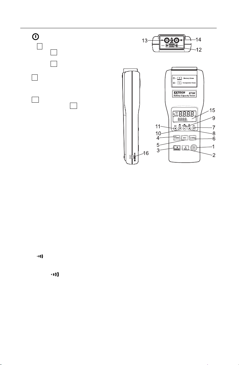
Meter Description
1.
2. R READ button:
3. M MEMORY button:
4. V-RANGE button: Select the voltage
5. HOLD button:
6. Ω - RANGE button: Select the resistance range. (40mΩ, 400mΩ, 4Ω, 40Ω)
7. REL button:
8. button : Press button to increase the displayed value.
9. SET button:
10. button: Press button to decrease the displayed value.
11.
12. RS-232 connector: PC interface connector.
13. – Input jack: For connecting with the black test lead plug.
14. + Input jack: For connecting with the red test lead plug.
15. LCD display
16. AC adaptor input
Power button: Power on /off
Press R button to show the manual
logged readings.
Press R READ button again to stop
reading.
Under the manual logging mode, the
tester stores each single set of logged
reading to the memory by pressing
M MEMORY button.
Press and hold M MEMORY button
for 2 seconds to enter continuous
logging mode. Press again to stop
logging.
range. (4V, 40V)
Press HOLD button to freeze or unfreeze
the displayed reading.
Press and hold HOLD button for 2
seconds to enter the interval time setting
mode for continuous data logging.
Press button to move the cursor to the right.
Press REL (Relative) button to zero the reading.
Press SET button to switch the comparator mode on or off.
Press and hold the SET button for 2 seconds to enter the comparator-setting mode.
Press again to store the setting in memory.
Button:
Press button to move the cursor to the left.
Press
button to turn the beeper on or off.
5
Version 2.1 7/09
Page 6

Display Description
1. Measured resistance reading (High or Low limit of resistance on the comparator
settings)
2. Measured voltage reading (High or Low limit of voltage on the comparator settings).
3. The assigned number of comparator: 99 sets
4. The location for the manual logged data.
5. Symbols:
mΩ: Milliohm (resistance).
V: Voltage.
HOLD : Hold function.
COMP : Comparator function enabled.
: Low-Battery
:
Beeper enabled
DATA R : Manual datalogging enabled.
M : Continuous datalogging enabled (Flashes when data is stored).
INTV: Interval time settings of continuous datalogging function. (1~255
COMP.SET : Comparator settings.
HIGH: High limit setting of the comparator resistance & voltage.
LOW: Low limit setting of the comparator resistance.
LED Display Indicators
PASS (green LED): Battery complies with the high limit of comparator.
WARNING (yellow LED) Battery is beginning to deteriorate.
FAIL (red LED): Battery has failed.
These indications will appear when the High and Low comparator limits for internal resistance and
the comparator threshold value for voltage are all set.
seconds).
6
Version 2.1 7/09
Page 7

Basic Operation
Preparation
The following safety information must be observed to ensure maximum personal safety
during the operation of this tester.
To avoid electric shock when replacing the batteries first disconnect the leads from the
object to be measured.
Check the battery polarity carefully when inserting the batteries.
Be sure to dispose of used batteries properly.
1. Remove the battery cover.
2. Insert the batteries into the battery compartment.
WARNING
Do not attempt to measure DC voltage exceeding 50V. Do not attempt to
measure AC voltages. This could result in injury or damage to the unit.
Do not attempt to measure the voltage of a generator. This would result in an
AC voltage being applied to the voltage generating output terminals, which is
dangerous.
After measuring a high voltage battery, before continuing to measure a low
voltage battery first short the measurement leads together. This will discharge
the DC-elimination capacitor which is connected across the leads. Otherwise
an excess voltage may be applied to the low voltage battery, which is
dangerous.
Test Leads
Two sets of test leads are supplied with the meter. Both sets provide 4 terminal Kelvin
connections which eliminates lead resistance and probe contact resistance from the
measurement. Use of either the alligator or press-probe is determined by the measurement
application.
7
Version 2.1 7/09
Page 8

Operation
Connect the red test lead to the “+” jack and the black test lead to the “-” jack.
1. Press Power
2. Connect the red test probe to the positive battery terminal, and the black test probe to
the negative battery terminal.
3. Use the V-RANGE and Ω-RANGE buttons to select the desired voltage and resistance
ranges.
4. Read the battery internal resistance and DC voltage directly from the display.
Note : When the measured DC voltage or battery internal resistance value is over range,
“OL” is displayed.
When the AC test current faults, “- - - -” will be displayed.
REL Zero Adjust
The REL function zeros the selected range of resistance and voltage. The reading
displayed when the REL button is pressed will be taken as zero and will be used to
calibrate subsequent measurements.
1. Short the 4 tips of red and black test leads probe terminals.
2. Press REL button. The display shows R , then the resistance and voltage value is zero,
connect the test leads probe to the battery to be tested.
3. The zero adjustment is valid only for the currently selected range, as long as the power
remains on.
button to turn on the tester.
8
Version 2.1 7/09
Page 9

Comparator (99 sets)
The comparator function compares the measured values with preset High and Low limit
values for internal resistance and voltage level, and determines the range that the
measurement should fall into. Then, according to the following conditions, lights the
corresponding LED, and sounds a beeper under the WARNING and FAIL cases.
Comparator Settings
1. Press and hold the “SET” button for 2 seconds, the display will show COMP.SET
indicating the comparator mode is enabled.
2. Use the or button to change the comparator number from 01 up to 99.
3. Use the V-RANGE or Ω-RANGE button to set the desired voltage and resistance
measured range.
4. Press button one time, LOW and the left two digits of the low limit resistance
flashing. (Use the & buttons to select the desired value.)
5. Press button one time, the right two digits of the low limit resistance
(Use the and buttons to select the desired value.)
6. Press button one time, HIGH and the left two digits of the high limit resistance
flashing. (Use the and buttons to select the desired value.)
7. Press button one time, the right two digits of the high limit resistance
(Use the and buttons to select the desired value.)
8. Press button one time, the left two digits of the threshold voltage
(Use the and buttons to select the desired value.)
9. Press button one time, the right two digits of the threshold voltage
(Use the and buttons to select the desired value.)
10. Repeat step 2 to step 9 to set the next comparator number.
11. Press SET button again to exit from comparator setting mode.
Comparator Tables
Resistance
Voltage
Voltage Lo
Comparison
Value Hi
Low limit resistance High limit resistance
Lo Middle Hi
WARNING
Beeper
Pass
WARNING
Beeper
WARNING
Beeper
will be flashing.
will be flashing.
will be flashing.
will be flashing.
FAIL
Beeper
FAIL
Beeper
will be
will be
Comparator Start / Stop Controls
1. Press SET button to start comparator function, the COMP indication will appear on the
display, and the comparator will be operating once the measurements are taken.
2. Press and buttons to select the desired comparator number. The selected
comparator number remains in memory even when the power is turned off.
3. Press
and the beeper will sound with a WARNING or FAIL result. Press
disable the beeper.
4. Press SET button again to disable the comparator function.
button to set the beeper on, the indication will appear on the display,
button again to
9
Version 2.1 7/09
Page 10

Datalogging
Manual Data Logging (999 sets)
1. Log the reading one by one to the memory by pressing the M MEMORY button.
“DATA M NO XXX” will appear on the LCD for one sec. to indicate the memorized
location.
2. Press R READ button to review the logged readings. The display will show “DATA R
NO XXX”.
3. Press The and buttons to scroll through the logged readings.
4. Press R READ button again to stop viewing logged readings.
Continuous Data Logging
1. Press HOLD button for 2 seconds, the display will show INTV.
2. Using or button, select the desired interval time from 1 second to 255 seconds.
3. Press SET button to exit interval time setting.
4. Press M MEMORY button for 2 seconds to enter continuous logging mode, the display
will show M.
5. The M will flash every time a reading is stored.
6. Press M MEMORY button again to exit continuous logging mode.
7. Data stored using continuous datalogging can not be read directly on the tester’s
display, it must be downloaded to a PC using the supplied software.
Erasing Memory
When memory is full, “Full” symbol will appear on the display and logging will stop.
1. Press
2. Press and hold the MEMORY button, then press the
and all datalogged readings will be cleared from memory.
button to turn off the tester.
button. The display will indicate “CLr”
10
Version 2.1 7/09
Page 11

PC Software
The supplied software combines data acquisition and datalogger functionality.
In the Datalogger mode, the meter stores readings remotely
then, at a later time, the meter is connected to the PC and the readings are transferred
(addressed in this section).
In the Data Acquisition mode, the meter takes readings while connected
readings are taken, displayed, and stored all at the same time.
PC Requirements
• 486-33 IBM compatible PC or better
• CD-ROM drive
• Available serial port
• Windows 95, 98, 2000, NT, ME, or XP Operating System
Installing the Windows Application Program
1. Connect the BT100 to the serial PC port (COM1 or COM2) using the 9-pin female
connector to the 9-pin male serial PC port cable supplied.
2. Place the supplied software CD in the PC CD-ROM drive
3. Wait for “Autorun” to start and follow the on-screen instructions
4. If “Autorun” does not start, click on “Start” then “Run”. Type the drive letter of the CD-
ROM and :\VB\Disk1\Setup.exe and click OK (To install the LabVIEW version, type the
drive letter and :\LV\installer\Setup.exe and click OK).
5. Change the path if necessary or choose to install the program to its default location.
6. Launch the program by double clicking the program file in the location where it was
saved during installation.
7. Do not run the supplied software until the meter is properly connected to the PC.
Software Operation
Click “Start” on the Start menu, click “Programs” and then click on
“BatTester” to launch the program. The COM Port screen will
appear. Select COM1 or COM2 then click OK
The Battery Tester main screen will appear. On the lower right of the
screen, “COM1” or “COM2” will appear if a connection has been
accomplished. “NO COM” will appear if there is no connection.
The function of the Main screen icons are:
1. Opens the “Save As” dialog box to save data to a new file.
2. Opens the “Open” dialog box to open a saved file.
3. Opens the “Real Time List” display box for data acquisition mode.
4. Opens the “Real Time Graph” of the voltage and resistance for data.
5. Opens the “Real Time Sampling Rate” dialog box
6. Opens the “Data Logger” box and downloads the data.
7. Opens the “Manual Records” box and downloads the data.
(explained in previous section)
to the PC. The
11
Version 2.1 7/09
Page 12

Data Acquisition Mode
In the data acquisition mode, the meter is connected to the computer while taking readings.
At the same time the readings are taken, they are displayed and stored on the computer. The
readings can be displayed as a List, a Voltage graph or a Resistance graph.
Sampling Rate Setting for Data Acquisition Mode
The sampling rate for the data acquisition
mode can be set from 1 reading per
second to 1 reading every 86,400
seconds (1 sample every 24 hours).
Note: This sampling rate setting is for the
data acquisition mode only
datalogger mode, the sample rate is set
using the meter’s front panel controls as explained earlier in this manual.
. For
12
Version 2.1 7/09
Page 13

Datalogger Mode
The meter’s internal datalogger memory
stores readings in files. Each file is created
when a datalogging session is started and
then stopped using the MEMORY button
(described earlier). The Datalogger screen
lists each file (1, 2, 3,…) with the ohm range,
voltage range, sampling time and the number
of records stored in the file.
Click on one of the numbered files and the
“Input Starting Time” box appears. Enter the
exact time and date of the first reading in the
file. The software will then put a time and date stamp on all of the records in the file. The
data will automatically download at this time.
The recalled data can be viewed as a list or
graph and can be saved as file
READ Button
Data stored manually (single press of the MEMORY button on the meter)
can be downloaded by clicking the READ button. The data can be
viewed as a list, saved in a file or printed.
Excel spreadsheet import
Saved files may be imported into Excel. In the Excel import wizard select “Delimited”,
“TAB” and (”) as the text qualifiers.
13
Version 2.1 7/09
Page 14

Maintenance
Cleaning
1. Repairs or servicing not covered in this manual should only be performed by qualified
personnel.
2. Periodically wipe the case with a dry cloth. Do not use abrasives or solvents on this
instrument.
Do not use abrasives or solvents on this instrument.
Battery Check & Replacement
1. The
symbol will be displayed when the batteries need replacement.
2. a). Disconnect the test leads.
b).Turning off the tester.
c). Open the battery cover with a screw driver.
d). Replace the batteries
e). Replace and secure the battery cover.
Calibration and Repair Services
Extech offers complete repair and calibration services for all of the products we sell.
For periodic calibration, NIST certification on most products or repair of any Extech
product, call customer service for details on services available. Extech recommends that
calibration be performed on an annual basis to ensure calibration integrity.
Technical support: Extension 200; E-mail: support@extech.com
Repair & Returns: Extension 210; E-mail: repair@extech.com
Product specifications subject to change without notice
For the latest version of this User’s Guide, Software updates, and other
up-to-the-minute product information, visit our website: www.extech.com
Support line (781) 890-7440
Copyright © 2005 Extech Instruments Corporation (a FLIR company).
All rights reserved including the right of reproduction in whole or in part in any form.
14
Version 2.1 7/09
 Loading...