

Page 1
USER MANUAL
Hot Wire CFM/CMM Thermo-Anemometer
Model AN500
Additional User Manual Translations available at www.extech.com
Page 2
2
Introduction
Thank you for selecting the Extech Hot Wire CFM/CMM Thermo-Anemometer. This instrument
measures air velocity, air flow and temperature by placing the sensor into an airway such as a duct or
a vent. The sensor is situated at the end of the telescoping wand for convenience. This device is
shipped fully tested and calibrated and, with proper use, will provide years of reliable service. Please
visit our website (www.extech.com) to check for the latest version and translations of this User Manual.
Description
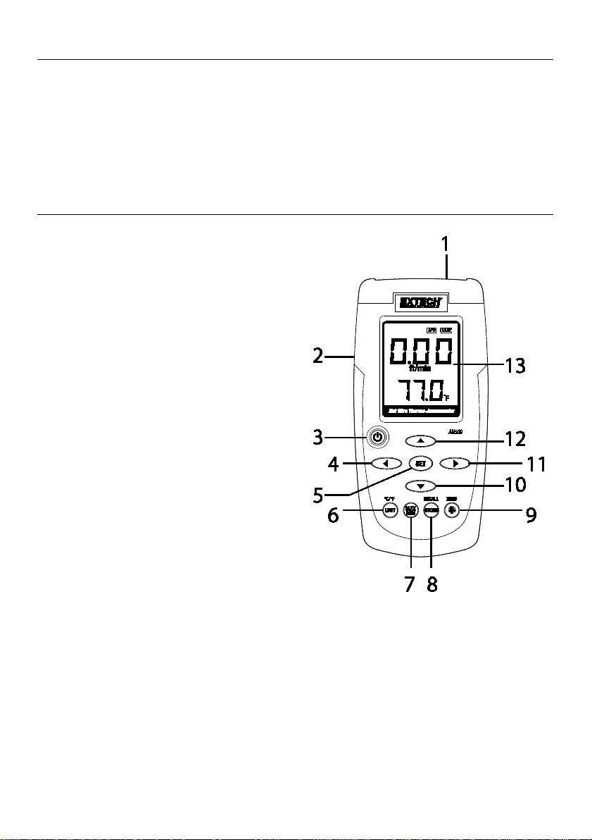
Meter Description
1. Probe input jack (insert probe plug here)
2. AC adaptor jack
3. Power ON-OFF button
4. Left arrow button
5. SET button
6. UNIT button
7. MAX-MIN button
8. STORE-RECALL button
9. ZERO and Backlight button
10. Down arrow button
11. Right arrow button
12. Up arrow button
13. LCD display
Note: Battery compartment and Tilt Stand located on the back of the meter
AN500-en-GB_v2.1 5/17
Page 3
3
Push-button Description
• Power:
• C/F: Select the temperature units
• MAX/MIN: Press to Record and track the highest (MAX) and lowest (MIN) reading
• STORE: Store readings into memory
• RECALL: Display STORED readings
• UNIT: Air velocity units or airflow units of measure
• ZERO: Press to zero the display
• BACKLIGHT:
• SET: Atmospheric compensation setting or airflow parameters setting
• ◄►▲▼: Atmospheric compensation adjustment arrows (also used for general menu
navigation)
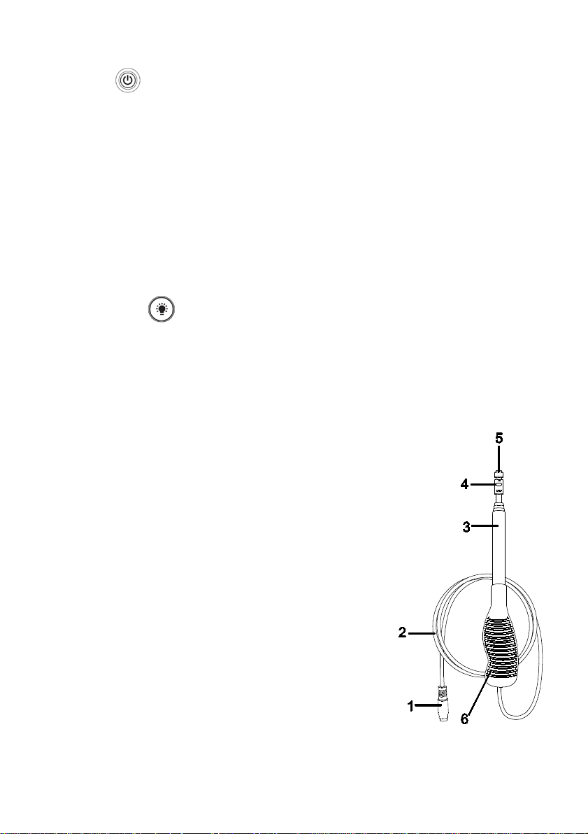
Probe Description
1. Probe Connector
2. Probe cabling
3. Telescoping sensor handle - Extends to 39” (1m)
4. Sensor opening (Air must flow through this opening against
the white dot shown on item 5 below for proper
measurement)
5. White dot air direction
6. Ergonomic handle grip
Switches the meter ON and OFF
Turn LCD backlight ON and OFF
AN500-en-GB_v2.1 5/17
Page 4

4
Operation
Initialization and Zero
The meter should always be zeroed at temperature before use using the ZERO button. Do not
rely on the initial zero display.
Notes:
The meter does not display negative numbers.
Open antenna to desired length.
1. Connect the sensor to the input jack on top of the meter and open antenna to desired length.
2. Switch the meter ON using the Power button.
3. Select the desired temperature units by holding in the C/F select button. The LCD will reflect the
selection.
4. Select the desired air velocity units using the UNIT button. The LCD will reflect the selection.
5. Place the sensor in the area to be measured and allow a short time for the sensor to reach the
temperature of the air under test.
6. Press and hold the ZERO button for 1 second to zero the meter.
Taking Air Velocity Measurements
1. Zero the meter as described above.
2. Place the sensor in the air current to be measured. Have the air flow in the direction against the
white dot shown on the top of the sensor head.
3. View the air velocity and temperature readings on the LCD Display. The top LCD display
indicates the Air Velocity reading. The lower LCD display indicates the temperature reading.
MAX/MIN Function
1. To begin capturing the Minimum (MIN), Maximum (MAX), and Average (AVG) readings, press
the MAX-MIN button momentarily. The MAX, MIN, and AVG icons will appear on the LCD
(flashing on and off).
2. Take readings as described previously.
3. Press MAX/MIN button again to stop recording.
4. The MAX-MIN-AVG display screens will automatically scroll from one to the next showing the
highest (MAX), lowest (MIN), and average (AVG) readings captur ed since the MAX-MIN button
was first pressed.
5. Press the MAX-MIN button again to continue recording. The MAX, MIN, and AVG icons will
continue flashing.
6. Press and hold the MAX-MIN button for 1 second to exit the MAX-MIN mode and return to the
normal operating screen. The MAX-MIN-AVG readings will be reset.
AN500-en-GB_v2.1 5/17
Page 5

5
Auto Power OFF
The meter is equipped with an Auto Power OFF (APO) feature. The meter will automatically switch
OFF after 10 minutes of inactivity (no button pressed). Press and hold the POWER button for 1
second to enable the APO feature (the APO display icon will switch ON). When the meter is
powered ON for the next session, the Auto Power OFF feature will be disabled again.
Change Units of Measure
1. Press the CF/UNIT button momentarily to switch between units of measure (m/s, km/hr,
ft/min, MPH, knot, CMM and CFM).
2. Press and hold CF/UNIT button for 1 second to switch between C and F temperature units.
Store Readings (Datalogging)
1. Press the RECALL/STORE button momentarily to store and hold the reading.
2. Press the RECALL/STORE button again to return to normal measurement mode.
Recall Readings
1. Press and hold the RECALL/STORE button for 1 second to enter recall mode.
2. Momentarily press the ▲, ▼, ► or ◄ button to scroll through the memory locations and view
the stored data.
3. Press the RECALL/STORE button once more to exit recall mode. The meter will display 'End'
and return to normal operation.
Up to 9500 readings can be stored in the AN500
Clear Stored Readings
While in RECALL mode press and hold ZERO button for 1 second to clear stored data. The meter
will display 'Clr' then return to normal operation.
Atmospheric Pressure Compensation Setting
1. Press and hold the SET button for 1 second to enter Atmospheric Pressure Compensation
Adjustment mode.
2. Momentarily press the ▲ or ▼ button to adjust the pressure from 502-1012 mbar*.
3. Press the SET button to enter the next step.
4. Momentarily press the ▲ or ▼ button to adjust the GAIN from 0.00-2.00. (default 0.66)
5. Press and hold the SET button for 1 second to store the settings in non-volatile memory and
return to the normal measurement mode.
Or momentarily press the SET button to return to normal operation. The atmospheric pressure
compensation parameters will reset to the previous setting when powered on the next time.
6. When in atmospheric pressure setting mode, the unit will return to normal operation if no button
is pressed for 8 seconds. The data will not be stored.
* Sea level is 1013.25mBar and 4500m (15000 ft) is 571.6mBar
AN500-en-GB_v2.1 5/17
Page 6

6
Zero Adjustment
Press and hold the ZERO button for 1 second to zero the reading.
Backlight
Press the Zero/BL button at any time to turn on/off the backlight.
Airflow Parameters Settings
1. While in airflow measurement mode press and hold SET for 1 second to enter next step.
2. Press ▲ or ▼ to adjust R (diameter). Adjustment will be from 1.5 to 101.5 cm in CMM mode or
0.6 to 40.0 in CFM mode.
3. Press SET to enter next step.
4. Press ▲ or ▼ to adjust GAIN from 0.10-1.00. (default 1.00)
5. Press and hold the SET button for 1 second to store the settings in non-volatile memory and
return to the normal measurement mode.
Or momentarily press the SET button to return normal operation. The airflow parameters will
reset to the previous setting when the meter is powered on the next time.
6. While in Airflow parameters setting mode, the unit will return to normal operation if no button is
pressed for 8 seconds. The data will not be stored.
Battery Replacement
When the displayed battery symbol begins to blink, replace the batteries as soon as practical.
If battery voltage is too low the meter will not switch ON. The batter y compartment is located on the
rear of the instrument (behind the tilt stand) secured by one Phillips head screw.
1. Open the rear battery compartment by first swiveling out the tilt stand.
2. Remove the Phillips head screw.
3. List the compartment cover to access the batteries.
4. Replace the six ‘AA’ 1.5V batteries observing polarity.
5. Replace the battery compartment cover and secure with the Phillips head screw.
Battery Safety Reminders
• Please dispose of batteries responsibly; always observe local, state, and federal regul ations
with regard to battery disposal.
• Never dispose of batteries in a fire. Batteries may explode or leak.
• Never mix battery types. Always install new batteries of the same type.
Never dispose of used batteries or rechargeable batteries in household waste.
As consumers, users are legally required to take used batteries to appropriate collection
sites, the retail store where the batteries were purchased, or wherever batteries are sold.
Disposal: Do not dispose of this instrument in household waste. The user is obligated to take
end-of-life devices to a designated collection point for the disposal of electrical and
electronic equipment.
Battery Safety Reminders
• Please dispose of batteries responsibly; always observe local, state, and federal regulations
with regard to battery disposal.
• Never dispose of batteries in a fire. Batteries may explode or leak.
• Never mix battery types. Always install new batteries of the same type.
AN500-en-GB_v2.1 5/17
Page 7

7
Specifications
Units Range
Resolution
Accuracy
General Specifications
Circuit configuration Custom one-chip LSI microprocessor circuit
Display
Measurements
Temperature Sensor Two temperature sensors
Min/Max Recording Capture Maximum (MAX), Minimum (MIN), and Average (AVG) readings
Datalogger 9500 readings can be stored and recalled
Operating Temperature 0 to 50°C (32 to 122°F)
Operating Humidity Max. 80% RH
Operating Altitude 4500m (15000ft) Maximum
Power Supply Six (6) 1.5V ‘AA’ batteries
Power Consumption Approx. 30 mADC
Weight 580g (1.28 lbs.) including batteries & probe
Dimensions Main instrument: 160 x 80 x 45 mm (6.3 x 3.1 x 1.8”)
Range Specifications
m/s
km/h 0.0 to 75.0 km/h 0.1 km/h ±(3.0%rdg+0.7km/h)
ft/min 0 to 4000 ft/min 1 ft/min ±(3.0%rdg+38ft/min)
MPH 0.0 to 45.0 MPH 0.1 MPH ±(3.0%rdg+0.4MPH)
knots 0.0 to 40.0 knots 0.1 knots ±(3.0%rdg+0.4knots)
Temperature 0 to 60oC (0 to 140 oF) 0.1 oC and oF ±1.0 oC (1.8 oF)
Units Range Resolution Gain
CMM (cubic
meters per minute)
CFM (cubic feet
per minute)
mbar 502-1012 mbar 2 mbar 0.00-2.00
Note: m/s: meters per second; km/h: kilometers per hour; ft/min: feet per minute; Knot: nautical miles per hour; MPH: miles per
hour; CMM: cubic meters per min; CFM: cubic ft per min
R : 1.5-101.5cm (0.5) or 0.6-40.0in. (0.2)
9999 count LCD with back light
m/s (meters per second), km/h (kilometers per hour), ft/min (feet/per
minute), knot (nautical miles per hour), MPH (miles per hour), CMM
3
(m
/min), and CFM (ft3/min), Temperature: °C, °F
Sensor: 8mm (0.31”) diameter
Telescoping handle with cable: 2.1m (7’) max. length with cable
0.00 to 9.99 m/s 0.01 m/s
10.0 to 20.0 m/s 0.1 m/s
0 to 1298.0 m
0 to 45922 ft3/min 1 ft3/min 0.10-1.00
Power Consumption’=(1+(1010/mbar-1)*gain)*power consumption
CMM=(60*m/sec*R*R*PI*gain)/40000 Circle
CFM=(ft/min*R*R*PI*gain)/576 Circle
3
/min 0.1 m3/min 0.10-1.00
±(3.0%rdg+0.2m/s)
AN500-en-GB_v2.1 5/17
Page 8

8
Useful Equations and Conversions
Area equations
The volume of air flowing through a duct or vent can be determined by taking the area of the duct
in square units (i.e. square feet) and multiplying this value by the measured linear velocity (i.e., feet
per minute). This gives: ft/min x ft
Cubic equations
CFM (ft3/min) = Air Velocity (ft/min) x Area (ft2)
CMM (m3/min) = Air Velocity (m/sec) x Area (m2) x 60
Units Conversion Table
m/s ft/min knot km/hr MPH
1 m/s 1 196.85 1.944 3.6 2.237
1 ft/min 0.00508 1 0.00987 0.01829 0.01136
1 knot 0.5144 101.27 1 1.852 1.151
1 km/hr 0.2778 54.68 0.54 1 0.6214
1 MPH 0.447 88 0.869 1.6093 1
All rights reserved including the right of reproduction in whole or in part in any form
2
= ft3/min (CFM)
Copyright © 2014-2017 FLIR Systems, Inc.
ISO-9001 Certified
www.extech.com
AN500-en-GB_v2.1 5/17
 Loading...