

Page 1
User's Guide
Extech AM600
600A AC Analog Clamp Meter
Page 2
Introduction
Congratulations on your purchase of the Extech AM600 Analog Clamp Meter. This device
measures AC Current, AC Voltage, DC Voltage, Resistance and Temperature. This meter
is shipped fully tested and calibrated and, with proper use, will provide years of reliable
service.
Safety
International Safety Symbols
This symbol, adjacent to another symbol or terminal, indicates the user must refer
to the manual for further information.
This symbol, adjacent to a terminal, indicates that, under normal use, hazardous
voltages may be present
Double insulation (Protection Class II)
SAFETY NOTES
• Do not exceed the maximum allowable input range of any function.
• Do not apply voltage to meter when resistance function is selected.
• Remove the battery if meter is to be stored for longer than 60 days.
WARNINGS
• Set function switch to the appropriate position before measuring.
• When measuring volts do not switch to current/resistance modes.
• Do not measure current on a circuit whose voltage exceeds 600V.
• When changing ranges always disconnect the test leads from the circuit under test.
CAUTIONS
• Improper use of this meter can cause damage, shock, injury or death. Read and
understand this user manual before operating the meter.
• Always remove the test leads before replacing the battery or fuses.
• Inspect the condition of the test leads and the meter itself for any damage before
operating the meter. Repair or replace any damage before use.
• Use great care when making measurements if the voltages are greater than 25 VAC
rms or 35 VDC. These voltages are considered a shock hazard.
• Always discharge capacitors and remove power from the device under test before
performing Resistance tests.
• Voltage checks on electrical outlets can be difficult and misleading because of the
uncertainty of connection to the recessed electrical contacts. Other means should be
used to ensure that the terminals are not "live".
• If the equipment is used in a manner not specified by the manufacturer, the protection
provided by the equipment may be impaired.
Function Maximum Input
A AC 600 A
V AC 750 V
V DC 75 V
AM600 V2.0 6/07 2
Page 3
PER IEC1010 OVERVOLTAGE INSTALLATION CATEGORY
OVERVOLTAGE CATEGORY I
Equipment of OVERVOLTAGE CATEGORY I is equipment for connection to circuits in
which measures are taken to limit the transient overvoltages to an appropriate low level.
Note – Examples include protected electronic circuits.
OVERVOLTAGE CATEGORY II
Equipment of OVERVOLTAGE CATEGORY II is energy-consuming equipment to be
supplied from the fixed installation.
Note – Examples include household, office, and laboratory appliances.
OVERVOLTAGE CATEGORY III
Equipment of OVERVOLTAGE CATEGORY III is equipment in fixed installations.
Note – Examples include switches in the fixed installation and some equipment for industrial
use with permanent connection to the fixed installation.
OVERVOLTAGE CATEGORY IV
Equipment of OVERVOLTAGE CATEGORY IV is for use at the origin of the installation.
Note – Examples include electricity meters and primary over-current protection equipment
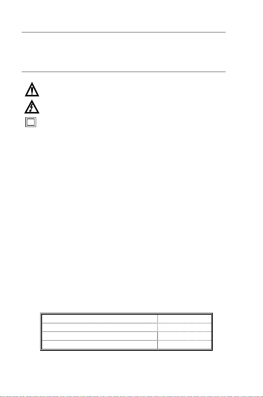
Description
Meter Description
1. Current clamp
2. Clamp opening trigger
3. 0 Ohms adjustment
4. Meter zero adjustment
5. Scale
6. “COM” Terminal
7. Range switch
8. Pointer Lock switch
9. V, Ω and Temp Terminal
AM600 V2.0 6/07 3
Page 4
Operation
NOTE: Read and understand all Warning and Caution statements in this operation manual prior to using
this meter.
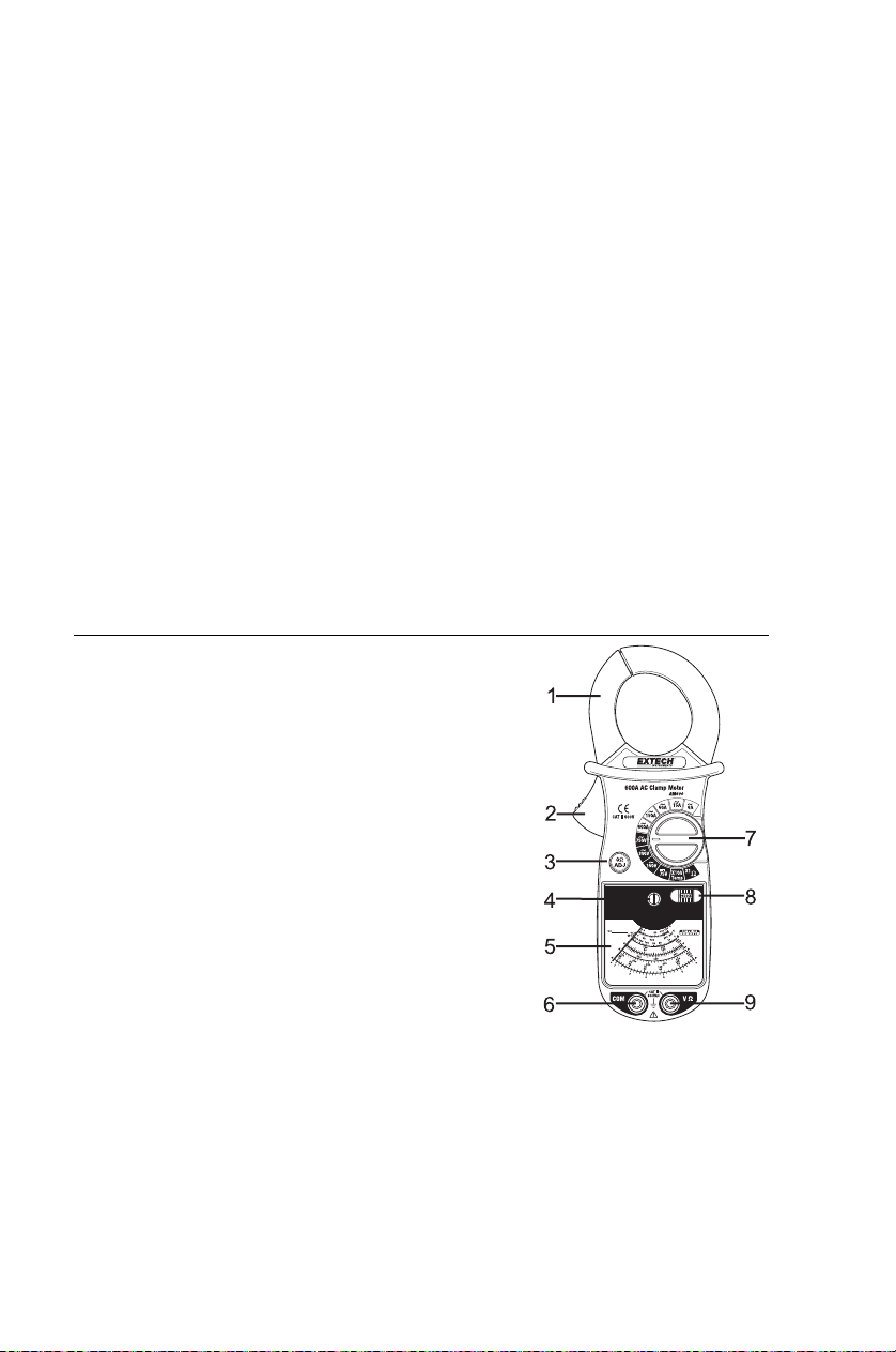
AC Current Measurements
WARNING: Remove the test leads from the meter before making current clamp
1. Set the Range switch to the 600A range..
2. Set the Pointer Lock
3. If necessary, turn the
4. Press the trigger to open
5. The analog display
6. When possible, set the Range switch to a lower range to obtain a reading in the
measurements.
switch is set to the rightmost position so that the
pointer may freely move.
Zero Adjust screw to
zero the meter display.
jaw. Fully enclose only
one conductor. For
optimum results, center
the conductor in the jaw.
pointer will indicate the current reading.
upper half of the scale.
AC/DC Voltage Measurements
1. Insert the black test lead into the negative COM terminal and
the red test lead into the positive V terminal.
2. Set the Range switch to the highest AC or DC Voltage range.
3. Set the Pointer Lock switch is set to the right-most position so
that the pointer may freely move.
4. If necessary, turn the Zero Adjust screw to zero the meter
display.
5. Connect the test leads in parallel to the circuit under test.
6. The analog display pointer will indicate the voltage reading.
7. When possible, set the Range switch to a lower range to
obtain a reading in the upper half of the scale.
AM600 V2.0 6/07 4
Page 5
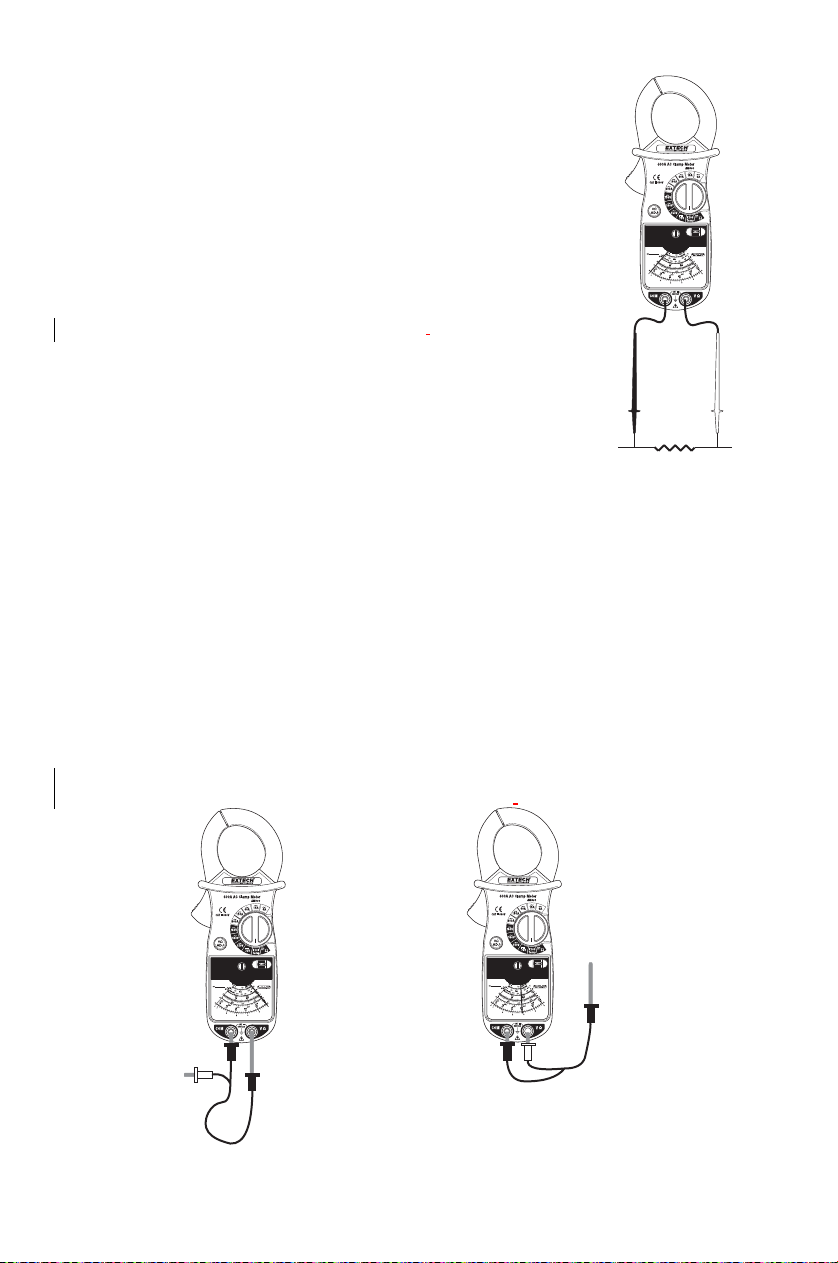
Resistance Measurements
1. Insert the black test lead into the negative COM terminal and
the red test lead into the OHMS positive terminal.
2. Set the Range switch to the X1Ω or X100Ω position as
needed.
3. Set the Pointer Lock switch is set to the right-most position so
that the pointer may freely move.
4. With the test leads open, adjust the meter zero so that the
pointer is over the ∞ symbol.
5. Touch the test lead tips together and adjust the 0 Ohms adjust
until the pointer is over the 0 ohms posi
6. Touch the test probe tips across the circuit or component under
test.
7. The analog display pointer will indicate the resistance reading.
tion.
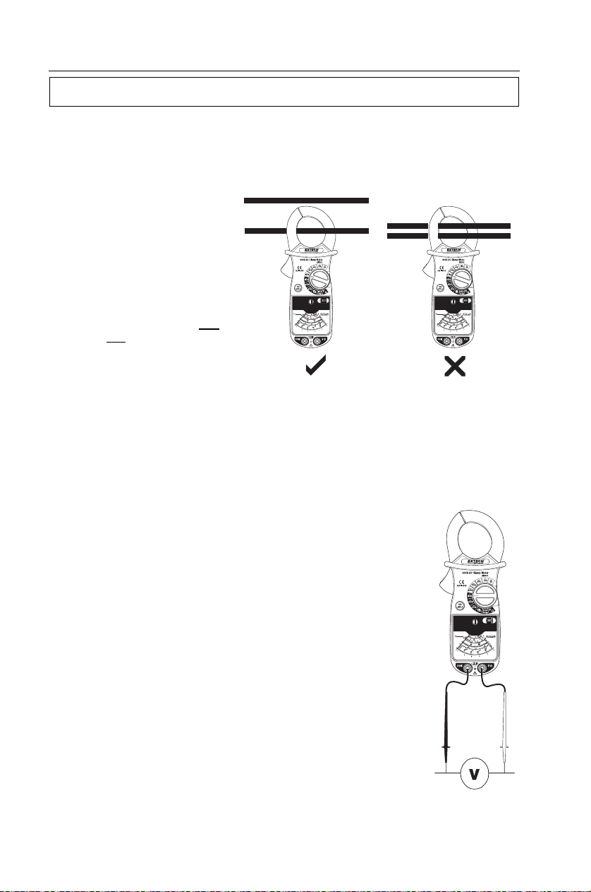
Temperature Measurements
Zero procedure (fig. 1)
1. Insert the temperature probe black plug into the COM terminal and the Probe tip
into the V Ω terminal.
2. Adjust the pointer for a 0 Ω scale reading
Measurements (fig. 2)
1. Insert the temperature probe black plug into the COM terminal and the red plug
into the V Ω terminal.
2. Place the temperature probe into the area to be tested.
3. Read the temperature on the °C or °F temperature scale
fig. 1 fig. 2
AM600 V2.0 6/07 5
Page 6

Pointer Lock Function
The Pointer Lock switch freezes the pointer’s position and is used as a ‘data hold’ feature.
This feature is useful in dimly lit or hard to reach locations.
Specifications
Function Ranges Accuracy
(50/60Hz)
AC Voltage
(50/60Hz)
DC Voltage 75 V DC ± 3% of Full Scale
Resistance
Temperature -4 to 302°F (-20°C to 150°C) ± 3% of arc
Clamp jaw opening 1.3" (34 mm) max.
Display Analog with Zero Adjustment
Input Impedance ACV: 2 kΩ/V, DCV: 4.5 kΩV
AC bandwidth 50 / 60 Hz
Temperature Probe Thermistor
Operating conditions Temperature 32 - 104°F (0 - 40°C); Relative Humidity <80%
Operating Altitude 7000 ft. (2000 m) maximum.
Battery One (1) 1.5V ‘AA’ Battery
Fuse 500 mA, 250V fast
Dimensions & Weight 8.4 x 3.4 x 1.7" (214 x 85 x 43 mm); 12.4 oz. (350 g)
Safety For indoor use and in accordance with the requirements for
Standards
6, 15, 60, 150 A ± 3% of Full Scale AC Current
600 A ± 5% of Full Scale
150, 300 and 750V ± 3% of Full Scale
2000 Ω (50 Ω mid-scale) (Rx1)
± 3% of Full Scale Length
200 kΩ (5 kΩ mid-scale) (Rx100)
double insulation to IEC1010-1 (2001): EN61010-1 (2001)
Overvoltage Category II 600V, Pollution Degree 2.
C
C
AM600 V2.0 6/07 6
Page 7

Maintenance
WARNING: To avoid electrical shock, disconnect the meter from any circuit and remove the test leads from
the input terminals before opening the case. Do not operate the meter with an open case.
Cleaning and Storage
Periodically wipe the case with a damp cloth and mild detergent; do not use abrasives or
solvents. If the meter is not to be used for 60 days or more, remove the battery and store it
separately.
Battery Replacement
1. Remove the Phillips head screws from the rear battery compartment cover.
2. Replace the 1.5V ‘AA’ battery and replace the cover.
Fuse Replacement
1. Remove the two (2) Phillips head screws from the rear cover.
2. Carefully lift off the rear cover.
3. Replace the 0.5A/250V fuse. Make sure the fuse is centered in the fuse holder.
4. Replace the rear cover.
Calibration and Repair Services
Extech offers repair and calibration services for the products we sell. Extech also
provides NIST certification for most products. Call the Customer Care Department for
information on calibration services available for this product. Extech recommends that
annual calibrations be performed to verify meter performance and accuracy.
AM600 V2.0 6/07 7
Page 8

Warranty
EXTECH INSTRUMENTS CORPORATION warrants this instrument to be free of defects
in parts and workmanship for one year from date of shipment (a six month limited warranty
applies to sensors and cables). If it should become necessary to return the instrument for
service during or beyond the warranty period, contact the Customer Service Department at
(781) 890-7440 ext. 210 for authorization or visit our website www.extech.com for contact
information. A Return Authorization (RA) number must be issued before any product is
returned to Extech. The sender is responsible for shipping charges, freight, insurance and
proper packaging to prevent damage in transit. This warranty does not apply to defects
resulting from action of the user such as misuse, improper wiring, operation outside of
specification, improper maintenance or repair, or unauthorized modification. Extech
specifically disclaims any implied warranties or merchantability or fitness for a specific
purpose and will not be liable for any direct, indirect, incidental or consequential damages.
Extech's total liability is limited to repair or replacement of the product. The warranty set
forth above is inclusive and no other warranty, whether written or oral, is expressed or
implied.
Technical Support: Extension 200; E-mail: support@extech.com
Repair & Returns: Extension 210; E-mail: repair@extech.com
Product specifications subject to change without notice
For the latest version of this User Guide, Software updates, and other up-to-the-
minute product information, visit our website: www.extech.com
Extech Instruments Corporation, 285 Bear Hill Road, Waltham, MA 02451
Support line (781) 890-7440
All rights reserved including the right of reproduction in whole or in part in any form.
Copyright © 2007 Extech Instruments Corporation
AM600 V2.0 6/07 8
 Loading...