

Page 1
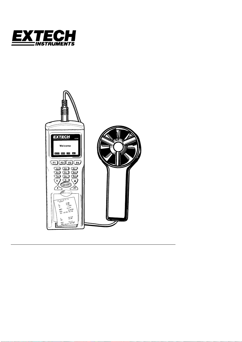
User's Guide
Datalogging / Printing Anemometer +
Psychrometer
Model 451181
Introduction
Congratulations on your purchase of the Extech 451181 Datalogging / Printing
Anemometer + Psychrometer. This device simultaneously measures and displays Air
Velocity, Temperature, Humidity, Wet Bulb Temperature, and Air Volume (CFM / CMM).
The datalogger stores 2400 readings in Automatic Recording mode and 99 readings in
Manual Recording mode. The Printer provides a hard copy of individual readings while
the PC software permits downloading of data for use in spreadsheets, database, and
other programs. This meter is shipped fully tested and calibrated and with proper use will
provide years of reliable service.
Page 2
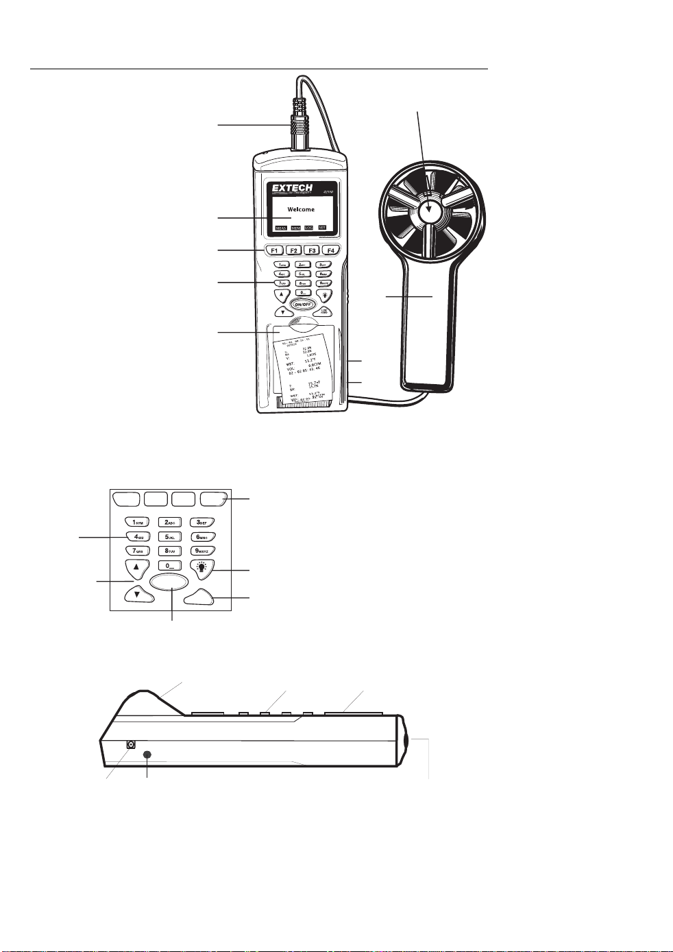
Meter Description
1. Sensor plug
2. LCD Display
3. F1 through F4 softkeys
4. Keypad
5. Printer paper and paper
compartment
6. AC Adapter jack
7. RS-232c TTL output
jack
8. Vane air velocity sensor
9. Temperature and
humidity sensor
housing (must be
opened before use)
The battery compartment is
located on the back of the
instrument. There are two (2)
tripod mounts; one on the rear
of the meter and one on the
rear of the vane handle.
F1 F2 F3 F4
Alphanumeric
Keypad
Up / Down
Arrow keys
Press to turn meter ON or OFF
ON / OFF
1
2
3
4
5
Line
Feed
Paper
Compartment
Function
Soft-keys
Display
Backlight
Printer
Paper Feed
Keypad Display
9
8
7
6
AC Adapter
RS-232 Interface
Sensor jack
2
Model 451181 Version 3.0 07/06
Page 3
Operation
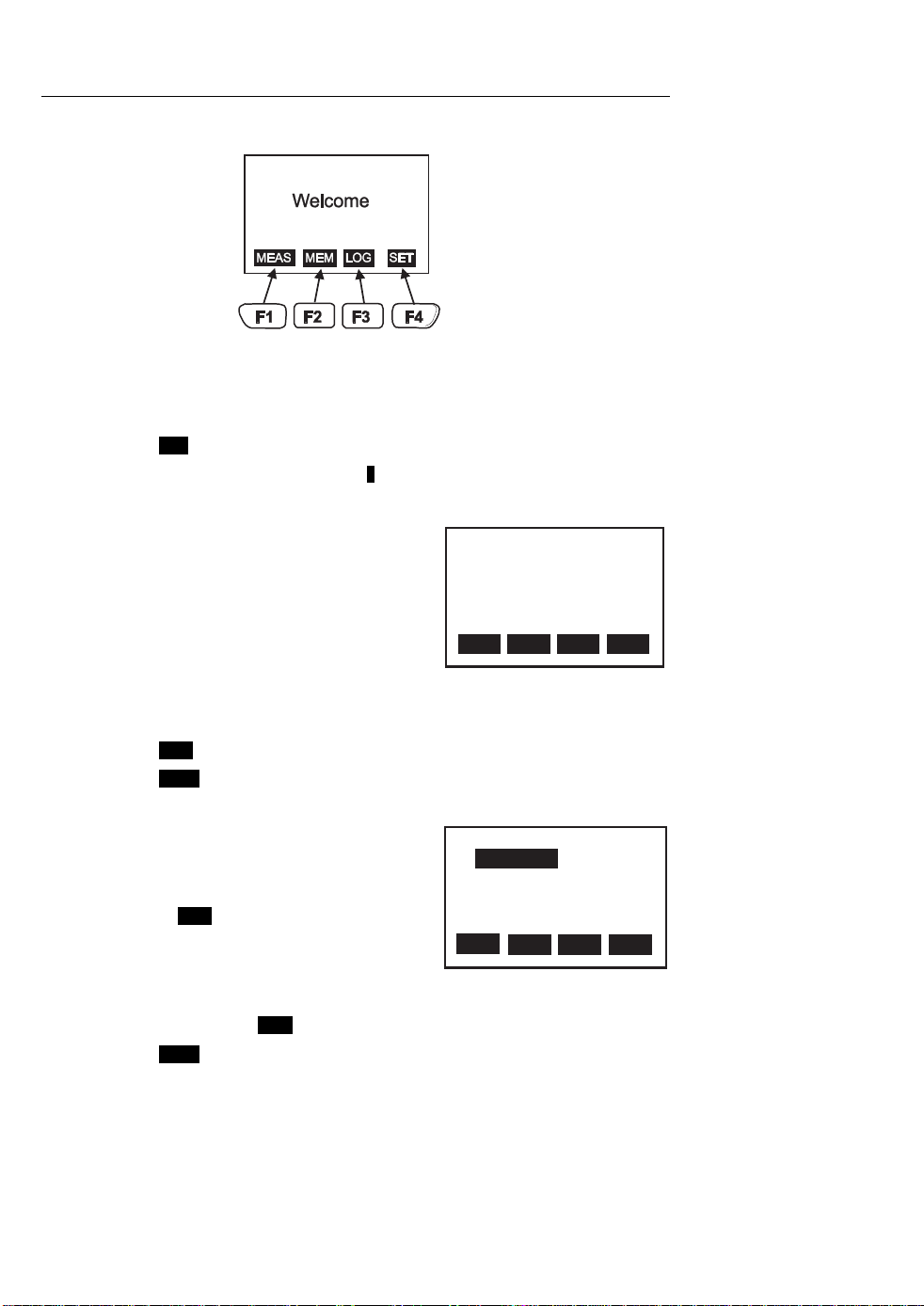
Press the ON/OFF button to power the meter. The WELCOME screen will appear along with
four softkey selections (F1 through F4):
Setup
The Setup Screens provides access to the LCD Contrast, Printer Contrast, Auto Power-Off
time, Auto Power-Off Enable/Disable, Calendar Clock, and View configuration.
Setup Screen 1
1. Press F4 SET from the WELCOME screen to access the 1st setup screen.
2. Use the ▲ or ▼ arrow keys to move the 1 cursor to the desired position.
3. The programmable parameters for the first setup screen are as follows:
• LCD Cont: Adjust the LCD contrast (1-5)
using the numeric keypad.
• Prn Cont: Adjust the print contrast (1-9)
using the numeric keypad.
• Auto Power Off Time: Set the time period
that the instrument will wait before
automatically shutting down (1 to 20
minutes)
• Auto Power Off Enable/Disable: With the Auto Power Off disabled, the meter
will not automatically shut down.
4. Press F1 EXIT to exit the setup mode.
5. Press F4 NEXT to access the second setup screen for real time clock setup.
Setup Screen 2
1. Use the ▲ or ▼ arrow keys to highlight the
desired text to edit.
2. The order of DAY (DD), MONTH (MM), and
YEAR (YY) can be edited by highlighting and
pressing F2 EDIT.
3. The Date and Time can be set by highlighting
with the ▲ or ▼ arrow keys and programming
with the alphanumeric keys.
4. The SET ID can be set to ENABLE if a custom ID will be used. Use the ▲ or ▼ arrow
keys to highlight and F2 EDIT to change the setting.
5. Press F4 NEXT to access the third setup screen’s ITEM list.
LCD Cont. (1 - 5): 3
Prn Cont. (1 - 9): 5
Auto Off: 20 mins.
EXIT PRNEDIT NEXT
MAIN SETUP SCREEN 1
Set Clock:
DD-MM-YY
07-07-05 02:10:20
Set ID: Disable
ID:
EXIT
MAIN SETUP SCREEN 2
Enable
HH:MM:SS
PRNEDIT NEXT
3
Model 451181 Version 3.0 07/06
Page 4

Setup Screen 3
1. Measurement parameters with a check mark will
be included on the measurement screen. Items
with an ‘X’ will not be shown in the measurement
screen. Use the ▲ or ▼ arrow keys to select an
item and then use F2 EDIT to change from ‘X’ to a
check mark or from a check mark to an ‘X’.
2. The unit of measure shown next to each
measurement parameter can also be altered by
first selecting with the ▲ or ▼ arrow keys and
then adjusting using F2 EDIT.
Select item
V FPM
TF
RH %
√
√
√
WBT x F
VOL CFM
EXIT
√
PRNEDIT NEXT
MAIN SETUP SCREEN 3
4
Model 451181 Version 3.0 07/06
Page 5

Measurement Procedure
Air Velocity, Temperature, Relative Humidity, and Wet Bulb Measurements
1. Turn the instrument ON by pressing the ON/OFF button.
2. Turn the temperature/humidity
sensor cover (located at the
center of the vane) to the
OPEN position. This will
expose the sensors to the air
flow in order to provide
temperature, humidity, and wet
bulb readings (see diagram).
3. Press F1 MEAS to enter the
measurement mode.
4. Hold the vane sensor in the
stream of air with the vane’s
temperature and humidity
sensors facing the oncoming
air stream.
5. Read the Air Velocity, Temperature, Relative Humidity, Wet Bulb Temperature, and
Air Volume readings on the LCD (see
diagram).
6. Use F1 EXIT to leave the measurement
window.
7. Use F2 INPUT to begin programming
the area of the duct, or other enclosure,
necessary for Air Volume (CFM / CMM)
measurements. Refer to the separate
section on Air Volume measurements.
8. Use F4 PRN to print the measurement
data (see next paragraph).
9. Move the rotating sensor cover to the closed position when the meter is not in use.
See diagram above.
_
_
_
_
_
_
_
_
C
L
N
E
P
O
O
S
E
T: RH:
75.7oF 58.4%
V: FPM
98.0
WBT: VOL:
66.1oF 0.0CFM
EXIT PRNINPUT
MEASUREMENT (MEAS) SCREEN
Printing Measurements
1. Perform the Measurement procedure as described above.
2. Press F4 PRN and answer YES when prompted.
3. The instrument will print all the displayed data with
date/time stamps. See sample printout at right.
4. Press the LINE FEED button to feed the paper.
5
ACME CORP.
V: 600 MPH
T: 75.2 F
RH: 46.5%
WBT:61.3 F
VOL:174 CFM
06-17 01:49:07
SAMPLE PRINTOUT
Model 451181 Version 3.0 07/06
Page 6

Air Volume Measurements
Air Volume (CFM / MM) measurements require that the area of the duct or other enclosure
be known. The meter can calculate the area of rectangular and circular ducts or the user
can calculate the area and enter it manually. See details below:
1. Measure (in inches) the diameter of a circular duct or the length/width of a
rectangular duct. Optional: Calculate the duct area.
2. Press F1 MEAS from the WELCOME screen.
3. Press F2 INPUT softkey.
4. If the area (in square inches) has been manually calculated, press AREA and enter
the value using the numeric keypad; Press ENTER, then proceed to step 6.
Otherwise continue with step 5.
5. For rectangular ducts, press LxW (length x width) and enter the length (in inches)
of the duct (using the numeric keypad). Press ENTER and do the same for the
width. Press ENTER after the width is programmed. For circular ducts, press the D
(diameter) key. Enter the duct’s diameter (in inches) using the numeric keypad and
then press ENTER.
6. Take an air velocity measurement as previously described.
7. Read the CFM or CMM Air Volume measurement on the LCD.
6
Model 451181 Version 3.0 07/06
Page 7

Manual Datalogging Mode
The Model 451181 has two datalogging modes, MEM Manual Datalogging (99 records
maximum) and Automatic Datalogging LOG (2400 records maximum). This section covers
Manual Mode and the following section covers Automatic Mode.
Manual Datalogging basics
To take a reading and store it in memory:
1. Press F2 MEM from the WELCOME screen.
2. Use the arrow buttons to select a memory location (1 through 99) shown in the
upper left hand corner of the LCD.
3. Press F2 MEAS and then take a measurement.
4. At any time during the measurement, press F4 SAVE or F1 ABORT.
Manual Datalogging Display screens 1 and 2
Manual mode uses two display screens as shown below. Each screen has its own
softkeys. Other than the softkey differences, the screens are identical, showing the
measurement results.
To get to the 1
Memory display screen will appear with the memory location number (1 through 99) shown
in the upper left hand corner.
Softkeys for Memory Screen 1
• F1 EXIT: Press to return to the WELCOME
screen
• F2 MEAS: Press to take a measurement.
ABORT (F1) and SAVE (F4) keys will be active.
Press SAVE to store the current reading in the
selected memory location. Press ABORT to
return to the previous screen.
• F3 EDIT: Press to begin customizing the header
in the current memory location. The ABORT
(F1), CLR (F2), BACK (F3), and ENTER (F4)
softkeys will be active. Customizing a header is explained in detail in the next section.
• F4 NEXT: Press to access the second Memory display screen. Memory screen two is
identical to screen 1 except that screen 2 has F1 EXIT, F2 CLR (clear), F3 PRN
(Print), and F4 BACK softkeys described below.
st
memory screen press F2 MEM from the WELCOME screen. The first
01: 07-06 05:42:50
V: 98.0FPM
T: 82.0loF
RH: 62.7%
WBT: 72.2oF
VOL: 0.0CFM
EXIT NEXTMEAS
EDIT
MEMORY (MEM) SCREEN 1
Softkeys for Memory Screen 2
• F1 EXIT: Press to return to the WELCOME
screen
• F2 CLR: Press to clear the header for the
selected memory location.
• F3 PRN: Press to print the data in the current
memory location.
• F4 BACK: Press to return to memory screen 1.
01: 07-06 05:42:50
V: 98.0FPM
T: 82.0loF
RH: 62.7%
WBT: 72.2oF
VOL: 0.0CFM
EXIT BACKCLR
PRN
MEMORY (MEM) SCREEN 2
7
Model 451181 Version 3.0 07/06
Page 8

Customizing a Memory Location Header
Using the F3 EDIT softkey in Memory screen 1, as described above, allows the user to
customize the header in the currently selected memory location.
1. Use the ▲ or ▼ arrow keys to step forward and backward in the header.
2. Use the BACK softkey to step backward
and erase characters while stepping.
3. Use the alphanumeric keypad to compose
a header. For example, press the ‘2’ key
and a window with the characters related
to the ‘2’ key will appear (namely,
2abcABC as shown in the diagram). Then
use the ‘2’ key again to scroll through the
character list. When the desired character
is highlighted the meter will automatically
place that character in the header.
4. F2 CLR is used to erase the header.
5. F4 ENTER is used to save the header.
Viewing Stored Readings
1. From the WECLOME screen, press F2 MEM
2. Use the ▲ or ▼ arrow keys to scroll through the memory locations that contain the
stored data.
3. Press F1 EXIT to return to the WELCOME screen.
Printing Stored Data
Proceed to the second memory screen as previously described and use F3 PRN to print a
data record. Use the ▲ or ▼ arrow keys to select the desired data location (0- to 99) to
print.
01:
V: 98.0FPM
T: 82.0loF
RH: 62.7%
WBT: 72.2oF
VOL: 0.0CFM
2abcABC
EXIT NEXTMEAS
HEADER EDITING
EDIT
Erasing Data
From the second memory display screen (discussed earlier), press F2 CLR softkey.
Answer YES when prompted to erase ALL recorded readings. Press NO to abort the
clearing process.
8
Model 451181 Version 3.0 07/06
Page 9

Automatic Datalogging Mode
In the Automatic Datalogging mode the Model 451181 can automatically measure and
store 2400 readings at a programmed sample rate. To begin, press F3 LOG from the
WELCOME display to access LOG screens 1 and 2:
LOG SCREEN 1
F1 EXIT: Press to return to the WELCOME
screen
F2 START: Press to begin automatic Datalogging
at the pre-set sampling interval. Datalogging will
begin at the date/ time programmed in the SETUP
mode (see below).
0001: 07-06 05:42:50
V: 98.0FPM
T: 82.0loF
RH: 62.7%
WBT: 72.2oF
VOL: 0.0CFM
P-PG BACKN-PG
PRN
F3 SET: Setup mode (explained in detail in the
following section).
LOG SCREEN 2
F4 NEXT: Advances to LOG SCREEN 2
described below:
LOG SCREEN 2
F1 P-PG: Access Previous Page (previous 100
stored readings)
F2 N-PG: Access Next Page (next 100 stored
readings)
F3 PRN: Print page
F4 BACK: Return to LOG SCREEN 1
0001: 07-06 05:42:50
V: 98.0FPM
T: 82.0loF
RH: 62.7%
WBT: 72.2oF
VOL: 0.0CFM
EXIT NEXTSTART
SET
LOG SCREEN 1
Automatic Datalogging SETUP mode
As mentioned in Softkey Group 1 above, the F3 SET selection allows the user to configure
the datalogger for the following parameters:
BEGIN: Calendar date when datalogging will
automatically begin
START: Time of day that datalogging will begin
END: Calendar date when datalogging will end
SUSPEND: Time of day that datalogging will
cease each day
RATE: Sampling interval (time between recorded
readings)
EXPECT: Total number of readings (2400)
REMAIN: Memory locations remaining
Begin: 01-01-05
Start: 00:00:01
End: 02-02-05
Suspend: 23:59:59
Rate:
Expect: 2400 Points
Remain: 2393 Points
EXIT NEXTEDIT
15 secs
VIEW
AUTO DATALOGGER SETUP 1
The two SETUP screens are identical but for the softkey differences (see diagrams). The
softkey functions for both SETUP screens are as follows:
EXIT: Returns to WELCOME screen.
EDIT: Select display field for editing.
VIEW: Calls up the stored readings log.
NEXT: Switches to SETUP screen 2.
START: Activates the datalogger
CLR: Erases all readings stores in the automatic
datalogger memory.
PRN: Prints the datalogger memory record
BACK: Switches to the SETUP screen 1.
9
Begin: 01-01-05
Start: 00:00:01
End: 02-02-05
Suspend: 23:59:59
Rate:
Expect: 2400 Points
Remain: 2393 Points
START BACKCLR
15 secs
PRN
AUTO DATALOGGER SETUP 2
Model 451181 Version 3.0 07/06
Page 10

To edit the fields in the datalogger display screens:
1. Use the up and down ▲ or ▼ arrow keys to scroll through the parameters.
2. When a parameter is highlighted, use F2 EDIT to open it for editing.
3. Use the alphanumeric keypad to edit the parameter.
4. Press F4 ENTER to save changes. Press F1 ABORT to cancel changes.
5. Press the F1 EXIT to return to the SETUP screen.
Recording Data in the Automatic Datalogging Mode
1. After configuring the datalogger using the SETUP screens as described above,
place the meter in position to take readings (a tripod mount is provided on the rear
of the instrument for convenience).
2. Press F3 LOG from the WELCOME screen and then press F2 START.
3. Recording will begin on the date and time programmed at the BEGIN and START
lines in the SETUP screen.
4. The Datalogger will record everyday from the START time to the SUSPEND time.
The last day that datalogging will take place is the date programmed in the END
line.
5. When the logging begins, the screen should indicate LOGGING...
6. If the screen does not indicate logging at the programmed start time, make sure the
START key was pressed. Also check the section below entitled “Automatic
Datalogging START and END date considerations” for troubleshooting.
7. To stop logging before the programmed SUSPEND time, press F1 STOP.
8. To view the data recorded, press F4 VIEW.
9. To print data from the list, press F3 PRN. Press F2 when the PRINT? display
appears.
10. To clear (erase) the recorded data, access the LOG mode from the WELCOME
screen. Select SET and then press and hold the CLR (clear) softkey until the
display prompts for confirmation. Select YES to delete all records, or NO to abort
the clearing process.
Automatic Datalogging START and END Date Considerations
1. If the START date is set to a date before the current date, the datalogger will start
the moment the START softkey is pressed.
2. The datalogger will not start logging if the END date is set to a date before the
current date.
Software
Instructions for downloading and saving data to a PC can be found on the software disk
supplied with the meter.
10
Model 451181 Version 3.0 07/06
Page 11

Specifications
General Specifications
Display Backlit Multi-function LCD
Datalogger memory 2400 readings in Auto mode (99 readings in Manual mode)
Over range indication "-------" appears on the LCD
Printer 38mm printer includes Data/Time Stamp with each reading
PC Interface RS-232C (TTL level)
PC Software Windows 95/98/NT/2000/ME/XP software included
Low battery indication Battery symbol appears on the LCD
Power supply Four (4) 1.5V ‘AA” batteries or optional 6V (1000mA) adapter
Operating current 500mA (printing)
Auto Power OFF Adjustable form 1 to 20 minutes
Operating Temperature 32 to 122
Operating Humidity 90% Relative Humidity maximum
Dimensions/Weight 8.1 x 2.75 x 2.0” (208 x 70 x 53mm) / 9.2 oz. (260g) w/battery
Range Specifications
Measurement type Range Resolution Accuracy
Air Velocity * 60.0 to 5000 ft/min
Temperature (oF & oC) -4.0 to 144.0ºF
Relative Humidity (RH) 0.0 to 100.0% 0.1% ±3% (10 to 90%)
Air Volume (CFM / CMM) 0.0 to 9999.9 then
Wet Bulb Temperature
(WBT)
* Air Velocity Units
• FPM (feet per minute)
• KNT (knots)
• KMH (kilometer per hour)
• MPH (miles per hour)
• MPS (meters per second)
o
F (0 to 50oC)
0.4 to 25.0 m/sec
0.8 to 50 knots
1.5 to 90 km/hr
0.9 to 56 mph
(-20.0 to 60.0
o
C)
10000 to 99999
-7.6 to 158.0ºF
(-22.0 to 70.0
o
C)
0.1 ft/min
0.1 m/sec
0.1 knots
0.1 km/hr
0.1 mph
o
F
0.1
o
0.1
C
0.1CFM/CMM
1CFM/CMM
o
F
0.1
o
0.1
C
±(3%rdg + 19.7ft/min)
±(3%rdg + 0.1m/s)
±(3%rdg + 0.2knots)
±(3%rdg + 0.4km/hr)
±(3%rdg + 0.2mph)
o
F (1oC)
±2
±3%
Not specified
11
Model 451181 Version 3.0 07/06
Page 12

Maintenance
Cleaning
Wipe instrument with damp cloth as needed. Do not apply solvents or abrasives to the
meter. Store in a cool dry place with the batteries removed.
Battery Replacement
When the batteries weaken, the LCD display will dim or go completely blank. To replace
the batteries, open the rear battery compartment and insert four (4) new 1.5V ‘AA’ batteries
with correct polarity position.
Paper roll replacement
When the paper roll is depleted, flip up the paper compartment lid, feed the paper through
the paper slit, and feed the paper using the Line Feed button. Place the roll in the
compartment and snap the compartment cover shut preventing the paper from falling out.
Hint: Folding the paper into a point allows the paper to “catch” a bit easier when feeding it
through the slit (see diagram).
New paper rolls are available through Extech Instruments and Extech distributors.
NOTE: Thermal paper prints on only one side. Ensure paper is positioned properly as
shown in diagram.
Fold paper
as shown
when feeding
new roll
12
Model 451181 Version 3.0 07/06
Page 13

Warranty
EXTECH INSTRUMENTS CORPORATION warrants this instrument to be free of defects
in parts and workmanship for one year from date of shipment (a six month limited
warranty applies on sensors and cables). If it should become necessary to return the
instrument for service during or beyond the warranty period, contact the Customer
Service Department at (781) 890-7440 ext. 210 for authorization or visit our website at
www.extech.com (click on ‘Contact Extech’ and go to ‘Service Department’ to request an
RA number). A Return Authorization (RA) number must be issued before any product is
returned to Extech. The sender is responsible for shipping charges, freight, insurance
and proper packaging to prevent damage in transit. This warranty does not apply to
defects resulting from action of the user such as misuse, improper wiring, operation
outside of specification, improper maintenance or repair, or unauthorized modification.
Extech specifically disclaims any implied warranties or merchantability or fitness for a
specific purpose and will not be liable for any direct, indirect, incidental or consequential
damages. Extech's total liability is limited to repair or replacement of the product. The
warranty set forth above is inclusive and no other warranty, whether written or oral, is
expressed or implied.
Calibration and Repair Services
Extech offers repair and calibration services for the products we sell. Extech also provides
NIST certification for most products. Call the Customer Service Department for information
on calibration services available for this product. Extech recommends that annual
calibrations be performed to verify meter performance and accuracy.
All rights reserved including the right of reproduction in whole or in part in any form.
Technical support: Extension 200; E-mail: support@extech.com
Repair & Returns: Extension 210; E-mail: repair@extech.com
Product specifications subject to change without notice
For the latest version of this User’s Guide, Software updates, and other
up-to-the-minute product information, visit our website: www.extech.com
Extech Instruments Corporation, 285 Bear Hill Rd., Waltham, MA 02451
Copyright © 2006 Extech Instruments Corporation
Support line (781) 890-7440
13
Model 451181 Version 3.0 07/06
 Loading...