

Page 1
User’s Manual
High Temperature InfraRed Thermometer
with Laser Pointer
MODEL 42545
Page 2
Introduction
Congratulations on your purchase of the Model 42545A IR Thermometer. The 42545A is
capable of non-contact (infrared) temperature measurements at the touch of a butto n. The
built-in laser pointer increases target accuracy while the backlit LCD and handy pushbuttons combine for convenient, ergonomic operation. This meter is shipped fully tested
and calibrated and, with proper use, will provide years of reliable service.
Safety
• Use extreme caution when the laser pointer beam is on
• Do not point the beam toward anyone's eye or allow
the beam to strike the eye from a reflective surface
• Do not use the laser near explosive gases or in other
potentially explosive areas
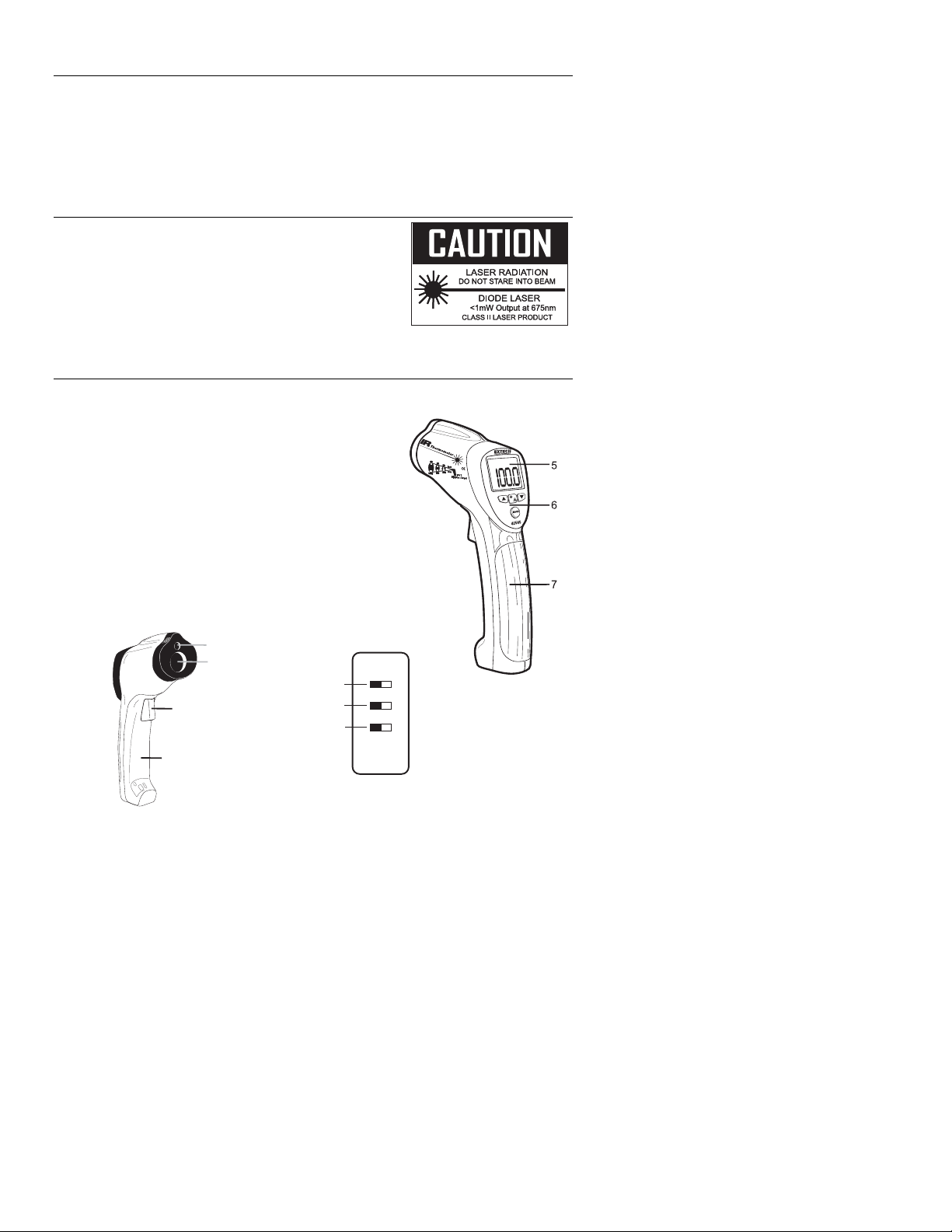
Meter Description
1. Laser pointer beam
2. IR Sensor
3. Measurement Trigger
4. Battery and Switch Compartment
5. LCD Display
6. Push-buttons
7. Handle Grip
8. Temperature Units (ºC/ºF) Switch
9. Test Lock ON/OFF Switch
10. Alarm ON/OFF Switch
Note: There is a tripod mount on the bottom of the handle
1
2
8
3
4
9
10
2
42545A-EU V4.1 03/09
Page 3

Operating Instructions
Basic IR Measurements
1. Hold the meter by its handle and point it toward the surface to be measured.
2. Pull and hold the trigger to turn the meter on and begin testing. The temperature
reading, the flashing ‘SCAN’ icon, the emissivity, and the unit of measure will appear.
Note: Replace the 9V battery if the display does not switch on.
3. Release the Trigger and the reading will hold for approximately 7 seconds (HOLD will
appear on the LCD) after which the meter will automatically shut off. The only
exception to this is if the TEST LOCK switch is set to ON.
Note: Select the temperature units (ºF/ºC) using the top switch inside the battery
compartment
Backlight/Laser Pointer
1. While pulling the Trigger, push the backlight/laser button once to turn on the
backlight.
2. Press it again to turn on the laser pointer. When the laser is ON the laser icon will
appear in the LCD.
3. Press the laser button to turn the backlight off.
4. Pressing it again turns the laser off.
Note: Backlight and Laser settings will be retained after the meter powers down.
Over-range Indication
If the temperature measurement exceeds the specified temperature range, the
thermometer will display dashes in place of a temperature reading.
High and Low Alarm Feature
The Model 42545a has an alarm feature whereas a High Alarm setting and a Low Alarm
setting can be programmed by the user. When either Alarm point is reached the meter will
alert the user via an audible beep and LCD display icon. Follow the steps below:
1. Press the MODE button until the HAL (High Alarm) parameter is displayed. Use the
UP and DOWN arrow keys to set the desired High Alarm temperature setting.
2. Press the MODE button until the LAL (Low Alarm) parameter is displayed. Use the
UP and DOWN arrow keys to set the desired Low Alarm temperature setting.
3. When an alarm limit is reached, the audible alarm will sound and the display icon
HIGH or LOW will appear on the LCD.
4. Note that if the bottom switch (located in the battery compartment) is set to OFF, the
audible alarm will be disabled.
3
42545A-EU V4.1 03/09
Page 4

The MODE button options
The MODE button is used to access the programming functions of the instrument. The
selected function is displayed on the bottom line of the LCD. Each parameter is listed
below with an explanation for its use. Press the MODE button to step from one parameter
to the next.
EMS (Emissivity Value)
To change the emissivity value, use the UP and DOWN arrows (the range is 0.10
to 1.00). The current emissivity setting is always shown at the top of the LCD
display. A setting of 0.95 covers about 90% of all applications and, when in doubt,
should be set as such. Emissivity is discussed in a dedicated section of this
manual.
MAX (Maximum function)
In the MAX mode, only the highest reading encountered in the current
measurement session is displayed
MIN (Minimum function)
In the MIN mode, only the lowest reading is displayed
DIF (Max minus Min value)
In the DIF mode, the MAX less the MIN is displayed.
AVG (Average value)
In the AVG mode, all of the readings in the current measurement session are
averaged and the value is displayed.
HAL (High Alarm setting)
The temperature that, when exceeded, causes the audible/visual alarm to trip.
LAL (Low Alarm setting)
The temperature that, when exceeded high to low, causes the audible/visual
alarm to trip.
Battery Replacement
When the battery symbol appears empty or close to empty, replace
the meter’s 9V battery. The battery compartment is located behind the
panel that surrounds the meter’s trigger. The panel can be pried open
near the trigger and folded down as shown in the diagram. Replace the
9V battery and close the battery compartment cover.
You, as the end user, are legally bound (Battery ordinance)
to return all used batteries and accumulators; disposal in the
household garbage is prohibited!
You can hand over your used batteries / accumulators at collection points in your
community or wherever batteries / accumulators are sold!
Disposal: Follow the valid legal stipulations in respect of the disposal of the
device at the end of its lifecycle
4
42545A-EU V4.1 03/09
Page 5

IR Measurement Notes
1. The object under test should be larger than the spot (target) size calculated by the field
of view diagram (printed on the side of the meter and in this guide).
2. Before measuring, be sure to clean surfaces that are covered with frost, oil, grime, etc.
3. If an object's surface is highly reflective, apply masking tape or flat black paint to the
surface before measuring. Allow time for the paint or tape to adjust to the temperature
of the surface it is covering.
4. Measurements through transparent surfaces such as glass may not be accurate.
5. Steam, dust, smoke, etc. can obscure measurements.
6. The meter automatically compensates for deviations in ambient temperature. However,
it can take up to 30 minutes for the meter to adjust to extremely wide changes.
7. To find a hot spot, aim the meter outside the area of interest then scan across (in an up
and down motion) until the hot spot is located.
Field of View
The meter’s field of view is 50:1. For example, if the meter is 50 inches from the target
(spot), the diameter of the target must be at least 1 inch. Other distances are shown in the
field of view diagram. Note that measurements should normally be made as close as
possible to the device under test. The meter can measure from moderate distances but the
measurement may be affected by external sources of light. In addition, the spot size may
be so large that it encompasses surface areas not intended to be measured.
Diameter of object
2.0”
1.0”
0.5”
1.27cm
25”
0.64m
0.72”
1.83cm
36”
0.91m
2.54cm
50”
1.27m
5.08cm
100”
2.54m
Distance to object
5
42545A-EU V4.1 03/09
Page 6

Emissivity and IR Measurement Theory
IR Thermometers measure the surface temperature of an object. The thermometer’s optics
sense emitted, reflected, and transmitted energy. The thermometer’s electronics translate
the information into a temperature reading which is then displayed on the LCD.
The amount of IR energy emitted by an object is proportional to an object's temperature
and its ability to emit energy. This ability is known as emissivity and is based upon the
material of the object and its surface finish. Emissivity values range from 0.1 for a very
reflective object to 1.00 for a flat black finish. For the Model 42545a, the emissivity is
adjustable from 0.1 to 1.00. Most organic materials and painted or oxidized surfaces have
an emissivity factor of 0.95. When in doubt, set the emissivity to 0.95.
Emissivity Factors for Common Materials
Material under test Emissivity Material under test Emissivity
Asphalt 0.90 to 0.98 Cloth (black) 0.98
Concrete 0.94 Skin (human) 0.98
Cement 0.96 Leather 0.75 to 0.80
Sand 0.90 Charcoal (powder) 0.96
Soil 0.92 to 0.96 Lacquer 0.80 to 0.95
Water 0.92 to 0.96 Lacquer (matt) 0.97
Ice 0.96 to 0.98 Rubber (black) 0.94
Snow 0.83 Plastic 0.85 to 0.95
Glass 0.90 to 0.95 Timber 0.90
Ceramic 0.90 to 0.94 Paper 0.70 to 0.94
Marble 0.94 Chromium Oxides 0.81
Plaster 0.80 to 0.90 Copper Oxides 0.78
Mortar 0.89 to 0.91 Iron Oxides 0.78 to 0.82
Brick 0.93 to 0.96 Textiles 0.90
6
42545A-EU V4.1 03/09
Page 7

Specifications
Infrared Thermometer Specifications
Range / Resolution -58 to 1832
Accuracy
(of reading)
Emissivity Adjustable from 0.1 to 1.00 (0.95 default value)
Field of View D/S = Approx. 50:1 ratio (D = distance, S = spot)
Laser power Less than 1mW (Class II)
Spectral response
General Specifications
Display 4½ digit backlit LCD display with function indicators
Display rate 1 second approx.
Operating Temperature 32°F to 122°F (0°C to 50°C)
Operating Humidity Max. 90% RH
Power Supply 9V battery
Automatic Power Off Approx. 7 seconds after the trigger is released
Safety compliance CE
Weight 10.2 oz. / 290g
Dimensions 3.9 x 2.2 x 9.0” (100 x 56 x 230mm)
± (2% of reading + 9°F/4°C) <30°F (-1°C)
± (2% of reading + 4°F/2°C) 30°F to 800°F (-1°C to 426°C)
± (2.5% of reading + 6°F/3°C) 800 to 1000°F(426 to 537°C)
± (3% of reading + 9°F/4°C) >1000°F/537°C
Note: Accuracy is specified for the following ambient temperature
range: 64 to 82°F (18 to 28°C)
8 to 14 μm (wavelength)
o
F (-50 to 1000oC) 0.1oC/F
All rights reserved including the right of reproduction in whole or in part in any form.
Copyright © 2008 Extech Instruments Corporation.
7
42545A-EU V4.1 03/09
 Loading...