

Page 1
TYPE - K.J.E.T.
PRINTING THERMOMETER
Model 422324
INSTRUCTION MANUAL
Page 2

CONTENTS
Title Page
I. SAFETY INFORMATION ......................................................... 1
II. SPECIFICATIONS ................................................................... 2
2-1 General Information
2-2 Electrical Specifications
IV. PRECAUTIONS AND PREPARATIONS FOR MEASUREMENT
.........................................................2
..................................................4
10
V. OPERATIONAL GUIDE ......................................................... 11
VI. INTERVAL PRINTING SETUP....................................... 18
VII. BATTERY REPLACEMENT ........................................... 19
VIII. Calibration and Repair Services ..................................... 19
Page 3

I. SAFETY INFORMATION
Read the following safety information carefully before attempting to
operate or service the meter.
Use the meter only as specified in this manual; otherwise, the
protection provided by the meter may be impaired.
Use caution when working with voltages above 60VDC or 24VAC
RMS. Such voltages pose a shock hazard.
Environment conditions
Altitude up to 2000 meters
Indoor use only
Relative humidity 90% max.
Operational Temperature
32~122οF (0 ~ 50οC)
Maintenance & Cleaning
Repairs or servicing not covered in this manual should only be
performed by qualified personnel.
Periodically wipe the case with a dry cloth. Do not use abrasives
or solvents to clean this instrument.
U.S. Pat. No. Des. 460,923
Safety symbols
Meter is protected throughout by double insulation or
reinforced insulation.
When servicing, use only specified replacement parts.
Complies with EMC
Page 4
II. SPECIFICATIONS
2-1 General Information
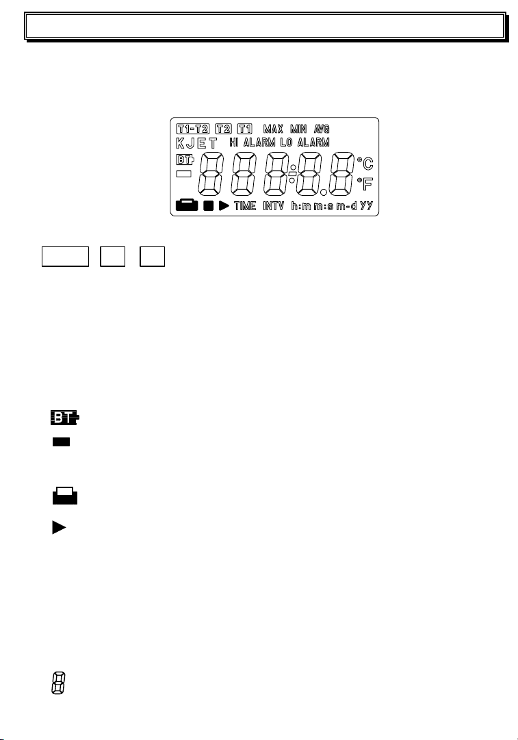
Display: 4-1/2 digit LCD
LCD illustration (see below)
Fig-1
T1-T2 , T2 , T1 Reflects the selected temperature display
configuration
MAX, MIN, AVG Maximum, Minimum or Average reading display
Avg = ½ (Previous reading + Current reading)
K , J , E , T Thermocouple types
HI ALARM Temperature exceeds high alarm limit (setpoint)
LO ALARM Temperature exceeds low alarm limit (setpoint)
Negative polarity; positive polarity assumed
Low battery symbol
℃, ℉
Celsius and Fahrenheit temperature units
Printer active
, ■
TIME Calendar time
INTV Interval printing symbol
h:m Hour : Minutes
m:s Minute: Seconds
m-d Month – Day
yy Calendar year
Seven segment display digit
Interval printing Start /Stop symbol
Page 5

Over Range or - appears.
Low battery indicator
Sampling Rate 1 reading per second (approx.)
Power Six 1.5V ‘AAA’ cells or 9V (500mA) adaptor
Battery Life (typ.)
30 hours (interval print set to 60 mins. & beeper off)
70 hours (no printing or beeper)
Input protection 60Vdc/24Vrms
Operating Temperature and Humidity
℉
32
to 122℉ (0℃ to 50℃) below 90% RH
Storage Temperature and Humidity
14℉ to 140℉ (-10℃ to 60℃) below 70% RH
Dimensions 7.6 (L) x 2.9 (W) x 1.5 (H)” (193 × 74 × 37 mm)
Weight Approx. 12.8 oz. (365g) with batteries & paper.
Accessories Carrying case, batteries, thermo-paper (2), Alarm
DIN cable and temperature probe (type K)
Page 6

Printer
Thermo-printing type with 16 characters per line using 38mm
width plain thermo-paper.
Instant printing: Print on demand (button press)
Interval printing: Print at desired interval from 00:00:03 to 23:59:59
2-2 Electrical Specifications
Accuracy
Type K: ±( 0.1% rdg + 0.8℃ ) ( 0~1333℃ )
±( 0.1% rdg + 1.4℉ ) ( 32~2431℉ )
Type J : ±( 0.1% rdg + 0.8℃ ) ( 0~ 760℃ )
±( 0.1% rdg + 1.4℉ ) ( 32~1400℉ )
Type E: ±( 0.1% rdg + 0.8℃ ) ( 0~ 703℃ )
±( 0.1% rdg + 1.4℉ ) ( 32~1297℉ )
Type T: ±( 0.1% rdg + 0.8℃ ) ( 0~ 400℃ )
±( 0.1% rdg + 1.4℉ ) ( 32~ 752℉ )
Type K/J/E/T: ±( 0.5% rdg + 1.0℃ ) ( -200~ 0℃ )
Resolution:0.1℃/0.1℉
(23℃ ±5℃, below 80%RH)
±
( 0.5% rdg + 1.8℉ ) ( -328 ~ 32℉)
Temperature Coefficient:
0.1 times the applicable accuracy specification per ℃ from 0℃ to 18℃ and 28
℃
to 50℃ ( 32℉ to 64℉ and 82℉ to 122℉ )
Measurement Range:
(
℃
℃
℃
℃
(
(
(
Type K: -200 ~ 1333
Type J: -200 ~ 760
Type E: -200 ~ 703
Type T: -200 ~ 400
-328~2431
-328~1400
-328~1297
-328~ 752
)
℉
)
℉
)
℉
)
℉
Page 7
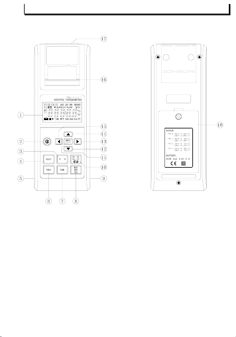
III. Description of Thermometer
Fig-2
1. LCD
Displays readings, units, symbols, and decimal points
2. POWER
Powers the unit on/off
3. UNIT
Selects the temperature units
(℃ / ℉)
Page 8

4. PRINT
Prints current measurement (print format shown below):
LINE 1
1 0 : 5 1 : 1 2 1 1 - 0 2
LINE 2
T 1 K - 0 0 2 3 . 0
C
Line 1: (Time) Hour: minute: second, month- day
Line 2: Measurement channel, thermocouple type, temp., and unit.
Stops interval printing at any time and prints current reading.
Press for 2 seconds to enable interval printing. Unit will remain in
the interval printing mode until this button is pressed again or the
FEED button is pressed.
5. 9V-ADAPTOR SOCKET (3.5φ)
6. FEED PAPER (Fig-3) :
Advances the thermo-paper one line.
Cancels printing.
7. TIME:
Calendar program button.
8. MAX / MIN / AVG:
Press to scroll through maximum, minimum and
average readings for channels T1 / T
/ T1-T2.
2
Fig-3
Page 9

9. High / Low Alarm output connector
Fig-4
Pin 1: GND ( external supply low voltage )
Pin 2: VCC ( external supply high voltage )
Pin 3: SYNC ( external trigger signal )
Pin4 (High Alarm) and pin5 (Low Alarm) signals must be
synchronized with pin3. Pin5 and pin4 will not function
(always low) unless SYNC (pin3) is high. If SYNC is low, then
pin4 and pin5 will be low.
Pin41: High Alarm
If the reading is higher than the high alarm setpoint, then (pin 4)
will be high, otherwise, it will be low.
Pin 51: Low Alarm
If the reading is less than or equal to the low alarm limit, (pin 5)
will go high.
1
The Pin 4 and 5 outputs may be delayed 0.4 seconds due to the
datalogger’s A/D scanning time.
Description of the DIN cable:
Red wire VCC (external supply high voltage)
Black wire GND (external supply low voltage)
Yellow SYNC (external trigger signal)
White High Alarm
Purple Low Alarm
Page 10

Note: voltage VCC to GND is 16V Maximum, 5V Minimum.
GND≦SYNC≦VCC
Example :
,
High Alarm= 1300.5
℃
Low Alarm= -50.5℃
If LCD reading ≧ 1300.5℃
Result : High Alarm output reading approx 5V
Low Alarm output reading approx 0V
If LCD reading ≦ -50.5℃
Result : Low Alarm output reading approx 5V
High Alarm output reading approx 0V
Example :
,
Hi alarm= 25.5
If LCD reading = 25.5
℃
Lo alarm= 25.5℃
℃
Page 11

Result : Hi Alarm output reading approx 5V
Lo Alarm output reading approx 5V
10. T
1/T2 /T1-T2
Press to select the display method, T
measurements :
1, T2, T1-T2
.
11. MENU:
Press to enter and step through the set-up mode. (Hold down the key to
scroll quickly).
12. UP:Press to increase the value of a parameter.
13. RIGHT:Press to move to a desired parameter.
14. DOWN:Press to decrease a parameter’s value.
:
15. LEFT
Parameters
Press to move to a desired parameter.
(in sequence):
K/J/E/T (thermocouple types)
00/01 Interval printing enable (01) and disable (00)
℃/℉
(Temperature units)
High/Low Alarm (high and low alarm limits)
Ex: K Type (1333.3 ~ -200.0℃)
J Type ( 760.5 ~ -200.0℃)
INTV (printing interval range: 00h:00m:03s to 23h:59m:59s
Interval printing start / stop time (range: 00h:00m to 23h:59m)
Calendar year (range up to 2999)
Calendar month-day (ranges from 01-01 to 12-31)
Calendar hour-minute (ranges from 00h:00m to 23h:59m)
Calendar minute-second (ranges from 00m:00s to 59m:59s)
16. Out of Thermo-paper.
17. Temperature probe sockets.
18. Battery compartment and cover:Six 1.5V ‘AAA’ batteries
Page 12

IV. PRECAUTIONS AND PREPARATIONS FOR MEASUREMENT
1. Before use, examine the device to ensure that no shipping damage
has occurred.
2. Save all packing materials.
3. Ensure that the batteries are correctly placed in the case or that the
9V adaptor is correctly connected.
4. An unsecured battery cover can cause measurement error.
5. To avoid battery leakage, remove batteries if this meter will not be
used for a long period of time.
6. Do not use or store this meter outside the operating or storage
environmental specifications.
Page 13

V. OPERATIONAL GUIDE
A. This meter can be operated with batteries or 9V Adaptor, If using
batteries, remove the rear cover and install the batteries (observe
polarity). If using the 9V Adaptor, ensure that is connected firmly and
correctly. Select the desired temperature probe for your application
and insert it into the tempture probe socket.
B. Press the button to power the meter. If “ ” appears, check that
the probe is connected properly and that it is operational.
C. To enter the programming mode, press the “
MENU
” button, to exit,
press it again. Use the left and right arrow buttons ( or ) to
select a parameter for editing; Use the up and down buttons ( or
) to increase or decrease the value of a parameter. When
modifing a parameter, the parameter’s symbol will blink.
The available parameters in sequence:
1. INTERVAL PRINTING STATUS (01/ENABLE, 00/DISABLE):
See LCD display example below in Fig-5
2. TYPE OF THERMOCOUPL (K/J/E/T) :
Fig-5
Fig-6
Page 14

3. ALARM UNIT (
℃/℉
):
Fig-7
4. FIRST THREE DIGITS IN HI ALARM (-399~399):
Example :
Hi Alarm = 1234.5
℃
Fig-8
5. LAST TWO DIGITS IN HI ALARM (00~99):
Fig-9
6. FIRST THREE DIGITS IN LO ALARM (-399~399):
Example :
Lo Alarm = -50.8
℃
Fig-10
7. LAST TWO DIGITS IN LO ALARM (00~99):
Fig-11
Page 15

8. HOUR OF INTERVAL PRINTING (00~23):
MINUTE OF INTERVAL PRINTING (00~59):
9.
Fig-12
Fig-13
10. SECOND OF INTERVAL PRINTING (00~59):
Fig-14
11. HOUR OF START INTERVAL PRINTING TIME (00~23):
Fig-15
12. MNUTE OF START INTERVAL PRINTING TIME(00~59):
Fig-16
※
NOTE : Print time START must be before print time STOP.
Page 16

13. HOUR OF STOP INTERVAL PRINTING TIME (00~23) :
MINUTE OF STOP INTERVAL PRINTING TIME (00~59):
14.
Fig-17
Fig-18
15. FIRST TWO DIGITS OF CALENDAR YEAR (19~29):
Fig-19
16. LAST TWO DIGITS OF CALENDAR YEAR (00~99):
Fig-20
17. MONTH DIGITS OF CALENDAR MONTH-DAY (01~12):
Fig-21
Page 17

18. DAY DIGITS OF CALENDAR MONTH-DAY (01~31):
HOUR DIGITS OF CALENDAR HOUR-MINUTE (00~23):
19.
Fig-22
Fig-23
20. MINUTE DIGITS OF CALENDAR HOUR-MINUTE (00~59):
Fig-24
21. SECOND DIGITS OF CALENDAR MINUTE-SECOND (00~59) :
Fig-25
Page 18

If interval printing is enabled in the programming mode, the printer will
print as in the examples below:
11:54:00 11-02
INTV:00:00:10
First two lines:
Line 1: hour:minute:second month-day (start printing time)
Line 2: interval printing time hour:minute:second
Following two lines:
Line 1: hour:minute:second month-day (interval printing time)
Line 2: measurement channel, thermocouple type, reading, and unit.
Last two lines:
Line 1: hour:minute:second month-day (stop pointing time)
Line 2: interval printing time hour:minute:second
※
NOTE : If the print button is pressed during this period the last two
lines will not be printed.
Page 19

If the print button is held for 2 seconds, the printer will print as follows:
12:58:18 11-02
INTV:00:00:10
12:58:28 11-02
–
:58:
:58:
:58:
:59:
:59:
:59:
0039.5 ℃
38 11-02
48 11-02
58 11-02
–
0035.2 ℃
08 11-02
18 11-02
20 11-02
T1 K
12
T1 K – 0L. ℃
12
T1 K – 0L. ℃
12
T1 K
12
T1 K – 0L. ℃
12
T1 K –0037.0 ℃
12
T1 K – 0L. ℃
First two lines:
Line 1: hour:minute:second month-day
Line 2: interval printing time hour:minute:second
Following lines:
Line 1: hour:minute:second month-day (interval printing time)
Line 2: function test channel, type and reading with polarity,
decimal point and unit.
To stop printing, press the Print or the Feed button.
Page 20

VI. INTERVAL PRINTING SETUP
1. SETUP INTERVAL PRINT (with 24 hour maximum interval limit).
Enter the Menu mode by pressing the MENU button.
Enable interval printing as described on page 11 (fig-5) using the /
buttons (01 is enable).
Use the / buttons to scroll through the available editing parameters
as described on page 13 (fig-12).
Setup Interval/Start/Stop print time by pressing / buttons as
described on pages 13, 14, (fig-12 to fig-18). Note that the START print
time must be before the STOP time.
Press the MENU button to return to normal operating mode. The INTV
symbol will be shown on LCD indicating that interval printing is active.
2. SETUP INTERVAL PRINT (without 24 hour limit)
Enter the Menu mode by pressing the MENU button.
Disable Interval Printing as described on page 11 (fig-5) using the /
buttons (00 is disable).
Set Interval Print Time using the / button as shown on page 13,
(fig-12 to fig-14).
Press MENU again to return to normal operation.
Press and hold the PRINT button for about 3 seconds, the INTV symbol
will be shown on LCD indicating that interval printing is active.
3. During the Interval Print period, no buttons can be used except the PRINT
and FEED button. When the PRINT button is pressed, one more line will
be printed before the interval printing session is aborted. Pressing the
FEED button aborts interval printing immediately.
Page 21

VII. BATTERY REPLACEMENT
1. When battery power falls low, the will appear on the LCD.
Replace the six 1.5V ‘AAA’ batteries
2. After the temperature probe(s) have been disconnected and the
meter power turned off, remove the rear battery cover.
3. Remove batteries from the holder and replace with six 1.5V
‘AAA’ alkaline batteries.
4. Secure the battery cover.
VIII. Calibration and Repair Services
Extech offers complete repair and calibration services
for all of the
products we sell. For periodic calibration, NIST certification on most
products or repair of any Extech product, call customer service for
details on services available. Extech recommends that calibration be
performed on an annual basis to ensure calibration integrity.
Support Hotline (781) 890-7440
Tech support: Ext. 200; Email: support@extech.com
Repair/Returns: Ext. 210; Email: repair@extech.com
Website: www.extech.com
Version 1.0 August 2002
Copyright © 2002 Extech Instruments Corporation.
All rights reserved including the right of reproduction in whole or in part in any form.
 Loading...