

Page 1
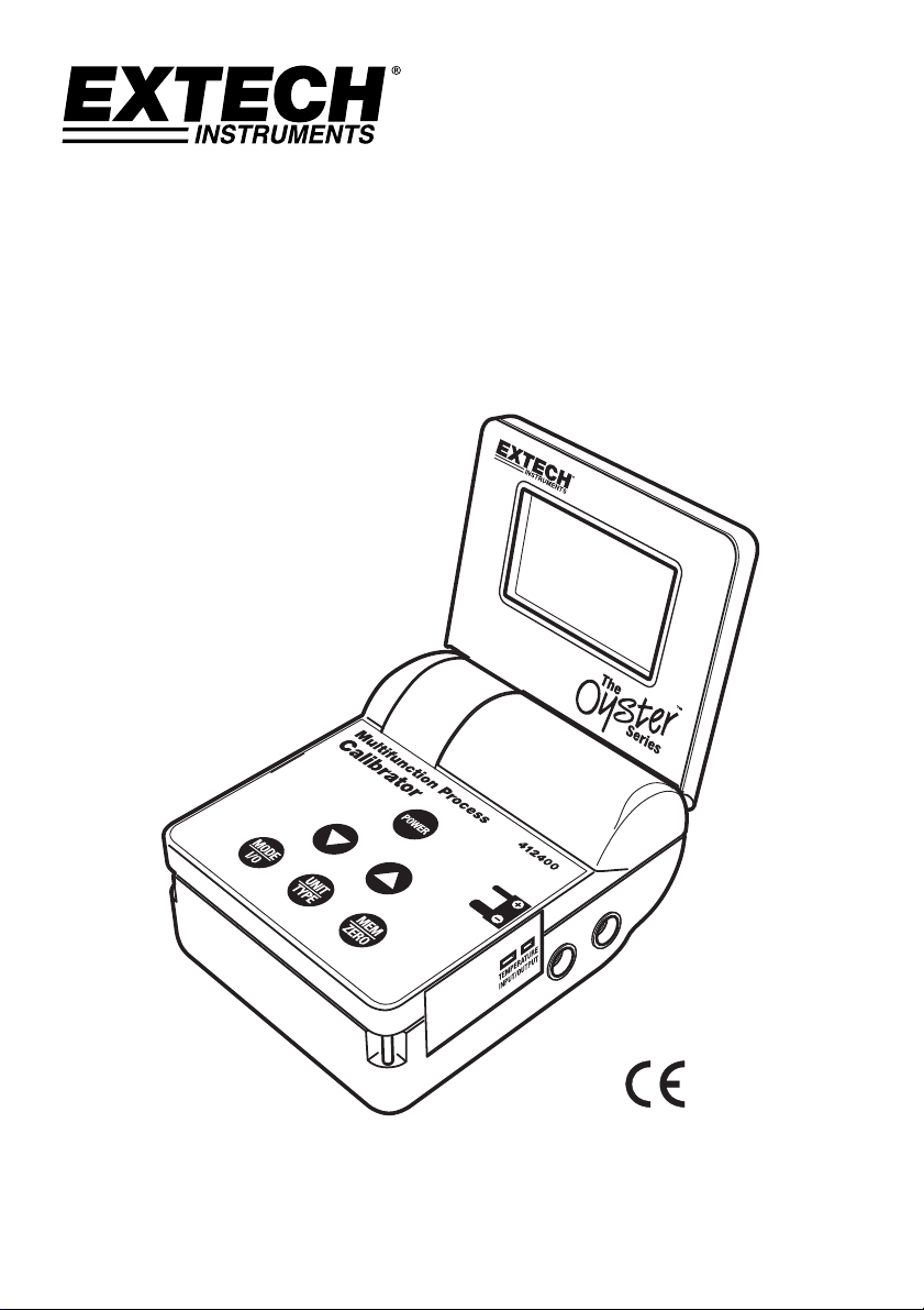
Model 412400
Multifunction Process Calibrator
User's Guide
Page 2
Introduction
Congratulations on your purchase of the Extech Model 412400 Process Calibrator. The Model
412400 can Measure or Source Current, Voltage, and Thermocouple Temperature signals. In
SOURCE/MEASURE mode, the meter can also Power and Measure simultaneously with 24Vdc
loop power.
The calibrator’s five (5) memory locations for each calibration function (which are also user
programmable) can be used to provide stepped outputs automatically. In automatic mode, the
output steps can be programmed to run continuously or in single-shot mode.
The Oyster Series meters employ a convenient flip up display with neck-strap (lanyard) for handsfree operation and run on battery power or from an AC adaptor.
This instrument is shipped fully tested and calibrated and, with proper use, will provide years of
reliable service.
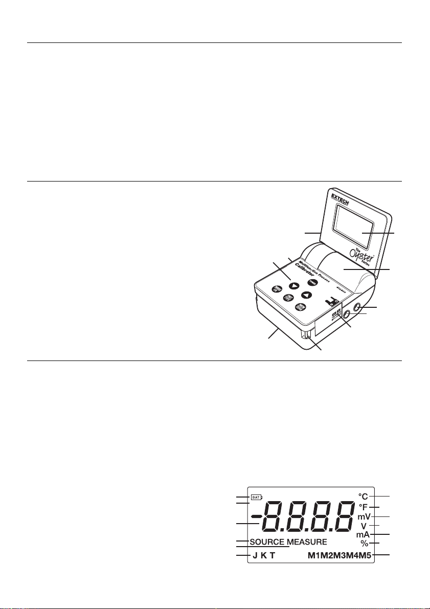
Meter Description
1. LCD display
2. Lanyard storage compartment
3. Positive test lead banana jack (red)
4. Negative test lead banana jack (black)
5. Thermocouple Input / Output jack
6. Lanyard posts (one on each side)
7. Battery compartment (bottom)
8. Keypad
9. AC adaptor jack
10. Flip up display
Display Description
10
9
8
5
7
6
1
2
3
4
1. Low battery icon
2. Auto Power Off icon
3. Numerical representation of measured, sourced, or stored signal value (also used to display
mnemonics for programming)
4. SOURCE or MEASURE mode status icon
5. Loop power indicator
6. Thermocouple types
7. Temperature unit of measure (Celsius)
8. Temperature unit of measure (Fahrenheit)
9. Millivolt unit of measure
10. Voltage unit of measure
11. Milliamp unit of measure
12. Per cent
13. Five memory locations
1
APO
2
3
4
5
6
2
24V Loop Power
412400-EU-EN v5.3 07/13
8
10
12
7
9
11
13
Page 3

Operation
POWER BUTTON AND AUTO POWER OFF FEATURE
1. Use the POWER button to turn the unit ON or OFF. When the unit is switched on, a short selftest will display after which the LCD will stabilize.
2. This meter is powered by six (6) ‘AA’ 1.5V batteries or by an AC adaptor.
3. When the battery symbol appears on the upper left-hand corner of the LCD display, or if the
instrument does not switch on with a press of the POWER button, replace the batteries. Low
battery power may cause inaccurate readings and erratic meter operation.
4. This instrument is equipped with Auto Power OFF which turns the meter off after 10 minutes of
inactivity. To toggle this feature off and on, press and hold the POWER button (starting with the
meter ON) until the APO icon is on or off.:
MEASURE MODE
1. Press the POWER button. The meter will turn on in the MEASURE mode and in the function
last used.
2. Press and release the MODE I/O button to change to the function desired (Temperature,
Voltage, Current or Current with 24V Loop Power.
3. Press the UNIT TYPE button to select the current units (mA, %) or temperature units (°C, °F).
Voltage is autoranging.
4. In the temperature function, press and hold the UNIT TYPE button to change the thermocouple
type (J, K, T).
5. Connect the signal to be measured to the input jacks for current and voltage or the miniconnector for temperature.
6. Read the measured value in the display
INPUT ZERO
An input zero is performed when the meter is first turned on. The zero can also be performed
manually at any time (with or without an input signal connected
1. In the MEASURE mode, press and release the MEM/ZERO button.
2. The units icon will flash and after a few seconds the meter will return to normal operation.
MEASUREMENT OVER-RANGE and UNDER-RANGE INDICATION
In the Voltage and Current functions, measured signals above or below the specified ranges will
be indicated by “HHHH” for above range and “LLLL” for below range.
In the Temperature function, OPEN will be displayed if the measured signal is outside of the
specified range or a thermocouple is not inserted into the temperature jack.
3
412400-EU-EN v5.3 07/13
Page 4

SOURCE MODE
1. Press the POWER button. The meter will turn on in the MEASURE mode and in the function
last used.
2. Press and release the MODE I/O button to change the function desired (Temperature, Voltage,
or Current)
3. Press and hold the MODE I/O button until SOURCE appears in the display.
4. Press the UNIT TYPE button to select the current units (mA, %) or temperature units (°C, °F).
Voltage is autoranging.
5. Adjust the output using the ▲▼buttons
Press the
Press and hold the
Press and hold the
digit steps
▲ button once to increase the value in one-digit steps.
▲ button to increase the value in ten-digit steps.
▲ button > 2 sec and then press the ▼ to increase the value in 100
To decrease the value, use the
6. In the Current function, the -25% to 125% output range corresponds to the 0 to 24mA output
range.
%
Display
mA
output
NOTE: The “SOURCE” icon will blink until the output level has stabilized. The most
common cause for the “SOURCE” icon to continue blinking is that the load impedance is
too high in the current mode or too low in the voltage mode.
-25% 0% 25% 50% 75% 100% 125%
0mA 4mA 8mA 12mA 16mA 20mA 24mA
▼ button as described above.
4
412400-EU-EN v5.3 07/13
Page 5

MEMORY (MEM) BUTTON
The calibrator has five (5) memory locations for each function for stepped calibration. Default output
values are noted below. The memory locations/output values can be selected manually, or the
series of five values can be stepped automatically for the voltage and current functions. For the
temperature function, only manual stepping is available.
The default values initially stored in the memory locations can be modified by the user. Once
changed, the modified valued will be held until manually changed again.
MANUAL Sourcing from stored memory values
1. Select the Source mode
2. Press the MEM button. The M1 icon (memory location 1) will appear in the display and the
value stored in that location will be displayed and sourced.
3. Subsequent presses of the MEM button will step through the five memory locations.
AUTOMATIC Sourcing from stored memory values (Voltage/Current modes only)
1. Select the Source mode
2. Press and hold the UNIT-TYPE button until ‘StPC’ (continuous stepping) or ‘StPS’ (single
shot stepping) appears on the LCD.
3. In Single Shot mode (StPS), the meter will automatically step through all of the memory
locations (M1 through M5 and then M5 through M1) and then automatically stop. Each step
is held for 10 seconds.
4. In Continuous mode (StPC), the meter runs through the same sequence as in Single Shot
mode except the sequence repeats indefinitely until the user aborts the test by pressing the
UNIT-TYPE key.
5. When the sequence ends, either continuous or single shot, the meter will briefly display
‘END’ and then return to the standby mode.
Storing values into memory
1. Select and display a memory location (M1 to M5)
2. Use the
3. Press and HOLD the MEM button for > 2 seconds.
4. The Memory location number will flash for several seconds while the value is being stored.
5. The displayed value will now be stored in the displayed memory location.
▲ ▼buttons to adjust the display to the desired source value. Speed scrolling is
explained earlier.
When the flashing stops, the value is stored.
5
412400-EU-EN v5.3 07/13
Page 6

Default Memory Values
Five common source values are pre-programmed for each mode and stored in the Calibrator’s
memory; the user can replace these values as needed; refer to the Table below:
Default Memory Values
M1 M2 M3 M4 M5
mV, V 0mV 2.50V 5.00V 7.50V 10.00V
mA 4mA 8mA 12mA 16mA 20mA
% 0% 25% 50% 75% 100%
Temperature M1 M2 M3 M4 M5
Type J / K (oF) 32o 212o 932o 1382o 1832o
Type J / K (oC) 0o 100o 500o 750o 1000o
Type T (oF) 32o 212o 392o 572o 752o
Type T (oC) 0o 100o 200o 300o 400o
Note: If ERR displays in place of a stored memory value, the value is outside the specified
range of the instrument. Select another value that is within the specified range.
Battery Replacement
When the battery symbol appears on the upper left-hand corner of the LCD, or if the unit does not
switch on when the POWER button is pressed, replace the six (6) ‘AA’ 1.5V batteries.
1. The battery compartment is located on the bottom of the instrument
2. Remove the screw that secures the battery compartment cover
3. Slide the battery compartment cover off of the instrument
4. Replace the batteries observing polarity
5. Replace the compartment cover and the screw
You, as the end user, are legally bound (Battery ordinance) to return all used batteries
and accumulators; disposal in the household garbage is prohibited!
You can hand over your used batteries / accumulators at collection points in your
community or wherever batteries / accumulators are sold!
Disposal: Follow the valid legal stipulations in respect of the disposal of the device at the
end of its lifecycle
6
412400-EU-EN v5.3 07/13
Page 7

Specifications
General Specifications
Display 9999 count LCD
Meter Power Six (6) 1.5V ‘AA’ batteries or AC adaptor
Auto Power OFF Meter automatically powers off after 10 minutes of inactivity (can be
Current output capability 24mA @ 1000 ohms
Loop Power 24Vdc (1000 ohm max. load)
Accessories Supplied Batteries, AC adaptor, Calibration cable, and User Guide
Battery Life Approximately 7 hours @ 24mA output with 1000 ohm load
Power Supply 9V DC @ 1A, 5.4 mm, center positive/barrel negative
Operating Temperature 5ºC to 40ºC (41ºF to 104ºF)
Storage Temperature -20ºC to 60ºC (-4ºF to 140ºF)
Operating Humidity Max 80% up to 31ºC (87ºF) decreasing linearly to 50% at 40ºC
Storage Humidity <80%
Operating Altitude 2000meters (7000ft.) maximum.
Dimensions 96 x 118 x 45mm (3.8 x 4.7 x 1.8”) folded
Weight 340g (12 oz.)
Specifications Voltage/Current
Mode Function Range Resolution Accuracy
Measure Voltage 0 to 20.00V 1mV to 1999mV
Current 0.00 to 50.00mA 0.01mA
% -25% to +230% 0.1%
Mode Function Range Resolution Accuracy
Source Voltage 0 to 10.00V 1mV to 1999mV
Current 0.00 to 24.00mA 0.01mA
% -25.0 to 125.0% 0.1%
Specifications Temperature
Mode Function Range Resolution Accuracy
Source
Type J -58 to 1830oF
&
Measure
Type K -58 to 2498oF
Type T -184 to 752oF
Allrightsreservedincludingtherightofreproductioninwholeorinpartinanyform
disabled)
(104ºF)
10mV thereafter
±(0.075% of rdg + 1d)
Whichever is greater
10mV thereafter
±(0.075% of rdg + 1d)
Whichever is greater
o
-50 to 1000
-50 to 1370
-120 to 400
C
o
o
1000
o
C
o
C
0.1
1.0o ≥ 1000o
±(0.15% rdg + 1.8
Copyright©2013FLIRSystems,Inc.
ISO‐9001Certified
www.extech.com
7
or
± 3 digits
or
± 3 digits
o
F/ 1oC)
412400-EU-EN v5.3 07/13
 Loading...