

Page 1
User's Guide
Integrating Sound Level Datalogger
Model 407780
Page 2
Introduction
Congratulations on your purchase of the Extech 407780 Integrating Sound Level Meter.
The 407780 with programmable integrating time provides precise linearity over a wide
range (100dB) and displays Leq, SEL, SPL, MAX-L, and MIN-L measurements.
Response time (FAST, SLOW, and IMPULSE) and frequency weighting (A and C) are
programmable. The analog output (AC and DC) can be used with headphones, chart
recorders or other devices to store data. The 407780 with PC Interface and real-time
calendar clock datalogs (stores) up to 32,000 readings for later transfer to PC. Careful
use of this meter will provide years of reliable service.
Meter Description
1
2
3
7
8
4
5
9
10
11
6
12
2
Model 407780 Version 2.1 09/07
Page 3

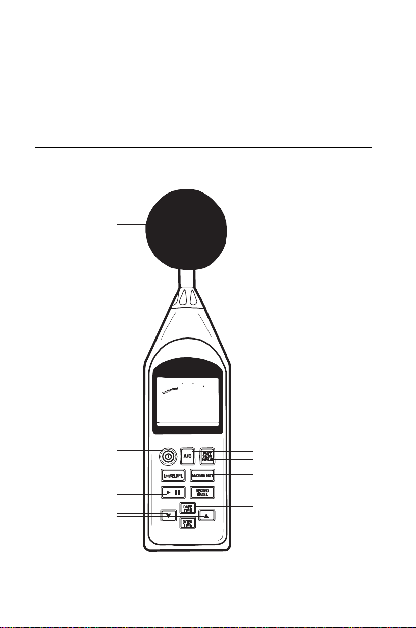
Refer to the diagram on the facing page:
1. 1/2-inch microphone (shown with windscreen)
2. LCD display
3. Power Switch
4. Leq / SEL / SPL select switch
5. RUN / Pause switch
6. Use the UP/DOWN arrow keys to change the measurement preset time.
7. A / C Frequency weighting select switch
8. FAST / SLOW / IMPULSE time weighting select switch.
FAST: 125ms
SLOW: 1 second
IMPULSE: 35ms with slow decay
9. Press to select MAX MIN recording. Press again to step through MAX and MIN values.
Press and hold for 3 seconds to erase the MAX and MIN values and exit this mode.
10. RECORD / ERASE
Record standby: The RECORD symbol appears in standby mode.
Recording: The RECORD symbol flashes once per second while recording.
Erase data: Press & hold the RECORD/ERASE key for 3 seconds to erase data (the
entire LCD will flash three times).
11. Real time clock with calendar
12. Measuring time selection for Leq and SEL
13. RS-232 interface connector (Located on bottom, not shown)
14. AC output terminal (located on side, not shown)
2 Vrms at 130dB
Output impedance 600Ω Max.
Output signal uses standard 3.5mm phono jack (supplied). Signal on tip; ground on
sleeve.
15. DC output terminal (located on side, not shown)
Output: 10mV/dB
Output impedance 100Ω max.
Output signal uses standard 3.5mm phono jack (supplied). Signal on tip and ground on
sleeve.
16. CAL (calibration) potentiometer (located on side, not shown)
17. External DC 6V power supply terminal (located on side, not shown)
18. Tripod mounting screw (located on rear, not shown)
19. Battery cover (located on rear, not shown)
3
Model 407780 Version 2.1 09/07
Page 4
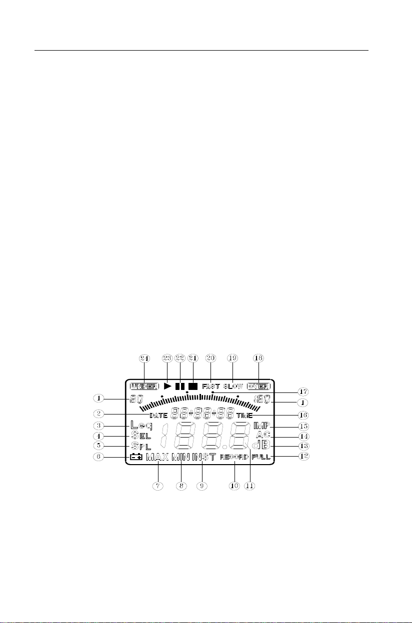
Display Description
1. Level range
2. Date information
3. Leq: Equivalent continuous
4. SEL: Sound exposure level
5. SPL: Instantaneous sound
pressure level
6. Low-Battery indicator
7. MAX: Maximum SPL value is
held during measurement.
8. MIN: Minimum SPL value is
held during measurement.
9. INST: Instantaneous of sound
pressure level
10. Data recording
11. Measuring value
12. Memory full
13. Unit
14. Frequency weighting (A/C)
15. IMPULSE time weighting
16. When the TIME display icon
switches on, the real time clock
is displayed. When the TIME
icon is off the display shows
elapsed time for Leq and SEL
measurements.
17. Bargraph (100dB range with 50
segments)
18. Range over
19. SLOW time weighting
20. FAST time weighting
21. Measurement completion of Leq
and SEL
22. Measurement interruption of
Leq and SEL
23. Leq and SEL readings
24. Under Range
4
Model 407780 Version 2.1 09/07
Page 5

Operation
This meter can be used in two different manners. As an Integrating Sound Level Meter
or as a Sound Pressure Meter (SPL).
Integrating Sound Level Meter
LEQ Mode
In the LEQ mode the display indicates the integrated (average) level for the run period. If no
run time has been accumulated the display shows dashes.
Taking Measurements
1. Turn the meter on by pressing the green on/off button.
2. Select the LEQ mode by pressing the Leq SEL SPL button until LEQ appears on the
LCD.
3. Select the desired Frequency Weighting as needed (A or C).
Change the Frequency Weighting by pressing the 'A/C' button. The 'A' or 'C' icon will
display on the right-hand area of the LCD.
4. Select the desired Response Time as needed (Fast or Slow)
Change the Response Time by pressing the 'FAST/SLOW/IMPULSE' button. The
'FAST' 'SLOW' icon will display on the upper area of the LCD.
5. Select the desired Run Time. There are 13 preset time settings available (To perform a
manual recording select the 24 hour interval.)
Change the run time by pressing the INTEG TIME button. The run time will appear in the
middle of the LCD. Press the ▲or▼ button to select the preset time setting.
6. Hold the instrument comfortably in hand and away from your body or position it on a
tripod. Point the microphone toward the noise source
7. Press ►
and begin counting. While running the meter will display ► at the top
of the display.
The meter will stop automatically after the preset time interval has
expired and will display ■ and the LEQ for the recording interval.
To take another LEQ simply press ►
It is also possible to record each session. Simply press RECORD before pressing ►
The RECORD icon will appear on the bottom right of the display and flash while the
session is in progress. For instructions on retrieving the recorded data please refer to
the software manual on the CD included with your meter.
1 second 3 seconds 10 seconds 30 seconds 1 minute
5 minutes 8 minutes 10 minutes 30 minutes 15 minutes
30 minutes 1 hour 8 hours 24 hours
button to begin measuring. The run time counter will zero
Leq
Leq
again.
68.7
►
00:00:00
68.7
■
00:00:30
dB
dB
.
5
Model 407780 Version 2.1 09/07
Page 6

SEL Mode
In the SEL mode (Sound Exposure Level) – the display indicates the constant sound level in
decibels which, if lasting for one second, would deliver the same amount of acoustical energy
as that delivered over the entire measurement period. If no run time has been accumulated
the display shows dashes.
1. Turn the meter on by pressing the green on/off button.
2. Select the SEL mode by pressing the Leq SEL SPL button until SEL appears on the
LCD.
3. Select the desired Frequency Weighting as needed (A or C).
Change the Frequency Weighting by pressing the 'A/C' button. The 'A' or 'C' icon will
display on the right-hand area of the LCD.
4. Select the desired Response Time as needed (Fast or Slow)
Change the Response Time by pressing the 'FAST/SLOW/IMPULSE' button. The
'FAST' 'SLOW' or IMP icon will display.
5. Select the desired Run Time. There are 13 preset time settings available (To perform a
manual recording select the 24 hour interval)
6. Hold the instrument comfortably in hand and away from your body or position it on a
7. Press ►
1 second 3 seconds 10 seconds 30 seconds 1 minute
5 minutes 8 minutes 10 minutes 30 minutes 15 minutes
30 minutes 1 hour 8 hours 24 hours
Change the run time by pressing the INTEG TIME button. The run time will appear in the
middle of the LCD. Press the ▲or▼ button to select the preset time setting.
tripod. Point the microphone toward the noise source
button to begin measuring. The run time counter will zero
and begin counting. While running the meter will display ► at the top
of the display.
SEL
The meter will stop automatically after the preset time interval has
expired and will display ■ and the SEL for the recording interval.
SEL
It is also possible to datalog the session. Simply press RECORD
before pressing ►
. The RECORD icon will appear on the bottom
right of the display and flash while the session is in progress. For instructions on
retrieving the recorded data please refer to the software manual on the CD included with
your meter.
6
Model 407780 Version 2.1 09/07
Page 7

Sound Pressure Measurements (SPL)
In SPL mode the display shows readings of the sound pressure level.
1. Turn the meter on by pressing the green on/off button.
2. Select the SPL mode by pressing the Leq SEL SPL button until SPL appears on the
LCD.
3. Select the desired Frequency Weighting as needed (A or C).
Change the Frequency Weighting by pressing the A/C button. The 'A' or 'C' icon will
display on the right-hand area of the LCD.
Note: With ‘A’ weighting selected, the meter responds like the human ear. ‘A’
weighting is commonly used for environmental measurements, OSHA regulatory
testing, law enforcement, and workplace design. Select ‘C’ weighting for flat
response measurements. ‘C’ weighting is typically used for the sound level analysis
of machines, engines, etc. Most hearing conservation related testing is performed
using 'A' Weighting.
4. Select the desired Response Time as needed (Fast, Slow or Impulse).
Change the Response Time by pressing the 'FAST/SLOW/IMPULSE' button. The 'FAST'
'SLOW' or IMP icon will display.
Note: Select FAST to capture noise peaks and noises that occur very quickly. In
FAST mode, the meter responds in 125ms. Select the SLOW Mode (meter responds
in 1s) to monitor a sound source that has a reasonably consistent noise level or to
average quickly changing levels. In IMPULSE mode the meter responds in 35ms
and is used to capture sounds such as those produced at a shooting range.
Selection of Fast or Slow is determined by the application and any directives or
standards related to that application. Most hearing conservation related testing is
performed using a SLOW Response Time setting.
5. Hold the instrument comfortably in hand and away from your body or position it on a
tripod. Point the microphone toward the noise source, the sound pressure level will be
displayed on the meter’s LCD display.
MIN/MAX Function
Press the MAX MIN INST button to begin capturing the, Maximum (MAX) OR Minimum
(MIN) sound values. The display will indicate the MAX or MIN value (depending on which is
selected) captured since the MAX/MIN button was pressed. Press and hold the
MAX MIN INST button to return to the instantaneous reading mode
Note:
When the meter is measuring the following buttons cannot be used:
• FAST, SLOW, IMPULSE
• A/C Weighting
• DATE/TIME
7
• INTEG TIME
• RECORD ERASE
• UP/DOWN Arrow keys
Model 407780 Version 2.1 09/07
Page 8

Setting the Real Time Calendar Clock
1. Start with the meter off. Press and hold the DATE TIME button, and while holding the
key, press the green ON/OFF button to switch the instrument on. Release the power
button when the meter flashes three times.
2. A blinking number indicates the currently selected parameter. The first blinking
parameter will represent the current year. Use the UP and DOWN arrow keys to set the
correct year.
3. Press the DATE TIME button to move to the next parameter (month). Use the arrow
keys to set the correct month.
4. Repeat step 3 to set the day, hour, minute, and second.
5. To confirm the new date and time press the DATE TIME button. Note that the 407780
has a back-up battery.
Note: The clock can also be set via the accompanying software program. See the
software manual on the enclosed CD for the steps on this procedure.
Powering the meter
1. Install the four (4) ‘AA’ 1.5V batteries in the rear battery compartment. Observe
polarity.
2. If the battery level falls low the battery symbol will appear on the LCD. Replace the
batteries when the symbol appears.
3. For use of the optional AC Adaptor, plug the adaptor into the side of the meter in the
jack labeled ‘6V’ and then into an appropriate AC power source.
8
Model 407780 Version 2.1 09/07
Page 9

Calibration
Calibrating the Model 407780 Integrating Sound Level Datalogger
requires an acoustical calibrator such as the Extech Model 407766 or
407744.
1. Configure the meter as follows:
• Display: SPL (dBA)
• Time weighting mode: FAST
• Measurement mode: INST
2. Insert the 407780 microphone into the opening of the acoustical
calibrator.
3. Adjust the 407780 calibration potentiometer until the 407780
display matches the acoustical calibrator output signal (typically 94
or 114dB).
Maintenance & Cleaning
Service not covered in this manual should be performed by qualified personnel
•
Periodically wipe the case with a dry cloth. Do not use abrasives or solvents.
•
Analog output
The 407780 has two analog output jacks located on its right side; one for AC and one for DC.
For DC, the meter transmits 10mv / dB. For AC the full scale value is 0.707V. The output
impedance is 600Ω for AC and 100Ω for DC.
The supplied 3.5mm stereo mini-plug can be used to assemble a cable to connect to either of
the meter’s analog output jacks. When using a stereo plug, like the one supplied, short the
Tip and the Ring (see diagram below). Ground (negative) connects to the Sleeve while the
positive signal is taken from the Tip/Ring. For mono plugs, ground connects to the Sleeve
while the positive signal is taken from the Tip. The meter output can then be transmitted to a
headset, chart recorder, datalogger, or other data storage device.
Stereo
Sleeve
Ring
Tip
Mono
Sleeve
Tip
9
Model 407780 Version 2.1 09/07
Page 10

Datalogging
For detailed information on using the software please refer the software manual on the
enclosed CD.
The 407780 can store up to 32,000 measurements. To view, save, print, and manipulate
the data, the records must be downloaded to a PC. Each recorded data set holds the
following information:
• Date and Time of reading
• Response time and frequency
weighting
• Sampling time (rate of data
recording)
• Total number of records
• Leq
• Max L
• Min L
• SEL
• Measurement duration
10
Model 407780 Version 2.1 09/07
Page 11

Start Recording
1. Connect the sound level meter to a PC via the supplied RS-232 cable.
TM
2. Use the supplied Windows
software to activate communication.
3. Set the sampling rate and the measurement time in the supplied software. The meter
can now record remotely (disconnected from the PC) at the rate selected.
4. Press the RECORD/ERASE key to put the meter in Record Standby. The RECORD
display icon will appear on the display.
5. Press the RUN/PAUSE key to start data recording. The RECORD icon will flash once
per second. One reading will be stored for each sampling interval (set in the sampling
rate parameter above).
6. When the measurement time expires, the meter stops recording and the RECORD
display icon switches off.
7. The recorded data can then be down-loaded to the PC using the supplied Windows
software.
Erasing Records
1. When the meter’s memory is full, the FULL display icon will appear on the display.
2. Press and hold the RECORD ERASE key for 3 seconds to erase all records. The FULL
display icon will switch off when the data is cleared.
TM
11
Model 407780 Version 2.1 09/07
Page 12

Specifications
General Specifications
Applicable Standards IEC 651 / 804 type 2 and ANSI S1.4 type 2
Measurement types SPL, SEL, Leq, MAX-L, and MIN-L
Measurement range 30 to 130dB
Frequency Range 31.5Hz to 8kHz
Frequency weighting ‘A’ and ‘C’
Response time FAST, SLOW, and IMPULSE selections
Linearity range 100dB
Display resolution 0.1dB
Accuracy ±1.5db (94dB @ 1kHz)
Microphone 0.5” Electret Condensor
Numeric Display 4-digit LCD
Display update rate Twice per second
Bargraph Display 4dB per step (over 100dB range) with 50 segments
Bargraph update rate 16 times per second
Display warnings ‘OVER’ and ‘UNDER’ range status indicators
Analog outputs DC: 10mV per dB; AC: 2Vrms full scale
Power supply Four (4) 1.5V ‘AA’ batteries (optional AC adaptor)
Battery life 20 hours (approx.)
Operating conditions 41 to 104
Storage conditions 14 to 140
Dimensions 10.4 x 2.8 x 0.8" (265 x 72 x 21mm)
Weight Approx. 10.9 oz. (310g)
Supplied Material
Adjustment screwdriver
Batteries (four ‘AA’ 1.5V cells)
Operation Manual
CD with Windows
TM
Software and software manual
RS-232 Interface cable
Windscreen
3.5mm plug for analog output access
o
F (5 to 40oC); 90% Relative Humidity
o
F (-10 to 60oC); 75% Relative Humidity
12
Model 407780 Version 2.1 09/07
Page 13

Warranty
EXTECH INSTRUMENTS CORPORATION warrants this instrument to be free of defects
in parts and workmanship for one year from date of shipment (a six month limited warranty
applies to sensors and cables). If it should become necessary to return the instrument for
service during or beyond the warranty period, contact the Customer Service Department at
(781) 890-7440 ext. 210 for authorization or visit our website www.extech.com for contact
information. A Return Authorization (RA) number must be issued before any product is
returned to Extech. The sender is responsible for shipping charges, freight, insurance and
proper packaging to prevent damage in transit. This warranty does not apply to defects
resulting from action of the user such as misuse, improper wiring, operation outside of
specification, improper maintenance or repair, or unauthorized modification. Extech
specifically disclaims any implied warranties or merchantability or fitness for a specific
purpose and will not be liable for any direct, indirect, incidental or consequential damages.
Extech's total liability is limited to repair or replacement of the product. The warranty set
forth above is inclusive and no other warranty, whether written or oral, is expressed or
implied.
Calibration and Repair Services
Extech offers repair and calibration services for the products we sell. Extech also
provides NIST certification for most products. Call the Customer Service Department for
information on calibration services available for this product. Extech recommends that
annual calibrations be performed to verify meter performance and accuracy.
Technical support: Extension 200; E-mail: support@extech.com
Repair & Returns: Extension 210; E-mail: repair@extech.com
Product specifications subject to change without notice
For the latest version of this User’s Guide, Software updates, and other
up-to-the-minute product information, visit our website: www.extech.com
Extech Instruments Corporation, 285 Bear Hill Rd., Waltham, MA 02451
All rights reserved including the right of reproduction in whole or in part in any form.
Support line (781) 890-7440
Copyright © 2005 Extech Instruments Corporation
13
Model 407780 Version 2.1 09/07
 Loading...