

Page 1
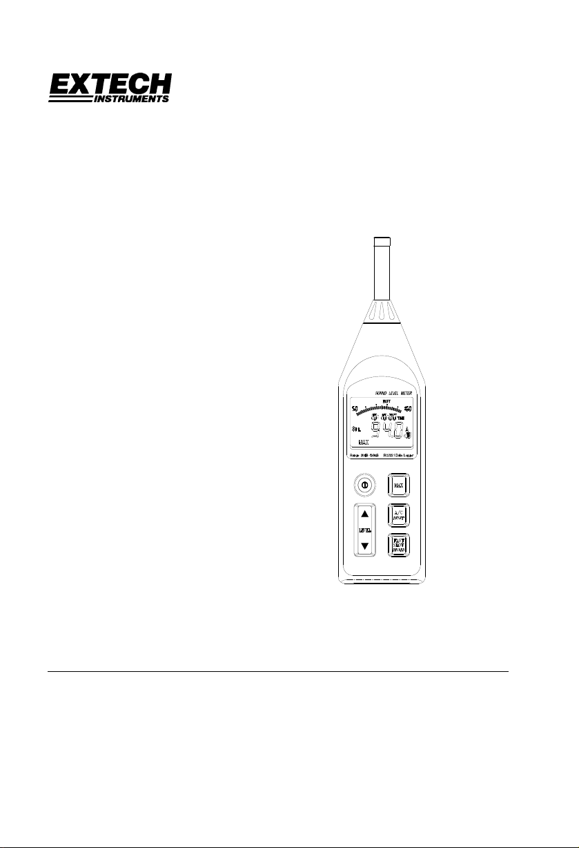
User's Manual
Datalogging Sound Level Meter
Model 407764
Range: 30dB to 130dB
•
4-digit LCD Display with 0.1dB resolution
•
A and C Frequency Weighting
•
RS-232 PC Interface with
•
128,000 point datalogger an d
Date / Time Stamp
Auto-Ranging
•
Introduction
Congratulations on your purchase of Extech’s Datalogging Sound Level Meter. The meter is
capable of performing all your noise measurements needs in addition to it’s capabilities for data
acquisition (direct data storage to a PC) or datalogging (data storage to internal memory for
later download). Data storage enables the user to save data, analyze data and generate
reports. This professional meter, with proper care, will provide years of safe reliable service.
Page 2

Specifications
Applicable Standards IEC651 Type 2, ANSI S1.4 Type 2
Accuracy ±1.5dB (under reference conditions)
Frequency range 31.5Hz - 8KHz
Measuring level 30 - 130dB
Frequency weighting A and C
Microphone 0.5” Electret condenser microphone
Display 4-digit LCD
Resolution: 0.1dB
Display period: 0.5 sec.
Bargraph 50dB scale (1dB steps). Display period: 50mS; Auto-ranging:
100dB scale, 2dB steps
Sampling rate 50mS
Memory size 128,000 records / 255 sets (non-volatile memory)
Datalogging sample rate 1 to 86,400 seconds per record
Time weighting FAST: 125mS, SLOW: 1 sec.
MAX Maximum reading held
Level ranges 30-80dB, 40-90dB, 50-100dB, 60-110 dB, 70-120dB, 80-130dB
(Total of 6 ranges)
Auto range 30 to 130dB
Linearity range 50dB
Alarm function OVER indicator for readings higher than high limit.
UNDER indicator for readings lower than low limit.
AC output 0.707 Vrms at Full Scale
Output impedance approx. 600Ω
DC output 10mV / dB
Output impedance approx. 100Ω
Power supply Four 1.5V ‘AA’ batteries
Battery life Approx. 30 hrs continuous operation
AC adap ter Voltage: 6VDC
Voltage Ripple: < 100mVpp
Supply Current: > 100mADC
Socket: Pin Ground
Casing: Positive
External Diameter: 3.5mm
Operating temperature 32 to 104
Operating humidity 10 to 80%RH
Storage temperature 14 to 140
o
F (0 to 40oC)
o
F (-10 to 60oC)
Storage humidity 10 to 80%RH
Memory size 128,000 data records with Date and Time Stamping
RS-232 Interface Baud rate: 9600bps
Dimensions 10.4 x 2.8 x 1.4” (265 × 72 × 35mm
Weight Approx. 11.5 oz. (358g) including battery
Accessories Batteries, carrying case, screwdriver, windscreen, 3.5mm plug, RS-232
cable , Windows
TM
compatible software.
Safety symbols
Meter is protected throughout by double insulation or reinforced
insulation.
CE Complies with EMC
2
Model 407764 Version 2.1 9/07
Page 3
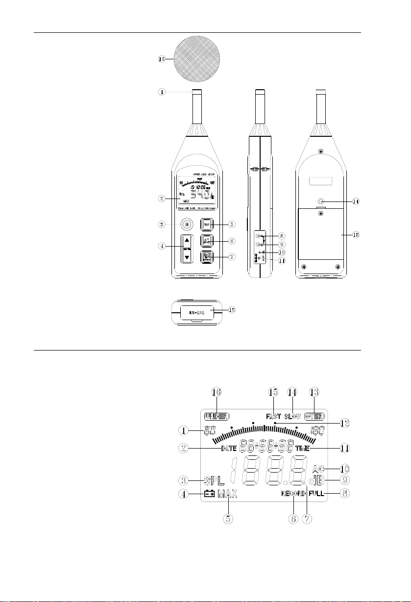
Meter Description
1. Microphone
2. Display
3. Power switch
4. Level range control switch
5. MAX hold switch
6. Frequency weighting switch
7. Response time select switch
8. AC output terminal
9. DC output terminal
10. CAL (calibration) pot.
11. External DC 6V power
12. RS-232 interface connector
13. Battery cover
14. Tripod mounting screw
15. Wind-screen
(Figure 1)
Display Description
1. Range selection
2. Date information
3. SPL: Instantaneous sound pressure level
4. Low-Battery
5. MAX: Maximum SPL value is held
6. Data recording
7. Measurement value
8. Memory full
9. Units
10. Frequency weighting (A/C)
11. TIME function
12. 50dB level (Bargraph)
13. Over range
14. SLOW time response
15. FAST time response
16. Under range
(Figure 2)
3
Model 407764 Version 2.1 9/07
Page 4

Measurement Preparation
Read the following safety information before attempting to operate the meter
•
Use the meter only as specified or the meter's built-in protection may be impaired.
•
Maintenance & Cleaning
Service not covered in this manual should be performed by qualified personnel
•
Periodically wipe the case with a dry cloth. Do not use abrasives or solvents.
•
Battery Replacement
When the battery voltage drops to a critical level, the
symbol appears on the LCD. Replace
batteries as soon as possible after the battery symbol appears. The batteries (4 AA) are located
in the rear battery compartment. Remove the single Philips head screw (center rear) for access
to the batteries.
Measurements
Default Configuration
1. The meter's default configuration is as follows: 40 to 90dB, 'A' Frequency Weighting, and
'FAST' Response Time
2. The LCD will reflect the meter's configuration.
Measurement Considerations
1. Use a windscreen to cover the microphone in windy conditions.
2. Calibrate the meter often, especially if the meter has not been used for a long time.
3. Do not store/operate the meter in high temperature/humidity for long periods of time.
4. Keep the meter and the microphone dry.
5. Avoid severe vibration when using the meter.
6. Remove the battery when the meter will be stored for long periods of time.
Frequency Weighting
Change the Frequency Weighting by pressing the 'A/C' button. The 'A' or 'C' icon will display on
the right-hand area of the LCD.
Note: With ‘A’ weighting selected, the meter responds like the human ear (boosting and cutting
the noise amplitude over the frequency spectrum - see Appendix). ‘A’ weighting is used for
environmental measurements, OSHA regulatory testing, law enforcement, and workplace
design. Select ‘C’ weighting for flat response measurements (no boost or cut). ‘C’ weighting is
suitable for the sound level analysis of machines, engines, etc. Most OSHA related testing is
performed using 'A' Weighting and SLOW Response Time settings.
Response Time
Change the Response Time by pressing the 'FAST/SLOW' button. The 'FAST' or 'SLOW' icon
will display on the upper area of the LCD.
Note: Select FAST to capture noise peaks and noises that occur very quickly. In FAST mode,
the meter responds in 200ms. Select the SLOW Mode (meter responds in 500ms) to monitor a
sound source that has a reasonably consistent noise level or to average quickly changing
levels. Selection of Fast or Slow is determined by the application and any directives or
standards related to that application.
Auto/Manual Range
Press the LEVEL button up arrow to scroll through the following ranges: 30-80dB, 40-90,
50-100dB, 60-110, 70-120, 80-130 and 30-130dB (auto). The displa y will reflect the range for
each button press.
Use Auto Range when the noise source is relatively steady. Use one of the Manual
Notes:
ranges may be required if the dB levels are changing over a wide range.
4
Model 407764 Version 2.1 9/07
Page 5

Operation
1. Power the meter and select the desired Response Time (Fast or Slow) and Frequency
Weighting (A or C).
2. Select the desired range.
3. Hold the instrument comfortably in hand or position on tripod. Point the microphone
toward the noise source, the sound pressure level will be displayed on the meter’s LCD
display.
4. When MAX (maximum hold) mode is selected by pressing the MAX key, the instrument
captures and holds the maximum noise level reading on the display. Press the MAX key
again to clear the MAX reading.
Calibration
Note that a Sound Level Calibrator is required. Set up the meter as listed in Step 1 below.
To calibrate the meter;
1. Display: SPL (dBA)
Response Time: FAST
Disable the MAX function
Range: 70 to 120dB.
2. Insert the microphone carefully into the sound
level calibrator.
3. Power the calibrator and adjust the Sound Level Meter’s
CAL potentiometer (as shown in figure at right) to match
the Calibrator’s output.
4. Typically, a Sound Level Calibrator will supply 94dB
or 114dB at 1KHz. Adjust the Sound Level Meter’s CAL
potentiometer for a 94dB or 114dB LCD display
(Figure-3)
Analog output
The 407764 has two analog output jacks located on its right side; one for AC and one for DC.
For DC, the meter transmits 10mv / dB. For AC the full scale value is 0.707V. The output
impedance is 600Ω for AC and 100Ω for DC.
The supplied 3.5mm stereo mini-plug can be used to assemble a cable to connect to either of
the meter’s analog output jacks. When using a stereo plug, like the one supplied, short the Tip
and the Ring (see diagram below). Ground (negative) connects to the Sleeve while the positive
signal is taken from the Tip/Ring. For mono plugs, ground connects to the Sleeve while the
positive signal is taken from the Tip. The meter output can then be transmitted to a chart
recorder, datalogger, or other data storage device.
(Figure 4)
Stereo
Sleeve
Ring
Tip
5
Model 407764 Version 2.1 9/07
Mono
Sleeve
Tip
Page 6

DataLogging
The internal memory of the meter can store up to 128,000 reading in up to 255 recording
sessions (called sets). Prior to beginning data storage, the meter’s real time clock and the
datalogger’s sample rate must be set using the supplied software. The clock is set in the
Control Panel window and the sample rate is set in the Logger window.
1. Set the real time clock (if required).
2. Set the sample rate (if required).
3. To record data, press & hold the RECORD key for 3 seconds until the “RECORD” symbol
flashes once per second on the LCD. Press the Record key again to stop recording data.
4. If the recording memory is full, the “FULL” symbol will appear on the LCD.
5. To clear the recording memory press and hold the RESET key and power the meter. The
LCD will show the “dEL” icon letting the user know that the datalog memory has been
cleared.
6. To Download or Record data via a PC refer to the PC Interface section below.
PC Interface
Connecting the Meter to a PC
Refer to Figure 5. Connect the 9-pin male connector to the Sound Level Meter, and connect the
9-pin female connector to the 9-pin COM1 PC port.
PC Requirements (figure 5)
• 486 IBM compatible PC or better
• One 3.5" high density disk drive
• Available serial port.
• 4M Bytes H.D. storage space
• EGA or VGA monitor
• Windows 95, 98, 2000, NT, XP Operating System
• 3-button or 2-button Microsoft compatible
mouse. At least a 486 PC is recommended
for displaying all software windows with a
fast sampling rate (such as 1 second). If a 386/25 PC is used, you can only open one
window (LIST, GRAPH, ANALOG) at a time when using fast sampling rates.
Installing the Windows Application Program
Follow the instructions on the disk for installation. When installing the software, please use the
Visual Basic version (VB) on installation CD.
6
Model 407764 Version 2.1 9/07
Page 7

Software Control Panel Description
METER SIMULATION
The left side of the Control Panel window provides a replica of the meter’s front panel and
display.
MAX: Hold and update maximum value
A/C A/C weighting selection
RESET Reboot and clear the data memory
F/S Fast/Slow selection
REC Enable datalogging
LEVEL Set range
DATA ACQUISITION CONTROLS and DISPLAYS
MIN: Displays the minimum value recorded
MAX: Displays the maximum value recorded
TIME: Displays the Real Time Clock Setting
SAMPLING TIME Display of data acquisition sampling rate (Fig 7)
PC SAMPLING: Opens data acquisition sampling rate selection box. (Datalogging
<--RESET-->: Resets the MIN and MAX stored readings
SYSTEM TIME SET: Sets the meter’s clock to the value of the pc clock
SAVE AS: Opens the data file storage window (*.dat)
OPEN FILE: Opens the data file retrieve window (*.dat) (Fig.8)
FILE NAME: Displays name and location of data acquisition file
START RECORDING: After opening a file, click to start recording.
STOP RECORDING: Stop recording and close the file
EXIT Close program
(Figure-7) (Figure-8)
Selecting the datalog sample rate Opening a datalog file (*.dat)
The Control Panel (Figure 6)
sample rate is set in the MEMORY “Logger” window)
7
Model 407764 Version 2.1 9/07
Page 8

DISPLAY SELECTIONS
(Figure-9) (Figure-10)
GRAPH LIST
(Figure 11)
ANALOG
Logger Window (memory setup/ data download)
The Logger window sets the sample rate of the meter’s internal memory and provides the
controls to download display and save stored data.
MEMORY Displays memory size
REMAINING Displays amount of
TIME OF METER When clicked,
ID CODE Numeric Identification
SAMPLING Datalogger sample
NUMBER OF SETS Click on the bar to download the stored data
TIME OF RECORDING Click on the bar to display sets downloaded. Click on a set to select
NUMBERS OF REC Displays the number of records (data points) in the selected set.
SHOW DATA Display, Save or Graph data from selected set
unused memory
downloads and
displays the meter’s
date and time
code. Enter the code
in the box and click on
the bar to store the
code.
rate. Enter the sample
rate in the box (in
seconds) and click on
the SAMPLING bar to store the value.
data for display
8
Model 407764 Version 2.1 9/07
Page 9

DATA DOWNLOAD PROCEDURE
1. Click the MEMORY icon in the Control Panel screen.
2. Click the NUMBERS OF SETS button, the number of sets will appear.
3. Click on the TIME OF RECORDING button to view each recorded set.
4. Click on a SET in the TIME OF RECORDING box. The number of records in the set will
appear and the data will be downloaded from meter to PC. Save to disk if desired.
5. Click the SHOW DATA button for details on each record. Figure 13 shows the data list.
Select SAVE, PRINT, GRAPH, or EXIT from the menu choices.
Note: In the example for Figure 12, there are 3 sets of recorded data in memory. Set No. 3 has
15 records. Note: If you need to change the ID CODE or the SAMPLING time, click on the
desired parameter, type the changes and click on the bar.
(Figure-13) – List of datalogged set (Figure-14) – Graph of datalogged set
(Figure-15) – Selecting a range of datalogged records
9
Model 407764 Version 2.1 9/07
Page 10

Calibration / Repair Services
Extech offers complete repair and calibration services for all of the products we sell. For
periodic calibration, NIST certification or repair of any Extech product, call customer service for
details on services available. Extech recommends that calibration be performed on an annual
basis to insure calibration integrity.
Warranty
EXTECH INSTRUMENTS CORPORATION warrants this instrument to be free of d efects in parts
and workmanship for one year from date of shipment (a six month limited warranty applies on
sensors and cables). If it should become necessary to return the instrument for service during or
beyond the warranty period, contact the Customer Service Department at (781) 890-7440 ext. 210
for authorization or v isit our we bsite at ww w.extech.co m (clic k on C ont a ct Ex tec h and g o to Serv ic e
Department to request an RA number). A Return Authorization (RA) number must be issued before
any product is returned to Extech. The sender is responsible for shipping charges, freight, insurance
and proper packaging to pr event damag e in transit. This warr anty does not ap ply to defects resulting
from action of the user s uch as misus e, improp er wiring, o peratio n outs ide of spec ificatio n, improper
maintenance or repair, or unauthorized modification. Extech specifically disclaims any implied
warranties or merchantability or fitness for a specific purpose and will not be liable for any direct,
indirect, incidental or consequential damages. Extech's total liability is limited to repair or
replacement of the prod uct. The warr anty set forth ab ove is inclusive an d no other warra nty , whether
written or oral, is expressed or im pl ied.
Technical support: Extension 200; E-mail: support@extech.com
Repair & Returns: Extension 210; E-mail: repair@extech.com
Product specifications subject to change without notice
For the latest version of this User’s Guide, Software updates, and other
up-to-the-minute product information, visit our website:
Extech Instruments Corporation, 285 Bear Hill Rd., Waltham, MA 02451
Copyright © 2005 Extech Instruments Corporation. All rights reserved
including the right of reproduction in whole or in part in any form.
Support line (781) 890-7440
www.extech.com
10
Model 407764 Version 2.1 9/07
Page 11

Appendix - Typical ‘A’ Weighted Sound Levels
50 HP Siren (100')
Jet take-off (200')
Riveting machine
Subway (20')
Pneumatic drill (50')
Vacuum cleaner (10')
Large store
Small office
Residential area (night)
Whisper (5')
Threshold of hearing
130
110
90
70
50
30
10
140
120
Chain saw
100
Boiler room
80
Freight train (100')
Speech (1')
60
Large Office
Residence
40
Sound studio
20
0
11
Model 407764 Version 2.1 9/07
Page 12

Software Protocol
Data Protocol Baud rate: 9600bps
Byte1 Byte2 Byte3 Byte4 Byte5
02 Status Function 03
Leading byte Ending byte
Status Byte2
Bit7 Bit6 Bit5 Bit4 Bit3 Bit2 Bit1 Bit0
0 Fast C Normal Normal Normal 0 0 0 30-80
1 Slow A Max Full Rec 0 0 1 40-90
0 1 0 50-100
0 1 1 60-110
1 0 0 70-120
1 0 1 80-130
1 1 0 30-130
1 1 1
Function Byte3
Bit7 Bit6 Bit5 Bit4 (x10
0 Normal Normal Normal
2
) Bit3-0 (x10)
00-19
1 OVER UNDER BT
Function Byte4
Bit7-4 (x 10
0
0
) Bit3-0 (x10-1)
00-99
1
Command Protocol
Set time and date - Send 7 bytes
D YY MM dd hh mm ss
leading byte year month date hour min sec
Set sampling rate – Send 3 bytes
Set ID code – Send 3 bytes
Get software version – Output “V” - Receive 1 byte (0 – 255)
Get system argument – Output “Y” – Receive 10 bytes
ID Code
2bytes
Get time and date – Output “C” - Receive 6 bytes (YY+MM+dd+hh+mm+ss)
Receive 6 bytes (Sets+YY+MM+dd+hh+mm+ss+Status+Sample rate+Records)
Get Record – Output “K”+N records”
Receive (YY+MM+dd+hh+mm+ss+Status+Sampling rate+Records+1
record+…+nth record)
Erase Command: “EEE” (3 bytes) Set MAX spl; “M” (1 byte)
Switch Fast/Slow: “F” (1 byte) Stop Recording: “T” (1 byte)
Switch A/C: “A” (1 byte) Start Recording: “S” (1 byte)
Switch range: “U” (up), “P” (down) (1 byte)
W high byte low byte
leading byte 1 – 65535 sec
X high byte low byte
leading byte 1 – 65535
Version
1 byte
ID code
1 byte
Data sets
1 byte
Last address
3 bytes
Sample rate
2 bytes
st
record+2nd
12
Model 407764 Version 2.1 9/07
 Loading...